

Page 1

Part No. P0609327 02
March 17, 2004
Business Communications
Manager 3.6
IP Telephony Configuration
Guide
Page 2

2
Copyright © 2004 Nortel Networks
All rights reserved.
The information in this document is subject to change without noti ce. The statements, configurations, technical data, and
recommendations in this document are believed to be accurate and reliable, but are presented without express or implied
warranty. Users must take full responsibility for their applications of any products specified in this document. The
information in this document is proprietary to Nortel Networks NA Inc.
Trademarks
NORT EL NETWORKS is a trademark of Nortel Networks.
Microsoft, MS, MS-DOS, Windows, and W indows NT are re gistered trademarks of Microsoft Co rporation.
Symbol, Spe ctrum24, and NetVision are re gistered trademarks of Sym bol Technologies, Inc.
All other trademarks and registered trademarks are the prop erty of their respective owners.
P0609327 02
Page 3

Contents
Preface . . . . . . . . . . . . . . . . . . . . . . . . . . . . . . . . . . . . . . . . . . . . . . . . . . . . . . 15
Before you begin . . . . . . . . . . . . . . . . . . . . . . . . . . . . . . . . . . . . . . . . . . . . . . . . . . . . . 15
Symbols used in this guide . . . . . . . . . . . . . . . . . . . . . . . . . . . . . . . . . . . . . . . . . . . . . 15
Text conventions . . . . . . . . . . . . . . . . . . . . . . . . . . . . . . . . . . . . . . . . . . . . . . . . . . . . . 16
Acronyms . . . . . . . . . . . . . . . . . . . . . . . . . . . . . . . . . . . . . . . . . . . . . . . . . . . . . . . . . . . 17
Related publications . . . . . . . . . . . . . . . . . . . . . . . . . . . . . . . . . . . . . . . . . . . . . . . . . . 18
How to get help . . . . . . . . . . . . . . . . . . . . . . . . . . . . . . . . . . . . . . . . . . . . . . . . . . . . . . 19
Chapter 1
Introduction . . . . . . . . . . . . . . . . . . . . . . . . . . . . . . . . . . . . . . . . . . . . . . . . . . 21
IP telephones and VoIP trunks . . . . . . . . . . . . . . . . . . . . . . . . . . . . . . . . . . . . . . . . . . 22
IP telephones . . . . . . . . . . . . . . . . . . . . . . . . . . . . . . . . . . . . . . . . . . . . . . . . . . . . . 22
VoIP trunks. . . . . . . . . . . . . . . . . . . . . . . . . . . . . . . . . . . . . . . . . . . . . . . . . . . . . . . 22
Creating the IP telephony network . . . . . . . . . . . . . . . . . . . . . . . . . . . . . . . . . . . . . . . 23
Networking with Business Communications Manager . . . . . . . . . . . . . . . . . . . . . . 24
M1-IPT . . . . . . . . . . . . . . . . . . . . . . . . . . . . . . . . . . . . . . . . . . . . . . . . . . . . . . . . . . 25
Telephones . . . . . . . . . . . . . . . . . . . . . . . . . . . . . . . . . . . . . . . . . . . . . . . . . . . . . . 25
Gatekeepers on the network . . . . . . . . . . . . . . . . . . . . . . . . . . . . . . . . . . . . . . . . . 25
IP network . . . . . . . . . . . . . . . . . . . . . . . . . . . . . . . . . . . . . . . . . . . . . . . . . . . . . . . 26
Public Switched Telephone Network . . . . . . . . . . . . . . . . . . . . . . . . . . . . . . . . . . . 27
Key IP telephony concepts . . . . . . . . . . . . . . . . . . . . . . . . . . . . . . . . . . . . . . . . . . . . . 27
Codecs . . . . . . . . . . . . . . . . . . . . . . . . . . . . . . . . . . . . . . . . . . . . . . . . . . . . . . . . . . 27
Jitter Buffer. . . . . . . . . . . . . . . . . . . . . . . . . . . . . . . . . . . . . . . . . . . . . . . . . . . . . . . 28
QoS routing . . . . . . . . . . . . . . . . . . . . . . . . . . . . . . . . . . . . . . . . . . . . . . . . . . . . . . 29
3
Chapter 2
Prerequisites checklist . . . . . . . . . . . . . . . . . . . . . . . . . . . . . . . . . . . . . . . . . 31
Network diagram . . . . . . . . . . . . . . . . . . . . . . . . . . . . . . . . . . . . . . . . . . . . . . . . . . . . . 31
Network devices . . . . . . . . . . . . . . . . . . . . . . . . . . . . . . . . . . . . . . . . . . . . . . . . . . . . . 32
Network assessment . . . . . . . . . . . . . . . . . . . . . . . . . . . . . . . . . . . . . . . . . . . . . . . . . . 33
Resource assessment . . . . . . . . . . . . . . . . . . . . . . . . . . . . . . . . . . . . . . . . . . . . . . . . . 33
Keycodes . . . . . . . . . . . . . . . . . . . . . . . . . . . . . . . . . . . . . . . . . . . . . . . . . . . . . . . . . . . 34
System configuration for IP functions . . . . . . . . . . . . . . . . . . . . . . . . . . . . . . . . . . . . . 34
Finding the published IP address . . . . . . . . . . . . . . . . . . . . . . . . . . . . . . . . . . . . . . . . 35
Setting the Global IP (published IP) . . . . . . . . . . . . . . . . . . . . . . . . . . . . . . . . . . . . 35
Determining the published IP address . . . . . . . . . . . . . . . . . . . . . . . . . . . . . . . . . . 36
Media gateway parameters for IP service . . . . . . . . . . . . . . . . . . . . . . . . . . . . . . . . . . 37
VoIP trunks . . . . . . . . . . . . . . . . . . . . . . . . . . . . . . . . . . . . . . . . . . . . . . . . . . . . . . . . . 39
IP telephone records . . . . . . . . . . . . . . . . . . . . . . . . . . . . . . . . . . . . . . . . . . . . . . . . . . 40
IP Telephony Configuration Guide
Page 4

4 Contents
Chapter 3
Installing IP telephones. . . . . . . . . . . . . . . . . . . . . . . . . . . . . . . . . . . . . . . . . 41
IP telephony on the Business Communications Manager . . . . . . . . . . . . . . . . . . . . . . 42
Configuring Nortel Networks i-series telephones . . . . . . . . . . . . . . . . . . . . . . . . . . . . 42
Configuring DHCP . . . . . . . . . . . . . . . . . . . . . . . . . . . . . . . . . . . . . . . . . . . . . . . . . . . . 53
Checking IP server status . . . . . . . . . . . . . . . . . . . . . . . . . . . . . . . . . . . . . . . . . . . . . . 56
Modifying IP telephone status settings . . . . . . . . . . . . . . . . . . . . . . . . . . . . . . . . . . . . 57
Working with the features list . . . . . . . . . . . . . . . . . . . . . . . . . . . . . . . . . . . . . . . . . . . . 59
Resetting the Hot Desking password . . . . . . . . . . . . . . . . . . . . . . . . . . . . . . . . . . . . . . 61
Customizing feature labels . . . . . . . . . . . . . . . . . . . . . . . . . . . . . . . . . . . . . . . . . . . . . 63
Download firmware to a Nortel IP telephone . . . . . . . . . . . . . . . . . . . . . . . . . . . . . . . . 65
Deregistering DNs for IP telephones . . . . . . . . . . . . . . . . . . . . . . . . . . . . . . . . . . . . . . 66
Moving IP telephones . . . . . . . . . . . . . . . . . . . . . . . . . . . . . . . . . . . . . . . . . . . . . . . . . 69
Configuring a new time zone on a remote telephone . . . . . . . . . . . . . . . . . . . . . . . . . 70
Nortel Networks i2050 Software Phone . . . . . . . . . . . . . . . . . . . . . . . . . . . . . . . . . . . . 71
Preparing your system for IP telephone registration . . . . . . . . . . . . . . . . . . . . . . . 43
Setting IP terminal general settings . . . . . . . . . . . . . . . . . . . . . . . . . . . . . . . . . . . 43
Choosing a codec . . . . . . . . . . . . . . . . . . . . . . . . . . . . . . . . . . . . . . . . . . . . . . 45
Choosing a Jitter Buffer . . . . . . . . . . . . . . . . . . . . . . . . . . . . . . . . . . . . . . . . . 46
Installing i-series telephones . . . . . . . . . . . . . . . . . . . . . . . . . . . . . . . . . . . . . . . . . 46
Before installing . . . . . . . . . . . . . . . . . . . . . . . . . . . . . . . . . . . . . . . . . . . . . . . 46
Using a 3-port switch . . . . . . . . . . . . . . . . . . . . . . . . . . . . . . . . . . . . . . . . . . . 46
Connecting the i200X telephones . . . . . . . . . . . . . . . . . . . . . . . . . . . . . . . . . . . . . 47
Configuring the i20XX telephones to the system . . . . . . . . . . . . . . . . . . . . . . . . . 47
Registering the telephone to the system . . . . . . . . . . . . . . . . . . . . . . . . . . . . . . . . 48
Configuring telephone settings . . . . . . . . . . . . . . . . . . . . . . . . . . . . . . . . . . . . . . . 48
Troubleshooting IP telephones . . . . . . . . . . . . . . . . . . . . . . . . . . . . . . . . . . . . . . . 51
Operation issues . . . . . . . . . . . . . . . . . . . . . . . . . . . . . . . . . . . . . . . . . . . . . . . . . . 52
Setting up DHCP to work with IP terminals . . . . . . . . . . . . . . . . . . . . . . . . . . . . . . 53
IP telephony DHCP notes . . . . . . . . . . . . . . . . . . . . . . . . . . . . . . . . . . . . . . . . . . . 54
Using the Services button to access features . . . . . . . . . . . . . . . . . . . . . . . . . . . . 60
Notes about Hot Desking . . . . . . . . . . . . . . . . . . . . . . . . . . . . . . . . . . . . . . . . . . . 62
Changing features or labels on the memory buttons . . . . . . . . . . . . . . . . . . . . . . 64
Forcing a firmware download to an IP telephone. . . . . . . . . . . . . . . . . . . . . . . . . . 65
Deregistering a telephone using the IP record. . . . . . . . . . . . . . . . . . . . . . . . . . . . 66
Deregistering a telephone using a DN registration heading. . . . . . . . . . . . . . . . . . 67
Moving IP telephones and retaining the DN. . . . . . . . . . . . . . . . . . . . . . . . . . . . . . 69
Moving telephones and changing the DN . . . . . . . . . . . . . . . . . . . . . . . . . . . . . . . 69
Configuring the i2050 Software Phone for the local system . . . . . . . . . . . . . . . . . 71
Chapter 4
Installing NetVision telephones . . . . . . . . . . . . . . . . . . . . . . . . . . . . . . . . . . 73
NetVision connectivity . . . . . . . . . . . . . . . . . . . . . . . . . . . . . . . . . . . . . . . . . . . . . . . . . 73
P0609327 02
Page 5

Contents 5
Access points. . . . . . . . . . . . . . . . . . . . . . . . . . . . . . . . . . . . . . . . . . . . . . . . . . . . . 73
Keycodes . . . . . . . . . . . . . . . . . . . . . . . . . . . . . . . . . . . . . . . . . . . . . . . . . . . . . . . . 74
Handset and call functions . . . . . . . . . . . . . . . . . . . . . . . . . . . . . . . . . . . . . . . . . . . 74
Codecs . . . . . . . . . . . . . . . . . . . . . . . . . . . . . . . . . . . . . . . . . . . . . . . . . . . . . . . . . . 74
Configuring NetVision records . . . . . . . . . . . . . . . . . . . . . . . . . . . . . . . . . . . . . . . . . . . 75
Gathering system information before you start . . . . . . . . . . . . . . . . . . . . . . . . . . . 75
Assigning general settings . . . . . . . . . . . . . . . . . . . . . . . . . . . . . . . . . . . . . . . . . . 76
Monitoring H.323 service status . . . . . . . . . . . . . . . . . . . . . . . . . . . . . . . . . . . . . . 77
Assigning H.323 Terminals records . . . . . . . . . . . . . . . . . . . . . . . . . . . . . . . . . . . . 78
Pre-configuration notes for NetVision handsets . . . . . . . . . . . . . . . . . . . . . . . 78
Adding a NetVision record in the Unified Manager . . . . . . . . . . . . . . . . . . . . . 79
Modifying H.323 terminal records . . . . . . . . . . . . . . . . . . . . . . . . . . . . . . . . . . . . . . . . 81
Updating the H.323 terminals record . . . . . . . . . . . . . . . . . . . . . . . . . . . . . . . . . . . 81
Changing a handset Name . . . . . . . . . . . . . . . . . . . . . . . . . . . . . . . . . . . . . . . . . . 82
Changing the DN record of a handset . . . . . . . . . . . . . . . . . . . . . . . . . . . . . . . . . . 82
Deleting a NetVision telephone from the system . . . . . . . . . . . . . . . . . . . . . . . . . . 82
Deregistering a telephone . . . . . . . . . . . . . . . . . . . . . . . . . . . . . . . . . . . . . . . . . . . . . . 83
Chapter 5
Configuring local VoIP trunks. . . . . . . . . . . . . . . . . . . . . . . . . . . . . . . . . . . . 85
Pre-installation system requirements . . . . . . . . . . . . . . . . . . . . . . . . . . . . . . . . . . . . . 86
Keycodes . . . . . . . . . . . . . . . . . . . . . . . . . . . . . . . . . . . . . . . . . . . . . . . . . . . . . . . . 86
Published IP address . . . . . . . . . . . . . . . . . . . . . . . . . . . . . . . . . . . . . . . . . . . . . . . 86
SIP network data considerations . . . . . . . . . . . . . . . . . . . . . . . . . . . . . . . . . . . . . . 86
H.323 network applications considerations . . . . . . . . . . . . . . . . . . . . . . . . . . . . . . 86
Counting IP trunks . . . . . . . . . . . . . . . . . . . . . . . . . . . . . . . . . . . . . . . . . . . . . . . . . . . . 87
Determining the IP trunk count. . . . . . . . . . . . . . . . . . . . . . . . . . . . . . . . . . . . . . . . 87
Configuring media parameters . . . . . . . . . . . . . . . . . . . . . . . . . . . . . . . . . . . . . . . . . . 89
Setting up the local gateway . . . . . . . . . . . . . . . . . . . . . . . . . . . . . . . . . . . . . . . . . . . . 91
Modifying local gateway settings for H.323 and SIP trunks . . . . . . . . . . . . . . . . . 92
Notes about NPI-TON aliases for H.323 trunks . . . . . . . . . . . . . . . . . . . . . . . . . . . 96
Setting up SIP trunk subdomain names . . . . . . . . . . . . . . . . . . . . . . . . . . . . . . . . 97
Viewing SIP summary and status . . . . . . . . . . . . . . . . . . . . . . . . . . . . . . . . . . . . . . . . 98
Incoming calls: Assigning target lines . . . . . . . . . . . . . . . . . . . . . . . . . . . . . . . . . . . . . 98
How to use target lines. . . . . . . . . . . . . . . . . . . . . . . . . . . . . . . . . . . . . . . . . . . . . . 98
Configuring target lines . . . . . . . . . . . . . . . . . . . . . . . . . . . . . . . . . . . . . . . . . . . . . 99
Chapter 6
Setting up VoIP trunks for outgoing calls . . . . . . . . . . . . . . . . . . . . . . . . . 101
Setting up remote gateways and end points . . . . . . . . . . . . . . . . . . . . . . . . . . . . . . . 102
Configuring a remote gateway (H.323 trunks) . . . . . . . . . . . . . . . . . . . . . . . . . . . 103
Creating a remote gateway record . . . . . . . . . . . . . . . . . . . . . . . . . . . . . . . . 103
Configuring remote endpoints (SIP trunks) . . . . . . . . . . . . . . . . . . . . . . . . . . . . . 106
Setting up the SIP address book . . . . . . . . . . . . . . . . . . . . . . . . . . . . . . . . . 106
Outgoing call configuration . . . . . . . . . . . . . . . . . . . . . . . . . . . . . . . . . . . . . . . . . . . . 107
IP Telephony Configuration Guide
Page 6

6 Contents
Setting up VoIP trunks for fallback . . . . . . . . . . . . . . . . . . . . . . . . . . . . . . . . . . . . . . . 112
Quality of Service Monitor . . . . . . . . . . . . . . . . . . . . . . . . . . . . . . . . . . . . . . . . . . . . . 127
Managing H.323 and SIP trunks . . . . . . . . . . . . . . . . . . . . . . . . . . . . . . . . . . . . . 107
Configuring lines and creating line pools . . . . . . . . . . . . . . . . . . . . . . . . . . . . . . . 108
Configuring telephones to access the VoIP lines. . . . . . . . . . . . . . . . . . . . . . . . . 109
PSTN call to remote node . . . . . . . . . . . . . . . . . . . . . . . . . . . . . . . . . . . . . . . . . . 109
Call process . . . . . . . . . . . . . . . . . . . . . . . . . . . . . . . . . . . . . . . . . . . . . . . . . 110
Describing a fallback network . . . . . . . . . . . . . . . . . . . . . . . . . . . . . . . . . . . . . . . 113
Configuring routes for fallback . . . . . . . . . . . . . . . . . . . . . . . . . . . . . . . . . . . . . . . 114
Pre-configuration requirements . . . . . . . . . . . . . . . . . . . . . . . . . . . . . . . . . . 114
Adding routes for fallback . . . . . . . . . . . . . . . . . . . . . . . . . . . . . . . . . . . . . . . 114
Assigning the line pools to routes . . . . . . . . . . . . . . . . . . . . . . . . . . . . . . . . . 115
Adding the destination code for the fallback route . . . . . . . . . . . . . . . . . . . . 116
Configuring the schedules for the destination codes . . . . . . . . . . . . . . . . . . 117
Setting up the VoIP schedule to overflow . . . . . . . . . . . . . . . . . . . . . . . . . . . 118
Activating the VoIP schedule for fallback . . . . . . . . . . . . . . . . . . . . . . . . . . . 119
Deactivating the VoIP schedule . . . . . . . . . . . . . . . . . . . . . . . . . . . . . . . . . . 119
How fallback routing works . . . . . . . . . . . . . . . . . . . . . . . . . . . . . . . . . . . . . . . . . 120
Example: A private network configured for fallback . . . . . . . . . . . . . . . . . . . . . . 122
System programming for networking and fallback routes . . . . . . . . . . . . . . . 123
Making calls through a private VoIP network gateway . . . . . . . . . . . . . . . . . 125
Connecting an i200X telephone . . . . . . . . . . . . . . . . . . . . . . . . . . . . . . . . . . 125
PSTN fallback metrics . . . . . . . . . . . . . . . . . . . . . . . . . . . . . . . . . . . . . . . . . . . . . 126
Resetting the log . . . . . . . . . . . . . . . . . . . . . . . . . . . . . . . . . . . . . . . . . . . . . . 127
Quality of Service Status . . . . . . . . . . . . . . . . . . . . . . . . . . . . . . . . . . . . . . . . . . . 127
Updating the QoS monitor data . . . . . . . . . . . . . . . . . . . . . . . . . . . . . . . . . . . . . . 128
Viewing QoS monitoring logging . . . . . . . . . . . . . . . . . . . . . . . . . . . . . . . . . . . . . 128
Chapter 7
Optional VoIP trunk configurations . . . . . . . . . . . . . . . . . . . . . . . . . . . . . . 129
Port settings (firewall) . . . . . . . . . . . . . . . . . . . . . . . . . . . . . . . . . . . . . . . . . . . . . . . . 129
Using firewalls: adding PortRanges . . . . . . . . . . . . . . . . . . . . . . . . . . . . . . . . . . 129
Modifying PortRanges . . . . . . . . . . . . . . . . . . . . . . . . . . . . . . . . . . . . . . . . . . . . . 131
Port settings for legacy networks . . . . . . . . . . . . . . . . . . . . . . . . . . . . . . . . . . . . 132
Using a gatekeeper . . . . . . . . . . . . . . . . . . . . . . . . . . . . . . . . . . . . . . . . . . . . . . . . . . 133
Using Radvision ECS 3.2 GK as the gatekeeper . . . . . . . . . . . . . . . . . . . . . . . . . . . 134
Configuring Radvision for Business Communications Manager . . . . . . . . . . . . . 134
Using CSE 1000 as a gatekeeper . . . . . . . . . . . . . . . . . . . . . . . . . . . . . . . . . . . . . . . 136
Business Communications Manager requirements . . . . . . . . . . . . . . . . . . . . . . . 136
CSE 1000 configuration, adding an H.323 endpoint . . . . . . . . . . . . . . . . . . . . . . 137
Setting the H.323 Endpoint Dialing Plan . . . . . . . . . . . . . . . . . . . . . . . . . . . . . . . 137
Committing Gatekeeper Configuration Changes . . . . . . . . . . . . . . . . . . . . . . . . . 138
Configuring Codec Compatibility . . . . . . . . . . . . . . . . . . . . . . . . . . . . . . . . . . . . . 139
P0609327 02
Page 7

Contents 7
Setting Codecs on the CSE 1000 . . . . . . . . . . . . . . . . . . . . . . . . . . . . . . . . . . . . 139
Gatekeeper call scenarios . . . . . . . . . . . . . . . . . . . . . . . . . . . . . . . . . . . . . . . . . . 141
Faxing over VoIP lines . . . . . . . . . . . . . . . . . . . . . . . . . . . . . . . . . . . . . . . . . . . . . . . . 142
Operational notes and restrictions . . . . . . . . . . . . . . . . . . . . . . . . . . . . . . . . . . . . 142
IP trunking interoperability settings . . . . . . . . . . . . . . . . . . . . . . . . . . . . . . . . . . . . . . 143
Configuring NetMeeting clients . . . . . . . . . . . . . . . . . . . . . . . . . . . . . . . . . . . . . . . . . 145
Chapter 8
Typical network applications using MCDN . . . . . . . . . . . . . . . . . . . . . . . . 147
Setting up MCDN over VoIP with fallback . . . . . . . . . . . . . . . . . . . . . . . . . . . . . . . . . 147
MCDN functionality on fallback PRI lines. . . . . . . . . . . . . . . . . . . . . . . . . . . . . . . 148
Networking multiple Business Communications Managers . . . . . . . . . . . . . . . . . . . . 149
Multi-location chain with call center . . . . . . . . . . . . . . . . . . . . . . . . . . . . . . . . . . . . . . 151
Business Communications Manager to remote IP telephones . . . . . . . . . . . . . . . . . 152
Appendix A
Efficient Networking . . . . . . . . . . . . . . . . . . . . . . . . . . . . . . . . . . . . . . . . . . 153
Determining the bandwidth requirements . . . . . . . . . . . . . . . . . . . . . . . . . . . . . . . . . 153
Determining WAN link resources . . . . . . . . . . . . . . . . . . . . . . . . . . . . . . . . . . . . . 153
Link utilization. . . . . . . . . . . . . . . . . . . . . . . . . . . . . . . . . . . . . . . . . . . . . . . . . . . . 153
Network engineering . . . . . . . . . . . . . . . . . . . . . . . . . . . . . . . . . . . . . . . . . . . . . . . . . 154
Bandwidth requirements on half duplex links . . . . . . . . . . . . . . . . . . . . . . . . . . . 155
Bandwidth requirements on full duplex links . . . . . . . . . . . . . . . . . . . . . . . . . . . . 156
LAN engineering examples . . . . . . . . . . . . . . . . . . . . . . . . . . . . . . . . . . . . . . . . . 157
WAN engineering . . . . . . . . . . . . . . . . . . . . . . . . . . . . . . . . . . . . . . . . . . . . . . . . 158
QoS Monitoring Bandwidth Requirement. . . . . . . . . . . . . . . . . . . . . . . . . . . . . . . 159
Additional feature configuration . . . . . . . . . . . . . . . . . . . . . . . . . . . . . . . . . . . . . . . . . 159
Setting Non-linear processing . . . . . . . . . . . . . . . . . . . . . . . . . . . . . . . . . . . . . . . 159
Determining network loading caused by IP telephony traffic . . . . . . . . . . . . . . . 160
Enough link capacity . . . . . . . . . . . . . . . . . . . . . . . . . . . . . . . . . . . . . . . . . . . . . . 161
Not enough link capacity . . . . . . . . . . . . . . . . . . . . . . . . . . . . . . . . . . . . . . . . . . . 162
Other intranet resource considerations . . . . . . . . . . . . . . . . . . . . . . . . . . . . . . . . 162
Implementing the network, LAN engineering . . . . . . . . . . . . . . . . . . . . . . . . . . . . 162
Further network analysis . . . . . . . . . . . . . . . . . . . . . . . . . . . . . . . . . . . . . . . . . . . . . . 162
Components of delay . . . . . . . . . . . . . . . . . . . . . . . . . . . . . . . . . . . . . . . . . . . . . 163
Reduce link delay . . . . . . . . . . . . . . . . . . . . . . . . . . . . . . . . . . . . . . . . . . . . . . . . 163
Reducing hop count . . . . . . . . . . . . . . . . . . . . . . . . . . . . . . . . . . . . . . . . . . . . . . 164
Adjust the jitter buffer size . . . . . . . . . . . . . . . . . . . . . . . . . . . . . . . . . . . . . . . . . . 164
Reduce packet errors . . . . . . . . . . . . . . . . . . . . . . . . . . . . . . . . . . . . . . . . . . . . . 164
Routing issues . . . . . . . . . . . . . . . . . . . . . . . . . . . . . . . . . . . . . . . . . . . . . . . . . . . 165
Post-installation network measurements . . . . . . . . . . . . . . . . . . . . . . . . . . . . . . . . . . 165
IP Telephony Configuration Guide
Page 8

8 Contents
Appendix B
Silence compression. . . . . . . . . . . . . . . . . . . . . . . . . . . . . . . . . . . . . . . . . . 167
Silence compression on half-duplex links . . . . . . . . . . . . . . . . . . . . . . . . . . . . . . . . . 168
Silence compression on full-duplex links . . . . . . . . . . . . . . . . . . . . . . . . . . . . . . . . . . 170
Comfort noise . . . . . . . . . . . . . . . . . . . . . . . . . . . . . . . . . . . . . . . . . . . . . . . . . . . . . . 172
Appendix C
Network performance utilities. . . . . . . . . . . . . . . . . . . . . . . . . . . . . . . . . . . 173
Appendix D
Interoperability. . . . . . . . . . . . . . . . . . . . . . . . . . . . . . . . . . . . . . . . . . . . . . . 175
Speech path setup methods . . . . . . . . . . . . . . . . . . . . . . . . . . . . . . . . . . . . . . . . . . . 176
Media path redirection . . . . . . . . . . . . . . . . . . . . . . . . . . . . . . . . . . . . . . . . . . . . . . . . 177
Gatekeeper . . . . . . . . . . . . . . . . . . . . . . . . . . . . . . . . . . . . . . . . . . . . . . . . . . . . . . . . 177
Asymmetrical media channel negotiation, Net Meeting . . . . . . . . . . . . . . . . . . . . . . . 178
Setting up Remote Routers for IP Telephony Prioritization . . . . . . . . . . . . . . . . . . . . 179
Using VLAN on the network . . . . . . . . . . . . . . . . . . . . . . . . . . . . . . . . . . . . . . . . . . . 181
Symbol NetVision telephones . . . . . . . . . . . . . . . . . . . . . . . . . . . . . . . . . . . . . . . . . . 183
Software interoperability compatibility and constraints . . . . . . . . . . . . . . . . . . . . . . . 183
No feedback busy station. . . . . . . . . . . . . . . . . . . . . . . . . . . . . . . . . . . . . . . . . . . 178
Creating an outbound traffic filter . . . . . . . . . . . . . . . . . . . . . . . . . . . . . . . . . . . . 179
Sample criteria, ranges, and actions for UDP filtering . . . . . . . . . . . . . . . . . . . . . 180
Choosing DHCP for VLAN . . . . . . . . . . . . . . . . . . . . . . . . . . . . . . . . . . . . . . . . . 181
Specifying the site-specific options for VLAN . . . . . . . . . . . . . . . . . . . . . . . . . . . 182
H.323 trunk compatibility by software version . . . . . . . . . . . . . . . . . . . . . . . . . . . 183
H.323 trunk compatibility issues . . . . . . . . . . . . . . . . . . . . . . . . . . . . . . . . . . . . . 184
SIP trunk interoperability issues . . . . . . . . . . . . . . . . . . . . . . . . . . . . . . . . . . . . . 188
T.38 fax restrictions and requirements . . . . . . . . . . . . . . . . . . . . . . . . . . . . . . . . 189
Appendix E
Quality of Service. . . . . . . . . . . . . . . . . . . . . . . . . . . . . . . . . . . . . . . . . . . . . 191
Setting QoS . . . . . . . . . . . . . . . . . . . . . . . . . . . . . . . . . . . . . . . . . . . . . . . . . . . . . . . . 191
Measuring Intranet QoS . . . . . . . . . . . . . . . . . . . . . . . . . . . . . . . . . . . . . . . . . . . . . . 193
Measuring end-to-end network delay . . . . . . . . . . . . . . . . . . . . . . . . . . . . . . . . . 193
Measuring end-to-end packet loss . . . . . . . . . . . . . . . . . . . . . . . . . . . . . . . . . . . 194
Recording routes . . . . . . . . . . . . . . . . . . . . . . . . . . . . . . . . . . . . . . . . . . . . . . . . . 194
Adjusting Ping measurements . . . . . . . . . . . . . . . . . . . . . . . . . . . . . . . . . . . . . . 195
Adjustment for processing . . . . . . . . . . . . . . . . . . . . . . . . . . . . . . . . . . . . . . . . . . 195
Late packets. . . . . . . . . . . . . . . . . . . . . . . . . . . . . . . . . . . . . . . . . . . . . . . . . . . . . 195
Measurement procedure . . . . . . . . . . . . . . . . . . . . . . . . . . . . . . . . . . . . . . . . . . . 196
Other measurement considerations . . . . . . . . . . . . . . . . . . . . . . . . . . . . . . . . . . . 196
Decision: does the intranet meet IP telephony QoS needs? . . . . . . . . . . . . . . . . 197
Implementing QoS in IP networks . . . . . . . . . . . . . . . . . . . . . . . . . . . . . . . . . . . . . . . 198
Traffic mix . . . . . . . . . . . . . . . . . . . . . . . . . . . . . . . . . . . . . . . . . . . . . . . . . . . . . . 198
P0609327 02
Page 9

Contents 9
TCP traffic behavior . . . . . . . . . . . . . . . . . . . . . . . . . . . . . . . . . . . . . . . . . . . . . . . 199
Business Communications Manager router QoS support . . . . . . . . . . . . . . . . . . 199
Network Quality of Service . . . . . . . . . . . . . . . . . . . . . . . . . . . . . . . . . . . . . . . . . . . . 200
Network monitoring . . . . . . . . . . . . . . . . . . . . . . . . . . . . . . . . . . . . . . . . . . . . . . . 200
Quality of Service parameters . . . . . . . . . . . . . . . . . . . . . . . . . . . . . . . . . . . . . . . 201
Fallback to PSTN . . . . . . . . . . . . . . . . . . . . . . . . . . . . . . . . . . . . . . . . . . . . . . . . 201
Glossary . . . . . . . . . . . . . . . . . . . . . . . . . . . . . . . . . . . . . . . . . . . . . . . . . . . . 203
Index . . . . . . . . . . . . . . . . . . . . . . . . . . . . . . . . . . . . . . . . . . . . . . . . . . . . . . . 2 11
IP Telephony Configuration Guide
Page 10

10 Contents
P0609327 02
Page 11

Figures
Figure 1 Network diagram . . . . . . . . . . . . . . . . . . . . . . . . . . . . . . . . . . . . . . . . . . . . . . . . 24
Figure 2 Global IP settings . . . . . . . . . . . . . . . . . . . . . . . . . . . . . . . . . . . . . . . . . . . . . . . . 35
Figure 3 Selecting the Published IP address . . . . . . . . . . . . . . . . . . . . . . . . . . . . . . . . . . 36
Figure 4 System Configuration, Parameters screen . . . . . . . . . . . . . . . . . . . . . . . . . . . . . 37
Figure 5 Set registration properties . . . . . . . . . . . . . . . . . . . . . . . . . . . . . . . . . . . . . . . . . 43
Figure 6 IP terminal registration server status . . . . . . . . . . . . . . . . . . . . . . . . . . . . . . . . . 56
Figure 7 IP Terminal status . . . . . . . . . . . . . . . . . . . . . . . . . . . . . . . . . . . . . . . . . . . . . . . . 57
Figure 8 IP Terminal status dialog box . . . . . . . . . . . . . . . . . . . . . . . . . . . . . . . . . . . . . . . 58
Figure 9 IP Telephony Features List . . . . . . . . . . . . . . . . . . . . . . . . . . . . . . . . . . . . . . . . . 59
Figure 10 Add/Modify Telephony Features List . . . . . . . . . . . . . . . . . . . . . . . . . . . . . . . . . 60
Figure 11 IP Terminal Status tab list . . . . . . . . . . . . . . . . . . . . . . . . . . . . . . . . . . . . . . . . . . 61
Figure 12 Label set defaults . . . . . . . . . . . . . . . . . . . . . . . . . . . . . . . . . . . . . . . . . . . . . . . . 64
Figure 13 Deregister DN from Configuration menu . . . . . . . . . . . . . . . . . . . . . . . . . . . . . . 67
Figure 14 Deregister DN from Configuration menu . . . . . . . . . . . . . . . . . . . . . . . . . . . . . . 68
Figure 15 i2050 Communications server . . . . . . . . . . . . . . . . . . . . . . . . . . . . . . . . . . . . . . 71
Figure 16 i2050 Switch type . . . . . . . . . . . . . . . . . . . . . . . . . . . . . . . . . . . . . . . . . . . . . . . . 72
Figure 17 Defining Codec and Jitter Buffer for all terminals . . . . . . . . . . . . . . . . . . . . . . . . 76
Figure 18 Viewing the Summary tab for H.323 terminals . . . . . . . . . . . . . . . . . . . . . . . . . . 77
Figure 19 H.323 Terminal list dialog box . . . . . . . . . . . . . . . . . . . . . . . . . . . . . . . . . . . . . . 79
Figure 20 H.323 Terminal list with terminal information . . . . . . . . . . . . . . . . . . . . . . . . . . . 81
Figure 21 Deregister DN from Configuration menu . . . . . . . . . . . . . . . . . . . . . . . . . . . . . . 83
Figure 22 IP Trunks Settings screen . . . . . . . . . . . . . . . . . . . . . . . . . . . . . . . . . . . . . . . . . 87
Figure 23 H.323 Media Parameters dialog box . . . . . . . . . . . . . . . . . . . . . . . . . . . . . . . . . 89
Figure 24 SIP Media Parameters dialog box . . . . . . . . . . . . . . . . . . . . . . . . . . . . . . . . . . . 89
Figure 25 Local gateway IP interface, H.323 Trunks . . . . . . . . . . . . . . . . . . . . . . . . . . . . . 92
Figure 26 Local gateway IP interface, SIP trunks . . . . . . . . . . . . . . . . . . . . . . . . . . . . . . . . 92
Figure 27 SIP Dialing Sub-Domain settings . . . . . . . . . . . . . . . . . . . . . . . . . . . . . . . . . . . . 97
Figure 28 SIP Summary dialog box . . . . . . . . . . . . . . . . . . . . . . . . . . . . . . . . . . . . . . . . . . 98
Figure 29 Internal call from Meridian 1 tandems to remote PSTN line . . . . . . . . . . . . . . 102
Figure 30 Remote gateway dialog box . . . . . . . . . . . . . . . . . . . . . . . . . . . . . . . . . . . . . . . 104
Figure 31 Add an entry to the SIP address book . . . . . . . . . . . . . . . . . . . . . . . . . . . . . . . 106
Figure 32 Calling into a remote node from a public location . . . . . . . . . . . . . . . . . . . . . . 110
Figure 33 PSTN fallback diagram . . . . . . . . . . . . . . . . . . . . . . . . . . . . . . . . . . . . . . . . . . . 113
Figure 34 Add route dialog box . . . . . . . . . . . . . . . . . . . . . . . . . . . . . . . . . . . . . . . . . . . . 114
Figure 35 Route XXX screen . . . . . . . . . . . . . . . . . . . . . . . . . . . . . . . . . . . . . . . . . . . . . . 115
Figure 36 VoIP schedule . . . . . . . . . . . . . . . . . . . . . . . . . . . . . . . . . . . . . . . . . . . . . . . . . 117
Figure 37 Normal schedule routing information . . . . . . . . . . . . . . . . . . . . . . . . . . . . . . . . 118
Figure 38 Setting up routes and fallback for call to remote system (CDP dialing code) . . 120
Figure 39 Setting up routes and fallback for remote external call (CDP dialing code) . . . 121
Figure 40 Example PSTN fallback . . . . . . . . . . . . . . . . . . . . . . . . . . . . . . . . . . . . . . . . . . 122
11
IP Telephony Configuration Guide
Page 12

12
Figure 41 Fallback Metrics fields . . . . . . . . . . . . . . . . . . . . . . . . . . . . . . . . . . . . . . . . . . . 126
Figure 42 Port ranges dialog box . . . . . . . . . . . . . . . . . . . . . . . . . . . . . . . . . . . . . . . . . . . 130
Figure 43 Port Ranges . . . . . . . . . . . . . . . . . . . . . . . . . . . . . . . . . . . . . . . . . . . . . . . . . . . 131
Figure 44 Port Ranges . . . . . . . . . . . . . . . . . . . . . . . . . . . . . . . . . . . . . . . . . . . . . . . . . . . 131
Figure 45 Port ranges dialog box . . . . . . . . . . . . . . . . . . . . . . . . . . . . . . . . . . . . . . . . . . . 132
Figure 46 Business Communications Manager systems with a gatekeeper . . . . . . . . . . 141
Figure 47 IP trunking interoperability fields . . . . . . . . . . . . . . . . . . . . . . . . . . . . . . . . . . . 143
Figure 48 NetMeeting options . . . . . . . . . . . . . . . . . . . . . . . . . . . . . . . . . . . . . . . . . . . . . 145
Figure 49 NetMeeting Advanced Calling Options . . . . . . . . . . . . . . . . . . . . . . . . . . . . . . . 146
Figure 50 M1 to Business Communications Manager network diagram . . . . . . . . . . . . . 148
Figure 51 Multiple Business Communications Manager systems network diagram . . . . . 149
Figure 52 Routing all public calls through one Business Communications Manager . . . . 150
Figure 53 M1 to Business Communications Manager network diagram . . . . . . . . . . . . . 151
Figure 54 Connecting to IP telephones . . . . . . . . . . . . . . . . . . . . . . . . . . . . . . . . . . . . . . 152
Figure 54 LAN engineering peak transmission . . . . . . . . . . . . . . . . . . . . . . . . . . . . . . . . 157
Figure 55 Peak traffic, WAN link . . . . . . . . . . . . . . . . . . . . . . . . . . . . . . . . . . . . . . . . . . . . 158
Figure 56 Calculating network load with IP telephony traffic . . . . . . . . . . . . . . . . . . . . . . 160
Figure 57 Network loading bandwidth . . . . . . . . . . . . . . . . . . . . . . . . . . . . . . . . . . . . . . . 161
Figure 58 One call on a half duplex link without silence compression . . . . . . . . . . . . . . . 168
Figure 59 One call on a half duplex link with silence compression . . . . . . . . . . . . . . . . . 168
Figure 60 Two calls on a half duplex link with silence compression . . . . . . . . . . . . . . . . . 169
Figure 61 One call on a full duplex link without silence compression . . . . . . . . . . . . . . . . 170
Figure 62 One call on a full duplex link with silence compression . . . . . . . . . . . . . . . . . . 171
Figure 63 Two calls on a full duplex link with silence compression . . . . . . . . . . . . . . . . . 172
Figure 64 Relationship between users and services . . . . . . . . . . . . . . . . . . . . . . . . . . . . 192
P0609327 02
Page 13

Tables
Table 1 Network diagram prerequisites . . . . . . . . . . . . . . . . . . . . . . . . . . . . . . . . . . . . . 31
Table 2 Network device checklist . . . . . . . . . . . . . . . . . . . . . . . . . . . . . . . . . . . . . . . . . . 32
Table 3 Network assessment . . . . . . . . . . . . . . . . . . . . . . . . . . . . . . . . . . . . . . . . . . . . . 33
Table 4 Resource assessment . . . . . . . . . . . . . . . . . . . . . . . . . . . . . . . . . . . . . . . . . . . . 33
Table 5 Keycodes . . . . . . . . . . . . . . . . . . . . . . . . . . . . . . . . . . . . . . . . . . . . . . . . . . . . . . 34
Table 6 Business Communications Manager system configuration . . . . . . . . . . . . . . . . 34
Table 7 Published IP Address options . . . . . . . . . . . . . . . . . . . . . . . . . . . . . . . . . . . . . . 35
Table 8 IP terminals general record fields . . . . . . . . . . . . . . . . . . . . . . . . . . . . . . . . . . . . 37
Table 9 VoIP trunk provisioning . . . . . . . . . . . . . . . . . . . . . . . . . . . . . . . . . . . . . . . . . . . 39
Table 10 IP telephone provisioning . . . . . . . . . . . . . . . . . . . . . . . . . . . . . . . . . . . . . . . . . . 40
Table 11 IP terminals general record fields . . . . . . . . . . . . . . . . . . . . . . . . . . . . . . . . . . . . 44
Table 12 IP telephone server configurations . . . . . . . . . . . . . . . . . . . . . . . . . . . . . . . . . . . 49
Table 13 IP telephony display messages . . . . . . . . . . . . . . . . . . . . . . . . . . . . . . . . . . . . . 51
Table 14 IP telephone troubleshooting . . . . . . . . . . . . . . . . . . . . . . . . . . . . . . . . . . . . . . . 52
Table 15 IP terminal Summary fields . . . . . . . . . . . . . . . . . . . . . . . . . . . . . . . . . . . . . . . . 56
Table 16 IP Terminal Status fields . . . . . . . . . . . . . . . . . . . . . . . . . . . . . . . . . . . . . . . . . . . 58
Table 17 Relabelling examples . . . . . . . . . . . . . . . . . . . . . . . . . . . . . . . . . . . . . . . . . . . . . 65
Table 18 H.323 Terminal list . . . . . . . . . . . . . . . . . . . . . . . . . . . . . . . . . . . . . . . . . . . . . . . 76
Table 19 H.323 terminals Summary fields . . . . . . . . . . . . . . . . . . . . . . . . . . . . . . . . . . . . 77
Table 20 H.323 Terminal list . . . . . . . . . . . . . . . . . . . . . . . . . . . . . . . . . . . . . . . . . . . . . . . 80
Table 21 Media parameters record . . . . . . . . . . . . . . . . . . . . . . . . . . . . . . . . . . . . . . . . . . 88
Table 22 Media parameters record . . . . . . . . . . . . . . . . . . . . . . . . . . . . . . . . . . . . . . . . . . 90
Table 23 Local Gateway IP interface fields . . . . . . . . . . . . . . . . . . . . . . . . . . . . . . . . . . . . 93
Table 24 Route and Dialing Plan configurations for NPI-TON . . . . . . . . . . . . . . . . . . . . . 96
Table 25 Remote gateway record . . . . . . . . . . . . . . . . . . . . . . . . . . . . . . . . . . . . . . . . . . 104
Table 26 Adding SIP Address Book records . . . . . . . . . . . . . . . . . . . . . . . . . . . . . . . . . . 106
Table 27 Fallback configuration for to create fallback between two systems . . . . . . . . . 123
Table 28 QoS status . . . . . . . . . . . . . . . . . . . . . . . . . . . . . . . . . . . . . . . . . . . . . . . . . . . 127
Table 29 Media parameters record . . . . . . . . . . . . . . . . . . . . . . . . . . . . . . . . . . . . . . . . . 130
Table 30 Media parameters record . . . . . . . . . . . . . . . . . . . . . . . . . . . . . . . . . . . . . . . . . 132
Table 31 Radvision Calls screen required settings . . . . . . . . . . . . . . . . . . . . . . . . . . . . . 134
Table 32 Radvision Advanced screen required settings . . . . . . . . . . . . . . . . . . . . . . . . . 134
Table 33 Radvision Predefined Endpoints Properties settings . . . . . . . . . . . . . . . . . . . . 135
Table 34 CSE 1000 H.323 endpoints . . . . . . . . . . . . . . . . . . . . . . . . . . . . . . . . . . . . . . . 137
Table 35 CSE 1000 H.323 dialing plans . . . . . . . . . . . . . . . . . . . . . . . . . . . . . . . . . . . . . 138
Table 36 CSE1000 codec compatibility with endpoints . . . . . . . . . . . . . . . . . . . . . . . . . 139
Table 37 CSE 1000 codec configuration . . . . . . . . . . . . . . . . . . . . . . . . . . . . . . . . . . . . . 140
Table 38 IP trunking interoperability fields . . . . . . . . . . . . . . . . . . . . . . . . . . . . . . . . . . . 143
Table 38 VoIP Transmission Characteristics for unidirectional continuous media stream 154
Table 39 Bandwidth Requirements per Gateway port for half-duplex links . . . . . . . . . . . 155
13
IP Telephony Configuration Guide
Page 14

14
Table 40 Bandwidth Requirements per Gateway port for Full-duplex links . . . . . . . . . . . 156
Table 41 Link capacity example . . . . . . . . . . . . . . . . . . . . . . . . . . . . . . . . . . . . . . . . . . . 161
Table 42 Business Communications Manager 3.6 IP Interoperability Summary . . . . . . 175
Table 43 Engineering specifications . . . . . . . . . . . . . . . . . . . . . . . . . . . . . . . . . . . . . . . . 176
Table 44 Supported voice payload sizes . . . . . . . . . . . . . . . . . . . . . . . . . . . . . . . . . . . . . 176
Table 45 Name comparison . . . . . . . . . . . . . . . . . . . . . . . . . . . . . . . . . . . . . . . . . . . . . . 178
Table 46 Supported voice payload sizes . . . . . . . . . . . . . . . . . . . . . . . . . . . . . . . . . . . . . 183
Table 47 Software interoperability restrictions and limitations for IP trunking . . . . . . . . . 184
Table 48 Software network communications application compatibility . . . . . . . . . . . . . . 188
Table 49 T.38 restrictions and requirements . . . . . . . . . . . . . . . . . . . . . . . . . . . . . . . . . . 189
Table 50 Quality of voice service . . . . . . . . . . . . . . . . . . . . . . . . . . . . . . . . . . . . . . . . . . 192
Table 51 Site pairs and routes . . . . . . . . . . . . . . . . . . . . . . . . . . . . . . . . . . . . . . . . . . . . 194
Table 52 Computed load of voice traffic per link . . . . . . . . . . . . . . . . . . . . . . . . . . . . . . . 195
Table 53 Delay and error statistics . . . . . . . . . . . . . . . . . . . . . . . . . . . . . . . . . . . . . . . . . 196
Table 54 Expected QoS level per site . . . . . . . . . . . . . . . . . . . . . . . . . . . . . . . . . . . . . . . 197
P0609327 02
Page 15

Preface
This guide describes IP Telephony functionality for the Business Communications Manager
system that is running BCM 3.6 software. This in formation includes c onfiguration instructions for
Nortel IP telephones (i-se ries 200X), the i2050 Software Phone, the Symbol NetVision and
NetVision data telephone s (H. 323-protocol devices) , and VoIP trunks (H.323 and SIP), as well as
some general information about IP networking data controls and IP private telephony networking.
Before you begi n
This guide is intended for installers and managers of a Business Communications Manager
system. Prior knowledge of IP networks is required.
Before using this guide, the Business Communications Manager system must be config ured an d
tested for basic connectivity and basic telephony operations.
This guide ass umes:
15
• You have planned the telephony and data requirements for your Business Communications
Manager system.
• Operators have a working knowledge of the Windows operating system and of graphical user
interfaces.
• Operators who manage the data portion of the system are familiar with network management
and applications.
• The Business Communications Manager hardware is installed and initialized, and the
hardware is working. Externa l lines and internal telephones and tele phony equipment are
connected to the appropri at e media bay modules on the Business Communications Manager.
• Keycodes for the required number of VoIP trunks, IP telephones have been installed.
• If you are using VoIP trunks, the keycode for MCDN has been installed.
• Configuration of lines is complete.
Refer to Chapter 2, “Prerequisites checklist,” on page 35 for more information.
Symbols used in this guide
This guide uses these symbols to draw your attention to important information:
Caution: Caution Symbol
Alerts you to conditions where you can damage the equipm ent.
Danger: Electrical Shock Hazar d Symbol
Alerts you to conditions where you can get an elect rical shock.
IP Telephony Configuration Guide
Page 16
16 Preface
Warning: W arning Symbol
Alerts you to conditions where you can cause the syste m to fail or work improperly.
Note: Note/Tip symbol
Alerts you to important info rmation.
Tip: Note/Tip s ymbol
Alerts you to additional information that can help you perform a task.
Security N o te: This symbol indicates a point of system security where a default shoul d
be changed, or where the administrator needs to make a decision about the level of
!
security required for the system.
Text conventions
This guide uses these following text conventions:
angle brackets (< >) Represent the text you enter base d on the description inside the
brackets. Do not type the brackets when entering the command.
Example: If the command syntax is
ping <ip_address>, you enter: ping 192.32.10.12
bold Courier text
Represent command names, options and text tha t you need to enter.
Example: Use the
dinfo command.
Example: Enter show ip {alerts|routes}.
italic text Represents terms, book titles and variables in command syntax
descriptions. If a variable is two or more words, the words are
connected by an underscore.
Example : The co mm an d synt ax
show at <valid_route>,
valid_route
is one variable and you substitute one value for it.
bold t ext Represents fields names , fi el d entries, and screen names in the Unified
Manager application.
plain Courier
text
Represents command syntax and syste m output, such as prompts and
system messages.
Example:
Set Trap Monitor Filters
P0609327 02
Page 17

Acronyms
This guide uses the following acronyms:
API Application Progra mming Interface
ATM Asynchronous T ransfer Mode
BCM Business Communications Manager
CIR C ommitted Information Rate
DID Direct Inward Dialing
DOD Direct Outward Dialing
DIBTS Digital In-Band Trunk Signaling
DSB DIBTS Signaling Buffer
DSL Digital Subscriber Line
DSP Digital Signal Process or
FEPS Functional Endpoint Proxy Server
FoIP Fax over IP
Preface 17
FUMP Functional Messaging Protocol
ICMP Internet Contro l Message Protocol
IEEE802 ESS Institute of Electr ical and Electronics Enginee rs, Inc., standard 802
Electronic Switc hing System Identification code
IP Internet protoc ol
IPT Internet Protocol for Telephony (for Meridian) (supported by BCM
version 3.5 and newer software)
ISP Internet Ser vice Provider
ITG I nterne t Tele phony Gatewa y (for Meridia n) ( supported by B CM versio n
3.0.1 and earlier sof tware, providing th e systems do not share a networ k
with a BCM version 3.5 or newer software)
ITU International Telecommunication Union
IXC IntereXchange Carrier
IP Internet Protocol
ISDN Integrated Services Digital Network
Kb kilobit
KB kilo Byte
LAN Local Area Network
LATA Local Access and Transport Area
LEC Local Exchange Car rier
Mb Mega bit
IP Telephony Configuration Guide
Page 18

18 Preface
MB Mega Byte
MOS Mean Opinion Score
NAT Networ k Address Transla tion
NVPA NetVision Phone Administra tor
PCM Pulse Code Modulation
PING Packet InterNet Groper
PiPP Power inline patch panel
PPP Point-to-Point Protoc ol
PRI Primary Rate Interface
PSTN Public Switched Telephone Network
QoS Quality of Service
RAS Registratio n, Admi ssions and Status
RTP Real-time Transfer Protocol
SIP Session Initiation Protocol
SNMP Simple Network Management Protocol
TCP Transmi ssion Control Protocol
UDP User Datagram Protocol or Universal Dialing Plan
UTPS UNISTIM Terminal Proxy Server
VoIP Voice over Internet Protocol
VAD Voice Activity Detect ion
VLAN Virtual LAN
WAN Wide Area Network
Related publications
Documents referenced in the IP Telephony Configuration Guide, include:
• Installation and Mainte nance Guide
• Software Keycode Instal lation Guide
• Programming Operations Guide
• Telephony Feature Handbook
• i200X and i2050 Software Phone user cards
P0609327 02
Page 19

How to ge t h e lp
If you do not see an appropriate number in this list, go to www.Nortelnetworks.com/support.
USA and Canada
Authorized Distributors - ITAS Technical Support
Telephone: 1-800-4NORTEL (1-800-466-7835)
If you already have a PIN Code, you can enter Express Routing Code (ERC) 196#.
If you do not yet have a PIN Code, or for general questions and fir st line support, you can enter
ERC 338#.
Website: http://www.nortelnetworks.com/support
Presales Support (CSAN)
Telephone: 1-800-4NORTEL (1-800-466-7835)
Use Express Routing Code (ERC) 1063#
EMEA (Europe, Middle East, Africa)
Technical Support - CTAS
Preface 19
Telephone:
*European Freephone 00800 800 89009
European A lter n ative /
United Kingdom +44 (0)870-907-9009
Africa +27-11-808-4000
Israel 800-945-9779
*Not e: Calls are not free from all countries in Europe , Middl e East or Africa
Fax: 44-191-555-7980
email: emeahelp@nortelnetworks.com
CALA (Caribbean & Latin America)
Technical Support - CTAS
Telephone: 1-954-858-7777
email: csrmgmt@nortelnetworks.com
APAC (Asia Pacific)
Technical Support - CTAS
Telephone: +61-2-870-8800
Fax: +61 388664644
email: asia_support@nortelnetworks.com
In-country toll free numbers
Australia 1800NORTEL (1800-66 7-835)
China 010-6510-7770
IP Telephony Configuration Guide
Page 20

20 Preface
India 011-5154-2210
Indonesia 0018-036-1004
Japan 0120-332-533
Malaysia 1800-805-380
New Zealand 0800-449-716
Philippines 1800-1611- 0063
Singapore 800-616-2004
South Korea 0079-8611-2001
Taiwan 0800-810-500
Thailand 001-800-611 -3007
Service Business Centre & Pre-Sales Help Desk +61-2-8870-5511
P0609327 02
Page 21

Chapter 1
Introduction
IP telephony provides t he flexibil ity, af fordabil ity, a nd expanda bil ity of the I nterne t to the world of
voice communications.
This section includes an overview of the components that make up the Business Communications
Manager version 3.6 IP telephony and Voice over IP (VoIP) features:
• “IP telephones and VoIP trunks” on page 22
• “Creating the IP telephony network” on page 23
• “Key IP telephony concepts” on page 27
Business Communications Manag er with voice over IP (VoIP) provides several critical
advantages:
• Cost Savings. IP networks can be significantly less expensive to operate and maintai n than
traditional net works. The simplified network infr astructure of an Internet Telepho ny solution
cuts costs by connecting IP tel ephones over your LAN and eliminates the need for dual
cabling. Internet Telephony can also eliminate toll charge s on site -to-site calls by using your
existing WAN. By using the extra bandwidth on your WAN for IP Telephony, you le verage
the untapped capabili ties of your data infrastructur e to maximiz e the return on your current
network investment.
• Cost flexibility: The three models of IP telephones offer three levels of functionality, that
allow you to choose an IP telephone that fits your budget and/or your service requirem ents.
• Portability and flexibil ity. Employees can be more productive because they are no longer
confined by geographic loc ation. IP telephones work anywhere on the network, even over a
remote connection. With Nortel Networks wireless e-mobilit y solutions, your phone, laptop,
or scanner can work anywhere on the network where a an 802.11b acc ess point is installed.
Network deployments and reconf igurations are simplified, and service can be extended to
remote sites and home office s ove r cost-effective IP links. As well, IP telephone functiona lity
can be transferred betwe en IP tele phones using the Hot desking feature. All your telephone
features and setup can trave l with you between offices.
• Simplici ty a nd co n sis ten cy . A common approach to service deployment allows further
cost-savings from the use of common management tools, resource directories, flow-through
provisioning, and a consistent approach to network security. As well, customers can centrally
manage a host of multimedia services and business-building applications via a Web-based
browser. The ability to network existing PBXs using IP can bring new benefits to your
business. For example, the ability to consolidate voice mail onto a single system, or to fewer
systems, makes it easier for voice mail users to network.
• Compatibility. Internet telephony is supported over a wide variety of transport technologies.
A user can gain access to just about any business system through an analog line, Digital
Subscriber Line (DSL), a LAN, fr ame relay, async hronous tr ansfe r mode, SONET, or wirele ss
connection.
21
IP Telephony Configuration Guide
Page 22

22 Chapter 1 Introduction
• Scalability. A future-proof, flexible, and safe solution, combined with high reliability, allows
your company to focus on customer needs, not network pr oblems. Nortel Networks interne t
telephony solutions offer hybrid environments that leverage existing investments in Meridian
and Norstar systems.
• Increas ed cu s tom er s ati sf acti on. Breakthrough e-business applications help deliver the
top-flight custom er service that leads to success. By providing your customers with rapid
access to sales and support personnel via telephone, the Web, and e-mail, your business can
provide better cust omer service than ever before.
IP telephones and VoIP trunks
This section describes two similar applications for IP telephony on the Business Communications
Manager system: IP telephone s and VoIP trunks. These applications can be used separate ly or
together as a network voice/data solution.
Refer to the information under the following headings:
• IP telephones
• VoIP trunks
IP telephones
IP telephones offer the functionality of regular telephones, but do not require a hardwire
connection to the Business Communications Manager. Instead, they must be plugg ed into an IP
network which is connected to the LAN or WAN card on the Business Communications Manager.
Calls made from IP telephones through the Business Communications Manager can pass over
VoIP trunks or across Public Switched Telephone Network (PSTN) lines.
Nortel Networks provides two types of IP telephones. The IP telephones are wired to the IP
network using Ethernet, in the case of the i-series 200X IP telephones, or are acce ssed through
your desktop or laptop computer , as in the case of the Nort el Networks i2050 Software Phone.
Emobility voice c an be provided using Symbol
connect through an access point wir ed to an IP network configured on the LAN. NetVision
telephones use an extended version of the H.323 protocol to connect to the system.
Note: For this release, NetVision telephones are not able to use SIP trunks.
©
NetVision© or NetVision Data telephones, which
VoIP trunks
VoIP trunks allow voice signals to travel across IP networks. A gateway within the Business
Communications Manager converts the voice signal into IP packets, which are then tr ansmitted
through the IP network to a gateway on the remote syste m. The devic e at the other end
reassembles the pa ckets into a voice signa l. Both H. 323 and SIP trunk s support pr ivate ne tworking
P0609327 02
Page 23

between Business Communications Managers. H.323 trunks can support connections to a number
of different types of equipm ent, including the Meridian 1 (running IPT), Success ion 1000/M,
DMS100 switches, and SL100 switch es, and tru nk applic ations such a s NetMeeti ng. SIP trunks do
not currently support the MCDN network protocol or interconnection with a Meridia n system.
Creating the IP telephony network
This section explains the components of the Business Co mmunications Manager system and the
devices it interope rates to create a network.
The information under the head ings in this section describe the vari ous compone nts of the system:
• “Networking with Business Communications Manager” on page 24
• “M1-IPT” on page 25
• “Telephones” on page 25
• “Gatekeepers on the network” on page 25
• “IP network” on page 26
• “Public Switched Telephone Networ k” on page 27
Chapter 1 Introduction 23
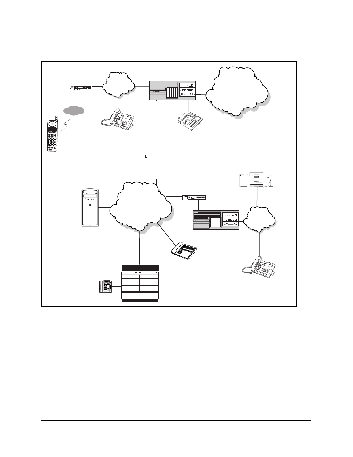
The following figure shows components of a Business Communications Manager network
configuration.
In this example, two Business Communications Manager systems are connected both through a
PSTN connection and through a WAN connection. The WAN connection uses VoIP trunks. If the
PSTN connections use dedicate d ISDN lines, the two systems have backup private networks to
each other. Both Business Communications Manager systems use VoIP trunks through a common
WAN to conn ect to the M eri d ian (M1 -IP T ) syst em .
IP Telephony Configuration Guide
Page 24
24 Chapter 1 Introduction
Inspect FORWARD Callers
MXP
Figure 1 Network diagram
Router
Access Point
Business Communications
Manager A
LAN A
PSTN
SND
FCTMENU
END
NAMERCL
ABC3DEF
1 2
JKL4GHI6MNO
5
TUV7PQRS9WXYZ
8
OPR
<#>
0
(H 323 device A)
STOCLR
HOLD
NetVision
Gatekeeper
IP telephone A
WAN
M1+IPT
Digital telephone A
Router
Business Communications
Manager B
I
n
s
p
e
c
t
F
O
R
W
A
R
D
C
a
ll
e
r
s
M
X
P
H 323 Device B
I2050 telephone A
LAN B
IP telephone B
Meridian set A
Networking with Business Communications Manager
The Business Communications Manager is a key building block in creating your communications
network. It interoperates with many devices, including the Meridian 1 system and H.323 devices.
The Business Communications Manager system can be connected to devices through multiple IP
networks, as well a s throug h the PSTN. Multiple Busine ss Communicat ions Manage r syst ems also
can be linked together on a network of VoIP trunks and/o r dedicated physical lines. Refer to
Chapter 8, “Typical network applications using MCDN,” on page 147.
The Business Communications Manager can be connected to a LAN through a LAN card, to a
WAN through a WAN card, and to a PSTN through trunk media bay modules, as shown for
Business Communications Manag er A in the above diagram. Through these networks, the syste m
accesses other syste ms and network eq uipment connected to the network.
P0609327 02
Page 25

Chapter 1 Introduction 25
M1-IPT
The Meridian 1 Internet Telephony Path (M1-IPT) allows Meridian 1 systems to communicate
with the Business Communications Manager via H.323 trunks. Telephones on the M1, such as
Meridian telephone A, can init iate and recei ve calls with the other telephon es on the system across
IP networks.
To provide fallbac k at times when IP traffic cannot pass, you can also connect the Meridi an to the
Business Communications Manag ers through ISDN PRI SL-1 lines, which provide the same
MCDN capability that you can achieve through the H.323 VoIP trunks with MCDN active.
Refer to the Programming Operations Guide for a description of MCDN features and networking
with PRI SL-1 lines. “Typical network applications using MCDN” on page 147 describes how to
provide the same network over VoIP lines.
A Business Communications Manager connected to an M1-IPT using the MCDN protocol can
provide access to a central voice mail and call attendant systems, which can streamline
multi-office telephony administration.
Telephones
The Business Communications Manager can communic ate using digital telephones (Model 7000,
7100, 7208, T7316, T7316E/T73 16E+KIMs, M7310(N) , M7324(N)), T7406 (cordle ss tele phone),
wireless telephone s (Companion, DECT), IP telephones and appli cations (i-series 200X and the
Nortel Networks i2050 Softwar e Phone), and IP wireless telephones (NetVision and NetVision
Data telephones). With this much flexibility, the Business Communications Manager can provide
the type of service you require to be most prod uct ive in your business.
While analog and digital tel ephones cannot be connected to the Business Communica tions
Manager system with an IP conne ction, they can make and receive calls to a nd from other systems
through VoIP trunks. Calls received through the VoIP trunks to system telephone s are received
through the LAN or WAN card and are translated within the Business Communications Manager
to voice channels.
The IP telephones connect to the Business Communications Manager across an IP network
through either a LAN or a WAN. From the Business Communications Manager connection, they
can then use standard lines or VoIP trunks to communicate to other telephones on other public or
private networks. The Business Communications Manager also supports H.323 (version 4) and
H.323 third-party devices through this type of connection.
Gatekeepers on the network
A gatekeeper tracks IP addresses of specified devices, and provides routing and (optionally)
authorizatio n for making and acce pting calls f or thes e devices. A gate keeper is not required a s part
of the network to which your Business Communications Manager system is attached, but
Gatekeepers can be useful on networks with a large number of devices. Referring to Figure 1 on
page 24, for example: Digital tele phone A wants to call IP telephone B, which is attached to
Business Communications Manag er B, over a network that is under the control of a gatekeeper.
IP Telephony Configuration Guide
Page 26

26 Chapter 1 Introduction
Digital telephone A sends a request to the gatekeeper. The gatekeeper, depending on how it is
programmed, provides Digital telephone A with the information it need s to contac t BC M B over
the network. Business Communications Manager B then passes the call to IP telephone B. SIP
trunks do not use gatekeepers.
The Business Communicati ons Manager does not contain a gatekeeper application. If you want to
put a gatekeeper on your network, it must be put on a separate gatekeeper server. The Business
Communications Manager is compatible with RadV ision, CSE 1000 (CSE1K), and NetCentrex
gatekeepers. Refer to “Using a gatekeeper” on page 133 and Appendix D, “Interoperability,” on
page 175.
Warning: Meridian 1 IP T does not support the RadVision gatekeeper.
IP network
In the network shown in Figure 1 on page 24, several LANs and a WAN are shown. When
planning your network, be sure to consider all requirements for a data network. Your network
administrator should be able to advise you about the network setup and how the Business
Communications Manager fits into the network.
WAN
A Wide Area Network (WAN) is a communications network that covers a wide geographic area,
such as state or country. For Business Communications Manager, a WAN is any IP network
connected to a WAN card on the Business Communications Manager system. This may also be a
direct connection to another Business Communications Manager system.
If you want to deploy IP telephones or NetVision te lephones that will be connected to a LAN
outside of the LAN that the Business Communica tions Mana ger is installed on, you must ensure
the Business Communication s Manager has a WAN connection. This includes ensuring that you
obtain IP ad dresses and routin g information that allows the remote telephones to find the Busi ness
Communications Manager, and vice versa.
The Programming Operations Guide has a data section that describes the internet protocols and
data settings that the Business Communications Manager requires or is compatible with. Ensure
that this connectio n is correctly set up and working before you attempt to deploy any remote IP
devices.
LAN
A Local Area Network (LAN) is a communications network that serves users within a confined
geographical are a. For Business Communi cati ons Manager, a LAN is any I P network conne cte d to
a LAN card on the Business Communications Manager system. Often, the LAN can include a
router that forms a connection to the Internet. A Business Communications Manager can have up
to two LAN connections.
P0609327 02
Page 27

Public Switched Telephone Network
The Public Switched Telephone Network (PSTN) can play an important role in IP telephony
communications. In many installations, the PSTN forms a fallback route. If a call across a VoIP
trunk does not have adequate voic e qualit y, th e call c an be rout ed across PSTN li nes instead, eit her
on public lines or on a dedicated ISDN connection between the two systems (private network).
The Business Communicat ions Manager also serves as a gate way to the PSTN for all voice tra ffic
on the system.
Key IP telephony c onc e pts
In traditional tele phony, the voice path between two telephones is cir cuit switched. This means
that the analog or digital connection betwe en the two telephones is dedic ated to the call. The voice
quality is usually excellent, since there is no other signal to inte rfere.
In IP telephony, each IP telephone encodes the speech at the handset microphone into small data
packets called frames. The system sends the frames across the IP network to the other tele phone ,
where the frames are decoded and played at the handset receiver. If some of the frames get lost
while in transit, or are delayed too long, the receiving telephone experiences poor voice quality.
On a properly-configured network, voice quality should be consistent for all IP calls.
Chapter 1 Introduction 27
The information under the following headings describe some of the components that determine
voice quality for IP telephone s an d trunks:
• “Codecs” on page 27
• “Jitter Buffer” on page 28
• “QoS routing” on page 29
Codecs
The algorithm used to compress and decompr ess voice is embedded in a software entity called a
codec (COde-DECode).
Two popular Codecs are G.711 and G.729. The G.711 Codec samples voice at 64 kilobits per
second (kbps) while G.729 samples at a far lower rate of 8 kbps. For actual bandwidth
requiremen ts , refe r to “Determining the bandwidth requirements” on page 153, where you will
note that the actual kbps requi rements are slightly higher than lab el sugg ests.
Voice quality is better when using a G.711 CODEC, but more network bandwidth is used to
exchange the voice frames between the telephones.
If you experience poor voice quality, and suspect it is due to heavy network traffic, you can get
better voice qualit y by configuring the IP telephone to use a G.729 CODEC.
Note: You can only change the codec on a configured IP telephone if it is online to the Business
Communications Manager, or if Keep DN Alive is enabled for an offline telephone.
IP Telephony Configuration Guide
Page 28

28 Chapter 1 Introduction
The Business Communications Manager supports these codecs:
• G.729
• G.723
• G.729 with VAD (Voice Activity Detection)
• G.723 with VAD
• G.711-uLaw
• G.711-aLaw
Jitter Buffer
Voice frames are transmitted at a fixed rate, because the time interval between frames is constant.
If the frames arrive at the other end at the same rate , voic e quality is perceived as good. In many
cases, however, some frame s can arrive slightl y faster or slower than the o the r fram es . Th is is
called jitte r, and degrades the perceive d voice quality. To minimize this problem, config ure the IP
telephone with a jitter buffer for arriving frames.
Note: You can only change the jitter buffer on a configured IP tel ephone if it is online to the
Business Communications Manag er, or if Keep DN Alive is enabled for an offline telephone.
This is how the jitter buffer works:
Assume a jitter buffer sett ing of five frames.
• The IP telephone firmware places the first five arriving frames in the jitter buffer.
• When frame six arrives, the IP telephone firmware places it in the buffer, and sends frame one
to the handset speaker.
• When frame seven arrives, the IP tele phone buffers it, and sends frame two to the handset
speaker.
The net effect of using a jitter buf fer is that the arriving packets are delayed slightly in order to
ensure a constant rate of arriving frames at the handset speaker.
This delaying of packets can provide somewhat of a communications challenge, as speech is
delayed by the number of frames in the buffer. For one -sided conversations, there are no issues.
However, for two-sided conversations, where one party tries to interrupt the other speaking party,
it can be annoying. In this second situation, by the time the voice of the interrupter reaches the
interruptee, the inte rrupte e has spoke n (2*jitt er si ze) frames pa st t he intende d poin t of inter ruption .
In cases where very large jitter sizes are used, some users revert to saying OVER when they wish
the other party to speak.
Possible jitter buffer settings, and corresponding voice packet latency (delay) for the Business
Communications Manager syst em IP telephones are:
• None
• Small (G.723: .06 seconds; G.711/G.729: .05 seconds)
• Medium (G.723: .12 seconds; G711/G.729: .09 seconds)
P0609327 02
Page 29

Chapter 1 Introduction 29
• Large (G.723: .18 seconds; G711/G.729: .15 seconds)
QoS routing
To minimize voice jitt er over low bandwi dth connecti ons, the Business Communic ations Mana ger
programming assigns spec ific DiffServ Marking in the IPv4 header of the data packets sent from
IP telephones.
Warning: BCM version 3.5 and newer software only supports H.323 ve rs ion 4. To
support this, all Business Communications Managers running BCM version 3.0. 1 or
earlier software, which are on a network with a Business Communications Manager
running BCM version 3.5 or newer software, must either be upgra ded to BCM version 3.5
or newer software or apply a QoS patch (3.0.0.25 or late r) to support thi s versio n of H.323.
The DiffServ Code point (DSCP) is c ontained in th e sec ond byte of the IPv 4 header. DSCP is used
by the router to determine how the packets will be separated for Per Hop Behavior (PHB). The
DSCP is contained within the Dif fServ field, which was known as the ToS field in older versions.
The Business Communicati ons Manager assig ns Expe dited Forwar ding (EF) PHB for voice medi a
packets and the Class Selector 5 (CS5) PHB for voice signal ing (control ) packets. On the Business
Communications Manager, these assignments cannot be adjusted.
The Business Communi cations Manager system performs QOS routing, but if one or more routers
along the network route do not support QOS routing, this can impact voice quality. Business
Communications Manager system QoS can also be configured so that the system reverts to a
circuit-swit ched line if a suitable QoS cannot be guaranteed.
IP Telephony Configuration Guide
Page 30

30 Chapter 1 Introduction
P0609327 02
Page 31

Chapter 2
Prerequisites checklist
Before you set up voice over IP (VoIP) trunks or IP telephones on a Business Communications
Manager, complete the follo wing checklists to ensure that the system is corr ectly set up for IP
telephony. Some questions do not apply to all installations.
This guide contains a number of appendice s tha t e xplain various aspects of IP networking dire ctly
related to IP telephony func tions. Refer to the Programming Operations Guide for specific
information about configuring the data portion of the Business Communications Manager.
This section includes the following checklists:
• “Network diagram” on page 31
• “Network devices” on page 32
• “Network assessment” on page 33
• “Resource assessment” on page 33
• “Keycodes” on page 34
• “System configuration for IP fun ctions” on page 34
• “Finding the published IP addres s” on page 35
• “Media gateway parameters for IP service” on page 37
• “VoIP trunks” on page 39
• “IP telephone records” on page 40
31
Network diagra m
To aid in installation, a Network Diagram provides a basic understanding of how the network is
configured. Before you install IP functionality, create a network diagram that captures all of the
information describe d in the following table. If you are configuring IP telephones but not voice
over IP (VoIP) trunks, you do not need to answer the last questions 1.d or 1.e.
Table 1 Network diagram prerequisites
Prerequisites Yes
1.a Has a network diagram been developed?
1.b Does the network diagram contain any routers, switches or bridges with corresponding
IP addresses and bandwidth values for WAN or LAN links?
Also refer to Appendix D, “Interoperability,” on page 175.
1.c Does the network diagram contain IP Addresses, netmasks, and network locations of all
Business Communications Managers?
1.d Answer this if your system will use IP trunks, otherwise, leave it blank: Does the network
diagram contain IP Addresses and netmasks of any other VoIP gateways that you need to
connect to?
IP Telephony Configuration Guide
Page 32

32 Chapter 2 Prerequisites checklist
Table 1 Network diagram prerequisites (Continued)
Prerequisites Yes
1.e Answer this only if your system will use a gatekeeper, otherwise, leave it blank: Does the
network diagram contain the IP address for any Gatekeeper that may be used?
Note: If the network has a Meridian 1 running IPT software, you cannot use a RadVision
gatekeeper.
Network devices
The following table contains questions about devices on the network such as firewalls, NAT
devices, and DHCP servers.
• If the network uses public IP addresses, complete 2.d.
• If the network uses private IP addresses, complete 2.e. to 2.f.
Table 2 Network device checklist
Prerequisites Yes No
2.a Is the network using DHCP?
2.b If so, are you using the DHCP server on the Business Communications
Manager?
2.c Is the network using private IP addresses?
2.d Are there enough public IP addresses to accommodate all IP telephones and the
Business Communications Manager?
2.e Does the system have a firewall/NAT device, or will the Business
Communications Manager be used as a firewall/NAT device?
NOTE: NetVision handsets do not work on a network that has NAT between the handset
and the system.
2.f If the Business Communications Manager is to be used as a firewall/NAT device,
do the firewall rules fit within the 32 input rules and 32 output rules that the
Business Communications Manager provides?
2.g A hub-based core will not have suitable performance for IP Telephony. Does the
network use a non-hub solution at its core?
P0609327 02
Page 33

Chapter 2 Prerequisites checklist 33
Network assessment
The following table questions are meant to ensure that the network is capable of handling IP
telephony, and that existing network services are not adversely affected.
Table 3 Network assessment
Prerequisites Yes No
3.a Has a network assessment been completed?
3.b Has the number of switch/hub ports available and used in the LAN infrastructure
been calculated?
3.c Does the switch use VLANs? If so, get the VLAN port number and ID.
3.d Have the used and available IP addresses for each LAN segment been
calculated?
3.e Has DHCP usage and location been recorded?
3.f Has the speed and configuration of the LAN been calculated?
3.g Has the estimated latency values between network locations been calculated?
3.h Have the Bandwidth/CIR utilization values for all WAN links been calculated?
3.i Has the quality of service availability on the network been calculated?
Resource assessment
Answer the questions in the followi ng table to determine if you have allocated suff icie nt resources
on the Business Communications Manager for IP telephony.
For information about changing the DS30 split for the Business Communications Manager and
allocating media resources, refer to the Programming Operations Guide (dat a sections) .
Hardware restriction: IP telephony, including T.38 fax, cannot operate on a system that has
PEC Is installed on the MSC. Your system must have PEC IIIs.
Table 4 Resource assessment
Prerequisites Yes No
4.a Has a Business Communications Manager Resource Assessment been
performed using the resource questionnaire in the Programming Op erations
Guide?
4.b Has an analysis been done to determine which DS30 split is appropriate for the
system? Has the DS30 split been changed to 3/5, if necessary?
4.c Have all necessary media resources for IP trunks, clients, vmail, IP music, or
WAN dialup been assigned or dedicated?
IP Telephony Configuration Guide
Page 34

34 Chapter 2 Prerequisites checklist
Keycodes
All elements of VoIP trunks and IP telephony are locked by the Business Communications
Manager keycode sy stem. You can purchase keycodes for the amount of access you want for your
system. Additional keycodes can be added later, providing there are adequate resources to handle
them.
Table 5 Keycodes
Prerequisites Yes No
5.a Complete this question only if you are using VoIP trunks: Do you have enough
VoIP keycodes? Both H.323 trunks and SIP trunks use VoIP keycodes.
5.b Complete this question only if you are using IP telephones: Do you have enough
IP client keycodes? (Note: IP clients and IP telephones are a 1:1 ratio. Include
any NetVision telephones to your calculations. As soon as an IP telephone is
registered, it occupies an IP client, whether it is active or not.).
5.c If you are using VoIP trunks, do you need to activate MCDN features?
Note: If MCDN is already configured on your system for private networking over
PSTN lines, you do not need a separate MCDN keycode for VoIP trunks.
SIP trunks do not support the MCDN protocol.
System configuration for IP functions
Several sections of the Business Communications Manager must be properly configured prior to
activation of IP telephony. Answer the questions in the following table to determine if your
Business Communications Manag er has been correctly configured.
Table 6 Business Communications Manager system configuration
Prerequisites Yes No
6.a Is the LAN functioning correctly with the Business Communications
Manager?
6.b Is the WAN functioning correctly with the Business Communications
Manager?
6.c Have you determined the published IP address for the system? Refer to
“Finding the published IP address” on page 35.
6.d Have the necessary media gateway, IP client, and IP trunks resources been
set? (Refer to “Media gateway parameters for IP service”.)
6.e Has a dialing plan been created, taking into account special considerations
for IP telephony and private and public networking?
P0609327 02
Page 35

Finding the published IP address
The published IP address is the IP address use d by computers on the public network to find the
Business Communications Manag er. For example, if a Business Communications Manager has a
LAN interface (LAN1) that is connected only to local office IP terminals and a WAN interface
(WAN1) that is connected to the public net work, then WAN1 should be set to the published IP
address.
Setting the Global IP (published IP)
To set the published IP address:
1 In Unified Manager, click on the keys beside Services and IP T elephony.
2 Click IP Terminals.
The Global IP Setting tab appears, as shown in the diagram below.
Figure 2 Global IP settings
Chapter 2 Prerequisites checklist 35
3 From the Publis he d IP A dd ress menu, select the appropriate network interfa ce.
Table 7 Published IP Address options
Option Description
IP-LAN1 Choose the LAN number that corresponds with the LAN
IP-LAN 2
IP-WAN1 Choose the WAN number that corresponds with the WAN
IP-WAN2
IP-UTWAN1 If you are using a WAN connection using a Universal T1
card you are using for this network.
card you are using for this network.
line, choose this option.
IP Telephony Configuration Guide
Page 36

36 Chapter 2 Prerequisites checklist
Determining the published IP address
Use the flowchart in the follo wing f igure to de termine whic h card sh ould be se t as the publ ishe d IP
address.
Figure 3 Selecting the Published IP address
Start
Is NAT enabled?
Y
Is the Business Communications
Manager expected to connect to
devices on the public side?
Y
Are all of your public side
devices using a VPN?
Y
Do you anticipate the most
VOIP traffic on your public
or private side?
Private
Set the network interface on the
private side as the published
IP address
N
N
N
Public
Set the network interface with
the most anticipated VoIP traffic
as the Published IP address
Set the network interface on the
private side as the published
IP address
Set the network interface on the
public side as the published
IP address
Set the network interface on the
public side as the published
IP address
The flowchart shown above makes reference to public and private IP addresses. The public and
private IP addresses are conce pts relating to Network Address Translation (NAT). The decision
also depends on whe ther a Virtual Private Network (VP N) is enabled. For information about NAT
and VPN, refer to the Programming Operations Guide.
If you use IP telephones on the network, they must be set to have the IP address of the network
card they are con nect ed to for thei r Default Gateway , and the Publ is h ed IP ad dr ess as the S1 IP
address. For more information about this, refer “Configurin g the i20XX telephones to the system”
on page 47.
P0609327 02
Page 37

Chapter 2 Prerequisites checklist 37
Media gateway parameters for IP service
To set up the media gateway resources that you require for optimum IP telephony and VoIP trunk
service, you need to define some basic gateway parameters. These parameters are set in the
System Configuration window.
Follow these steps to config ure the media gateway:
1 Click the Services and IP Telephony keys.
2 Click System C onfi g ur a tion.
The Parameters screen appears in the right frame.
Figure 4 System Configuration, Parameters screen
3 Change the settings for the fields below, as required for your system.
Table 8 IP terminals general record fields
Field Value Description
Echo Cancellation Enabled w/NLP
Enabled
Disabled
Enable or disable echo cancellation for your system.
Default: Enabled w/NLP (check with your internet system
administrator before changing this)
Echo Cancellation selects what type of echo cancellation is
used on calls that go through a Media Gateway. NLP refers to
Non-Linear Processing.
IP Telephony Configuration Guide
Page 38

38 Chapter 2 Prerequisites checklist
Table 8 IP terminals general record fields (Continued)
Field Value Description
G.723.1 Data Rate 5.3 kbps
6.3 kbps
T.38 UDP
0, 1, 2, 3 If T.38 fax is enabled on the system, this setting defines how
Redundancy
Reserved Media
Gateway Codec
G.711
G.729
G.723
Choose the preferred data rate for the channel.
G.723.1 Data Rate selects what data rate is used for
transmissions from the Business Communications Manager to
an IP device when the G.723.1-family codec is used (G.723.1
or G.723.1A). This has no effect on any other codec. The
possible values are 5.3 kbps and 6.3 kbps.
many times the message is resent during a transmission in
order to avoid errors caused by lost T.38 messages.
Default: 0
Choose the preferred codec that you are using with your IP
network.
Reserved Media Gateway Codec should be set to whatever
is the most-commonly used codec for Media Gateways. It
determines the amount of codec resources reserved for each
Media Gateway. Reserving resources speeds up
establishment of connections. For example, if most calls
through a Media Gateway use the G.711 codec, set this to
G.711. If most calls use G.729, set this to G.729. Note that the
higher the setting (G.723 > G.729 > G.711) the more
resources are set aside for Media Gateways. This may result
in calls failing to go through because of lack of available
resources.
T.38 UDP
Redundancy
0-3 Default: 0 (transmitted only once)
This setting defines the number of times the system will
transmit a UDP packet over the network. This setting acts as
an error control mechanism for unreliable networks by
providing the same information more than once, with the
intention that at least one of the copies will transmit correctly.
WARNING: Each redundancy requires the same amount of
bandwidth as the original message. This means that a
redundancy of 3 requires four times the bandwidth of a single
transmission.
For a more detailed descriptions of the media gateway or other information about the media services card
(MSC) settings for the Business Communications Manager, refer to the Programming Operations Guide,
MSC section.
P0609327 02
Page 39

Chapter 2 Prerequisites checklist 39
VoIP trunks
Complete this section if you are configur ing VoIP trunks.
Table 9 VoIP trunk provisioning
Prerequisites Yes No
7.a Have you confirmed the remote gateway or Gatekeeper settings and access
codes required? (H.323 and SIP trunks).
7.b Have you determined the preferred codecs and payload sizes required for each
type of trunk and destination?
7.c Have you determined how you are going to split your VoIP resources between
H.323 and SIP trunks.
7.d Have you set up line parameters, determined line pools for H.323 and/or SIP
trunks, and set up routing and destination codes? Have you determined which
system telephones will have access to these routes?
7.e If you have not already assigned target lines, have you defined how you are going
to distribute them on your system?
7.f Have you decided if you are going to employ the fallback feature?
If yes, ensure that your routing and scheduling are set up. Ensure that QoS is
activated.
Network note: If your Business Communications Manager is part of a private
network, have the other Business Communications Managers in the network
been upgraded to BCM 3.5 or newer software or had QoS patch 3.0.0.25 (or
later) applied?
If there is a Meridian 1 on the network, is it running IPT 3.0 or newer?
If either of these conditions are not met, your H.323 trunks will not work correctly.
Refer to “Configuring local VoIP trunks” on page 85, “Setting up VoIP trunks for outgoing calls” on page
101, and “Optional VoIP trunk configurations” on page 129 for detailed configurations.
IP Telephony Configuration Guide
Page 40

40 Chapter 2 Prerequisites checklist
IP teleph one r e co r ds
Complete this section if you are installing i-series and/or NetVision telephones.
Table 10 IP telephone provisioning
Prerequisites Yes No
8.a Are IP connections and IP addresses available for all IP telephones? If you want
the telephone to have access to a Net6 content provider server, have you also
obtained the IP address for that server?
8.b If DHCP is not being used, has all telephone configuration been documented and
made available for telephone installers?
Hint: Use the Programming Record form.
Note: If you are registering NetVision handsets to a system running DHCP, ensure that
you first enter a static IP list for all the handsets you intend to register.
8.c If DHCP is not being used, or if you want to enter the port manually, has the
VLAN port number been supplied, if one is being used on the switch?
8.d Have you determined the default codecs (and payload sizes), and default jitter
buffers required by the IP network that supports the telephone?
8.e Have telephone power and connectors been provisioned?
8.f Do computers that will be using the Nortel Networks i2050 Software Phone meet
the minimum system requirements, including headset?
8.g Do you want the system to auto-assign DNs (i-series telephones)? If no,
complete 8.h.
Note: If your company is using the Call Center application on the Business
Communications Manager, Nortel recommends that you manually assign DNs to
avoid conflicts with Call Center DN assignments.
8.h Have DN records been programmed for the corresponding IP clients? (use when
manually assigning DNs to the telephones)
8.i NetVision handsets: Have you obtained the current NetVision Phone
Administrator application from the Symbol web site and filled out the required
information and determined what features will be added or deleted from the
feature list? Refer to the NetVision Phone Administrator Guide on your Business
Communications Manager documentation CD or off the Symbol web site.
Do you have the necessary serial cable to perform the upload of handset
information to the Business Communications Manager.
i-series telephones: Refer to Chapter 3, “Installing IP telephones,” on page 41
NetVision wireless handsets: Refer to Chapter 4, “Installing NetVision telephones,”
on page 73
P0609327 02
Page 41

Chapter 3
Installing IP telephones
An IP telephone converts the voic e signal into data packets and sends these packets directly to
another IP telephone or to the Business Communications Manager over the LAN or the internet.
• If the dest ination is an IP telephone, the arriving voice packe ts are converted t o a voice stream
and are routed to the speaker or headset of the target telephone.
• If the destination is the Business Communications Manager, the voice strea m is routed to a
circuit switched con nection, such as a telephone (internal ) or line (external PSTN or private
network), or some form of gateway (VoIP).
Note: IP telephones require an IP network to reach the Business Communications Manager.
However, they do not need to use VoIP trunks to communicate beyond the Business
Communications Manager. They can use any type of trunk in the same way that digital telephones
do.
Before setting up IP clients, you must enable keycodes for IP telephony. For information about
entering IP Client keycodes, see the Keycode Installation Guide. Each IP Client keycode opens a
specific number of IP t elephone cha nnels on the syste m. Channels on the MSC are dist ributed on a
one-to-one basis as each IP tel ephone or NetVision handset registers with the system.
41
Detailed information about installing i20XX IP telephones is contained under the following
headings:
• “IP telephony on the Business Communicati ons Manager” on page 42
• “Configuring Nortel Networks i-series telephones” on page 42
• “Configuring DHCP” on page 53
• “Modifying IP telephone statu s settings” on page 57
• “Working with the features list” on page 59
• “Resetting the Hot Desking password” on page 61
• “Download firmware to a Nortel IP telephone” on page 65
• “Deregistering DNs for IP telephones” on page 66
• “Moving IP telephones” on page 69
• “Configuring a new time zone on a remote telephone” on page 70
• “Nortel Networks i2050 Software Phone” on page 71
IP Telephony Configuration Guide
Page 42

42 Chapter 3 Installing IP telephones
IP telephony on the Business Communications Manager
The Business Communications Manager supports IP telephony protocols, UNISTIM and
H.323 ( version 4).
• The Nortel Networks i-seri es telephones use the UNISTIM protocol.
• The Symbol NetVision and NetVision Data tele phones use H.323. Refer to Chapter 4,
“Installing NetVi sion telephones,” on page 73.
The applications that co ntrol these protocols on the Business Communica tions Manager provide
an invisible inter face between the IP telephones and the digital voice processing controls on the
Business Communications Manag er.
The i200X IP telephones are hardwir ed to an inte rnet connection. They can be installe d on any
internet connect ion that has access to the network connected to the LAN or WAN of the Business
Communications Manager.
The Nortel Net works i20 50 Soft ware Phone runs o n any c omputer running Win dows 98, Windows
2000, or Windows XP. The computer must be connected to the LAN or WAN to which the
Business Communications Manag er is connected.
Configuring Nortel Networks i-series telephones
The configuration menus for the Nortel Networks IP telephones are located under Services, IP
Telephon y, N o rte l IP Te rmi na ls and Services, Telephony Services, System DNs, Inactive
DNs, Set DNs. DN records move to Active set DNs after the telephone connects (registers) to the
system.
Once a DN record is assigned and the telephone registers to the system, the record also shows up
under DN Registration in one of the fol lowing folders:
• Inactive DNs reg’ d if the IP tele phone has been assigned a DN and is registere d to the system
but currently is not acti ve
• IP set DNs reg’d if the IP telephone is active
• IP wireless DN s re g’d if the NetVision handset is regi stered and is active
The information under the following headings provides details about configuring and
troubleshooting IP telephones:
• “Preparing your system for IP telep hone registration” on page 43
• “Installing i-series telephones” on page 46
• “Configuring the i20XX telephon es to the system” on page 47
• “Troubleshooting IP tele phones” on page 51
P0609327 02
Page 43

Chapter 3 Installing IP telephones 43
Preparing your system for IP telephone registration
When you install an IP telephone on a Business Communications Manager, you must activate
terminal registra tion on the Business Communications Manager. If this is your first installati on,
you need to set the ge neral parameter s for IP regi s trat i on.
For the simplest instal lation possible, set telephone Registration and
Auto Assign DNs to ON, and leave the Password field blank. IP telephones insta lled on the
system LAN will connect and boot-up without manual registration.
Security N o te: Turn Registration and Auto Assign DNs off once the telephone(s) are
registered. Nortel cautions that leaving your IP registration open and unprotected by a
!
password may pose a security risk.
Caution: DN auto assign: Call Center DNs (CDNs) and IP telephones share a common
DN database. If you use auto assign to assign DNs to your IP telephones, the system can
inadvertentl y assign an IP telephone to a DN within the CDN range. CDNs do not register
to the syste m, so the system has no way of knowing tha t the DN is alr eady assigned. If this
happens, you can rename the IP DN to a DN outside the CDN range and reenter the CDN
information.
Setting IP terminal general settings
1 In Unified Manager, open Services, IP Telephony, IP Terminals and Nortel IP Terminals.
2 Select the General tab.
The General screen appears.
Figure 5 Set registration properties
IP Telephony Configuration Guide
Page 44

44 Chapter 3 Installing IP telephones
3 Use the information in the table below to set up your IP terminals general information.
Ta ble 1 1 IP terminals general record fields
Field Value Description
Registration On
Off
Password <10 alphanumeric>
Default: bcmi
Auto Assign DN On
Off
Advertisement/Logo <alphanumeric
string>
Default Codec Auto
G.711-aLaw
G.711-uLaw
G.729
G723
G.729 + VAD
G.723 + VAD
Set this value to ON to allow new IP clients to register with
the system.
WARNING: Remember to set Registration to Off when you
have finished registering the new telephones.
This is the password the installer will enter on the IP
telephone to connect to the Business Communications
Manager.
If this field is left blank, no password prompt occurs during
registration.
If set to ON, the system assigns an available DN as an IP
terminal requests registration. It does not prompt the installer
to enter a set DN. Note: For this feature to work,
Registration must be ON and Password must be blank
If set to OFF, the installer receives a prompt to enter the
assigned DN during the programming session.
Note: Refer to the Caution notice at the top of this section.
Any information in this field appears on the display of all IP
telephones. For example, your company name or slogan.
If the IP telephone has not been configured with a preferred
codec, choose a specific codec that the IP telephone will use
when it connects to the system.
If you choose Auto , the IP telephone selects the codec.
For information about choosing a codec, refer to “Choosing a
codec” on page 45.
If you are unsure about applying a specific codec, ask your
network administrator for guidance.
Default Jitter Buffer None
Auto
Small
Medium
Large
P0609327 02
Choose one of these settings to change the default jitter
buffer size:
• NONE: Minimal latency, best for short-haul networks
with good bandwidth.
• AUTO: Business Communications Manager will
dynamically adjust the size.
• SMALL: Business Communications Manager will adjust
the buffer size, depending on CODEC type and
number of frames per packet to introduce a
60-millisecond delay.
• MEDIUM: 120-millisecond delay
• LARGE: 180-millisecond delay
For information about choosing a Jitter Buffer, refer to
“Choosing a Jitter Buffer” on page 46.
Page 45

Ta ble 1 1 IP terminals general record fields (Continued)
Field Value Description
Chapter 3 Installing IP telephones 45
G.729 Payload Size
(ms)
G.723 Payload Size
(ms)
G.711 Payload Size
(ms)
4 Go to “Installing i-series telephones” on page 46.
Choosing a codec
The default codec is used when an IP client has not been configured to use a preferred Codec.
Refer to the next section for individual IP client Codec settings. I f the defa ult Codec is set to
AUTO, the Business Communications Manager will choose the appropriate CODEC when an IP
client makes a call. F or example , if both endp oints of the c all a re IP te lephones on the same subnet,
the Business Communication s Manager chooses G.711 for maximum voice quality. If the
telephones are on different subnets, the Business Communications Manager will choose G.729 to
minimize network bandwidth con sumption by voice data packets.
Note: If the IP tele phones are using VoIP tr unks for the call, the codec set for the trunks overrides
the telephone settings.
10, 20, 30, 40, 50,
60
Default: 30
30
10, 20, 30, 40, 50,
60
Default: 20
Set the maximum required payload size, per codec, for the IP
telephone calls sent over H.323 trunks.
Note: Payload size can also be set for Nortel IP trunks. Refer
to “Configuring media parameters” on page 89.
For IP telephones, the Business Communications Manager supports both a-law and mu-law
variants of the G.711 CODEC, as well as the G.729 and G.723 CODECS.
• The G.711 CODEC samples the voice stream at a rate of 64Kbps (Kilo bit s per second ), and is
the CODEC to use for maximum voice quality. Choose the G.711 CODEC with the
companding law (alaw or ulaw) that match es your syste m requirements.
• The G.729 CODEC samples the voice stream at 8Kbps. The voice quality is slightly lower
using a G.729 but it reduces network traffic by approximately 80%.
• The G.723 CODEC should be used only with third party devices that do not support G.729 or
G.711.
• Codecs with VAD (Voice Activity Detection) make VAD active on the system, which
performs the same function as having silence suppression active.
Note: You can only change the codec on a configured IP telepho ne if it is online to the Business
Communications Manager, or if Keep DN Alive is enabled for an offline te lephone.
IP Telephony Configuration Guide
Page 46

46 Chapter 3 Installing IP telephones
Choosing a Jitter Buffer
A jitter buffer is used to prevent the jitter associated with arriving (Rx) voice packets at the IP
telephones. The jitter is caused by pac kets arriving out of order due to having used different
network paths, and varying arrival rates of consecutive voice packets.The greater the size of the
jitter buffer, the better sounding the received voice appears to be. However, voice latency (delay)
also increases. Latency is very problematic for telephone calls, as it increases the time between
when one user speaks and when the user at the other end hears the voice.
Note: You can only change the jitter buffer on a configured IP telephone if it is online to the
Business Communications Manag er, or if Keep DN Alive is enabled for an offline telephone.
Installing i-series telephones
The Nortel Networks i- serie s tele phones (i20XX) can be conf igure d to the networ k by t he end user
or by the admini strator . If th e end u ser i s configur ing the tele phone, t he admini strat or must pr ovide
the user with the required parameters.
A maximum of 90 IP telephones, including Nortel Networks i2050 Software Phones, and H.323
devices such as NetVision handsets, can be connected on the Business Communications Manager
system, if the system resources support the deployment.
Before installing
Before installing the i200X telephone, ensure that:
• the telephone has the appropriate power supply for your region
• if powered locally, the installation site has a nearby power outlet;
otherwise, it can be powered through a Power Inline Patch Panel (PiPP)
• the installation site has a 10/100 BaseT Ethernet connection
Caution: Do not plug the telepho ne into an ISDN connection. This can cause severe
damage to the telephone. Plug the telephone only into a 10/100 BaseT Ethernet
connection.
• if you are using an IP telephone that does not have a 3-port switch, ensure you have 10/100
BaseT Ethernet connections for both the telephone and for your computer equipment.
Using a 3-port switch
In an office environment where a LAN network already exists, most computers will already be
connected to a LAN line. To avoid the necessity of installing duplicate network connections, you
can use a Nortel Networks 3-po rt switch for older model i2004 telephones. This switch allows the
telephone and compu ter to co nnect t o the same ne twork conne ction. For more inf ormati on, consu lt
the i2004 setup card and the 3-way switch documentation.
P0609327 02
Page 47

Chapter 3 Installing IP telephones 47
The i2001, i2002, and newer models of the i2004 tele phone have an adapter in the telephone
housing that replace s the requ irement for this switch.
Connecting the i2 00X telephones
Follow these steps to connect a Nortel IP i200X telephone:
1 Connect one end of the handset cord to the handset jack on the telephone base.
2 Connect the other end of the handset cord to the handset.
3 Connect one end of a Cat-5 line cord with RJ45 connectors to the line cord jack on the
telephone base.
4 Connect the other end of the line cord to the Ethernet connection or to the 3-way switch
connector.
Note: Newer i200X terminals have a 3-way switch built into the telephone. Refer to the
installation card that comes with the telephone for specific connection directions.
5 Plug the AC Power adapter into the base of the telephone, and then plug the adapter into the
AC outlet.
Once the telephone is connected, refer to “Configuring the i20XX telephones to the system” .
Configuring the i20XX tel ephones to the system
Configuring Nortel IP telephones involves two processes:
• If DHCP (Distributed Host Control Protocol ) service on the Business Communicat ions
Manager is active or the Customer DHCP server has been configured to hand out the specific
Business Communicati ons Manager d etail s, the IP tel ephone will a utomatic ally a ttempt to f ind
the server. Refer to “Configuring DHCP” on page 53, which describes the specific DHCP
requirements for IP tele phones, and to the Programming Operations Guide, which provides
detailed DHCP configuration information.
After you register the telephone to the system, as described in “Registering the telephone to
the system”, the telephone assumes the parameters it receives from the system, which are
described in “Configuring tele phone settings”.
• If DHCP is not configured to provide system information, or if you are not using DHCP on
your network, you need to configure your telephone parameters before the telephone can
register to the system. In this case, follow the directions in “Configuring telephone settings”,
and then follow any of the prompts that appear, as described in “Registering the telephone to
the system”.
IP Telephony Configuration Guide
Page 48

48 Chapter 3 Installing IP telephones
Registering the telephone to the system
When you first connect the telephone to the IP connection, you may receive one of the following:
• If the telephone is not yet registe red, and if a password was entered in the Terminal
Registration scr een, the telephone prompts you for that password.
• If you set Auto Assign DN to OFF, the telephone prompts you for a DN. Refer to “Setting IP
terminal general settings” on page 43.
• If you are prompted for a password, enter the password and press OK
• If you are prompted for a DN, enter the DN you want assigned to this telephone and press OK
When the telephone registe rs, it downloads the information from the Business Communications
Manager IP Telephony record to the telephone configuration record. This might include a new
firmware download, which occurs automatically. If new firmware downloads, the telephone
display indicate s the event.
Note: If the telephone displays a prompt that indicates it cannot find the server, follow the
instructions in “Configuri ng telephone settings” to enter the specific network path.
“Troubleshooting I P telephones” on page 51 describes other possible prompt messages.
.
.
After registration is com plete, you do not ne ed to go through t he re gistrati on ste ps descri bed above
unless you deregister the terminal. For information about setting the registration settings, see
“Setting IP terminal gener al settings” on page 43.
Configuring te lephone settings
If you are not automatically registered to the Business Communications Manager, you can
configure your telephone settings to allow you to access a system on the network. You will also
need to perform these steps if your IP telephone is not connected to the same LAN to which the
Business Communications Manag er is connected.
Follow these steps to access the local configuration menu on an i200X telephone:
1 Restart the telephone by disconnecting the power, then reconnecting the power.
After about four seconds, the top light flashes and
2 When the greeting appears , immediately, an d qu ic kly , pre s s the fou r dis pl ay butto n s , one
at a time, from left to right. These buttons are located directly under the display.
NORTEL NETWORKS appears on the scree n.
Display buttons
P0609327 02
Page 49

Chapter 3 Installing IP telephones 49
Press the button sequence within 1.5 se conds or the telephone will not go into configur ation
mode.
Manual Cfg DHCP(0 no, 1 yes) appears on the scre en, you s uccessfully access ed the
• If
configuration mode.
• If any other message appears, disconnect, then reconnect the power, and try to access the
configuration mode again.
3 Enter the network parameters, as prompted.
As each parameter prompt appears, use the keypad to define values.
Use the * key to enter the period in the IP addresses.
OK to move forward.
Press
The following table describe s the values for each display parameter.
Table 12 IP telephone server configurations
Field Value Description
DHCP 0 or 1 Enter 0 if your network is not using a DHCP server to dispense
IP addresses. (Partial DHCP)
Enter 1 if your network does use a DHCP server.
If you choose to use a DHCP server rather than allocating static
IP addresses for the IP telephones, skip the remainder of this
section.
For information about setting up DHCP server information for
the IP telephones, see “Configuring DHCP” on page 53.
If DHCP = 0
SET IP <ip address> The set IP must be a valid and unused IP address on the
network that the telephone is connected to.
NETMASK <subnet mask
address>
DEF GW <ip address> Default Gateway on the network (i.e., the nearest router to the
This is the subnet mask. This setting is critical for locating the
system you want to connect to.
telephone. The router for IP address W.X.Y.Z is usually at
W.X.Y.1)
If there are no routers between the telephone and the Business
Communications Manager network adaptor to which it is
connected, (for example a direct HUB connection), then enter
the Published IP address of the Business Communications
Manager as the DEF GW.
If the IP telephone is not connected directly to the Published IP
address network adaptor, set the DEF GW to the IP address of
the network adaptor the telephone is connected to. For
information on setting the published IP address of the Business
Communications Manager, see “Finding the published IP
address” on page 35.
IP Telephony Configuration Guide
Page 50

50 Chapter 3 Installing IP telephones
Table 12 IP telephone server configurations (Continued)
Field Value Description
If DHCP = 1
Manual Cfg?
DHCP:
Full = 0
Partial = 1
If you indicate DHCP for the telephone, but you want to enter
static IP addresses, choose 1 (Partial).
If you choose 0 (Full), the DHCP server will assign IP addresses
that are not static.
If DHCP = 0 or Partial
S1 IP <ip address> This is the Published IP address of the first Business
Communications Manager that you want to register the
telephone to.
S1 PORT Default: *7000 This is the port the telephone will use to access this Business
Communications Manager.
S1 ACTION Default: 1
S1 RETRY COUNT <digits between 0
and 255>
Set this to the number of times you want the telephone to retry
the connection to the Business Communications Manager.
S2 IP <ip address> This is the Published IP address of the second Business
Communications Manager that you want to register the
telephone to. It can also be the same as the S1 setting.
S2 PORT Default: *7000 This is the port the telephone will use to access this Business
Communications Manager.
S2 ACTION Default: 1
S2 RETRY COUNT <digits between 0
and 255>
VLAN 0: No VLAN
1: Manual VLAN
2: Automatically
discover VLAN
using DHCP
Set this to the number of times you want the telephone to retry
the connection to the Business Communications Manager.
Choose 0:NO VLAN if there is no VLAN on the network.
If you do not have DHCP on the network, or if DHCP is supplied
by a remote server, select number 1 and enter the VLAN ID*.
If you have the Business Communications Manager DHCP
active on your system, select number 2 if you want DHCP to
automatically find the VLAN assignment. Refer to “Configuring
DHCP” on page 53.
*VLAN is a network routing feature provided by specific types of
switches. To find out if VLAN has been deployed on your
system, check with your network administrator. If VLAN is
deployed, the system administrator responsible for the switch
can provide the VLAN ID(s) for your system. Refer to the
Programming Operations Guide for information about VLAN
configuration and DHCP. Also refer to “Using VLAN on the
network” on page 181.
Cfg XAS? 0: No (default)
1: Yes
If you want the telephone to be able to connect to a Net6 service
provider server, choose 1. You will then be prompted for an IP
address for the server.
* Firewal l no te : Ensure that the firewall filters are set up to allow IP traffic into and out of the system. In
the Programming Operations Guide, refer to Configuring IP Firewall Filters for details.
P0609327 02
Page 51

Chapter 3 Installing IP telephones 51
After you have entered all the configuration information, the telephone attempts to connect to the
Business Communications Manag er. The message
the connection is successf ul, the message changes to
Locating Server appears on the display. If
Connecting to Server after about 15
seconds. Initialization may take several minutes. Do not disturb the telephone during this time.
When the telephone conn ects to the ser ver and is re ady to use , the displa y shows the tim e and date.
As well, the six keys at the top of the display are labe lled.
If you experience problems with IP telephone registration, r efe r to the section: “Troubleshooting
IP telephones”.
Notes:
• If the DN record has no t yet been configured, as will be the case with auto-a ssigned DNs, you
will only be able to make local calls, until other lines have been assigned in the DN record.
• If the telephone has not bee n registe red bef ore, you wi ll rece ive a New Set message. Enter the
information, as prompted. Refer to “Registering the telephone to the system” on page 48.
Troubleshooting IP telephones
If the system is not properly configured, several messages can appear.
Table 13 IP telephony display messages
Message Description/Solution
SERVER: NO PORTS LEFT The Business Communications Manager has run out of ports. This
message will remain on the display until a port becomes available and
the telephone is powered down then powered up.To obtain more ports,
you may need to install additional VoIP keycodes. See the Keycode
Installation Guide.
Invalid Server Address The S1 is incorrectly configured with the IP address of a Business
Communications Manager network adapter other than the published IP
address.
IP Address conflict The telephone detected that a device on the network is currently using
the IP address allocated to the telephone.
Registration Disabled The Registration on the Business Communications Manager is set to
OFF.
SERVER UNREACHABLE.
RESTARTING . . .
NEW SET The telephone has not been connected to the Business
Check that you have entered the correct Netmask and gateway IP
addresses.
If the settings are correct, contact your system administrator.
Communications Manager before, and must be registered.
Programming note: To see the configuration information for a telephone connected to the
Business Communications Manager: When the telephone is not on a call, press the key
(bottom-right corner of the telephone), followed by the key (next to the key).
The display will automatic ally scroll through the configura tion settings.
IP Telephony Configuration Guide
Page 52

52 Chapter 3 Installing IP telephones
To see the Codec data fo r a tel ephone while it is o n a call : Press the key, followed by the
key.
Operation issues
Here are a few possible issues you may encounter, including a description of what may cause
them, and how to troubleshoot the issue.
Table 14 IP telephone troubleshooting
Problem Suggested solution or cause
T elephone does not connect to
system
Slow connection between the
handset and the Business
Communications Manager
One-way or no speech paths
Change the contrast level
If an IP telephone does not display the text Connecting to server
within two minutes after power up, the telephone was unable to
establish communications with the Business Communications
Manager. Double check the IP configuration of the telephone, and the
IP connectivity to the Business Communications Manager (cables,
hubs, etc.).
If the connection between the IP client and the Business
Communications Manager is slow (ISDN, dialup modem), change the
preferred CODEC for the telephone from G.711 to G.729. See “IP
telephone server configurations” on page 49.
Signaling between the IP telephones and the Business
Communications Manager uses Business Communications Manager
port 7000. However, voice packets are exchanged using the default
RTP ports 28000 through 28255 at the Business Communications
Manager, and ports 51000 through 51200 at the IP telephones. If these
ports are blocked by the firewall or NAT, you will experience one-way
or no-way speech paths.
Firewall note: If you have the firewall filter set to Pass Ou tgoing and
Block Incoming Except IP Phones, this only allows IP telephony
registration traffic through, but blocks all other traffic, including H.323
calls on this interface. You must still specify an H.323 rule to allow IP
call voice traffic. Also, Registration must be turned on in the Services,
IP Telephony, IP Terminals, Nortel IP Termin a ls , Gen e ral page,
before the telephone can access the system to register.
When an IP telephone is connected for the first time, the contrast level
is set to the default setting of 1. Most users find this value is too low.
Therefore, after the telephone is installed, use FEATURE *9 and use
UP or DOWN key to adjust the contrast.
the
Block individual IP sets from
dialing outside the system.
P0609327 02
If you want to block one or more IP telephones from calling outside the
system, use Restriction filters and assign them to the telephones you
want to block. Restriction filters are set up under Services, Telephony
Services, Restriction filters. Restriction filters are discussed in the
Programming Operations Guide.
Page 53

Configuring DHCP
You can use DHCP to automatically assign IP addresses to the IP telephones as an alternative to
manually configuring IP addresses for IP telephones. If you are using the Business
Communications Manager as the DHCP server, you can also configure the server to automatically
locate the VLAN ID for the system and assign it to the telephones that register.
Before setting up DHCP using the information in “Setting up DHCP to work with IP terminals”,
refer to the Programming Operations Guide for detailed inf ormation about DHCP. Also refer to
“IP telephony DHCP notes” on page 54.
Caution: Do not enable DHCP on the Business Communications Manager if you have
another DHCP server on the network. Refer to the Programming Operations Guide for
detailed information about disabling DHCP or about using other types of DHCP.
Setting up DHCP to work with IP terminals
1 Ensure that DHCP (under Services) is set up with the following settings:
Global Options tab: NORTEL IP Terminal Information box is set to:
Nortel-i2004-A, <ip address>:7000,1,250;<ip address>:7000,1,1.
Where <ip address> is the publ ished IP address. Be sur e to include the period a t the end of
the string (1,250.).
Chapter 3 Installing IP telephones 53
Nortel IP Terminal VLAN ID contains an ident ification if the system is using the VLAN
option. If you do not know what the entry should be, contact the system administrator for the
VLAN switch.
If you want DHCP to automatically assign VLAN IDs to the IP telephones, enter the VLAN
IDs in the following format: VLAN-A:id1,id2,...,idn (Example, if your VLAN IDS
are: 1100, 1200, 1300 and 1400, enter VLAN-A:1100,1200,1300,1400. (the entry must
be terminated with a period).
If you do not want DHCP to automatically assign VLAN IDs to the IP telephone s, enter
VLAN-A:none. (the entry must be terminated with a period).
Summary tab: Status box is set to Enabled.
2 Ensure that the DHCP LAN settings are correct ( DHCP, Local Scope, LANX, where LANX
is a LAN that contains IP sets that use DHCP):
• Scope Specific Options tab:
Scope Status: Enabled
Default Gateway Field: < Published IP Address>
• Address Range tab: contains the range of IP addresses you need.
3 Restart all exis ting con n ected IP te lep h one s .
Note: Whenever changes are made to the DHCP settings, telephones will retain the old
settings until they are restarted.
IP Telephony Configuration Guide
Page 54

54 Chapter 3 Installing IP telephones
If the DHCP server is not properly configured with the Published IP address, the telephones
will display
and restart the teleph ones.
Invalid Server Address. If this message appears, correct the DHCP settings,
IP telephony DHCP notes
Nortel IP telephones supports two forms of DHCP configura tion: full and partial. If partial DHCP
is selected, the user must manual ly enter the primary and secondary Business Communications
Manager address/act ion/r etry count. The IP telephone then configures a IP address/netmask and
default IP ga teway via DHCP. If full DHCP is selected, the I P telephone configures a ll parameters
via DHCP.
Note: If partial DHCP is selected, the DHCP server does not need to send the vendor-specific or
site-specific information outlined below. The information below pertains to Full DHCP only. In
the case of partial DHCP, the IP telephone requires only the Router option and Subnet Mask
option to configure (al ong with IP address and lease time).
Full DHCP support in the IP termi nals requires sending a Class Ide ntifier option with each DHCP
Discovery and Re quest mess age. Addit iona lly, th e IP te lephone check s for ei ther a vendor -specifi c
option message with a specifi c, unique to Nortel IP telephones, encapsulated sub-type OR a
site-specific DHCP option. In either case, a Nortel IP telephone-speci fic option must be returned
by the IP telephone-aware DHCP server in all Offer and Ack messages. The IP telephone will use
the information returned in this option to configure itself for proper operation. This includes
binding a new IP address, netmask and gateway (for local IP stack) as we ll as con figuring Ser ver 1
(minimum) and, optionally, Server 2. By default, Server 1 is always assumed to be the primary
server after a DHCP session.
The IP telephone will not accept any Offers/Acks if they do not contain:
• a Router option (the IP telephone needs a default router to function) AND
• a Subnet Mask option AND
• an S1 Server Address and Port
• The Nortel IP telephone s require the scope value 128 to be configur ed on the DHCP server as
follows:
Format example:
Nortel-i2004-A,iii.jjj.kkk.lll:ppppp,aaa,rrr;iii.jjj.kkk.lll:p
ppp,aaa,rrr.
where,
Nortel-i2004-A uniquely identifies this as the Nortel opti on
Additionally, t he -A sig nifies this versi on of this s pecific ation. Futur e enhancemen ts could us e
-B, for example.
ASCII , is used to separate fields
ASCII ; is used to separate Primary from Secondary Business Communications Manager
information
ASCII . is used to signal end of structure
iii.jjj.kkk.lll:ppppp identifie s IP:po rt fo r ser ver (A SC II en co ded deci m al )
P0609327 02
Page 55

Chapter 3 Installing IP telephones 55
aaa identifies Action for server (ASCII encoded decimal, range 0..255)
rrr identifies retry count for Business Communications manager (ASCII encoded decimal,
range 0..255). This string may be NULL terminated, although the NULL is not required for
parsing.
Notes:
• aaa and rrr are ASCII encoded decimal numbers with a range of 0..255. They identify the
Action Code and Retry Count, respectively , for the associ ated Bu si n ess Com m u nica tion s
Manager. Internal to the IP telephones, they will be stored as 1 octet (0x00..0xFF). Note that
these fields must be no more than three digits long.
• the Business Communication s Manager is always considered the Primary server; the second
server always conside red Secondary.
• if only one Business Communications Mana ger is required, terminate primary TPS sequence
immediately with . instead of ;
e.g. Nortel-i2004-A,iii.jjj.kkk.lll:ppppp,aaa,rrr.
• valid options are one Business Communi cations Manager or two Business Communications
Managers (0, 3... not allowed).
• Action code values:
0 - reserved
1 - UNIStim Hello (currently only this type is a valid choice)
2..254 - reserved
255 - reserved
• iii,jjj,kkk,lll are ASCII-encoded, decimal numbers representing the IP address of
the Business Communicatio ns Manager. They do not need to be three digits long as the . and
: delimiters will guar antee par sing. Fo r example, 001, 01 an d 1 would al l be parsed c orrectly
and interpreted as valu e 0x01 inter nal to the IP telephone. Note that these fields must be no
more than three digits long each.
• ppppp is the port number in ASCII-encoded deci mal. It d oes not need to be five digit s long as
the : and , delimiters will guarantee parsing. For example, 05001, 5001, 1, 00001, etc.
would all be parsed correctly and accepted as correct. The valid range is 0..65535 (stored
internally in i2004 as hexa decimal in range 0..0xFFFF). Note that thi s field must be no more
than five digits long.
• in all cases, the ASC II-encoded n umb er s are trea ted as deci m al valu es , and lead ing zeros are
ignored. More specifically, a leading zero does not change the interpretation of the value to be
OCTAL encoded. For example, 0021, 021 and 21 are all parsed and interpr eted as decimal 21.
IP Telephony Configuration Guide
Page 56
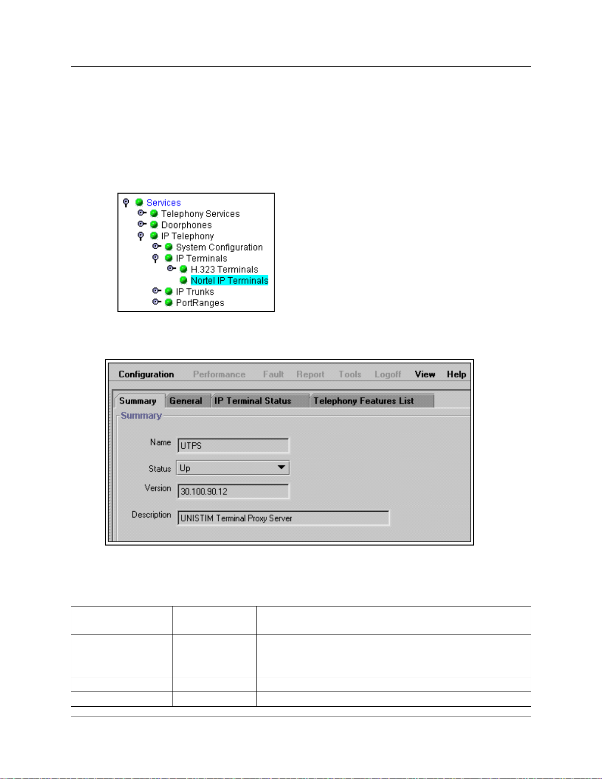
56 Chapter 3 Installing IP telephones
Checking IP server status
You can perform a status check on the Bus iness Communicatio ns Manager serve r that gets used to
register IP terminals. This sc ree n provides information about the serve r and whether the te lephone
properly registe red.
1 In the Unified Manager, open Services, IP Telephony, IP Terminals and click Nortel IP
Terminals.
The IP Terminal summary screen appears.
Figure 6 IP terminal registration server status
2 The following fields provide information about the IP server. Only the stat us field is
configurable.
Table 15 IP terminal Summary fields
Field Value Description
Name UTPS Name of the server.
Status Up
Enabled
Disabled
Version read-only current version of server software
Description read-only description of server
UP: server is operating
Enabled: Server is using DHCP
Disabled: server is not working.
P0609327 02
Page 57
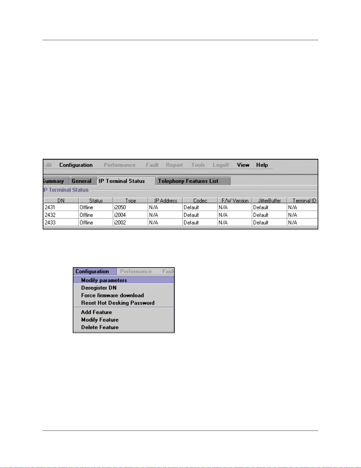
Modifying IP telephone status settings
Settings such as ji tter buffers and codecs for the Nortel IP telephones can be modifie d through the
Unified Manager:
1 In the Unified Manager, open Services, IP Telephony, IP Terminals and click Nortel IP
Terminals. The IP Terminal summary appears.
2 Click the IP Terminal Status tab.
On the IP Terminal status screen, every IP telephone currently connected to the Business
Communications Manager occupi es a row in the IP Terminal Status table, as shown in the
figure below.
Figure 7 IP Terminal status
Chapter 3 Installing IP telephones 57
3 Select the IP Terminal record for which you want to change the prop erties.
4 Open the Configuration menu, or alternate-click anywhere on the terminal listing to open the
Configuration menu and selec t Modify parameters.
The IP Terminal Status dialog box appear s, as shown in the figure below.
IP Telephony Configuration Guide
Page 58

58 Chapter 3 Installing IP telephones
Figure 8 IP Terminal status dialog box
5 You can change the Codec or JitterBuffer setti ngs for the terminal. All other fields are
read-only. The table below describes the two configurable fields on this screen.
Table 16 IP Terminal Status fields
Field Value Description
Codec Default
G.711-aLaw
G.711-uLaw
G.711 with VAD
G.729
G.729 with VAD
G.723
JitterBuffer Auto
Default
None
Small
Medium
Large
Specifying a non-default CODEC for a telephone allows you
to override the general setting. You might, for example, want
to specify a low bandwidth CODEC (g.729) for a telephone
that is on a remote or busy sub-net. Refer to “Choosing a
codec” on page 45.
Note: You can only change the codec on a configured IP
telephone if it is online to the Business Communications
Manager, or if Keep DN Alive is enabled for an offline
telephone.
Increase the jitter buffer size for any telephone that has poor
network connectivity to the Business Communications
Manager.
Refer to “Choosing a Jitter Buffer” on page 46.
Note: You can only change the jitter buffer on a configured IP
telephone if it is online to the Business Communications
Manager, or if Keep DN Alive is enabled for an offline
telephone.
6 Click the Save button.
P0609327 02
Page 59

Working with the features list
You can add and modify the features that display on the IP telephone feature list, which is
accessed through the Servi ces button or by using FEATURE *900. Refer to “Using the Services
button to access featur es” on page 60. T h e Programming Operations Guide provides a complete
list of Business Communicati ons Manager Features and index codes. The Telephony Features
Handbook provides details about usin g the featur es.
Note that the list a ssigns the hot desking fea ture to position 1 (refer to “Resetting the Hot Desking
password” on page 61).
1 In the Unified Manager, open Services, IP Telephony, and click Nortel IP Terminals.
The IP Termina l su mm ary app ear s.
2 Click the Telephony Features list tab.
Figure 9 IP Telephony Features List
Chapter 3 Installing IP telephones 59
3 Select the feature you want to modify and right click, or click the Configuration menu item,
then select the action you want to perfor m.
The Telephony Features li st scre en appears.
IP Telephony Configuration Guide
Page 60

60 Chapter 3 Installing IP telephones
Figure 10 Add/Modify Telephony Features List
4 Enter or change the Feature Name and corresponding Feature Code in the appropriate fields.
5 Click the Save button.
The features list appear s. Notice that the system assigns a Feature Index number, adding the
feature to the bottom of the list.
Refer to the information under “Using the Services button to access features” for a description
about how to use the features list .
Using the Services button to access features
The IP telephone has a limited number of memory buttons that can be configured with lines or
features, however, a soft featur es menu also can be acce sse d by pre ssin g the Services button
.
• Use the up and down directional buttons or the Page +
quickly through the list.
•Press the Select
would. For example: if you selected Call Forward, enter the number you to which you want to
forward the call. Or, if you select speed dial (FEATURE 0), enter the speed dial code for the
number you want the telephone to dial.
This feature a llows you to a ssign your har dware fe ature keys to l ine a nd int ercom appl icat ions, a nd
still access the Bu si n ess Com munication s Manag e r cal l fea tur es with out ne ed in g to reme mb er a
feature code. Although the list is defaulte d to the Service s button, you can assign the display list to
one of the other hard feature keys. The user can also assign it as a memory button, using
FEATURE *3, at a specific te lep h one . Ref er to the Programming Operations Guide for
information about prog ramming IP telephone memory buttons under User Preferences.
display key to activate the feature, the n use the feature as you normally
and Page - display keys to move
Note: If you move the feature to another memory button, the Services button no longer accesses
the menu.
P0609327 02
Page 61

Resetting the Hot Desking password
You can transfer your IP telephony configuration temporarily from one IP telephone to another
using the Hot Desking feature. This feature is described in detail in the Telephony Features
Handbook. You use FEATURE *999 to enter the feature. To perform hot desking, you are
prompted for a password, which is speci fied at the telephone, before you can complete the task.
The Hot Desking password can be reset from the Unified Manager. This allows users who forget
their passwords to re-e nter hot desking and to reset their password.
Note: This proce ss also cancels hot desking for the telephone, if the application is cur rently active.
Refer also to “N otes about Hot Desking” on page 62.
To reset the Hot Desking password field f or a specif ic IP telephone:
1 Click the keys beside Services, IP Telephony and IP Terminals keys.
2 Click Nortel IP Terminals.
3 Click the IP Terminal Status tab.
Chapter 3 Installing IP telephones 61
Figure 11 IP Terminal Status tab list
4 Select the IP telephone record you want to reset.
5 On the top menu, click Configuration, then select Reset Hot Desking Password.
6 A dialog box appears, prompting you to proceed. Click Yes to reset the password.
The password resets to Null. The user can enter hot desking again to enter a new password.
IP Telephony Configuration Guide
Page 62

62 Chapter 3 Installing IP telephones
Notes about Hot Desking
• The Hot Desking feature allows a user to divert calls and signals from one IP telephone to
another. For instance, if a user is temporarily working in another office, they can retain their
telephone number by hot desking the ir usual telephone to the IP telephone in their temporar y
office.
• The headset mode is not transferred by this feature.
• Hot desking can be accessed using FEATURE *999 on the telephone to which the traffic wil l
be diverted. The user can also evoke this feature from the Services key menu, where it is
defaulted as the first item on the list. Both telephones must be on-hook before the feature can
be used or cancelled.
• Hot desking must be allo wed on the origi nating te lephone a nd you need t o specify a pas sword.
These settings are found unde r the ADMIN
invoked through the DIVERT key within the hot desking feature.
• If the originating tel ephone does not have hot desking allowed, the user will receive a
Not allowed prompt, indicating that the telephone is not available for hot desking. This
prompt also occurs if the origina ting telephone is on a call when the diversion command was
issued.
• Once hot desking occurs between two IP telephones, no activity is allowed on the originating
telephone, except to cancel hot desking. The display on the originating telephone indicates
where it has been diverted. On the diverte d telephone, the key displays reflect the displays
from the originating tele phone.
• Call forwar din g to voice mai l con tinu e s as norm al . Vo i ce ma il can be acces s ed fro m the
diverted IP telephone , as if it were the originating telephone.
• When hot desking i s cancelle d, whic h can be per formed from eithe r tele phone, t he displa ys for
each telephone return to normal. Note: You must wait 10 seconds after completi ng a call
before you cancel hot desking.
• Using headsets with hot de sking: If you use the headset fe ature on your IP telephone, and you
want to hot desk your tel ephone to anot her IP telephon e, ens ure that th e targe t telephone also a
headset installed before you enter the hot desking feature.
• If the target telephon e does not have a heads et, the headset feature from the first tele phone
does not transf er duri ng hot desking. Adding a headset to th e target t el ephone afte r hot d esking
is enabled doe s not correct t he situation. To e nable headset func tion in this situation, you nee d
to cancel hot desking, plug a headset into the target telephone, and then re-establish hot
desking.
key within the hot desking feature. Hot desking is
P0609327 02
Page 63

• If the target telephon e has a headset, but the originating telephone does not, once hot desking
is activated the headset on the target telephone will no longer work. To correct this situation,
you need to cancel hot desking, plug a headset into the originating tele phone, then r e-e stablish
hot desking at the target tele phone.
Originating telephone T arget telephone
Chapter 3 Installing IP telephones 63
Head set feature active on
target set after hot desking?
Yes
No
Refer to the Telephony Features Handbook for details about using this feature.
Customizing feature labels
When your IP telephone acquires a DN record, the def ault settings are applied to the telephone,
including assigni ng features to the memory keys on the telephone. These featu res all have
pre-defined labe ls, and the telephone automatically displays the appropriate labels be side the
programmed buttons. If you want to customize these labels to be more appropriate, you can do so
through the Featur e Labels heading on the Unified Manager.
The screens under the Feature Labels heading allow you to define custom labels for 24 featur es.
The system comes with 10 default labels, which are feature and language-spec if i c , de pending to
which region your system was assigned. The default labels are mainly messaging and call
attendant feature s.
However, you can change any other feature label by adding to this list, or by deleting any of the
default settings and inserting new codes and labels.
No
Refer to “Changing features or labels on the memory buttons” for details about changing feature
labels.
IP Telephony Configuration Guide
Page 64

64 Chapter 3 Installing IP telephones
Changing features or labe ls on the memory buttons
Follow these steps to change the features or labels on the memory buttons on your IP telephone:
1 Click the Telephony Services, General, Nortel IP terminals, and Feature labels keys.
2 Click the label set you want to view.
The Labels <label number> screen appears.
Figure 12 Label set defaults
3 If you have an existing list, or you do not want to change any defaults, go to the first empty
Feature fiel d.
4 In the Feature <label number> field, enter the feature c ode f or the f eatu re you wa nt to r elabel.
Example : enter 3 for conference call
5 In the Label <label number> field, enter the new label you want the telephones to display.
Example: The curren t label for feature code 3 is Conference, you could change it to Conf Call.
6 Click anywhere outside the field to save the changes.
The system automaticall y updates any IP telephones that have a button appeara nce for the
feature.
P0609327 02
Page 65

Chapter 3 Installing IP telephones 65
Some features, like Page and System Wide Call Appearances (SWCA), have several variations of
feature invocation tha t you may want to custom ize for the users.
Paging can be F60, F61x, F62, and F63x. System-wide Call Appe arance (SWCA) has 16 codes
(*521 to *536). The followin g table shows exa mples of changi ng labels f or page codes and S WCA
codes:
Table 17 Relabelling examples
Feature code New label Feature code New label
60 Gen Page *521 SW Call 1
610 Pg Every *522 SW Call 2
61 Zone <digit from
1-9>
62 Speak Pg *524 SW Call 4
630 Speak, All
*523 SW Call 3
*525 SW Call 5
Note: Line names are def ined when you configure the li ne, and can be changed through the Lines
menus.
Download f ir mware t o a Nort e l IP telep hone
Firmware is th e software stored in the telephone. When the Business Communications Manager is
upgraded with a new IP telephone firmware loa d, this f irmware load aut omatica lly downloa ds into
the IP telephones when they next connec t to the Business Communications Manager.
You can use the Force firmware download option under the Configuration menu (Nortel IP
Terminals) to force immediate download to a telephone . You would do this in situa tions where
you suspect that a particula r telephone has corrupted firmware.
Forcing a firmware download to an IP telephone
Follow these steps to force a firmware download to a telephone:
1 In the Unified Manager, open Services, IP Telephony, IP Terminals, and click Nortel IP
Terminals. The IP Terminal summary appears.
2 Click the IP Terminal Status tab.
3 Select the listing for the IP telephone you want to upgrade.
4 Open the Configuration menu, or alternate-click anywhere on the listing for the terminal to
display the menu.
5 Select Force Firmware Download.
A message appears that asks you want to confir m that you want to procee d.
6 Click the Yes button.
The firmware download begins.
IP Telephony Configuration Guide
Page 66

66 Chapter 3 Installing IP telephones
The system drops any active call on that te lephone, and downloads a new firmware load into the
selected telephones. The telephones will be unusable until the download is complete and the
telephones have reset .
Note: In order not to saturate the IP network with download packets, the system will only
download up to five IP telephones at any given tim e. Telephones requiring download will show a
Unified Manager status of
(UTPS) will initiate download as resources become available.
Download Pending, and the UNISTIM Terminal Proxy Server
Deregistering DNs for IP telephones
You can deregister selected telephones from the Business Communicati ons Manager, and force
the telephone to go through the registration process again.
Warning: After this feature is activated, all active calls are dropped.
There are two ways to deregister an IP telephone:
•use the Nortel IP Term i nal s Configuration menu (“Deregistering a tele phone using the IP
record” on page 66)
•use the Configuration menu under one of the relevant headings under DN registration
(“Deregistering a telephone usin g a DN registra tion heading” on page 67)
Deregistering a teleph one using the IP record
To deregister a DN for an IP telephone from the IP record:
1 In the Unified Manager, open Services, IP Telephony, IP Terminals, and click Nortel IP
Terminals.
The IP Termina l su mm ary app ear s.
2 Click the IP Terminal Status tab.
3 Select the IP Terminal with the DN you want to deregister.
4 Open the Configuration menu, or alternate-click anywhere on the listing for the terminal to
display the menu, as shown in the next figure.
P0609327 02
Page 67

Chapter 3 Installing IP telephones 67
Figure 13 Deregister DN from Configuration menu
5 Click Deregister DN.
6 Reregister the te lephone , as d escribed in “Configur in g the i2 0XX tele phones to the sys tem” on
page 47.
Warning: After this feature is activated, all active calls are dropped.
Deregi stering a telephone using a DN registration heading
To deregister a DN from a DN registration record:
1 In the Unified Manager, click the keys beside Services, System DNs, DN registration , IP set
DNs reg’d.
2 Click the key beside one of the following:
• Active, if you are deregistering an acti ve IP telephone
• Inactive, if you are deregistering an inactive IP telephone.
3 Select the DN for the IP Terminal you want to deregister.
IP Telephony Configuration Guide
Page 68

68 Chapter 3 Installing IP telephones
4 Click on the Configuration menu, then select Deregister. Refer to the figure below.
• If you run Deregister on an active device, you will be prompted to confirm that you
understand that the device will be terminated. If you click OK, the device is deregistere d
immediately.
• If you run Deregister on an inactive device, there will be no prompts , and the action will
occur immed iat ely.
Figure 14 Deregister DN from Configuration menu
P0609327 02
Page 69

Moving IP telephones
IP telephones retai n their DN when they are moved to a new location on the same subnet. The
following instructions apply to Nortel IP telephones.
Moving IP telephones and retaining the DN
To move an IP telephone without changing the DN:
1 If you want to retain DN-specific features such as Call Forward No answer and Call Forward
on Busy if an IP telephone becomes disconnected, you must activate the Keep DN alive
setting, as described below. Otherwise, go to step 2.
a In the Unified Manager, under the Services, Telephony Services list, click the DN record
for the IP telephone.
b Click the Capabilities heading.
c Beside the Keep DN alive field, choose Y.
Choosing N for this field allows the DN record to becom e inactive if the IP telephone is
disconnected. This produces a
such as Call Forward, are invoked.
Not in Service prompt if any of the special features,
Chapter 3 Installing IP telephones 69
Warning: If the system is rese t wh ile an IP tel ep hone is disconnect ed, the K eep DN alive
feature becomes inactive until the telephone is reconnect ed. This setting must be enabled if
you want to change the codec or jitter buffer for an IP telephone that is offline.
Note: When an IP telephone is disconnected, there is about a 40-second delay before the
system activate s Keep DN ali ve during whic h i ncoming calls will e ither ge t a busy signal or be
rerouted to the Prime set, depending on how your system is programmed. The same type of
delay occurs when the IP telephone is reconnected to the system.
2 Disconnect the power from the IP telephone or 3-port switch.
3 Disconnect the network connection.
4 At the new location, reconnect the networ k cable and the power connection.
5 If the new location is on a different subnet, you will need to make the appropriate changes to
the telephone IP addressing. However, do not change the S1 IP address or the S2 IP address.
Note: If your network is using partial DHCP, reconfiguration is not required at this step.
Moving telephones and ch anging the DN
To move a Nortel IP telephone and change the DN:
1 Deregister the DN using the instructions in “Deregistering DNs for IP telephones” on page 66.
2 Disconnect the network connection and the power connection from the telephone.
3 Reinstall the phone at the new location and reconfigure the telephone. For information about
this, see “Connecting the i200X telephones” on page 47.
IP Telephony Configuration Guide
Page 70

70 Chapter 3 Installing IP telephones
Configur ing a new time zone on a remote telephone
If the IP telephone connects to the system from a different time zone than the Business
Communications Manager, you can reset the telephone so that it displays the correct local time.
1 At the telephone, enter FEATURE *510.
2 Press
3 Press * to toggle between + and - (minus), depending on which side of the time zone the
4 Enter the number of hours difference.
5 Press
Offset time zones: For areas, such as Newfoundland, C anada, where the tim e zone is offset f rom a
full hour, press the # key to add .5 to the number of hours, then press
Note: The telephone is still configured to change when Daylight Savings Time occurs if the host
Business Communications Mana ger is programmed to change. Therefore, if the telephone is in an
area that does not change time, for example , S askatchewan, Canada, you will need to readjus t the
time on your IP telephone at each time change. You will also need to readjust the time if the IP
telephone is in a time zone that changes and the Business Communications Manager is not, for
example, if the telephone is in Alberta, Canada and the Business Communications Manager is
located in the business headqua r ters in Saskatchewan.
CHANGE.
telephone is locate d. As a rule of thumb, west is minus (-); east is plus (+)
OK.
OK.
P0609327 02
Page 71

Chapter 3 Installing IP telephones 71
Nortel Networks i2050 Software Phone
The Nortel Networks i2050 Software Phone allows you to use a computer equipped with a sound
card, microphone , and USB headset t o func tion as an IP te rminal on th e Business Communicati ons
Manager system. The Nortel Networks i2050 Software Phone uses the computer IP network
connection to connect to the Busi ness Communications Manager. The registra tion process is the
same as for the i200X telephones (“Registering the telephone to the system” on page 48).
When you instal l the Nortel Networks i2050 Software Phone, on-screen documentation walks you
through the steps for instal l ing the software. Yo u ca n also refer t o the i2050 Software Phone
Installation Guide .
Refer to the following section for details about configuring the Business Communications
Manager connections for the Nortel Networks i2050 Software Phone:
Configuring the i2050 Software Phone for the local system
1 Click the Start button and then click Settings.
2 Click Contr ol Panel.
3 Double click the i2050 Software Phone icon.
The utility opens to the Communicat ions Server tab, as shown in the figure below.
Figure 15 i2050 Communications server
IP Telephony Configuration Guide
Page 72

72 Chapter 3 Installing IP telephones
4 Enter the Published IP address of the Business Communications Manager in the IP address
field.
5 From the Port menu, select BCM.
6 Select the Server Type ta b. The screen shown in the following figure appears.
Figure 16 i2050 Switch type
7 Click the BCM option.
8 Enable the Select Sound D evi ces tab for the USB headset.
To further configure this device through Unifi ed Manager, see “Modifying IP telephone status
settings” on page 57.
P0609327 02
Page 73

Chapter 4
Installing NetVision telephones
This section describes how to configure the Symbol NetVision handsets to the Business
Communications Manager syst em.
Programming Note: If your system is running DHCP, ensure that you create a static IP list for all
the NetVision telephon es you want to program.
The information in this section includes:
• “NetVis ion co n nect iv ity ”
• “Configuring NetVision recor ds” on page 75
• “Modifying H.323 terminal records” on page 81
NetVis ion connecti v it y
The Business Communications Manager supports access points, NetVision handsets and other
wireless IP devices that use either IEEE 802.11 (1 or 2 M-bits/sec, Frequency Hopping Spre ad
Spectrum) or IEEE 802.11B (11 M-bits/sec, Direct Sequence Spread Spectrum) technology.
NetVision telephone s use an enhanced version of H.323.
73
NetVision and NetVision Data wir eless IP telephones connect to the Business Communicat ions
Manager over a LAN through the Business Communications Manager LAN or WAN card. The
Business Communication Manager sees the se telephones as IP telephones, which means that the
DN records are assigned from the digital range rather than from the Companion or ISDN range of
DNs.
From within the system, the handset s can make and receive calls from any tr unk typ e supported by
the system, which can include voice over IP (VoIP) H.323 trunks, digital and analog tr unks. The
handset DN record determines whic h lines the handset can access.
Note: NetVision handsets cannot use trunks that have been configured with the SIP protoc ol.
The handset can communicate with any other type of telephone supported by the Business
Communications Manager syst em.
Click on the following heading s to view more info rmation about NetVision connectivity.
Access poin ts
Instructions a bout inst al ling an 802.11b a ccess po int ar e provide d wit h the ac cess point equ ipment,
which is sold and installed separately. The acc ess point is set up with a unique ident ifier (ESS ID)
which is entered into the handset either through a configur ation download or manually th rou gh the
dialpad to allow the handset to access the system through that access point.
IP Telephony Configuration Guide
Page 74

74 Chapter 4 Installing NetVision telephones
Keycodes
Before setting up NetVision te lephones, ensure that you have enough IP client keycodes enabled
to register all the NetVision telephones you require. For information about entering keycodes, see
the Keycode Installation Guide. IP clients are dist ribute d on a one- to-one basis with NetVis ion and
IP telephones, so ensure that you take your entire system into consideration.
Handset and call functions
Symbol supplies a hands et use r guide tha t desc ribes the fe atures on the NetVisio n handse t and how
to use them to perform basic functions.
The Business Communications Manager NetVision Feature card explains how to use the handset
to access features on the Busines s Communications Manager syste m and provides some quick tips
for basic call functions.
The Business Communications Manager Telephony Features Handbook provides information
about how to use Business Communications Mana ger call f eatures.
The Business Communications Manager NetVision Phone Administrator Guide provides
instructions for assigning features to the display list, and includes an appendix containing a list of
the features that work with NetVision handsets.
Codecs
You can specify a preferred codec for your H.323 terminals. As well you can set a specific codec
in individual handset records. This allows you to create the preferred call environment for your
NetVision-based communications. The settings you choose depend on the expected network
connection points of the hands ets. If all the handse ts are expecte d to be used within a common and
consistent networ k, you can use the general, default setting. Howe ver, some handsets that connect
through busy systems may need specif ic settings to ensure consistent voice qual ity.
The default codec for NetVisi on handsets is G.729. However, if the NetVision handsets connect
over IP trunks, the codec of the IP trunk takes precedence.
Caution: NetVision handsets experience communications problems if your system has a
NAT between the handset internet connection and the published address of the Business
Communications Manager LAN. For this reason, this configuration is NOT supported.
P0609327 02
Page 75

Chapter 4 Installing NetVision telephones 75
Configuring NetVision records
This section provides the steps for configuring the various reco rds that the NetVision telephone
requires to work on a Business Communications Manager system.
The information under the following headings describe:
• What information you requir e before you configure your handsets (“Gathering system
information before you start”).
• How to set up default codecs for all terminals (“Assigning general settings” on page 76).
• How to determine the current status of H.323 on the system (“Monitoring H.323 service
status” on page 77).
• How to set up an H.323 Terminals record on the Business Communications Manager to allow
the NetVision handset to c onnec t to the sys tem (“Assigning H. 323 Ter minals records ” on pa ge
78).
Gathering system information before you start
Ensure the following is complete, or the inform ation is on hand before you start configuring your
NetVision telephone s:
1.
If the system to which the handsets are registering is running
DHCP, ensure that you enter a static IP list for all the NetVision
handsets you intend to create.
2.
The Business Communications Manager has been set up to
allow IP telephones.
3.
If you are configuring the Business Communications Manager
records before you configure the handset: You know which DNs
you want to assign to the handsets and you have all the line,
restrictions, and telephony information you require to create or
update a DN record for each telephone.
4.
Download the latest version of the NetVision Phone Administrator
http://www.symbol.com/services/downloads/nvfirmware2.html
Download the latest firmware version from the same website.
5.
You have obtained the Symbol NetVision serial cable, which is
used to transfer configuration information between the computer
where the tool is installed and the handset.
6.
You have a list of names that you will use for the handsets. Each
name must be unique to a handset. Both the H.323 Terminals
record and the NVPA record must have exactly the same name.
Refer to “Media gateway
parameters for IP service” on
page 37.
DN records
Purchased from Symbol
/symbol.com>
(part number: 25-20528-01)
Name field
at <http:/
IP Telephony Configuration Guide
Page 76

76 Chapter 4 Installing NetVision telephones
7.
You have identified a PIN for each handset. Password field
8.
You have determined how you want to program codecs. H.323 Terminals Record, and
General record
Assigning general settings
If you want your handse ts to all use the same de fault codec and jitterbuf fer, use the settings on the
General screen.
1 In the Unified Manager, click the keys besid e Services, IP Telephony, and IP Terminals.
2 Click H.323 Terminals.
3 Click the General tab.
Figure 17 Defining Codec and Jitter Buffer for all terminals
4 Use the information in the table below to determine default codec settings.
Table 18 H.323 Terminal list
Field Value Description
Codec G.729
G.711-uLaw
G.711-aLaw
Specifying a non-default CODEC for a telephone allows you
to override the general setting. You might, for example, want
to specify a low bandwidth CODEC like G.729 for a telephone
that connects to a remote or busy sub-net.
P0609327 02
Page 77

Chapter 4 Installing NetVision telephones 77
Monit o ring H.323 service status
The Summary screen under H.323 terminals tells you what connection status is available to H. 323
terminals.
1 In the Unified Manager, click the keys besid e Services, IP Telephony, and IP Terminals.
2 Click H.323 Terminals.
The Summary screen is the visible tab.
Figure 18 Viewing the Summary tab for H.323 terminals
3 The following table describes the fields on the screens.
Table 19 H.323 terminals Summary fields
Field Value Description
Name VoIP gateway This is the type of gateway that the H.323 handsets will be
using. (read-only)
Status Up
Enabled
Disabled
Version <digits> Current version server software. (read-only)
Description H.323 Voice Over
IP Gateway
UP: H.323 handsets can be administered on this system
Enabled: This service is enabled.
Disabled: This service is disabled.
The type of gateway available to H.323 terminals. (read-only)
IP Telephony Configuration Guide
Page 78

78 Chapter 4 Installing NetVision telephones
Assign ing H.323 Terminals records
The H.323 Terminals record (Services, IP Telephony, IP Terminals) identifies the NetVision
handsets within the Business Communications Manager. The Business Communications Manager
uses the information from this file to determine if the handset will be allowed to connect to the
system.
Pre-configuration notes for NetVision handsets
The following are some notes about the process of configuring handsets to the Business
Communications Manager.
• You must have an H.323 record configured be fore you configure the handsets with the Nortel
NVPA.
• Each telephone tha t you configure will use one IP c lient assignment, so ensure that you added
enough keycodes to accommodate both your IP telephones and your NetVision telephones.
•The Name you specify in the H.323 record must match the User Name you specify in the
Nortel NVPA tool, otherwise, the handset will not be allowed to connect to the Business
Communications Manager.
• If you do not specify a DN in the H.323 record, one will automatically be assigned to the
handset. If you specified a DN record , it will a ppear under the Active DNs heading once the
handset connects to the syst em. I f you want to specify a range of DNs, you can use the
Add Users Wizard. This wizard is explained in the Programming Operations Guide.
Caution: If your system uses the Call Center application, there is a potential conflict for
DN assignment if you choose to allow the system to auto ass ign DNs to your handsets. In
this case, it is recommended that you manually configure the NetVision DNs before
allowing them to register to the system.
• DN records for NetVision handsets a re cre ated in the same way as for all other telephones on
the system. The various settings for DN records are described in the Programming Operations
Guide. Choose model IPWls (IP Wireless), when configuring NetVision DN records.
• Once the handset registers with the system, the DN also appears under Telephony services,
System DNs, DN Registration, IP wireless DNs reg’d, Active/Inactive. If you need to
deregister the handset, you can use the Configuration menu under this heading
(“Deregistering a telephone” on page 83).
If you need to chang e the H.323 Terminals record, refer to “Updating the H.323 terminals record”
on page 81 and “Deleting a NetVision telephone from the system” on page 82. If you require
information about changing the DN records, refer to the Programming Operations Guide for
details.
P0609327 02
Page 79

Chapter 4 Installing NetVision telephones 79
Adding a NetVision record in the Unified Manager
Follow these steps to preconfigure an H.323 Terminals record for each hands et you install:
1 In the Unified Manager, click the keys besid e Services, IP Telephony and IP Termi n a l s.
2 Click H.323 Terminals.
3 On the top menu, click Configuration, and choose Add Entry.
The H.323 Terminal List dialog box appears.
Figure 19 H.323 Terminal list dialog box
4 Use the information in the table below to set up your NetVision handset IP system record.
IP Telephony Configuration Guide
Page 80

80 Chapter 4 Installing NetVision telephones
Table 20 H.323 Terminal list
Field Value Description
Name <alphanumeric> This is the name for the handset. This name must have
unique characters for at least the first seven digits.
Note: This is the same name that you will enter in the Nortel NVPA configuration
record for the User Name of the handset. This name must be unique within the
first seven characters for each handset, and can be a maximum of 10 characters.
DN <DN number> or0This is the assigned DN for this handset. If you want the
system to dynamically define a DN, enter 0 (zero).
Note: This field cannot be left blank.
Password <numeric> Enter a unique password. This is what the user must enter on
the handset to connect to the system from the handset.
You must enter at least four digits. This is a mandatory field.
IP Address (read-only) This field populates when the system assigns an IP address
to the handset.
Status (read-only) This field populates when the system registers the handset.
Codec Default
G.729
G.711-uLaw
G.711-aLaw
5 Click the Save button.
Note: Shortly after the H.323 Termi nals record is saved, the system moves the DN you
specified to the Active DNs list. If you have not already done so, configure the DN record for
user requirements. If you are not sure about how to configure DNs, refer to the Programming
Operations Guide for detai ls about the various settings within this record.
Programming note: Ensur e that you choose Model IPWls on the DN record General screen.
6 When the handset is registered, check the handset feature menu, and test the handset to ensure
it is working as you expected. Refer to the NetVision Telephone Feature User Card for
directions about using Business Communications Manager call features on the NetVision
handset.
Specifying a non-default CODEC for a telephone allows you
to override the general setting. You might, for example, want
to specify a low bandwidth CODEC like G.729) for a
telephone that connects to a remote or busy sub-net.
If you choose Default, the telephone will use the codec that is
specified by the VoIP gateway it uses or what is determined
by the gatekeeper, if there is one.
P0609327 02
Page 81

Modifying H.323 terminal records
Once the handset regis ters to the syste m, the H.3 23 terminal r ecord a ppears on t he H.323 Ter minal
List tab page. From that entry, you can modify or delet e the record.
Updating the H.323 terminals record
If you need to change the passwor d for a NetVision telephone , upda te the H.323 terminals record.
Follow these steps to update the H.323 Termina ls record:
1 In the Unified Manager, click the Services, IP Telephony, IP Terminals keys.
2 Click H.323 Terminals.
3 Click the H.323 Terminal List tab.
4 On the H.323 Terminal List screen, highlight the terminal you want to change.
Chapter 4 Installing NetVision telephones 81
5 At the top of the page, click the Configuration menu and selec t Update Entry.
The H.323 Terminal List dialog box appears.
Figure 20 H.323 Terminal list with terminal information
6 Enter a new password.
7 Click the Save button.
IP Telephony Configuration Guide
Page 82

82 Chapter 4 Installing NetVision telephones
Changing a handset Name
The Name is the primary point of recognition for the Business Communications Manager to
identify a handset. If you need to change the name of an assigned handset:
1 Delete the existing r ecord. Re fer to “De leting a NetVisi on tele phone from the syst em” on page
82.
2 Enter a new record with the new name. (“Adding a NetVision record in the Unified Manager”
on page 79)
You can assign the existing DN to the new record.
3 To maintain security, assign a new password.
Changing the DN record of a handset
If you need to change the DN number for a handset, use the Unified Manager (Services,
Telephony Services, General, Change DN). The change will automaticall y be refle cted in the
H.323 Terminals record for the handset.
When you use the Change DN feature, the DN settin g s are trans fe rred to the new DN and the
system features remain active on the new DN.
Warning: Deleting an H.323 Terminals record removes the DN from the Acti ve DNs list.
This means that sys tem features such as Cal l Forwa rd No A nswer also becom e inac t ive.
Deleting a NetVision telephone from the system
If you want to stop a terminal from having acces s to the Busine ss Com munica tions Manager, you
can delete the DN record fo r the termi n al:
1 In the Unified Manager, click the keys besid e Services, IP Telephony and IP Te r m i n a ls.
2 Click H.323 Terminals.
3 Click the H.323 Terminal list tab, then click on the terminal record you want to delete.
4 Click on Configuration and choose Delete Entry .
A message appears that asks you to confirm the del et ion.
5 Click the Yes button to delete the record.
P0609327 02
Page 83

Under the Systems DNs heading, the DN r ecord re turns t o the I nactive DNs li st and di sappear s
from the DN Registration lists.
Deregistering a telephone
If you want to deregister a NetVisi on handset, you use the DN registration record:
1 In the Unified Manager, click the keys besid e Services, System DNs, DN registration, IP
wireless DNs reg’d.
2 Click the key beside one of the following:
• Active, if you are deregistering an acti ve NetVision handset
• Inactive, if you are deregistering an inactive NetVision handset
3 Select the DN for the NetVision handset you want to deregister.
4 Click on the Configuration menu, then select Deregister. Refer to the figure below.
• If you run Deregister on an active device, you will be prompted to confirm that you
understand that the device will be terminated. If you click OK, the device is deregistere d
immediately.
Chapter 4 Installing NetVision telephones 83
• If you run Deregister on an inactive device, there will be no prompts , and the action will
occur immed iat ely.
Figure 21 Deregister DN from Configuration menu
IP Telephony Configuration Guide
Page 84

84 Chapter 4 Installing NetVision telephones
P0609327 02
Page 85

Chapter 5
Configuring local VoIP trunks
This section explains how to configure voi ce over IP (VoIP ) trunks on a Business
Communications Manager syst em for incoming traffic. A VoIP trunk allows you to establish
communications between a Business Communications Manager and a remote system across an IP
network.
The Business Communica tions Manager supports two trunk protocols: H.323 (version 4) and SIP.
Since these pr otocols have different proper ties, they are configured thr ough separate records, even
though many of the same sett ings a re requi red. H.323 tr unks support connectio ns to other Bus iness
Communications Manager s, Meri dian syst ems runnin g IPT so ftware, and t runk-based a ppli cations
such as NetMeeting. SIP trunks curr ently support trunk connections between Busines s
Communications Managers.
• H.323 trunks are programmed under Services, IP Telephony, IP Trunks, H.323 Trunks.
• SIP trunks are programmed under Services, IP Telephony, IP Trunks, SIP Trunk s .
Each trunk is also associate d with a line record, which are found under Services, Telephony
Services, Lines, VoIP lines.
85
Configuring a VoIP trunk requires the following actions:
• “Pre-installation system requirements” on page 86
• “Counting IP trunks” on page 87
• “Configuring media paramete rs” on page 89
• “Setting up the local gateway” on page 91
• “Viewing SIP summary and status” on page 98
• “Incoming calls: Assigning ta rget lines” on page 98
Note: If you are using the Business Communicati ons Manager with a Meridian 1
(M1-IPT) system or a Succession 1000/1000M system for Surviva ble Remote Gateway
(SRG) applications, there are also some interoperabil ity settings to interact with these
systems that need to be taken into consideration. Refer to “IP trunking int eroperability
settings” on page 143.
More VoIP trunk configuration:
• “Setting up VoIP trunks for outgoi ng call s” on page 101 pr ovides infor mation about setting up
your VoIP trunks so your users can make calls to other systems.
• “Optional VoIP trunk configurations” on page 129 provides information about some
applications or features that are not required for all trunks, or which are optional to operation
of the trunks.
Note: VoIP trunks can be used for calls originating from any type of telephone within the
Business Communications Manag er system. Calls coming into the system over VoIP trunks
from other systems can be directed to any type of telephone within the system.
IP Telephony Configuration Guide
Page 86

86 Chapter 5 Configuring local VoIP trunks
You cannot program DISA for voice over IP (VoIP) trunks, therefore, you cannot use COS
passwords to remotely access features over your system. The exception to this would be a
tandemned call, where a call comes into system A over the PSTN, then tandems to system B
over an VoIP trunk. In this case, the remote access package set up for the COS password will
determin e which syst em feat u res are av ai lab le to the caller.
Pre-installation system requirements
Ensure that you have obtained the following information or familiari ze yourself with the
requirements before continuing with VoIP trunk configuration:
Keycodes
Before you can use VoIP, you must obtain and install the necessary keycodes. See the Keycode
Installation Guide for more information about installing the keycodes. Talk to your Business
Communications Manager sales agent if you need to purchase VoIP keycodes.
Each keycode adds a specific number of VoIP trunks. You must reboot your Business
Communications Manager after you enter VoIP keycodes to activate trunking. You then must
identify each trunk as eit her H.323 or SIP trunks. Refer to “Counting IP trunks” on page 87.
If you want to use the MCDN features on the VoIP trunks, you will need an MCDN keycode. If
you have already deployed MCDN for your SL-1 PRI lines, you do not require an additional
keycode.
Note: SIP trunks do not support MCDN.
Published IP add ress
You will require the public IP address to se t up the gateways for VoIP trunks. Refer to “Finding
the published IP address” on page 35 for details.
SIP network data considerations
If you plan to use SIP trunking, ensure that your IP network is set up to accommodate the
restriction s and requirements. Refer to the NAT, Firewall and QoS sections of the Programming
Operations Guide for data programming details for these utilities. To view a general list of
restrictions and requirements, refer to “SIP trunk interoperability issues” on page 188.
H.323 netwo r k app lic at ion s co ns id er at ion s
In order to maintain a level of quality of transmission over VoIP trunks, QoS monitor must be
enabled and configure d. Refer to “Config uring a remote gateway (H.323 trunks) ” on page 103 and
“Quality of Service Monitor ” on page 127.
If your network uses a gatekeeper (H.323 trunks only), there are also spe cific settings that must be
set on the Local Gateway screen to recognize the gatekeeper, and also within the gatekeeper
application, so that VoIP lines are recognized. Refer to “Using a gatekeeper” on page 133. If there
is a gatekeeper on the network, you do not have to configure remote gateway settings.
P0609327 02
Page 87

If you plan to use H.323 tr unk ing and you have a fire wall set up, ensur e that the ports you i ntend to
use have been allowed. Refer to “Incoming calls: Assigning target lines” on page 98 .
Chapter 8, “Typical network applications using MCDN,” on page 147 provides examples of VoIP
trunks used in private networking.
Warning: Ensure that all systems in your network are eit her running BCM 3.5 or newer
software or have the QoS patch installed that allows them to interoperate with BCM 3.5 or
newer software. Systems running BCM software previous to 3.5, which do not have this
patch installed, cannot support VoIP trunks with systems running BCM 3.5 or newer
software. If you need more information, contact your technical support service.
Count i ng IP tru n k s
After you enter the keycodes for your VoIP trunks, you need to specify how many of the trunks
will be used for H.323 trunking and how many for SIP trunking. Once these parameters are set,
you can go to Line programmi ng (Services, Telephony Services) to dete rmine the parameters for
each line, including assigning line pools for each type of trunk so that you can configure the
routing. You must also assign the H.323 or SIP line pools to each telephone that you want to be
able to call out over the lines.
Chapter 5 Configuring local VoIP trunks 87
Since H.323 trunks and SIP trunks use the same pool of available lines (001 to 060), you can use
the IP Trunks Se ttings screen to ke ep track of the total number of enabled trunks and how the y a re
distributed betwe en H.3 23 and SIP trunks.
Determining the IP trunk count
1 Enter the keycodes that you need to enable enough IP lines for your requirements.
2 In Unified Manager, click the keys beside Services, IP Teleph o ny.
3 Click IP Trunks.
The IP Trunks Settings screen appears.
Figure 22 IP Trunks Settings screen
The first two fields are read-only and are determined by the number of IP trunk keycodes you
have installed on your syste m.
IP Telephony Configuration Guide
Page 88

88 Chapter 5 Configuring local VoIP trunks
4 Use the information in the table below to determine the distribution of H.323 and SIP trunks
on your system.
Table 21 Media parameters record
Field Value Description
Maximum Trunks read-only This value is the total number of VoIP trunks you can have
on your system (usually, 60).
Total Trunk Credits read-only This value is determined by the number of VoIP trunk
keycodes you have installed on your system. (4, 8, 12, and
so on)
Number of H.323
Tru nks
Number of SIP Trunks *<digits> Enter the total number of SIP trunks, out of the total number
* The sum of these numbers must not exceed the Total Trunk Credits available.
*<digits> Enter the total number of H.323 trunks, out of the total
number of credits you have available.
of credits you have available.
5 Click anywhere on the navigation tree to exit this screen and activate the settings.
6 Go to Services, Telephony Services, Lines, VoIP lines, Enabled VoIP lines and configure
the lines into line pools. Change the other settings as you would for any other lines . Ref er to
the Lines and Loops chapter in the Programming Operations Guide for details.
7 Go to Services, Syst em DNs, Active Set DNs and select the DNs for the telephones that need
access to these lines, and add the VoIP line pool(s) to the DN record. Refer to the chapter
about configuring DNs in the Programming Operations Guide for details.
8 For any telephones assigned with VoIP line pools that do not have target lines assigned, go to
“Incoming calls: Assi gning target lines” on page 98 and configure targe t lines for these
telephones.
9 To configure incoming traffic, r efer to “Configuring media parameters” on page 89.
To configure outgoing traffic, refer to Chapter 6, “Setting up VoIP trunks for outgoing calls,”
on page 101.
P0609327 02
Page 89

Configuring media parameters
You can use the screen described in this section to determine the order the VoIP trunk will select
codecs, the silence suppression settings, and the jitter buffers.
1 In Unified Manager, click the Services, IP Telephony, IP Trunks keys.
2 Click H.323 Trunks or SIP Trunks, depending on the type of trunk you want to configure.
3 Click the Media Para m et ers tab.
The Media Parameters dialog appears.
Figure 23 H.323 Media Parameters dialog box
Chapter 5 Configuring local VoIP trunks 89
Figure 24 SIP Media Parameters dialog box
IP Telephony Configuration Guide
Page 90

90 Chapter 5 Configuring local VoIP trunks
4 Use the information in the table below to set up the media paramet ers for your system.
Table 22 Media parameters record
Field Value Description
1st Preferred Codec
2nd Preferred Codec
3rd Preferred Codec
4th Preferred Codec
None
G.711-uLaw
G.711-aLaw
G.729
G.723
G.729 + VAD
G.723 + VAD
Select the Codecs in the order in which you want the
system to attempt to use them.
Performance note: Codecs on all networked Business
Communications Managers must be consistent to ensure
that interacting features such as Transfer and Conference
work correctly.
Systems running BCM 3.5 or newer software allow codec
negotiation and renegotiation to accommodate
inconsistencies in Codec settings over VoIP trunks.
Refer to “Codecs” on page 27.
Silence Compression Disabled
Enabled
The silence compression identifies periods of silence in a
conversation, and stops sending IP speech packets during
those periods. In a typical telephone conversation, most of
the conversation is half-duplex, meaning that one person is
speaking while the other is listening.
If silence compression is enabled, no voice packets are sent
from the listener end. This greatly reduces bandwidth
requirements.
G.723.1 and G.729 support silence compression.
G.711 does not support silence compression.
Performance note: Silence Compression on all networked
Business Communications Managers and IPT systems
(VAD setting on IPT systems) must be consistent to ensure
that interacting features such as Transfer and Conference
work correctly. As well, the Payload size on the IPT must be
set to 30ms.
P0609327 02
Page 91

Table 22 Media parameters record (Continued)
Field Value Description
Jitter Buffer - Voice Auto
None
Small
Medium
Large
Select the size of jitter buffer you want to allow for your
system.
Refer to “Jitter Buffer” on page 28.
Chapter 5 Configuring local VoIP trunks 91
T.38 Fax Support Enabled
Disabled
G.729 Payload Size
(ms)
G.723 Payload Size
(ms)
G.711 Payload Size
(ms)
10, 20, 30, 40, 50,
60
Default: 30
30
10, 20, 30, 40, 50,
60
Default:30
Note: This field appears on H.323 screens only, as SIP
trunks do not support this feature.
Enabled: The system supports T.38 fax over IP.
Disabled: The system does not support T.38 fax over IP
CAUTION: Operations note: Fax tones that broadcast
through a telephone speaker will disrupt calls at other
telephones using VoIP trunks in the vicinity of the fax
machine. Here are some suggestions to minimize the
possibility of your VoIP calls being dropped because of fax
tone interference:
• Locate fax machine away from other telephones.
• Turn the speaker volume on the fax machine to the
lowest level, or off, if that option is available.
Set the maximum required payload size, per codec, for the
VoIP calls sent over H.323 trunks.
Note: Payload size can also be set for Nortel IP telephones.
Refer to “Setting IP terminal general settings” on page 43.
Setting up t he loc a l gateway
The call signaling method used by the loca l gateway defines how the Business Communications
Manager prefers call signaling information to be directed thr ough VoIP trunks. Call signaling
establishes and disconnects a call. You set this information in the local gateway screens.
(“Modifying local gateway settings for H.323 and SIP trunks”)
If the net work has a gatekee per (H.323 trunks, only), The Business Communications Manager can
request a method for call signaling, but whether this request is grant ed depends on the
configuration of the gateke eper. Ult imately, the gatekee per decide s which call signaling method to
use. Refer to “Using a gatekeeper” on page 133.
IP Telephony Configuration Guide
Page 92

92 Chapter 5 Configuring local VoIP trunks
SIP trunks communicate between Busi ness Communications Managers. The addressing f or the
remote destination is described in “Setting up SIP trunk subdomain names” on page 97.
Modifying local gateway settings for H.323 and SIP trunks
To modify the settings for your local ga teway:
1 In the Unified Manager, click the keys besid e Services, IP Telephony, IP Trunking.
2 Click H.323 Trunks or SIP Trunks, de pending on what type of VoIP trunk you are
configuring.
The Local Gateway IP Interface screen for that type of trunk appears if you selected H.323
trunks. If you selected SIP trunks, click on the Local Gateway IP Interface tab.
Figure 25 Local gateway IP interface, H.323 Trunks
Figure 26 Local gateway IP interface, SIP trunks
P0609327 02
Page 93

Chapter 5 Configuring local VoIP trunks 93
3 Use the information in the table below to set up the Local Gateway IP interface record.
Table 23 Local Gateway IP interface fields
Field Value Description
Fields that appear for both types of t runks
Fallback to
Circuit-Switched
Enabled-All
Enabled-TDM-only
Disabled
Your choice determines how the system will handle
calls if the IP network cannot be used.
• Enabled-All: All calls will be rerouted over
specified TDM trunks lines.
• Enabled-TDM-only: All voice calls will be rerouted
over specified TDM trunks lines.
• Disabled: Calls will not be rerouted.
Note: Enabled-TDM-only enables fallback for calls originating on digital
telephones. This is useful if your IP telephones are connected remotely, on the
public side of the Business Communications Manager network, because PSTN
fallback is unlikely to result in better quality of service in that scenario.
Fields that appear only for H.323 trunks
Configuration note: Refer to “Using Radvision ECS 3.2 GK as the gatekeeper” on page 134 and
“Using CSE 1000 as a gatekeeper” on page 136 for specific information about
configuring the gatekeeper for H.323 trunks.
Network note: If your private network contains a Meridian 1-IPT, you cannot use
Radvision for a gatekeeper.
*Call Signaling Direct
GateKeeperRouted
GateKeeperResolved
GatekeeperRoutesNoRAS
• Direct: call signaling information is passed directly
between endpoints. The remote gateway table in
the Unified Manager defines a destination code
(digits) for each remote system to direct the calls
for that system to route. In each system, the Nortel
IP Terminals and H.323 Terminals records map IP
addresses to specific telephones.
• GatekeeperResolved: all call signaling occurs
directly between H.323 endpoints. This means that
the gatekeeper resolves the phone numbers into
IP addresses, but the gatekeeper is not involved in
call signaling.
• GatekeeperRouted: uses a gatekeeper for call
setup and control. In this method, call signaling is
directed through the gatekeeper.
• GatekeeperRoutedNoRAS: Use this setting for a
NetCentrex gatekeeper. With this setting, the
system routes all calls through the gatekeeper but
does not use any of the gatekeeper Registration
and Admission Services (RAS).
IP Telephony Configuration Guide
Page 94

94 Chapter 5 Configuring local VoIP trunks
Table 23 Local Gateway IP interface fields (Continued)
Field Value Description
*Gatekeeper IP <ip address> If GateKeeperRouted, GateKeeperResolved or
GateKeeperRoutedNoRAS are selected under Call
Signaling, type the IP address of the machine that is
running the gatekeeper.
Backup
gatekeeper(s)
<IP address>,
<IP address>
NetCentrex gatekeeper does not support RAS,
therefore, any backup gatekeepers must be entered in
this field.
Note: Gatekeepers that use RAS can provide a list of
backup gatekeepers for the end point to use in the
event of the primary gatekeeper failure.
*Alias Names If GateKeeperRouted, GateKeeperResolved, or GatekeeperRoutedNoRAS are
selected under Call Signaling, type one or more alias names for the gateway.
One or more alias names may be configured for a Business Communications
Manager.
Alias names are comma delimited, and may be one of the following types:
• E.164 — numeric identifier containing a digit in the range 0-9. Identified by the
keyword TEL: Example: the Business Communications Manager is assigned
an E.164 and an H323 Identifier: Alias Names: TEL:76,
NAME:bcm10.nortel.com
• NPI-TON — also referred to as a PartyNumber alias. Similar to E164 except
that the keyword indicates the NPI (numbering plan identification), as well as
the TON (type of number). Identified by one of the following keywords: PUB
(Public Unknown Number); PRI (Private Unknown Number); UDP (Private Level
1 Regional Number (UDP)); CDP (Private Local Number (CDP)). Refer to
“Notes about NPI-TON aliases for H.323 trunks” on page 96.
• H323Identifier — alphanumeric strings representing names, e-mail addresses,
etc. Identified by the keyword NAME:
Example: The Business Communications Manager is assigned a public dialed number
prefix of 76, a private CDP number of 45, and an H323 Identifier alias:
Alias
Names: PUB:76, CDP:45, NAME:bcm10.nortel.com
• H.225 (Q.931) CallingPartyNumber (NetCentrex gatekeeper) — The
NetCentrex gatekeeper uses the H.225(Q.931) CallingPartyNumber to resolve
the call originator for billing purposes. This number must then contain a unique
prefix, or location code that is unique across all endpoints that are using the
NetCentrex gatekeeper. Identified by the keyword src:. Example for private
networks: CDP alias = src:<DN>; UDP alias = src:<LOC><DN>. Example for
public network: src:<public OLI>
Note: E164 or NPI-TON alias types are commonly used since they fit into dialing
plans. A Business Communications Manager alias list should not mix these types.
Also, the type of alias used should be consistent with the dialing plan
configuration. Use the same alias naming method on all Business
Communications Managers within a network.
**Registration TTL Default: 60 seconds This TimeToLive parameter specifies the intervals
when the VoIP gateway sends KeepAlive signals to
the gatekeeper. The gatekeeper can override this
timer and send its own TimeToLive period.
P0609327 02
Page 95

Chapter 5 Configuring local VoIP trunks 95
Table 23 Local Gateway IP interface fields (Continued)
Field Value Description
**Gateway Protocol None
SL1
CSE
Both these protocols require a keycode.
SL1: use this protocol only for BCM 2.5 systems
CSE: Use this protocol for BCM 3.0 and newer
systems. This protocol supports Meridian 1 IPT.
Otherwise, use None.
H245 Tunneling Disabled/Enabled Default: Disabled.
If Enabled, the VoIP Gateway tunnels H.245
messages within H.225. The VoIP Gateway service
must be restarted for a change to take effect.
Call Signaling Port 0-65535 Default: 1720
This field allows you to set non-standard call signaling
port for VoIP applications that require special ports.
0 = The first available port is used.
Ensure that you do not select a port that has been
assigned elsewhere in the Business Communications
Manager.
RAS Port 0-65535 Default: 0
This field allows you to set a non-standard
Registration and Admission (RAS) port for VoIP
applications that require special ports.
0 = The first available port is used.
Ensure that you do not select a port that has been
assigned elsewhere in the Business Communications
Manager.
* These fields are mandatory when you use Radvision ECS 2.1.0.1.
** These fields are optional when you use Radvision ECS 2.1.0.1.
Fields that appear only for SIP trunks
SIP Domain <name>.com Enter an identifying domain name for your SIP trunks.
Transport UDP (read-only) This setting refers to the way the Business
Communications Manager internally processes the
trunk packets.
Do not confuse this setting wi t h t he U DP dialing
rule.
IP Telephony Configuration Guide
Page 96

96 Chapter 5 Configuring local VoIP trunks
Notes about NPI-TON aliases for H.323 trunks
NPI-TON aliases st ore dialed number prefixe s as well as information about the type of number. A
dialed number can be qualified according to its TON (type of Number), as well as its NPI
(numbering plan identi fication). Nortel Networks recommends this format over the E.164 format,
for encoding dialed numbers and aliases registered with a gatekeeper .
When using a gatekeeper, and attempting to place an outgoing VoIP trunk call, ensure that the
route and dialing plan configur ation matches the NPI-TON aliases registered, by the destination,
with the gatekeeper. These requirements are summarized in the following table:
Table 24 Route and Dialing Plan configurations for NPI-TON
Route (DN type) Dialing Plan used by calling gateway Alias configured for calling gateway
Public Public PUB:<dialedDigitsPrefix>
Private Private (Type = None) PRI:<dialedDigitsPrefix>
Private (Type = CDP) CDP:<dialedDigitsPrefix>
Private (Type = UDP) UDP:<dialedDigitsPrefix>
P0609327 02
Page 97

Chapter 5 Configuring local VoIP trunks 97
Setting up SIP trunk subdomain names
You can specify the sub-domain names assoc iated with specific system diali ng protocols for SIP
call direction.
Domain names are used by S IP programming to determine the type of call being sent over the SIP
trunk and where it needs to be routed. Refer also to “Configuring remote endpoints (SIP trunks)”
on page 106.
1 In the Unified Manager, click the keys besid e Services, IP Telephony, and IP Trunking.
2 Click SIP Trunks.
3 Click on the Dialing Su b-Domain tab. Refer to the figure below.
Figure 27 SIP Dialing Sub-Domain settings
4 If you change any of the default settings, ensure that you notify the system administrators for
any systems with SIP trunks pointing to your system.
5 When you are finished, click anywhere on the navigation tree to exit and to commit the
changes.
IP Telephony Configuration Guide
Page 98

98 Chapter 5 Configuring local VoIP trunks
Viewing SIP summary and status
SIP trunk programming provides a summar y page that provides general informati on about the
trunks on the system. As well, it indicates the current status of the trunks.
1 In Unified Manager, click the Services, IP Telephony, IP Trunks keys.
2 Click SIP Trunks.
The Summar y dia l og app ea rs .
Figure 28 SIP Summary dialog box
Incoming calls: Assigning target lines
To receive an in coming call di rectly t o the telephone fr om a VoIP network, you nee d to ensure that
the telephone is mapped to a target line.
How to use target lines
A target line routes incoming calls to specific telephone s (DNs) depending on the incoming digits.
This process is independe nt of the trunk over which the call comes in.
• You can assign the target line to a number of telepho nes, if you want the c all to be answerable
to a call group, for instance.
• If System-Wide Call Appearanc e (SWCA) keys are conf igured on memory buttons on the
telephones, the incoming lin e acts the same way as any other incoming cal l, which depend s on
how SWCA has been set up to behave. Refer to the Programming Operations Guide and the
Telephony Feature Handbook for more information about setting up SWCA keys.
• You can assign the target line number to a Hunt Group DN if you want the call to appear on a
group of telephones set up as a hunt group. Refer to the Programming Operations Guide for
more information about setting up Hunt groups.
P0609327 02
Page 99

Chapter 5 Configuring local VoIP trunks 99
Configuring ta rget line s
There are two places where target lines need to be configured:
• The target line is assigned to a telephone, or Hunt group, by assigning a free target line
(241 to 492) to the telephone DN record or Hunt group.
• The incoming digits (e.g. 3321) are assigned to the target line (the same one you assigned to
the telephone) by setti ng the Received Number under that target line to the incoming digits.
If your syste m does not have target lines already assigned, use this procedure to assign target lines
to individual telephones.
Note: You can also use the Add Users wizard if you need to create target lines for a range of
telephones. Refer to the Progr amming Operations Guide for detailed infor mation about using the
wizard.
1 In Unified Manager, open Services, Telephony Services, System DNs.
2 Under the Acti ve Set DNs, Active Compan ion DNs or All ISDN/DECT DNs (or under the
Inactive DNs, if you are preconfiguring DN records) choose the DN record of the telephone
where you want the line to be directed.
3 Choose Line Access, Line assignment and click the Add button.
4 In the Line field, enter the number of an available target line (241-492).
5 Click the Save button.
6 Click the line number you jus t c reated a nd ensur e that you ha ve the line set t o Ring Only if the
telephone has no l ine buttons set for the line, or Appearance and Ring, if you are adding this
to a DN that has line keys or which will be using SWCA keys.
7 Go to Services, Telephony Services, Lines, Target Line <Target line number from step 4>.
8 Click the Trunk/line data key.
9 Click Received number.
10 In the Public number fi eld, enter th e DN.
The telephone assigned to that DN can now receive all calls with that DN number that come into
the Business Communication s Manager to which the telephone is connected. For a detaile d
explanation about target lines, see the Programming Operations Guide.
IP Telephony Configuration Guide
Page 100

100 Chapter 5 Configuring local VoIP trunks
P0609327 02
 Loading...