

Page 1

How to configure an AvayaTM IP600 Server with Cisco
Gatekeeper - Issue 1.0
Abstract
These Application Notes describe the configurations that enable the Avaya IP600 Server to
successfully interoperate with Cisco’s Gatekeeper. These notes describe both an Avaya
Gatekeeper to Cisco Gatekeeper peer configuration, as well as a Multiple Gatekeeper
Configuration between an Avaya Gatekeeper and multiple Cisco Gatekeepers.
SVS; Reviewed:
WCH/MI 6/20/02
Solution & Interoperability Test Lab Application Notes
© 2002 Avaya Inc. All Rights Reserved.
1 of 20
Gatekeeper-ext.doc
Page 2
1. Introduction
One of the functions of a Gatekeeper is to perform E.164 to IP address resolution based on a dial
plan. All remote calls within a Zone are sent to its Gatekeeper, where it is sent either to a
gateway or to another remote gatekeeper zone. These Application Notes describe how to
configure an Avaya™ IP600 Server to interoperate with Cisco’s Gatekeepers and Gateways.
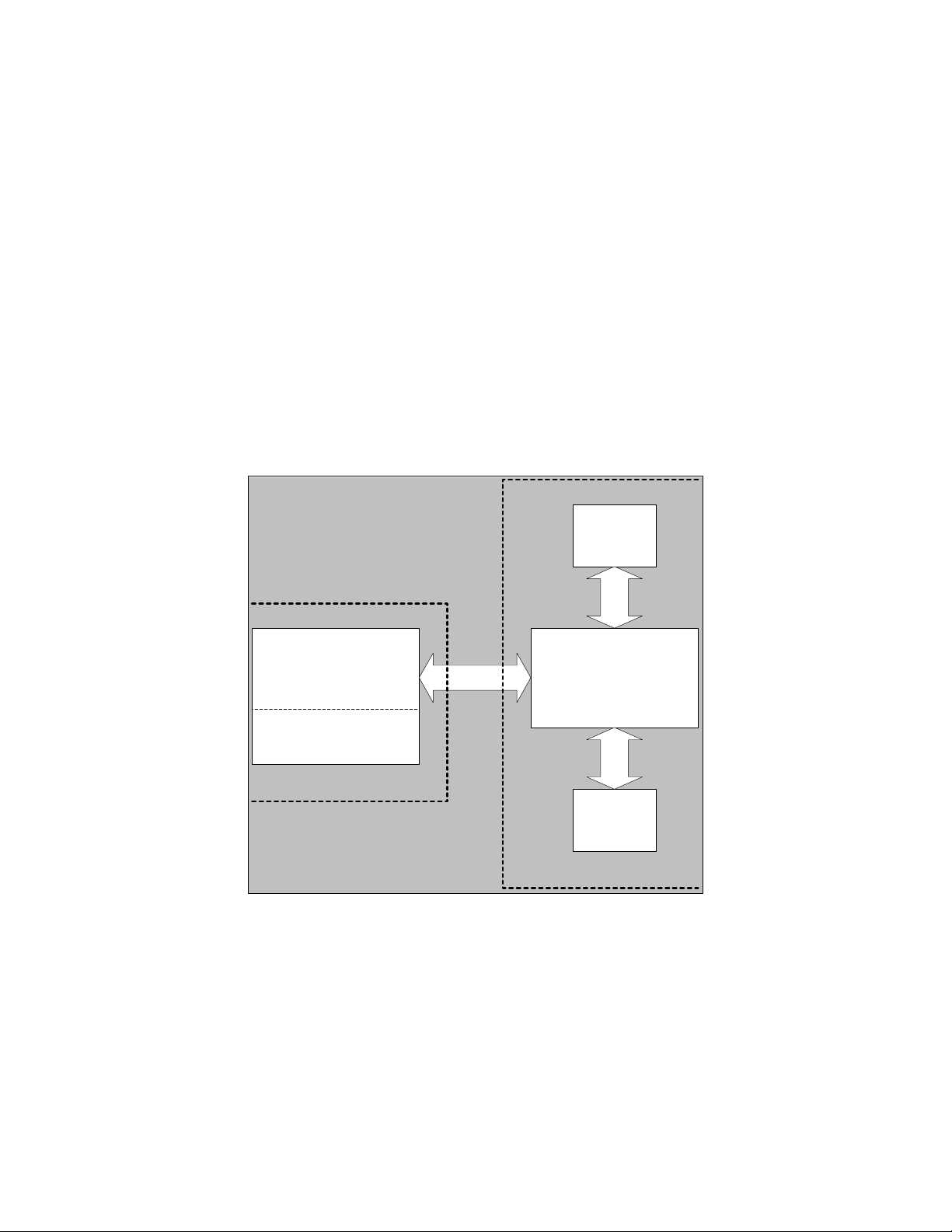
2. Background
In the block diagram (Figure 1) below, the Avaya™ IP600 Server is represented as a Gatekeeper
and Gateway within one box. This is because in H.323 terms, the Avaya IP600 Server is a
Gatekeeper with an embedded or fixed Gateway. Avaya’s IP600 Gatekeeper provides address
translation and control access. Avaya’s embedded Gateway performs the media conversions.
Once an endpoint registers with the Gatekeepers (via RAS), call signaling messages between the
endpoint are routed through Avaya’s Gatekeeper. This method of call signaling is called
Gatekeeper Routed Call Signaling and is the method used by Avaya.
Cisco4604
Gateway A
Avaya IP600
Gatekeeper
Gateway
Zone 1
Cisco 3660
Gatekeeper
Cisco 1751
Gateway B
Zone 2
Figure 1: Block Diagram of IP600 Server and Cisco Gatekeeper
The configuration in Figure 2 is based on the block diagram depicted in Figure 1. In this
configuration, Avaya and Cisco are considered to be in peer gatekeeper zones; that is, the Avaya
Gatekeeper zone manages extensions 77XX, while Cisco Gatekeeper zone manages extensions
62XX and 66XX. When an extension in Zone 1 calls an endpoint in Zone 2, Zone 2 is
considered a remote zone to Zone 1. Likewise in the other direction, when an endpoint in Zone 2
calls an extension in Zone 1, Zone 1 is considered to be a remote zone to Zone 2.
SVS; Reviewed:
WCH/MI 6/20/02
Solution & Interoperability Test Lab Application Notes
© 2002 Avaya Inc. All Rights Reserved.
2 of 20
Gatekeeper-ext.doc
Page 3
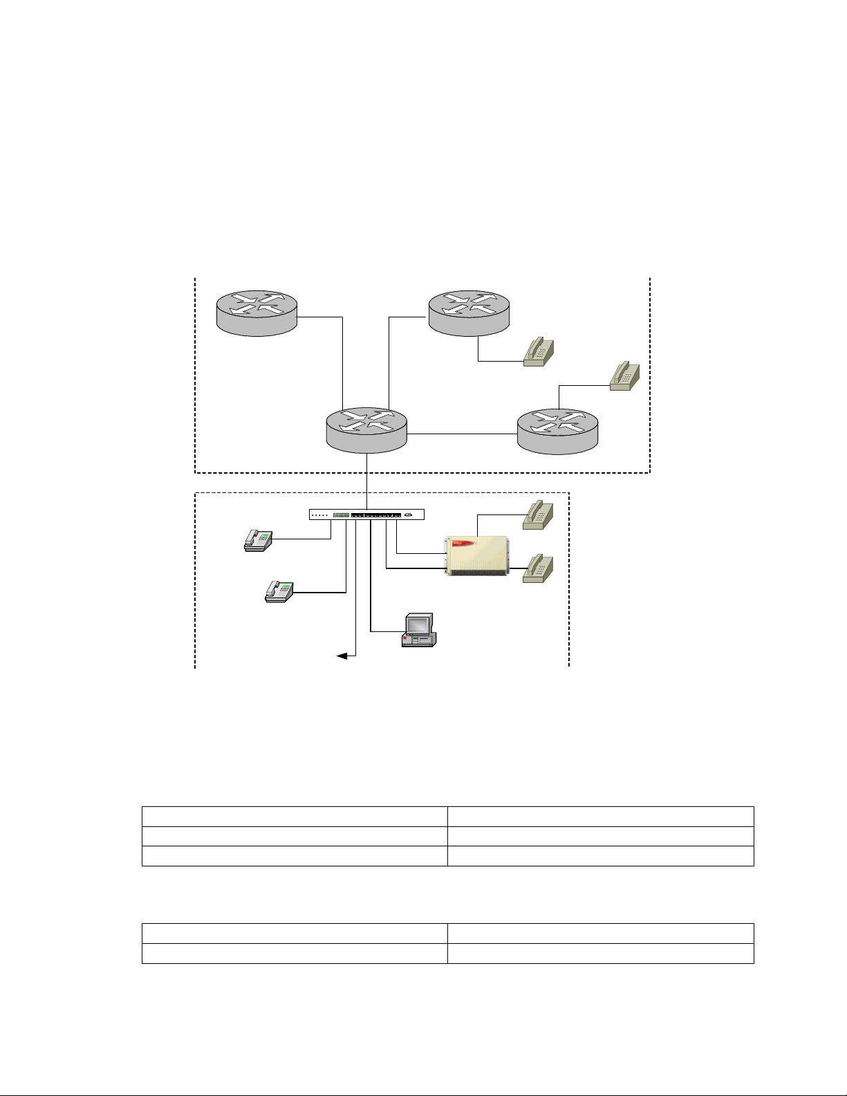
All communications of E.164 traffic must first deal with the Gatekeeper because it is configured
to send or direct E.164 numbers to an appropriate IP endpoint. In Figure 2 for example, when a
phone on Gateway A (Catalyst 4000 Gateway) calls a phone on Gateway B (Cisco 1751), the
E.164 number being called from A is presented to the Cisco’s Gatekeeper. The Gatekeeper finds
the called number and its associated end-point IP address within its configuration. A direct
channel is set up between gateway A and gateway B, where the called number is directed.
Gateway B’s dial-peers steers the call to the port where the actual phone is located.
Cisco 3660
Catalyst 4000 - 4604-GWY
Gatekeeper
Zone 2
Cajun P333T
Avaya IP Phone
X 7702
Avaya IP Phone
X 7712
. 2
10.30.1.0
HS1HS2 OK1OK2 PS
To
DHCP Server
TFTP Server
.1
Cisco 4224
10.9.1.5
123456789101112
COLACTSTA-
. 2
Gateway A
10.50.1.0
.1
10.20.1.0
.1
CONSOLE
CLAN
10.9.1.4
10.9.1.3
Prowler
Avaya IP SoftPhone
X 7716
Avaya
IP 600
Zone 1
. 2
FXS
X 6200
Gateway B
Cisco 1751
DCP
X 7704
DCP
X 7705
FXS
X 6600
Figure 2: IP600 Server and Cisco Gatekeeper
3. Equipment and Software Validated
1. Avaya
Avaya Equipment Version
Avaya™ IP600 Server Version R010c.01.0.032.3
Avaya™ IP Telephone Version 1.51
2. Cisco (IOS)
Cisco Router Version of IOS
Cisco 3660 IOS 12.1.5T10
SVS; Reviewed:
WCH/MI 6/20/02
Solution & Interoperability Test Lab Application Notes
© 2002 Avaya Inc. All Rights Reserved.
3 of 20
Gatekeeper-ext.doc
Page 4

Cisco 1750 IOS 12.2.4T1
Cisco 4224 IOS 12.1.5-YE4
Catalyst 4000 with WS-X4604-GWY IOS 12.2.6a
4. Avaya™ IP600 Configuration
The following screen shots show the pertinent aspects of the Avaya IP600 Server configuration.
The more important aspects are highlighted.
4.1. Outbound Signaling
The administration of the Cisco Gatekeeper as a remote peer requires the addition of a Signaling
/ Trunk Group that points at the Cisco Gatekeeper IP Address as the Far-End (10.30.1.2). In
addition, the appropriate routing (UDP, AAR/ARS, Routing Pattern, etc.) procedures to access
this Signaling / Trunk Group combination are required.
4.1.1. Signaling Group
Permitting the Avaya IP600 server to be administered as a Gatekeeper requires an IP Trunk, and
an H.323 Signaling Group set up as follows. The Signaling Group’s “LRQ Required” is set to
“y”, the Near-End IP address is set to the IP node name of the CLAN (see Node Names-IP) at
port 1719, and the Far-End node name is set to the IP node name of the Cisco Gatekeeper at port
1719. This Signaling Group along with its Trunk Group handles all outbound traffic from Zone
1 to Zone 2.
This Signaling and Trunk Group handle all outbound traffic from Zone 1 to Zone 2. In
addition, the Signaling group points at the Cisco Gatekeeper utilizing port 1719 and “LRQ
Required” must be set to “y”. Note: Cisco uses Port 1719 by default. Also, note that Direct IPIP Audio Connections and IP Audio Hairpinning are set to “n”.
SIGNALING GROUP
Group Number: 6 Group Type: h.323
Remote Office? n Max number of NCA TSC: 0
Max number of CA TSC: 0
Trunk Group for NCA TSC:
Trunk Group for Channel Selection: 6
Supplementary Service Protocol: a Network Call Transfer? n
Near-end Node Name: clan-IP600-gk Far-end Node Name: Gatekeeper
Near-end Listen Port: 1719 Far-end Listen Port: 1719
Far-end Network Region:
LRQ Required? y Calls Share IP Signaling Connection? n
RRQ Required? n
Bypass If IP Threshold Exceeded? n
Direct IP-IP Audio Connections? n
IP Audio Hairpinning? n
Interworking Message: PROGress
SVS; Reviewed:
WCH/MI 6/20/02
Solution & Interoperability Test Lab Application Notes
© 2002 Avaya Inc. All Rights Reserved.
4 of 20
Gatekeeper-ext.doc
Page 5
4.1.2. Trunk Group
In this example, Trunk Group 6 is associated with Signaling Group 6, and includes trunk
member assignment.
TRUNK GROUP
Group Number: 6 Group Type: isdn CDR Reports: y
Group Name: Alternate IP600 Test Networ COR: 1 TN: 1 TAC: 106
Direction: two-way Outgoing Display? y Carrier Medium: IP
Dial Access? n Busy Threshold: 99 Night Service:
Queue Length: 0
Service Type: tie Auth Code? n TestCall ITC: rest
Far End Test Line No:
TestCall BCC: 4
TRUNK PARAMETERS
Codeset to Send Display: 6 Codeset to Send National IEs: 6
Max Message Size to Send: 260 Charge Advice: none
Supplementary Service Protocol: a Digit Handling (in/out):enbloc/enbloc
Trunk Hunt: cyclical QSIG Value-Added? n
Digital Loss Group: 13
Calling Number - Delete: Insert: Numbering Format:
Bit Rate: 1200 Synchronization: async Duplex: full
Disconnect Supervision - In? y Out? n
Answer Supervision Timeout: 0
Trunk Members
Trunk member port values are initially created by assigning the term “ip” in the Port column.
The system will then assign the T000xx value to the port as shown below.
TRUNK GROUP
Administered Members (min/max): 1/7
GROUP MEMBER ASSIGNMENTS Total Administered Members: 7
Port Code Sfx Name Night Sig Grp
1: T00049 6
2: T00050 6
3: T00051 6
4: T00052 6
5: T00053 6
6: T00054 6
7: T00055 6
SVS; Reviewed:
WCH/MI 6/20/02
Solution & Interoperability Test Lab Application Notes
© 2002 Avaya Inc. All Rights Reserved.
5 of 20
Gatekeeper-ext.doc
Page 6

4.2. Inbound Signaling
All inbound traffic from Zone 2 to Zone 1 requires an additional Trunk and Signaling Group.
In this case, the Signaling Group’s Near-End IP address is set to the IP address of the CLAN at
port 1720, and the Far-End is unspecified.
The unspecified far-end signaling group is used for all incoming calls from Zone 2 to Zone 1.
The Avaya IP600 Server listens on Port 1720 to handle H.225 /Q.931 traffic.
4.2.1. Unspecified Signaling Group
The “Far-end Node Name” field is left blank, and it is necessary that “Direct IP-IP Audio
Connections” and “IP Audio Hairpinning” be set to “n” on this screen.
SIGNALING GROUP
Group Number: 10 Group Type: h.323
Remote Office? n Max number of NCA TSC: 0
Max number of CA TSC: 0
Trunk Group for NCA TSC:
Trunk Group for Channel Selection: 10
Supplementary Service Protocol: a Network Call Transfer? n
Near-end Node Name: clan-IP600-gk Far-end Node Name:
Near-end Listen Port: 1720 Far-end Listen Port:
Far-end Network Region:
LRQ Required? n Calls Share IP Signaling Connection? n
RRQ Required? n
Bypass If IP Threshold Exceeded? n
Direct IP-IP Audio Connections? n
IP Audio Hairpinning? n
Interworking Message: PROGress
SVS; Reviewed:
WCH/MI 6/20/02
Solution & Interoperability Test Lab Application Notes
© 2002 Avaya Inc. All Rights Reserved.
6 of 20
Gatekeeper-ext.doc
Page 7

4.2.2. Trunk Group
This Trunk Group is used in conjunction with the unspecified Signaling Group.
TRUNK GROUP
Group Number: 10 Group Type: isdn CDR Reports: y
Group Name: Alternate IP600 Test Networ COR: 1 TN: 1 TAC: 110
Direction: two-way Outgoing Display? y Carrier Medium: IP
Dial Access? n Busy Threshold: 99 Night Service:
Queue Length: 0
Service Type: tie Auth Code? n TestCall ITC: rest
Far End Test Line No:
TestCall BCC: 4
TRUNK PARAMETERS
Codeset to Send Display: 6 Codeset to Send National IEs: 6
Max Message Size to Send: 260 Charge Advice: none
Supplementary Service Protocol: a Digit Handling (in/out):enbloc/enbloc
Trunk Hunt: cyclical QSIG Value-Added? n
Digital Loss Group: 13
Calling Number - Delete: Insert: Numbering Format:
Bit Rate: 1200 Synchronization: async Duplex: full
Disconnect Supervision - In? y Out? n
Answer Supervision Timeout: 0
Trunk Members
Trunk member port values are initially created by assigning the term “ip” in the Port column.
The system will then assign the T000xx value to the port as shown below.
TRUNK GROUP
Administered Members (min/max): 1/6
GROUP MEMBER ASSIGNMENTS Total Administered Members: 6
Port Code Sfx Name Night Sig Grp
1: T00043 10
2: T00044 10
3: T00045 10
4: T00046 10
5: T00047 10
6: T00048 10
4.2.3. Node Names-IP
The Node Names-IP form configures CLANs, Prowlers, Gatekeepers and their associated IP
addresses. Display or edit the node name by entering: change node-names ip
IP NODE NAMES
Name IP Address Name IP Address
clan-IP600-gk 10 .9 .1 .4 . . .
GateKeeper 10 .30 .1 .2 . . .
default 0 .0 .0 .0 . . .
prowler-600Big 10 .9 .1 .3 . . .
SVS; Reviewed:
WCH/MI 6/20/02
Solution & Interoperability Test Lab Application Notes
© 2002 Avaya Inc. All Rights Reserved.
7 of 20
Gatekeeper-ext.doc
Page 8

4.2.4. IP Interfaces
The IP Interfaces form defines gateway router IP addresses for CLANs and Prowlers. .
Display or edit the interfaces by entering: change ip-interfaces
IP INTERFACES
Enable
Net
Eth Pt Type Slot Code Sfx Node Name Subnet Mask Gateway Addr Rgn
y C-LAN 01A04 TN799 C clan-IP600-gk 255.255.255.0 10.9 .1 .5 1
y MEDPRO 01A05 TN2302 prowler-600Big 255.255.255.0 10.9 .1 .5 1
n 255.255.255.0 . . .
4.2.5. IP Network Regions
Display or change the IP network region by entering: change ip-network region 1
IP Network Region
Region: 1
Name: main
Audio Parameters
Codec Set: 1
UDP Port Range
Min: 2048
Max: 65535
DiffServ PHB Value: 40
802.1p/Q Enabled? n
Direct IP-IP Audio Connections? y
IP Audio Hairpinning? y
4.2.6. IP Codec
Display or change the IP codec by entering: change ip-codec 1. Other codec setting can be
used as long as Cisco “dial-peer” configuration statements as set accordingly.
IP Codec Set
Codec Set: 1
Audio Silence Frames Packet
Codec Suppression Per Pkt Size(ms)
1: G.711MU n 2 20
2:
SVS; Reviewed:
WCH/MI 6/20/02
Solution & Interoperability Test Lab Application Notes
© 2002 Avaya Inc. All Rights Reserved.
8 of 20
Gatekeeper-ext.doc
Page 9

5. Cisco 3660 Gatekeeper Configuration
When the commands listed below are entered on the Cisco 3660 router, the Gatekeeper
functionality is enabled. The “zone local” command administers the Gatekeeper itself, where a
Gatekeeper name, domain, and its IP address are indicated and established. Associated with the
local Gatekeeper is a “zone remote” command, where the CLAN name, domain, CLAN’s IP
address and port 1719 are established as a remote zone on the local Cisco Gatekeeper. Since
Avaya is a peer Gatekeeper zone to Cisco, Avaya is administratively placed into Cisco
configuration as a “zone remote”. Associated with the remote zone is its zone prefix (E.164
number). In this case, any patterns beginning with 77 (* represents wild characters) will be
directed at the CLAN board. In addition, the Cisco gateways are defined with the gw-type-
prefix command. Note that the shaded area contains descriptive info that is not to be entered.
Gatekeeper
zone local Gk-3660 avaya.com 10.30.1.2 ! Cisco local or main Gatekeeper
zone remote clan-IP600-gk avaya.com 10.9.1.4 1719 ! CLAN name and IP
zone prefix clan-IP600-gk 77* ! Dial pattern known to Avaya IP600
gw-type-prefix 62* gw ipaddr 10.50.1.2 1720 ! Prefix and Gateway Address
gw-type-prefix 66* gw ipaddr 10.20.1.2 1720
no shutdown
6. Catalyst 4000 / 4604GWY Gateway Configuration
This router is configured to be a gateway. The h323-gateway commands provide the mechanism
that enables the Cisco gateway to communicate with the Cisco Gatekeeper. In addition, VOIP
dial-peers provide a RAS path back to the Gatekeeper. The configuration used for this gateway
is displayed below.
interface FastEthernet0/0
ip address 10.50.1.2 255.255.255.0
duplex auto
speed auto
h323-gateway voip interface ! Gateway Interface
h323-gateway voip id Gk-3660 ipaddr 10.30.1.2 1718 ! Gatekeeper ID
h323-gateway voip h323-id 4604-gw ! Assigning an H.323-ID
!
voice-port 3/0
output attenuation 0
!
voice-port 3/1
output attenuation 0
!
dial-peer voice 77 voip
destination-pattern 77..
session target ras ! RAS path back to Gatekeeper
dtmf-relay h245-signal h245-alphanumeric ! Used to relay DTMF tones between
! telephony interfaces and an IP network
SVS; Reviewed:
WCH/MI 6/20/02
Solution & Interoperability Test Lab Application Notes
© 2002 Avaya Inc. All Rights Reserved.
9 of 20
Gatekeeper-ext.doc
Page 10

codec g711ulaw
!
dial-peer voice 66 voip
destination-pattern 66..
session target ras
dtmf-relay h245-signal h245-alphanumeric
codec g711ulaw
!
dial-peer voice 6200 pots
destination-pattern 6200
port 3/0
forward-digits all
!
dial-peer voice 6201 pots
destination-pattern 6201
port 3/1
forward-digits all
!
gateway
7. Cisco 1751 Gateway Router Configuration
This router is also configured as a gateway and the functionality is the same as the Catalyst 4000
/ 4604GWY router. The configuration used for this gateway is displayed below.
interface FastEthernet0/0
ip address 10.20.1.2 255.255.255.0
speed auto
full-duplex
h323-gateway voip interface
h323-gateway voip id Gk-3660 ipaddr 10.30.1.2 1718
h323-gateway voip h323-id 1751-gw
!
voice-port 2/0
!
voice-port 2/1
!
dial-peer voice 6 pots
destination-pattern 6600
port 2/0
forward-digits all
!
dial-peer voice 7 pots
destination-pattern 6601
port 2/1
forward-digits all
SVS; Reviewed:
WCH/MI 6/20/02
Solution & Interoperability Test Lab Application Notes
© 2002 Avaya Inc. All Rights Reserved.
10 of 20
Gatekeeper-ext.doc
Page 11

!
dial-peer voice 77 voip
destination-pattern 77..
session target ras
dtmf-relay h245-signal h245-alphanumeric
codec g711ulaw
!
dial-peer voice 62 voip
destination-pattern 62..
session target ras
dtmf-relay h245-signal h245-alphanumeric
codec g711ulaw
!
gateway
8. Cisco 4224 Router Configuration
This router is the hub point for the Avaya™ P333T switch, Cisco’s Gatekeeper and Gateway
routers.
Cisco 4224 Router (Used as a Hub Router)
interface FastEthernet0/0
ip address 10.9.1.5 255.255.255.0
duplex auto
speed auto
!
interface FastEthernet5/9
no ip address
duplex auto
speed auto
switchport access vlan 9
snmp trap link-status
!
interface FastEthernet5/10
no ip address
duplex auto
speed auto
switchport access vlan 4
snmp trap link-status
!
interface FastEthernet5/11
no ip address
duplex auto
speed auto
switchport access vlan 2
snmp trap link-status
SVS; Reviewed:
WCH/MI 6/20/02
Solution & Interoperability Test Lab Application Notes
© 2002 Avaya Inc. All Rights Reserved.
11 of 20
Gatekeeper-ext.doc
Page 12

!
interface FastEthernet5/15
no ip address
duplex auto
speed auto
switchport access vlan 15
snmp trap link-status
!
interface FastEthernet5/16
no ip address
duplex auto
speed auto
switchport access vlan 16
snmp trap link-status
!
interface Vlan 2
ip address 10.30.1.1 255.255.255.0
!
interface Vlan 4
ip address 10.50.1.1 255.255.255.0
!
interface Vlan 9
ip address 10.20.1.1 255.255.255.0
!
interface Vlan 15 ! Used with Zone 3s configuration
ip address 10.60.1.1 255.255.255.0
!
interface Vlan 16 ! Used with Zone 3s configuration
ip address 10.70.1.1 255.255.255.0
9. Multiple Gatekeeper Configuration
The block diagram illustrated in Figure 3 is the Multiple Gatekeeper Configuration. In general,
all aspects of the above discussion still apply for the Multiple Gatekeeper Configuration. The
addition of a second Cisco Gatekeeper introduces another peer Gatekeeper to the Avaya IP600
Server.
SVS; Reviewed:
WCH/MI 6/20/02
Solution & Interoperability Test Lab Application Notes
© 2002 Avaya Inc. All Rights Reserved.
12 of 20
Gatekeeper-ext.doc
Page 13

Cisco4604
Gateway A
Cisco 3660
Gatekeeper 2
Cisco 1751
Gateway C
Avaya IP600
Gatekeeper
Gateway
Zone 1
Cisco 3660
Gatekeeper 1
Cisco 1751
Gateway B
Zone 2Zone 3
Figure 3: Block Diagram IP600 Server with multiple Cisco Gatekeepers
When another Cisco Gatekeeper is placed into the network, the Avaya IP600 Server requires
another Signaling / Trunk Group to take care of all outbound traffic to this new Gatekeeper (that
is between Zone 1 and Zone 3). Additionally, all inbound traffic from this new Gatekeeper
(Zone 3) shall use the unspecified Signaling / Trunk Group created earlier. For this reason, if
multiple Gatekeepers are being used, inbound trunk port capacity may need to be increased to
meet the incoming traffic requirements. The configuration shown in Figure 4 is based on this
block diagram.
SVS; Reviewed:
WCH/MI 6/20/02
Solution & Interoperability Test Lab Application Notes
© 2002 Avaya Inc. All Rights Reserved.
13 of 20
Gatekeeper-ext.doc
Page 14

Cisco 3660
FXS
X 6900
Cisco 3660
Gatekeeper 2
Zone 3
Gateway C
Cisco 1751
. 2
10.70.1.0
Cajun P333T
Avaya IP Phone
X 7702
Avaya IP Phone
X 7712
DHCP Server
TFTP Server
GateKeeper 1
.1. 2
10.9.1.5
COL-
HS1HS2OK1OK2PS
ACTSTA-
To
Gatekeeper 1
. 2
10.30.1.0
10.60.1.0
.1
.1
Cisco 4224
123456789101112
Avaya IP SoftPhone
Catalyst 4000 - 4604-GWY
Gateway A
. 2
10.50.1.0
.1
CONSOLE
CLAN
10.9.1.4
10.9.1.3
Prowler
X 7716
Zone 2
10.20.1.0
.1
Avaya
IP600
Zone 1
FXS
X 6200
FXS
X 6600
. 2
Gateway B
Cisco 1751
DCP
X 7704
DCP
X 7705
Figure 4: Multiple Gatekeeper Configuration
Figure 4 shows an additional Cisco Gatekeeper (Gatekeeper 2) as well as an additional Cisco
Gateway (Gateway C). Cisco’s Zone 2 and Zone 3 communicate directly to Avaya Zone 1,
where routing between Zones is determined. In other words, Zone 2 and Zone 3 communicate
with each other only through the role of the Zone 1 Gatekeeper .
Again, emphasis is placed on the unspecified Far-end Signaling Group created earlier (Signaling
Group 10 / Trunk Group 10). Its role has increased since it now must dedicate IP ports for
inbound traffic for both Zone 2 and Zone 3. In other words, there are now two Outbound
trunks (Trunk 6 and 12) with only one Inbound trunk (Trunk 10), therefore the Inbound trunk
port capacity should be increased to suit the network needs.
SVS; Reviewed:
WCH/MI 6/20/02
Solution & Interoperability Test Lab Application Notes
© 2002 Avaya Inc. All Rights Reserved.
14 of 20
Gatekeeper-ext.doc
Page 15

9.1. Signaling Group
The Signaling Group has a Far-End name of “2ndGatekeeper” and an IP node name and listening
port of the second Cisco Gatekeeper. See Node Names-IP. Also, note that “LRQ Required”
must be set to “y”.
SIGNALING GROUP
Group Number: 12 Group Type: h.323
Remote Office? n Max number of NCA TSC: 0
Max number of CA TSC: 0
Trunk Group for NCA TSC:
Trunk Group for Channel Selection: 6
Supplementary Service Protocol: a Network Call Transfer? n
Near-end Node Name: clan-IP600-gk Far-end Node Name: 2ndGatekeeper
Near-end Listen Port: 1719 Far-end Listen Port: 1719
Far-end Network Region:
LRQ Required? y Calls Share IP Signaling Connection? n
RRQ Required? n
Bypass If IP Threshold Exceeded? n
Direct IP-IP Audio Connections? n
IP Audio Hairpinning? n
Interworking Message: PROGress
9.2. Trunk Group
Trunk group associated with the above Signaling group and its associated trunk member
assignment ports.
TRUNK GROUP
Group Number: 12 Group Type: isdn CDR Reports: y
Group Name: Alternate IP600 Test Networ COR: 1 TN: 1 TAC: 106
Direction: two-way Outgoing Display? y Carrier Medium: IP
Dial Access? n Busy Threshold: 99 Night Service:
Queue Length: 0
Service Type: tie Auth Code? n TestCall ITC: rest
Far End Test Line No:
TestCall BCC: 4
TRUNK PARAMETERS
Codeset to Send Display: 6 Codeset to Send National IEs: 6
Max Message Size to Send: 260 Charge Advice: none
Supplementary Service Protocol: a Digit Handling (in/out):enbloc/enbloc
Trunk Hunt: cyclical QSIG Value-Added? n
Digital Loss Group: 13
Calling Number - Delete: Insert: Numbering Format:
Bit Rate: 1200 Synchronization: async Duplex: full
Disconnect Supervision - In? y Out? n
SVS; Reviewed:
WCH/MI 6/20/02
Solution & Interoperability Test Lab Application Notes
© 2002 Avaya Inc. All Rights Reserved.
15 of 20
Gatekeeper-ext.doc
Page 16

Answer Supervision Timeout: 0
Trunk Members
TRUNK GROUP
Administered Members (min/max): 1/7
GROUP MEMBER ASSIGNMENTS Total Administered Members: 7
Port Code Sfx Name Night Sig Grp
1: T00059 12
2: T00060 12
3: T00061 12
4: T00062 12
5: T00063 12
6: T00064 12
7: T00065 12
9.3. Node Names-IP
Node names include new entry for second gatekeeper.
IP NODE NAMES
Name IP Address Name IP Address
clan-IP600-gk 10 .9 .1 .4 . . .
GateKeeper 10 .30 .1 .2 . . .
2ndGateKeeper 10 .60 .1 .2 . . .
default 0 .0 .0 .0 . . .
prowler-600Big 10 .9 .1 .3 . . .
9.4. Zone 3 Cisco Gatekeeper
The Second Cisco Gatekeeper (Zone 3) configuration.
gatekeeper
zone local Gk-3660-2 avaya.com 10.60.1.2!Name of Cisco 2nd Gatekeeper and IP address
zone remote clan-IP600-gk avaya.com 10.9.1.4 1719 !! CLAN interface
zone prefix clan-IP600-gk 77* !! Send this pattern to Avaya IP600 Server
zone prefix clan-IP600-gk 62* !! Send this pattern to Avaya IP600 Server
zone prefix clan-IP600-gk 66* !! Send this pattern to Avaya IP600 Server
gw-type-prefix 69* gw ipaddr 10.70.1.2 1720 !! Zone 3’s Local Gateway
no shutdown
9.5. Zone 2 Cisco Gatekeeper
The original Zone 2 Cisco Gatekeeper has been modified to include a new route pattern to be
passed on to the Avaya IP600 Server.
gatekeeper
SVS; Reviewed:
WCH/MI 6/20/02
Solution & Interoperability Test Lab Application Notes
© 2002 Avaya Inc. All Rights Reserved.
16 of 20
Gatekeeper-ext.doc
Page 17

zone local Gk-3660 avaya.com 10.30.1.2
zone remote clan-IP600-gk avaya.com 10.9.1.4 1719
zone prefix clan-IP600-gk 69* !! Zone 3’s route pattern being sent to Zone 1
zone prefix clan-IP600-gk 77*
gw-type-prefix 66* gw ipaddr 10.20.1.2 1720
gw-type-prefix 62* gw ipaddr 10.20.1.2 1720
no shutdown
9.6. Zone 3 Gateway
The Gateway configuration and dial-peers for the new Gateway (Gateway C) in Zone 3.
interface FastEthernet0/0
ip address 10.70.1.2 255.255.255.0
speed auto
full-duplex
h323-gateway voip interface
h323-gateway voip id Gk-3660-2 ipaddr 10.60.1.2 1718 !Point at 2nd Cisco Gatekeeper
h323-gateway voip h323-id 2nd-1751-gw
!
voice-port 2/0
!
voice-port 2/1
!
dial-peer voice 69 pots ! Extension 69xx is local to Zone 3
destination-pattern 6900
port 2/0
forward-digits all
!
dial-peer voice 691 pots
destination-pattern 6901
port 2/1
forward-digits all
!
dial-peer voice 77 voip
destination-pattern 77..
session target ras
codec g711ulaw
!
gateway
9.7. Zone 2 Gateways
The Gateways in Zone 2 (Gateway A and Gateway B) require an additional “dial-peer” in their
configuration. This dial-peer allows the new (69..) dial pattern to be sent to the local
SVS; Reviewed:
WCH/MI 6/20/02
Solution & Interoperability Test Lab Application Notes
© 2002 Avaya Inc. All Rights Reserved.
17 of 20
Gatekeeper-ext.doc
Page 18

Gatekeeper, where it is examined and forwarded appropriately. Add the lines below to
Gateway A and Gateway B.
dial-peer voice 69 voip
destination-pattern 69..
session target ras
codec g711ulaw
10. Avaya™ IP 600 Server Routing Information
This section shows the Uniform Dialing Plan (UDP), AAR Analysis, and the Route Pattern
groups used for this gatekeeper verification.
10.1. UDP
List the UDPs being used by your system by entering the Avaya IP600 Server command line: list
udp
Extension Codes Type Node Number / Location Code
62xx UDPCode 062
66xx UDPCode 066
69xx UDPCode 069
10.2. AAR Analysis Table
List the analysis report by entering: list aar analysis
AAR DIGIT ANALYSIS REPORT
Dialed Total Route Call Node
String Min Max Pattern Type Number
062 7 7 62 aar
066 7 7 66 aar
069 7 7 69 aar
10.3. Route Pattern for Extension 62xx
Enter change route-pattern 62 to view or edit route pattern 62.
Pattern Number: 62
Grp. FRL NPA Pfx Hop Toll No. Inserted DCS/ IXC
No. Mrk Lmt List Del Digits QSIG
Dgts Intw
1: 6 0 3 n user
2: n user
3: n user
SVS; Reviewed:
WCH/MI 6/20/02
Solution & Interoperability Test Lab Application Notes
© 2002 Avaya Inc. All Rights Reserved.
18 of 20
Gatekeeper-ext.doc
Page 19

10.4. Route Pattern for Extension 66xx
Enter change route-pattern 66 to view or edit route pattern 66.
change route-pattern 66
Pattern Number: 66
Grp. FRL NPA Pfx Hop Toll No. Inserted DCS/ IXC
No. Mrk Lmt List Del Digits QSIG
Dgts Intw
1: 6 0 3 n user
2: n user
3: n user
10.5. Route Pattern for Extension 69xx
Enter change route-pattern 69 to view or edit route pattern 69.
change route-pattern 69
Pattern Number: 69
Grp. FRL NPA Pfx Hop Toll No. Inserted DCS/ IXC
No. Mrk Lmt List Del Digits QSIG
Dgts Intw
1: 12 0 3 n user
2: n user
3: n user
11. Conclusion
In a network where H.323 gateways are used, an H.323 Gatekeeper although optional, should be
used to facilitate the translation of E.164 addresses into IP address endpoints. These application
notes attempts to shed some light on how single and multiple gatekeeper zones can interact as
well as, act as a guide to understand more complicated Gatekeeper / Gateway network design.
SVS; Reviewed:
WCH/MI 6/20/02
Solution & Interoperability Test Lab Application Notes
© 2002 Avaya Inc. All Rights Reserved.
19 of 20
Gatekeeper-ext.doc
Page 20

©
2002 Avaya Inc. All Rights Reserved.
Avaya and the Avaya Logo are trademarks of Avaya Inc. All trademarks identified by ® and ™
are registered trademarks or trademarks, respectively, of Avaya Inc. All other trademarks are the
property of their respective owners. The information provided in these Application Notes is
subject to change without notice. The configurations, technical data, and recommendations
provided in these Application Notes are believed to be accurate and dependable, but are
presented without express or implied warranty. Users are responsible for their application of any
products specified in these Application Notes.
Please e-mail any questions or comments pertaining to these Application Notes along with the
title and filename, located in the lower right corner, directly to the Avaya Solution &
Interoperability Test Lab at interoplabnotes@list.avaya.com
SVS; Reviewed:
WCH/MI 6/20/02
Solution & Interoperability Test Lab Application Notes
© 2002 Avaya Inc. All Rights Reserved.
20 of 20
Gatekeeper-ext.doc
 Loading...