


RF-350

1
THIS PRODUCT IS DES
IGNED FOR PROFESSIONAL INSTALLATION ONLY
RF-350
PROFESSIONAL VEHICLE SECURITY SYSTEM
WITH KEYLESS ENTRY
INSTALLATION & USERS MANUAL
(For Authorized Dealers Only)
Please register your product at www.autopageusa.com
2
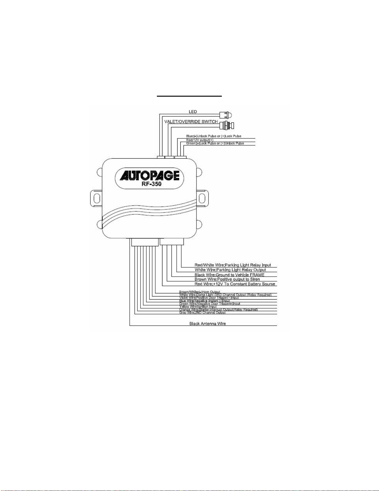
WIRING DIAGRAM
3
H1: MAIN 5 PIN WIRE HARNESS:
5. Red Wire: +12V To Constant Battery Source
4. Brown Wire: Positive output To
3. Black Wire: Ground to Vehicle FRAME
2. White Wire: Parking Light Relay Output
1. Red / White Wire: Parking Light Relay input
Siren
+12V
Splice
To Door
Lock Motor To Slave Door
Lock switches
3 Pin Plug
To Alarm
30
87
87
+12V
Blue Wire
H2: 8 PIN MINI CONNECTOR WIRE HARNESS:
1. BROWN/WHITE ...(-) HORN OUTPUT
2. WHITE...DOME LIGHT / 3RD CHANNEL OUTPUT
3. VIOLET...POSITIVE DOOR TRIGGER (+) INPUT
4. BLUE...NEGATIVE INSTANT (-) INPUT
5. GREEN...NEGATIVE DOOR TRIGGER (-) INPUT
6. YELLOW...IGNITION INPUT
7. ORANGE...STARTER INTERUPT OUTPUT
8. GRAY ...2ND CHANNEL OUTPUT
(RELAY REQUIRED)
(RELAY REQUIRED)
Siren and Starter Kill relay optional
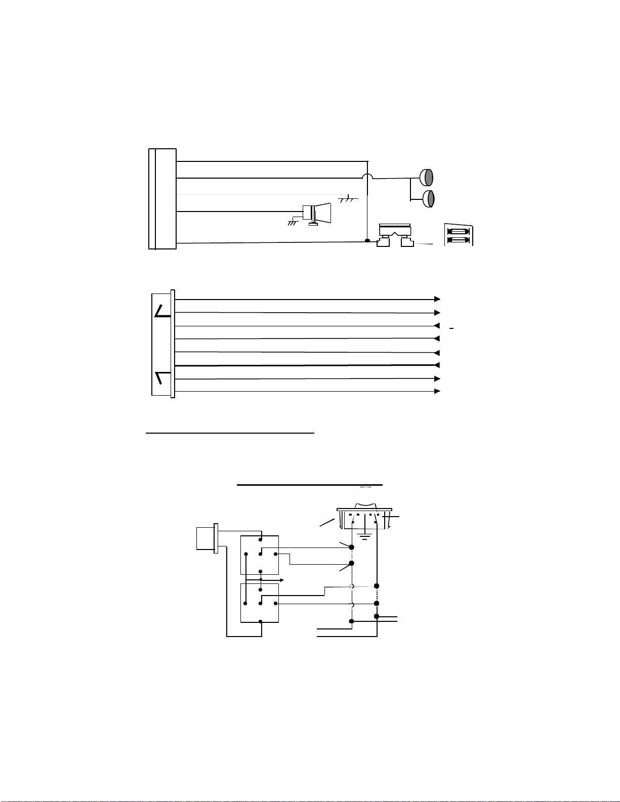
DOOR LOCK DIAGRAMS
15A Fuse
*
5-WIRE ALTERNATING DOOR LOCK
Green Wire
87a
87a
86
85
86
85
Master Door
Lock Switch
30
Splice
Cut the Existing
Unlock Wire
Cut the Existing
X
Lock Wire
4
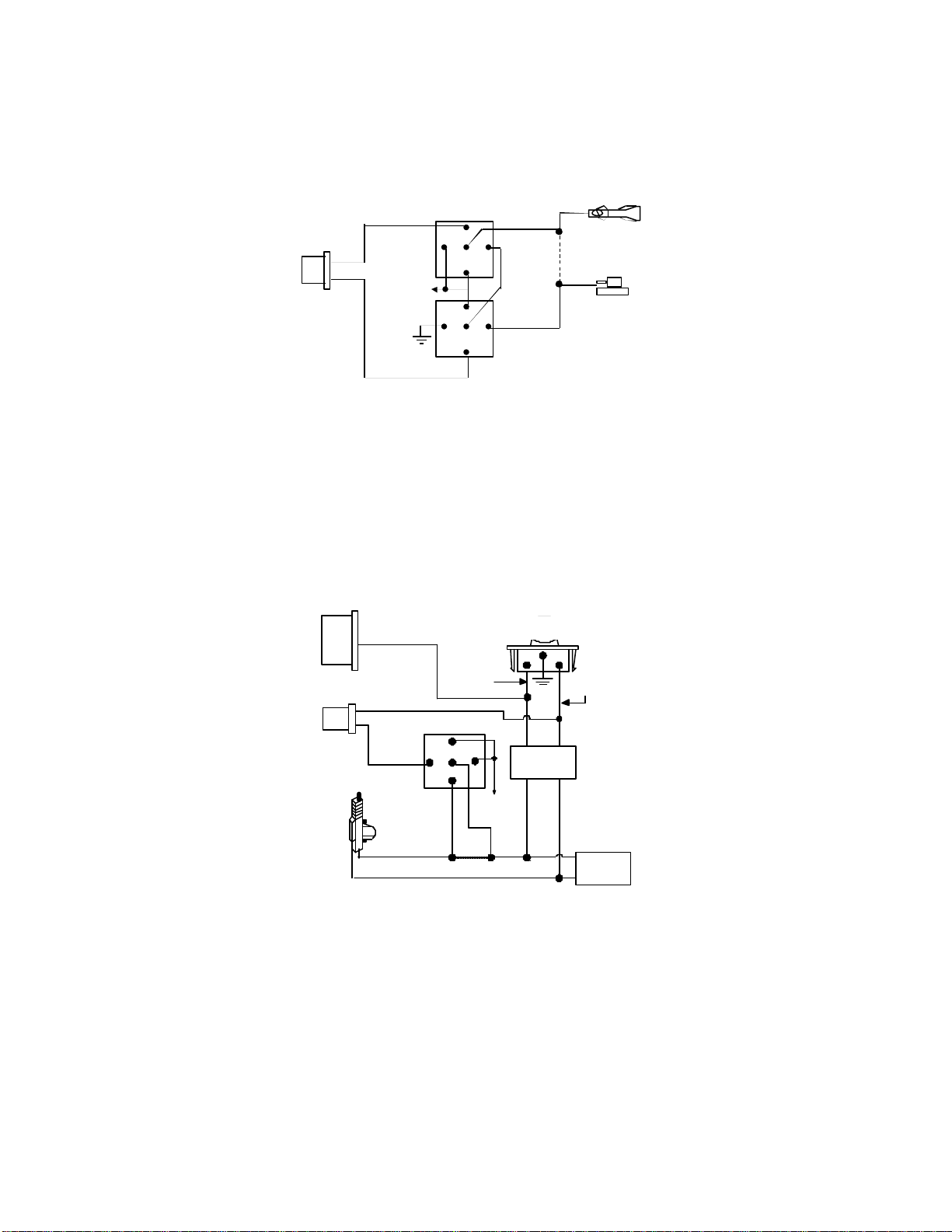
VACUUM OPERATED CENTRAL LOCKING
30
87a
X
30 85 87
OEM Door
Green Wire
3 Pin
Plug To
Alarm
+12V
Blue Wire
VACUUM OPERATED DOOR LOCKING SYSTEM:
86
30
87a
87
85
86
87
85
Cut
X
Door Switch
Compressor
TYPICAL OF MERCEDES BENZ AND AUDI.
Locate the wire under the driver's kick panel. Use the
voltmeter connecting to ground, verify that you have the
correct wire with the doors unlocked, the voltmeter will
receive "12 volts". Lock the doors and the voltmeter will
read "0 volt". Move the alligator clip to +12V and the
voltmeter will receive "12 volts". Cut this wire and make
connections. Be sure to program door lock timer to
3.5 seconds.(See Feature II – 3 Programming.)
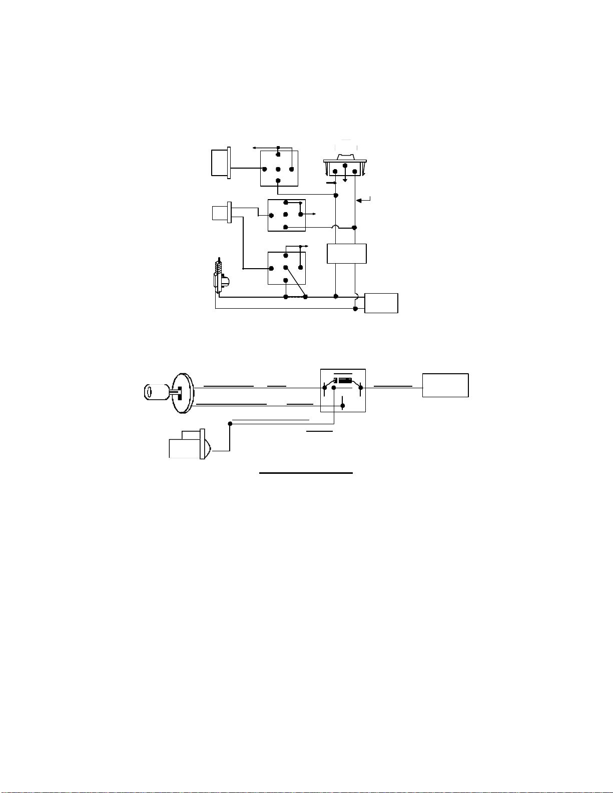
2 STEP DOOR UNLOCK WIRE CONNECTION FOR
GROUND SWITCHED DOOR LOCKS
8-Pin
Plug
From
Alarm
3 Pin Plug
To Alarm
H2/8 Gray Wire
H3/3 Green
Wire
Door Lock
OEM Door Master Lock Switch
Unlock
Existing Neg.
Unlock Wire
Lock
Existing Neg.
Lock Wire
H3/1 Blue
Wire
Door Unlock
OEM
Door Lock
Motor
86
87A
+ 12V
Cut Existing Unlock
Lock Relay
To All Other
Door Lock
Motors
5
2 STEP DOOR UNLOCK WIRE CONNECTION FOR
Existing Pos.
86 85
OEM Door
Lock Relay
30 85 87
Wire
30 85 87
86 85
POSITIVE SWITCHED DOOR LOCKS
8-Pin
H2/8
Plug
Gray Wire
From
Alarm
H3/3 Green
Door Lock
H3/1 Blue
Wire
Door Unlock
OEM Driver's
Door Lock
Motor
+12V
87
87A
30
86
86
Cut Existing Unlock
OEM Door Master Lock Switch
Unlock
Existing Pos.
Unlock Wire
87A
+ 12V
87A
X
+ 12V
+ 12V
Lock
Lock Wire
To All Other
Door Lock
Motors
STARTER DISABLE ( Optional )
<Purple>
RK-1
87a
30
87
<White Wire>
Orange
Starter Disable
Wire
<12V (+) Ignition> <Red>
<Starter Wire (key side)>
<Starter Wire (motor side)>
<Yellow>
STARTER
PROGRAMMING
PROGRAMMING TRANSMITTERS:
Enter:
1. Turn the Ignition 'switch ‘OFF/ON’ 3 TIMES and stay in ON position.
Within 15 seconds,
2. Push the Valet switch 2 times and hold in on the 2nd push. When a
long chirp is heard release the valet switch. You are now in the
Transmitter programming mode.
Program:
1. Press any button on the first transmitter until the siren responds with
a confirming chirp. The firs t transmitter is now programmed.
2. Press any button on the second transmitter until the siren responds
with a confirming chirp. The second transmitter is now programmed.
3. Apply the same procedure to program any 3rd or 4th transmitter.
Exit: Turn Ignition to the 'OFF' position, or leave it for 15 seconds. 3 long
chirps will confirm exit.
 Loading...