


C3-RS1100 OLED
PROFESSIONAL 2-WAY 915 MHz. OLED REMOTE
CAR STARTER & 6 CHANNEL ALARM SYSTEM
With
Built-in Temperature Sensor
And Two Way Serial Port Data Link
INSTALLATION MANUAL
Compatible
THIS PRODUCT IS DESIGNED FOR PROFESSIONAL INSTALLATION ONLY
C3 RS1100REV. A |
1 |

TABLE OF CONTENTS:
INSTALLATION DIAGRAMS |
4 |
|
H1: 6 PIN HEAVY GAUGE WIRING CONNECTION |
6 |
|
H1/1 Violet Wire – Starter Output |
6 |
|
H1/2 & H1/3 Red Wire – +12V Power Input |
7 |
|
H1/4 Yellow Wire – Ignition 1 Output |
7 |
|
H1/5 Pink Wire – Ignition 2 Output |
7 |
|
H1/6 Brown Wire – Accessory Output (Heater /ACC Output) |
7 |
|
H5: 5 PIN WHITE WIRE HARNESS |
8 |
|
H5/1 Red / White wire – Parking Light Relay Power Input |
8 |
|
H5/2 White wire – Parking Light Relay Output |
8 |
|
H5/3 Black wire – System Ground |
8 |
|
H5/4 Brown wire – Siren Drive Output |
8 |
|
H5/5 Red wire – System Power |
8 |
|
H7: 4-PIN BLACK CONNECTOR TWO-WAY TRANSCEIVER/ANTENNA MODULE |
9 |
|
H8. 2 PIN BLUE CONNECTOR FOR THE VALET SWITCH |
9 |
|
H3. 2 PIN WHITE CONNECTOR FOR THE LED STATUS INDICATOR |
9 |
|
H9. 4 PIN ORANGE CONNECTOR FOR 2 STAGE SHOCK SENSOR (ZONE 1/4) |
10 |
|
H6: 22 PIN WIRE CONNECTOR |
10 |
|
H2 C3 SERIAL DATA PORT CONNECTION RS -232 Port |
16 |
|
H4. 3 PIN DOOR LOCK CONNECTOR (maximum 500 mA output) |
17 |
|
Negative Trigger Door Lock System |
17 |
|
Positive Trigger Door Lock System |
17 |
|
Alternating Door Lock System |
17 |
|
Vacuum Operate Door Locking System |
17 |
|
2 Steps Door Unlock Wire Connection -5 Wires Alternating Lock System |
18 |
|
2 Steps Door Unlock Wire Connection - (-) Switched Door Lock System |
18 |
|
2 Steps Door Unlock Wire Connection - (+) Switched Door Lock System |
18 |
|
|
|
|
|
PROGRAMMING & TESTING: |
|
|
PROGRAMMING THE REMOTE TRANSMITTER |
19 |
|
FEATURES PROGRAMMING |
19 |
|
Alarm Feature “A” Programming |
19 |
|
Alarm Feature “B” Programming |
20 |
|
Alarm Feature “C” Programming |
22 |
|
Channel 4 Timer Control Output Programming |
23 |
|
Password Pin Code Setup |
24 |
|
Start Feature “D” Programming |
24 |
|
Start Feature “E” Programming |
25 |
|
Tachometer Checking Type – RPM Learning & Testing |
26 |
|
Voltage Checking Type – Start Timer Set-up & Testing |
27 |
|
Timer Checking Type – Start Timer Set-up & Testing |
28 |
|
Test Mode |
28 |
|
RETURN TO FACTORY DEFAULT SETTING |
29 |
|
TROUBLE SHOOTING |
30 |
|
SHUTDOWN DIAGNOSTICS |
30 |
|
TESTING YOUR INSTALLATION |
30 |
|
Test the Brake shutdown circuit |
31 |
|
Test the Hood Pin shutdown circuit |
31 |
|
Neutral Start Safety Test |
31 |
C3 RS1100REV. A |
2 |

Mechanical Neutral Safety Switch Considerations |
31 |
Park/Neutral ECM Input |
31 |
Key In Sensor Circuits |
32 |
INTRODUCTION
This Remote Starter with Alarm and Keyless Entry System has been designed to be installed on fuel-injected vehicles with an automatic transmission ONLY.
nNever install this remote starter on a manual transmission vehicle.
nThis system must be installed and wired through a safety switch so it will not start in any forward or reverse gear.
nSome automatic transmission vehicles mainly older GM vehicles with a purple starter wire have a mechanical-type park safety switch instead of electrical safety switch. The mechanical type does not interrupt the starter circuit when the transmission is in any gear and does not offer the 100% level of safety required for remote starting purposes. Therefore, our system should never be installed on any vehicle that uses a mechanical type park safety switch.
nOnce you install this system, you must verify that the vehicle will not start in any forward or reverse gear, regardless of the type of vehicle.
nRead the operation manual for operating.
nDo not install any component near the brake, gas pedal or steering linkage.
nSome vehicles have a factory installed transponder immobilizer system that can severely complicate the installation. There is a possibility that this system cannot be installed on some immobilizer-equipped vehicles.
nMost vehicles have an SRS air bag system. Use extreme care and do not probe any wires of the SRS system.
nDisconnect the car battery before beginning work on the vehicle.
nCheck behind panels before drilling any holes. Ensure that no wiring harness or other components are located behind the panels that would otherwise be damaged.
nDo not use conventional crimp lock, bullet on any wiring. Poor wiring, i.e. taped joints will possibly introduce unreliability into the alarm system and may result in false alarms or incorrect operation. We suggest soldering all connection points.
nInstall the wiring neatly under carpets or behind trim to prevent possible damage to wires.
C3 RS1100REV. A |
3 |

INSTALLATION DIAGRAM
C3 RS1100REV. A |
4 |
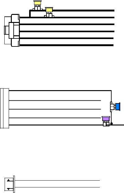
H1 6 PIN HEAVY GAUGE WIRE HARNESS
20A
Red: Remote Start Power 1
20A
Red: Remote Start Power 2
Violet: Starter (+) Output
Pink: Ignition 2 (+) Output
Yellow: Ignition 1 (+) Output
Brown: Acc/Heater (+) Output
H5 5 PIN WIRE HARNESS
Red/White: Parking Light Relay Power Input
White: Parking Light Relay Output
Black: System Main Ground (-)
Brown: Siren (+) Output
Red: 12v + Battery Power
H4. 3 PIN, DOOR LOCK CONNECTOR
1. Blue Wire |
( - ) Unlock Pulse |
|
(+) Lock Pulse |
||
3. Green Wire |
( - ) Lock Pulse |
|
( + ) Unlock Pulse |
||
|
C3 RS1100REV. A |
5 |

WIRING
Keep wiring away from moving engine parts, exhaust pipes and high-tension cable. Be sure to tape wires that pass through holes on the firewall to prevent fraying.
CAUTION: Do not connect the wire harness to the control module until all wiring to vehicle is complete.
H1: 6 PIN HEAVY GAUGE WIRING CONNECTIONS:
Remember that what the system does to start a vehicle is to duplicate the functions of the ignition key switch! Below, we will explain the three basic functions of the ignition switch. Since this installation will require analysis of the ignition switch functions, we recommend making the three connections below at the ignition switch harness directly.
Violet Wire —Starter Output
Careful consideration for the connection of this wire must be made to prevent the vehicle from starting while in gear. Understanding the difference between a mechanical and an electrical Neutral Start Switch will allow you to properly identify the circuit and select the correct installation method. In addition you will realize why the connection of the safety wire is required for all mechanical switch configurations.
Failure to make this connection properly can result in persona l injury and property damage.
In all installations it is the responsibility of the installing technician to test the remote start unit and assure that the vehicle can not start via RF control in any gear selection other than park or neutral.
In both mechanical and electrical neutral start switch configurations, the connection of the VIOLET wire will be made to the low current start solenoid wire of the ignition switch harness. This wire has +12 volts when the ignition switch is turned to the “START” (CRANK) position only. This wire has 0 volts in all other ignition switch positions.
NOTE: This wire must be connected to the vehicle side of the starter cut relay (when used). For the electrical neutral switch configuration, this connection must be made between the starter inhibit relay (when used) and the neutral safety switch as shown in the following diagram. Failure to connect this wire to the ignition switch side of the neutral safety switch can result in personal injury and property damage.
SEE NEUTRAL START SAFETY TEST FOR FURTHER DETAILS.
|
|
VIOLET Wire |
|
|
“Off” |
“On” |
|
Neutral Safety |
Starter |
|
|
|||
“Acc” |
“Start” |
|
Switch |
|
|
|
|
||
Ignition |
|
|
|
|
Switch |
|
|
|
|
|
|
Start Cut Relay |
Closed in Park or |
|
|
|
(When Used) |
|
|
|
|
Neutral Only |
|
|
|
|
|
|
|
C3 RS1100REV. A |
6 |
Red Wire (2) — +12V Power Input
Remove the two 20A fuses prior to connecting these wires and do not replace them until the satellite has been plugged into the control module. These wires are the source of current for all the circuits the relay satellite will energize. They must be connected to a high current source. Since the factory supplies (+) 12V to the key switch that is used to operate the motor, it is recommended that these wires be connected there.
Note: If the factory supplies two separate (+) 12V feeds to the ignition switch, connect one RED wire of the satellite to each feed at the switch.
Yellow Wire – Ignition 1 Output
Connect the YELLOW wire to the ignition 1 wire from the ignition switch. The ignition wire should receive “12 volts” when the ignition key is in the “ON” or “RUN” and “START” or “CRANK” position. When the ignition is turned “OFF”, the ignition wire should receive “0” voltage. The YELLOW wire must be connected.
PINK Wire – Ignition 2 Output
Some vehicles have [2] ignition wires that must be power. Connect the PINK wire to the ignition 2 wire from the ignition switch. The ignition wire should receive “12 volts” when the ignition key is in the “ON” or “RUN” and “START” or “CRANK” position. When the ignition is turned “OFF”, the ignition wire should receive “0” voltage. If the PINK wire is not used, cap the end of the wire.
Brown Wire –Accessory Output (Heater /AC Output)
Connect the BROWN wire to the accessory wire in the vehicle that powers the climate control system.
An accessory wire will show + 12 volts when the ignition switch is turned to the “ACCESSORY” or “ON” and “RUN” positions, and will show 0 Volts when the key is turned to the “OFF” and “START” or “CRANK” position. There will often be more than one accessory wire in the ignition harness. The correct accessory wire will provide power to the vehicle’s climate control system. Some vehicles may have separate wires for the blower motor and the air conditioning compressor. In such cases, it will be necessary to add a relay to power the second accessory wire.
H2 RS232 C3 Two way SERIAL DATA PORT CONNECTION:
This connector is to be used for Serial Data communications with idatalink modules by Auto Page only! DO NOT CONNECT THIS TO ANY OTHER WIRING!
This connector will transmit digital codes to operate all functions of Autopage data modules. When these modules are used, no other data bus connections need to be made to the RS -900. The Data Bus module will receive its commands directly from the CPU of the RS -900. This will provide greater theft protection as well as aid in the installation of this product. The RS -232 serial harness is provided with all Autopage serial data modules and is not included with the RS-900. This two-way data port has
C3 RS1100REV. A |
7 |
been designed for use with all C I 3 compatible components. C I 3 Telematics system is available at any authorized Autopage dealer.
This port will only operate correctly with Autopage C3 I-Datalink Modules.
H3. 2 PIN WHITE CONNECTOR (THE LED STATUS INDICATOR):
The led indicator status should be mounted in a highly visible area such as top of the dashboard, on top of the shifter console or on the dashboard face. Leave at least 6mm space behind the mounting location for LED housing. Once a suitable location is chosen, drill a 6mm hole. Run the LED wires through the hole then press the 2 pin LED housing into place. Route the LED wires to the control module.
H5: 5 PIN WIRE HARNESS:
RED / WHITE WIRE –PARKING LIGHT RELAY INPUT —
The RED/WHITE wire is the input to the flashing parking light relay. The connection of the RED/WHITE wire will determine the output polarity of the flashing parking light relay.
If the vehicle you are working on has +12volt switched parking lights, you don’t need connect this wire. This wire is already connected to +12volt.
If the vehicle’s parking lights are ground switched, cut the RED/WHITE wire, connect the RED/WHITE wire to chassis ground.
WHITE WIRE — PARKING LIGHT RELAY OUTPUT (+12 V 10A OUTPUT) —
Connect the WHITEwire to the parking light wire coming from the headlight switch. Do not connect the WHITE wire to the dashboard lighting dimmer switch. (Damage to the dimmer will result). The limitation of the WHITE wire is 10 AMP max. Do not exceed this limit or damage to the alarm and parking relay will result.
BLACK WIRE — SYSTEM GROUND –
This is the main ground connection of the alarm module. Make this connection to a solid section of the vehicle frame. Do not connect this wire to any existing ground wires supplied bythe factory wire loom, make the connection to the vehicle’s frame directly.
BROWN WIRE – (+) SIREN OUTPUT –
This wire is provides power to the supplied siren. Connect the Brown wire to the Red wire of the siren. Connect the Black wire of the siren to a stable chassis ground.
RED WIRE — SYSTEM POWER (+12V CONSTANT) —
The RED wire supplies power to the system. Connect this wire to a stable constant +12 volt source.
C3 RS1100REV. A |
8 |
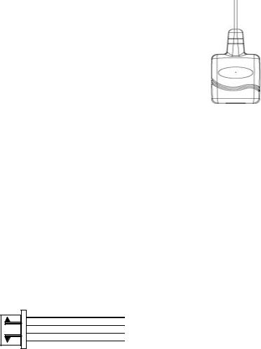
H7. 4-PIN BLACK CONNECTOR. – TWO-WAY TRANSCEIVER/ANTENNA MODULE
The Two-way transceiver/antenna mounting location should be the upper left or lower left corner of driver’s windshield. For optimum range we suggest that the antenna be mounted Antenna tip facing down.
Warning!
Do not mount in such a manner that it obstructs the driver’s view.
-Remove the protective tape backing.
-Carefully align the two-way transceiver/antenna and apply to windshield.
-Route the black connector wire behind the trim and connect to the two-way transceiver/antenna.
-Connect the other end to the control module.
-Special considerations must be made for windshield glass as some newer vehicles utilize a metal-shielded window glass that will inhibit or restrict RF reception. In these vehicles, route the two ways transceiver/antenna module away from metallic s hielded window glass as far as possible.
H8. 2 PIN BLUE CONNECTOR FOR THE VALET SWITCH:
Select a mounting location for the switch that is easily accessible to the driver of the vehicle. The switch does not have to be concealed, however, concealing the switch is always recommended, as this provides an even higher level of security to the vehicle. Mount the valet switch in a hidden but accessible location. Route the valet switch wires to the control module.
H9. 4 PIN ORANGE CONNECTOR 2 STAGE SHOCK SENSOR (ZONE 1 / 4)
1. Green Wire / Zone 1 Warn Away Input 2. Blue Wire / Zone 4 Ground Trigger
3. Black Wire / Ground
4. Red Wire / +12Volts
C3 RS1100REV. A |
9 |
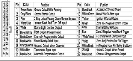
H6: 22 PIN WIRE CONNECTORS:
H6/1 BROWN/BLACK WIRE: 200 mA (-) Ground Output When Running.
This wire provides a negative output during the remote start process. It can be used to operate by-pass modules that may be required in your installation. This wire will provide ground once the remote start process has been initiated and will remain grounded while the engine is running
H6/2 GRAY/BLACK WIRE: 200 mA (-) Second Starter Output.
This line can be used if a second starter line is needed. Some vehicles require a two-starter line to remote start. This wire provides a negative output that will work the same way as the Violet starter line in connector H1.
H6/3 Pink wire – (-) 200mA Programmable Output 2 Steps Unlock Output (Factory default setting) (See Alarm Feature C – 1 Programming)
The 2 steps unlock feature will work for the most fully electronic door lock circuit. The vehicle must have an electronic door lock switch (not the lock knob or key switch), which locks and unlocks all of vehicle's doors. When wired for this feature, press the disarm (or unlock) button one time will disarm the alarm and unlock the driver's door only. If, press disarm (or unlock) button two times within 3 seconds, the alarm will disarm and all doors will unlock.
Factory Security Disarm Signal Output –
This wire is designed to disarm a factory installed security system. This wire sends a negative (-) 1 seconds pulse upon a remote start and remote door unlocking. Some factory systems must be disarmed to allow remote starting. In most cases, this wire may be connected directly to the factory alarm disarm wire. The correct wire will show negative ground when the key is used to unlock the doors or trunk. This wire is usually found in the kick panel area in the wiring harness coming into the car body from the door.
Start Status (Shock Sensor By-Pass Control) Output–
This wire is designed to by-pass shock sensor module. This wire will supply an output at all times the remote start is operating plus an additional 3 seconds after the remote start unit turn off.
Key Sensor By -Pass Output –
C3 RS1100REV. A |
10 |
This output is for a Key Sense wire by -pass that some Chrysler and Toyota vehicles need to activate remote start. This wire comes on when remote start is activated and stays on for 20 seconds.
H6/4 White / Bule wire – (-) Instant Start & Turn Off Input –
This wires activates and turns off the remote starter each time it sees a momentary ground signal. Normally used for testing during installation or when activating the module from an after-market system.
H6/5 White wire – (-) 200mA Dome Light Control Output –
This wire becomes grounded when |
|
|
|
Fuse |
|
|
|
|
|
|
|||
the dome light controls circuit active. |
|
|
|
|
Courtesy |
||||||||
|
|
|
|
|
|
|
|
||||||
|
|
|
|
|
|
|
|||||||
The current capacity of this wire is |
|
|
|
|
|
|
|
|
Light |
||||
|
|
|
|
|
|
|
Door |
||||||
200mA. This wire can control the |
|
|
|
87 |
|
|
|
Switch |
|
|
|
|
|
|
|
|
|
|
|
|
|
||||||
operation of the interior lights. An |
White Wire |
86 |
87a 85 |
|
|
+12V |
|
|
|
|
|
||
|
|
|
|
|
|
|
|||||||
optional 10 Amps relay can be used to |
|
|
|
|
|
|
|
|
|||||
this system for interior lights |
|
|
30 |
|
|
|
|
|
|
|
|
|
|
|
|
|
|
|
|
|
|
|
|
|
|
|
|
|
|
|
|
|
|
|
|
|
|
|
|
|
|
operation. |
|
|
|
|
|
|
|
|
|
|
|
|
|
a). Upon disarming, the interior lights will remain on for 30 seconds. |
|
|
|
|
|
|
|||||||
b). If the alarm is triggered, the interior light will flash for the same duration as the siren.
H6/6 Brown / White wire – (-) 200mA Programmable Output Horn Output –
(Factory default setting) |
|
|
|
|
|
|
|
|
|
This wire is provided to use the existing |
|
|
|
|
FUSE |
To horn |
|
|
|
vehicle's horn as the alarm system's |
|
|
|
|
|
|
|
|
|
optional's warning audible device. It's a |
Brown/White |
|
|
|
|
|
|
|
|
|
|
|
|
|
|
|
|
||
transistorized low current output, and |
87 |
|
|
+ 12 V |
|||||
wire |
|
|
|||||||
should only be connected to the low |
|
86 87a 85 |
+12V Or Ground |
||||||
current ground output from the vehicle's |
|
|
|
30 |
|
||||
|
|
|
Depending On System |
||||||
horn switch. When the system is |
|
|
|
|
|
|
Requirements |
||
|
|
|
|
|
|
||||
triggered, the horn will sound. |
|
|
|
|
|
|
|
|
|
Factory Security Rearm Signal Output –(See Alarm Feature C – 2 Programming) – This output is programmable. If programmed rearm a factory installed security
system. This wire will supply a pulse whenever the remote start times out or is shut dowm using the transmitter and remote door locking.
H6/7 Black/Green wire – (-) 200mA Timer Control Channel 4
See Alarm Feature C – 5 Programming) Channel 4 Output (Factory default setting on momentary ground ed)
This wire is built-in user -programmable timer output provides a ground through this wire. Press the transmitter  and
and  buttons at the same time. You may program the built-in timer to send a ground signal for any time interval between 1 second and 2 minutes. For instance, this timer output may be used to turn on the headlight with the remote control. Also on certain BMW, Mercedes Benz, Jaguar and Volkswagen cars, you can use this unique timed output to allow remote closure of all power window and sunroof without the need for an external module!
H6/8 Black/White wire – (-) Neutral Safety Switch Input or (-) Enable Switch Input –
C3 RS1100REV. A |
11 |
When the BLACK/WHITE wire is grounded, the remote start unit is operable. When this wire is open from ground, the remote start is disabled.
1. The optional “remote start toggle switch” can be added on to temporarily disable the Remote Start Device, it can prevent the vehicle from being remote started accidentally. This feature is useful if the vehicle is being serviced or stored in an enclosed area. To disable the remote start, move the optional remote start enable toggle switch to the OFF position. To enable the remote start, move the optional remote start enable toggle switch to the ON position.
2. If needed, this wire can connect to the PARK/NEUTRAL switch in the vehicle. (See the TESTING YOUR INSTALLATION GUIDE)
IMPORTANT NOTE: This wire must have a “GROUND” to operate remote start.
H6/9 Orange/White wire – 200mA Grounded Output when Disarmed - N.O. Disable This wire will become grounded when the alarm is disarmed. The current capacity of this wire is 200mA. It can be connected to optional Ignition disable relay / ECU disable relay / Fuel Pump disable relay.
H6/10 White / Red wire – Tachometer Signal Connection –
Note: You should connect this wire if you program the Start Feature E – 2 to “Tachometer checking type”, otherwise do not connect this wire and tap the end. Note: No connection of this wire is required, if you use the voltage or timer checking type mode.
This input provides the remote start system with information about the engine’s revolutions per minute (RPM). It can be connected to the negative side of the coil in vehicle with conventional coils. In multi -coil and high energy ignition system locating a proper signal may be more difficult. Once connected,
To test for a tachometer wire, a multi -meter capable of test AC voltage must be used. The tachometer wire will show between 1V and 6V AC at idle, and will increase as engine RPM increases. In multi -coil ignition system, the system can learn individual coil wire. Individual coil wires in a multi -coil ignition system will register lower amounts of AC voltage. Also, if necessary, the system can use a fuel injector control wire for engine speed sensing. Common locations for a tachometer wire are the ignition coil itself, the back of the gauges, engine computers, and automatic transmission computers.
IMPORTANT! Do not test tachometer wires with a test light or logic probe. The vehicle will be damaged.
How to find a tachometer wire with your multi -meter 1. Set the ACV or AC voltage (12V or 20V is fine.)
2. Attach the (-) probe of the meter to chassis ground. 3. Start and run the vehicle.
4. Probe the wire you suspect of being the tachometer wire with the red probe of the meter.
5. If this is the correct wire the meter will read between 1V and 6V.
IMPORTANT NOTE: M ust program the “Tach Signal” before trying to remote start.
H6/11 Black / Violet Wire– (-) 200mA Timer Control Channel 6 (See Alarm Feature C – 7 Programming)
This wire is built-in user-programmable timer output provides a ground through this wire. Press the transmitter  and
and  buttons at the same time. You may program the built-in timer to send a ground signal for any time interval between 1 second and 2 minutes. For instance, this timer output may be used to turn on the headlight with the remote control.
C3 RS1100REV. A |
12 |
 Loading...