


ASUS V7700 User Manual

R
V7700 Series
GigaTexel Shader Graphics Card
USER’S MANUAL
Hardware & Video Drivers
V7700
/ 32MB
V7700 / 64MB
V7700 / T / 32MB
V7700 / T / 64MB
V7700 Deluxe / 32MB
V7700 Deluxe TV / 32MB
V7700 Pro / 64MB
V7700 Pro / T / 64MB
V7700 Pro / Deluxe / 64MB
V7700 TI / 64MB / 32MB
V7700 TI / T / 64MB / 32MB
V7700 TI / Deluxe / 64MB / 32MB

USER’S NOTICE
No part of this manual, including the products and software described in it, may be reproduced, transmitted, transcribed, stored in a retrieval system, or translated into any language
in any form or by any means, except documentation kept by the purchaser for backup purposes, without the express written permission of ASUSTeK COMPUTER INC. (“ASUS”).
ASUS PROVIDES THIS MANUAL “AS IS” WITHOUT WARRANTY OF ANY KIND,
EITHER EXPRESS OR IMPLIED, INCLUDING BUT NOT LIMITED TO THE IMPLIED
W ARRANTIES OR CONDITIONS OF MERCHANTABILITY OR FITNESS FOR A PARTICULAR PURPOSE. IN NO EVENT SHALL ASUS, ITS DIRECTORS, OFFICERS,
EMPLOYEES OR AGENTS BE LIABLE FOR ANY INDIRECT, SPECIAL, INCIDENTAL, OR CONSEQUENTIAL DAMAGES (INCLUDING DAMAGES FOR LOSS OF
PROFITS, LOSS OF BUSINESS, LOSS OF USE OR DATA, INTERRUPTION OF BUSINESS AND THE LIKE), EVEN IF ASUS HAS BEEN ADVISED OF THE POSSIBILITY
OF SUCH DAMAGES ARISING FROM ANY DEFECT OR ERROR IN THIS MANUAL
OR PRODUCT.
Product warranty or service will not be extended if: (1) the product is repaired, modified or
altered, unless such repair, modification of alteration is authorized in writing by ASUS; or
(2) the serial number of the product is defaced or missing.
Products and corporate names appearing in this manual may or may not be registered trademarks or copyrights of their respective companies, and are used only for identification or
explanation and to the owners’ benefit, without intent to infringe.
• NVIDIA, GeForce 256, GTS and combinations thereof are trademarks of NVIDIA Corporation.
• Windows, MS-DOS, and DirectX are registered trademarks of Microsoft Corporation.
• Adobe and Acrobat are registered trademarks of Adobe Systems Incorporated.
The product name and revision number are both printed on the product itself. Manual revi-
sions are released for each product design represented by the digit before and after the period
of the manual revision number. Manual updates are represented by the third digit in the
manual revision number.
For previous or updated manuals, BIOS, drivers, or product release information, contact ASUS
at http://www.asus.com.tw or through any of the means indicated on the following page.
SPECIFICATIONS AND INFORMATION CONTAINED IN THIS MANUAL ARE FURNISHED FOR INFORMATIONAL USE ONLY, AND ARE SUBJECT TO CHANGE AT
ANY TIME WITHOUT NOTICE, AND SHOULD NOT BE CONSTRUED AS A COMMITMENT BY ASUS. ASUS ASSUMES NO RESPONSIBILITY OR LIABILITY FOR
ANY ERRORS OR INACCURACIES THA T MA Y APPEAR IN THIS MANUAL, INCLUDING THE PRODUCTS AND SOFTWARE DESCRIBED IN IT.
Copyright © 2001 ASUSTeK COMPUTER INC. All Rights Reserved.
Product Name: ASUS V7700 Series
Manual Revision: 1.03 E879
Release Date: September 2001
2
ASUS V7700 Series User’s Manual

ASUS CONTACT INFORMATION
ASUSTeK COMPUTER INC. (Asia-Pacific)
Marketing
Address: 150 Li-Te Road, Peitou, Taipei, Taiwan 112
Telephone: +886-2-2894-3447
Fax: +886-2-2894-3449
Email: info@asus.com.tw
Technical Support
MB/Others (Tel): +886-2-2890-7121 (English)
Notebook (Tel): +886-2-2890-7122 (English)
Desktop/Server (Tel): +886-2-2890-7123 (English)
Fax: +886-2-2890-7698
Email: tsd@asus.com.tw
WWW: www.asus.com.tw
FTP: ftp.asus.com.tw/pub/ASUS
ASUS COMPUTER INTERNATIONAL (America)
Marketing
Address: 6737 Mowry Avenue, Mowry Business Center, Building 2
Newark, CA 94560, USA
Fax: +1-510-608-4555
Email: tmd1@asus.com
Technical Support
Fax: +1-510-608-4555
Email: tsd@asus.com
WWW: www.asus.com
FTP: ftp.asus.com/Pub/ASUS
ASUS COMPUTER GmbH (Europe)
Marketing
Address: Harkortstr. 25, 40880 Ratingen, BRD, Germany
Fax: +49-2102-442066
Email: sales@asuscom.de (for marketing requests only)
Technical Support
Hotline: MB/Others: +49-2102-9599-0 Notebook: +49-2102-9599-10
Fax: +49-2102-9599-11
Support (Email): www.asuscom.de/de/support (for online support)
WWW: www.asuscom.de
FTP: ftp.asuscom.de/pub/ASUSCOM
ASUS V7700 Series User’s Manual 3

CONTENTS
I. Introduction.......................................................................... 7
Available Models .............................................................................7
Highlights.........................................................................................8
Features ............................................................................................8
II. Hardware Setup................................................................... 9
ASUS V7700 Deluxe TV / Deluxe ..................................................9
II. Hardware Setup................................................................. 10
ASUS V7700 / T ............................................................................10
II. Hardware Setup................................................................. 11
ASUS V7700 (Pure VGA) Layout............................................................ 11
ASUS V7700Pro Deluxe........................................................................... 12
ASUS V7700 Pro / T Layout .................................................................... 13
ASUS V7700 Pro (Pure VGA) Layout ..................................................... 14
ASUS V7700 TI / T................................................................................... 15
ASUS V7700 TI (Pure VGA) Layout ....................................................... 16
ASUS V7700 TI Deluxe ........................................................................... 17
ASUS TV77 TV-Out Module (Optional) .................................................. 18
ASUS TV77 TV-Out Module Layout ................................................. 18
ASUS TV77 TV-Out Module Connection .......................................... 18
ASUS VR-100 Optional Upgrade Kit ...........................................19
Installation Procedures...................................................................20
New Systems....................................................................................... 20
Systems with Existing VGA Card....................................................... 20
III. Software Setup ................................................................. 21
Operating System Requirements ...................................................21
Windows 98 ........................................................................................ 21
Display Driver Installation.................................................................. 22
Windows 98 ........................................................................................ 22
Method 1: ASUS Quick Setup Program ....................................... 22
Method 2: Display Property Page................................................. 23
Method 3: Plug and Play .............................................................. 24
Windows 2000 .................................................................................... 25
Method 1: ASUS Quick Setup Program ....................................... 25
Method 2: Plug and Play .............................................................. 26
Windows NT 4.0 ................................................................................. 28
Method 1: Display Property Page................................................. 28
Drivers ...........................................................................................29
Install Display Driver.......................................................................... 29
Install DirectX..................................................................................... 30
Install GART Driver ........................................................................... 31
Install ASUS TW AIN Driver .............................................................. 33
Uninstall Display Driver ..................................................................... 34
4
ASUS V7700 Series User’s Manual

CONTENTS
Windows 98 .................................................................................. 34
Method 1: Using the Autorun Screen ..................................... 34
Method 2: Using Control Panel.............................................. 34
Windows NT 4.0........................................................................... 34
Method 1: Using Control Panel.............................................. 34
Windows 2000 .............................................................................. 35
Method1: Using the Autorun Screen ...................................... 35
Method 2: Using Control Panel.............................................. 35
Run ASUS VGA Live Update............................................................. 36
Install Video for Windows Capture Driver ......................................... 37
Install ASUS Tweak Utility ................................................................ 38
Utilities...........................................................................................38
Install SmartDoctor............................................................................. 39
Install V ideoSecurity........................................................................... 40
Install ASUS Live Utility.................................................................... 41
Install ASUS Digital VCR .................................................................. 42
IV. Software Reference ........................................................... 43
ASUS Control Panel ......................................................................43
Refresh Rate........................................................................................ 43
More Resolution ................................................................................. 44
Information ......................................................................................... 44
Color ................................................................................................... 44
Display ................................................................................................ 48
Direct3D ....................................................................................... 55
OpenGL VR.................................................................................. 58
On Screen Display.................................................................. 59
OpenGL ........................................................................................ 60
Other ............................................................................................. 62
Using the ASUS Utilities ...............................................................63
ASUS Tweak Utility ........................................................................... 63
ASUS V ideoSecurity .......................................................................... 65
ASUS Live Video ............................................................................... 69
ASUS SmartDoctor ........................................................................... 78
ASUS Digital VCR ............................................................................. 81
Using the Other Utilities ................................................................95
ASUS TWAIN Interface ..................................................................... 95
ASUS VR PictureViewer.................................................................... 97
ASUS StereoTV.................................................................................. 99
V. Resolution Table ............................................................... 101
VI. Tr oubleshooting.............................................................. 103
Description...................................................................................103
Recommended Action..................................................................103
ASUS V7700 Series User’s Manual 5

FCC & DOC COMPLIANCE
Federal Communications Commission Statement
This device complies with FCC Rules Part 15. Operation is subject to the following
two conditions:
• This device may not cause harmful interference, and
• This device must accept any interference received, including interference that
may cause undesired operation.
This equipment has been tested and found to comply with the limits for a Class B
digital device, pursuant to Part 15 of the FCC Rules. These limits are designed to
provide reasonable protection against harmful interference in a residential installation. This equipment generates, uses and can radiate radio frequency energy and, if
not installed and used in accordance with manufacturer’s instructions, may cause
harmful interference to radio communications. However, there is no guarantee that
interference will not occur in a particular installation. If this equipment does cause
harmful interference to radio or television reception, which can be determined by
turning the equipment off and on, the user is encouraged to try to correct the inter ference by one or more of the following measures:
• Reorient or relocate the receiving antenna.
• Increase the separation between the equipment and receiver.
• Connect the equipment to an outlet on a circuit different from that to which
the receiver is connected.
• Consult the dealer or an experienced radio/TV technician for help.
WARNING! The use of shielded cables for connection of the monitor to the
graphics card is required to assure compliance with FCC regulations. Changes
or modifications to this unit not expressly approved by the party responsible for
compliance could void the user’s authority to operate this equipment.
Canadian Department of Communications Statement
This digital apparatus does not exceed the Class B limits for radio noise emissions
from digital apparatus set out in the Radio Interference Regulations of the Canadian Department of Communications.
This Class B digital apparatus complies with Canadian ICES-003.
Cet appareil numérique de la classe B est conforme à la norme NMB-003 du Canada.
Macrovision Corporation Product Notice
This product incorporates copyright protection technology that is protected by
method claims of certain U.S. patents and other intellectual property rights owned
by Macrovision Corporation and other rights owners. Use of this copyright protection technology must be authorized by Macrovision Corporation, and is intended
for home and other limited viewing uses only unless otherwise authorized by
Macrovision Corporation. Reverse engineering or disassemby is prohibited.
6
ASUS V7700 Series User’s Manual

I. Introduction
Thank you for purchasing an ASUS V7700 GigaTexel Shader Graphics Card.
With this purchase, you haved joined an elite squadron of graphics
enthusiasts.
Powered by the NVIDIA™ GeForce2 GTS™ graphics processing unit (GPU)
and featuring DDR (Double Data Rate) memory, the ASUS V7700 delivers
cutting-edge graphics performance and superb image fidelity irrespective of
the Central Processing Unit (CPU) used by the PC.
The ASUS V7700 gives you the experience of dynamic, realistic 3D worlds
and characters.
Available Models
Features
I. Introduction
V7700Pro Deluxe
• 64MB DDR Frame Buffer, VGA + Video-
In + TV-Out + 3D Glasses
(ASUS VR-100G Bundled Free)
V7700Pro / T
• 64MB DDR Frame Buffer, VGA + TV -Out
(ASUS VR-100 Upgradeable)
V7700Pro
• 64MB DDR Frame Buffer, Pure VGA
(ASUS VR-100 Upgradeable),
ASUS TV77 TV-Out Module (Optional)
V7700 Deluxe TV
• 32MB DDR Frame Buffer, VGA + VideoIn + TV-Out + 3D Glasses
(ASUS VR-100G Bundled Free) + ASUS
TV Box
V7700 Deluxe
• 32MB DDR Frame Buffer, VGA + VideoIn + TV-Out + 3D Glasses
(ASUS VR-100G Bundled Free)
V7700 / T
• 32/64MB DDR Frame Buffer, VGA + TVOut (ASUS VR-100 Upgradeable)
V7700
• 32/64MB DDR Frame Buffer, Pure VGA
(ASUS VR-100 Upgradeable),
ASUS TV77 TV-Out Module (Optional)
V7700 TI / Deluxe
• 32MB DDR Frame Buffer, VGA + VideoIn + TV-Out + 3D Glasses
(ASUS VR-100G Bundled Free)
V7700 TI / T
• 32/64MB DDR Frame Buffer, VGA + TVOut (ASUS VR-100 Upgradeable)
V7700 TI
• 32/64MB DDR Frame Buffer, Pure VGA
(ASUS VR-100 Upgradeable),
ASUS TV77 TV-Out Module (Optional)
7ASUS V7700 Series User’s Manual

I. Introduction
I. Introduction
Features
Highlights
• Powered by the World’s First Per-
Pixel Shading Graphics
Processing Unit (GPU)
• Built-in 32/64MB DDR video
memory with up to 5.3GB/sec
bandwidth
• Dual-texture pixel-fill capacities
with four new Hypertexel
pipelines
• 1.6 Gtexel fill rate, 25 Mtriangles/
sec through T&L/Setting
• ASUS SmartDoctor™ Technologies
• Optimized for DirectX® 7 and
OpenGL® Features
NVIDIA™ GeForce2 GTS™ /
GeForce2 Pro
Provides more resolutions and color
depths
Sets a new milestone for realism
Performs up tp 3x improvement over
GeForce™
Provide the greatest security to your
valuable system
Ensures broad application support
Features
• AGP 4X/2X with Fast Writes
• Four new Hypertexel pipelines process two texture per pixel, in true color, at full
speed up to 1.6 Gtexel fill rate
• Built-in 32MB high speed DDR video memory with up to 5.3GB/sec bandwidth
• Eight texture mapped, lit pixels per clock cycle
• Second generation Transform and Lighting (T&L) Engine
• Up to 25 million triangles per second at peak rates
• Optimized for Direct3D acceleration with complete support for DirectX 7 fea-
tures, such as multi-texturing, bump mapping, light maps, reflection maps, full
scene anti-aliasing, trilinear and 8-tap anisotropic filtering (better than trilinear
mipmapping)
• Fully 1.2 compliant OpenGL support
• 32-bit colors, Z/stencil buffer
• Multi-buffering (double, triple, quad buffering) for smooth animation and video
playback
• Multiple video windows with hardware color space conversion and filtering (YUV
4:2:2 and 4:2:0)
• Integrated 350MHz RAMDAC supporting from 640x480 up to 2048x1536 in
true color
• BRDF (Bidirectional Reflectance Distribution Function) support
• Video acceleration for Direct Show and MPEG-1, MPEG-2, and Indeo
ASUS V7700 Series User’s Manual8
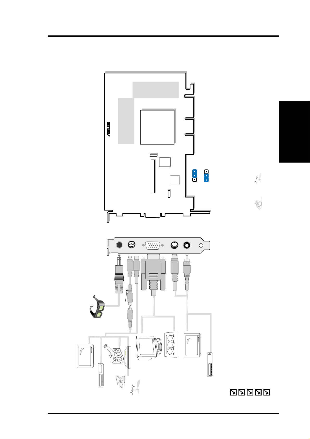
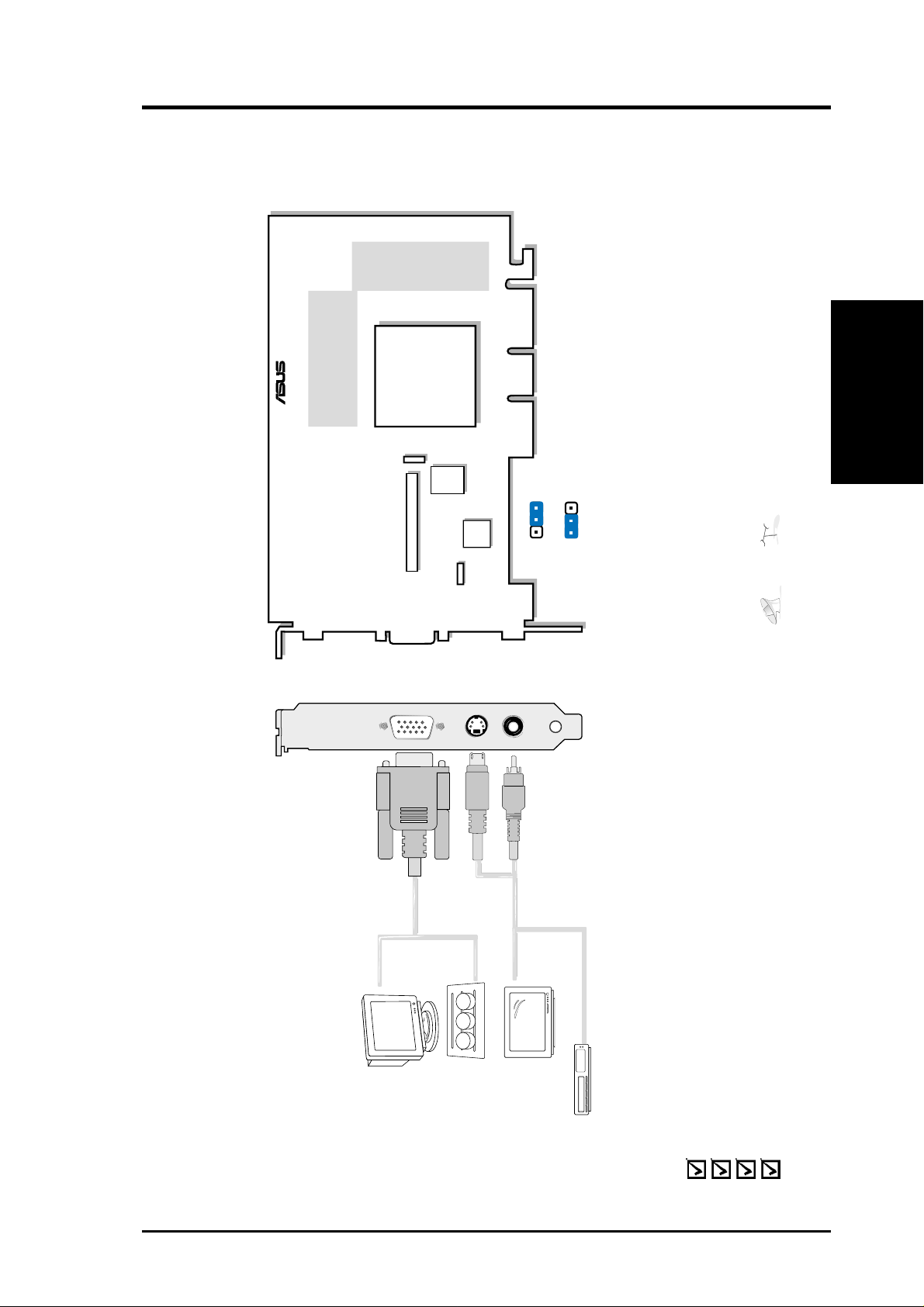
II. Hardware Setup
Stereo Glasses Output
Video Input (ASUS Video) 7pin S compatible)
VGA Output
S-Video Output
Composite (RCA) Output
VGA Monitor
output (15pin)
(standard)
VR Glasses
Output
composite/TV
output (RCA)
CCD/camcorder
input/Tuner/
TV Box Input
(7pin)
SVHS/TV output
(7pin)
Projector
ASUS TV Box
CATV
Composite (RCA) Input
S-Video to Composite Cable
3D Glasses
(ASUS VR-100G)
®
123
123
NTSC
PAL
JP1
JP1
Use the same TV standard for all devices. For example,
if your TV uses the NTSC standard, then you should set
JP1 to “NTSC.”
Digital
PC to TV
Encoder
NVIDIA
TM
GeForce2 GTS
TM
GPU
(Graphics Processing Unit)
Chip with Fan
J1
Fan
Power
The VIP (Video Interface Port) Connector are used for third party add-on modules,
such as video capture cards or television tuners.
VGA
BIOS
®
32/64MB Frame Buffer (DDR)
DDR: Double Data Rate
VIP Connector A
32/64MB DDR Frame Buffer
ASUS V7700 Deluxe TV / Deluxe
V7700 TVR
II. H/W Setup
cannot be connected at the same time.
and
Notes
• Use the same TV standard for all devices.
•
ASUS V7700 TVR Graphics Card (PAL or NTSC)
ASUS TV Box (Deluxe TV Model only)
ASUS VR-100G
This User’s Manual
ASUS V7700 Series Driver & Utility CD Disc
Item Checklist
9ASUS V7700 Series User’s Manual
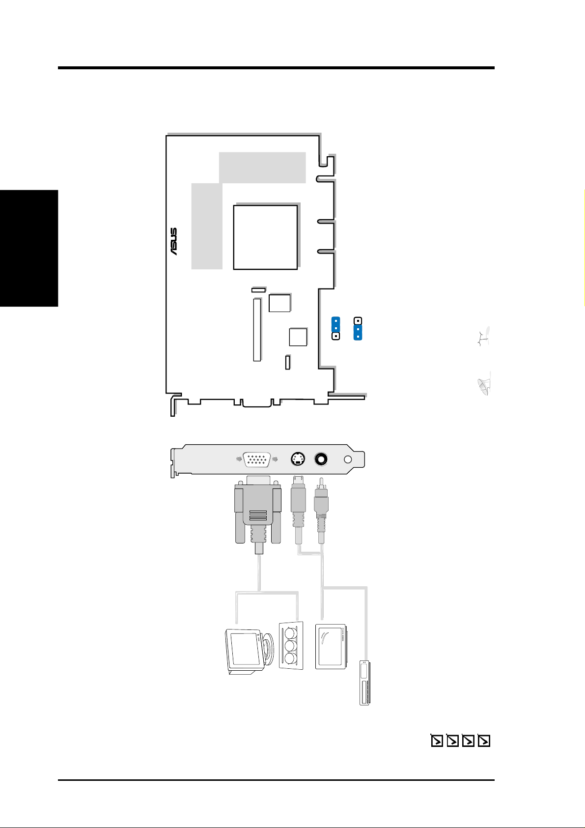
II. H/W Setup
VGA Output
S-Video Output
Composite (RCA) Output
VGA Monitor
output (15pin)
(standard)
composite/TV
output (RCA)
SVHS/TV output
(7pin)
Projector
123
123
NTSC
PAL
JP1
JP1
Use the same TV standard for all devices. For example,
if your TV uses the NTSC standard, then you should set
JP1 to “NTSC.”
Digital
PC to TV
Encoder
NVIDIA
TM
GeForce2 GTS
TM
GPU
(Graphics Processing Unit)
Chip with Fan
J1
Fan
Power
The VIP (Video Interface Port) Connector are used for third party add-on modules,
such as video capture cards or television tuners.
VGA
BIOS
®
32/64MB Frame Buffer (DDR)
DDR: Double Data Rate
VIP Connector A
V7700 / T
II. Hardware Setup
cannot be connected at the same time.
and
ASUS V7700 / T
64/32MB DDR Frame Buffer
Notes
• Use the same TV standard for all devices.
•
NOTE: V7700 / T 64MB DDR Frame Buffer model is shipped without a composite output connector
ASUS V7700 / T Graphics Card (PAL or NTSC)
ASUS VR-100G (optional)
This User’s Manual
ASUS V7700 Series Driver & Utility CD Disc
ASUS V7700 Series User’s Manual10
Item Checklist
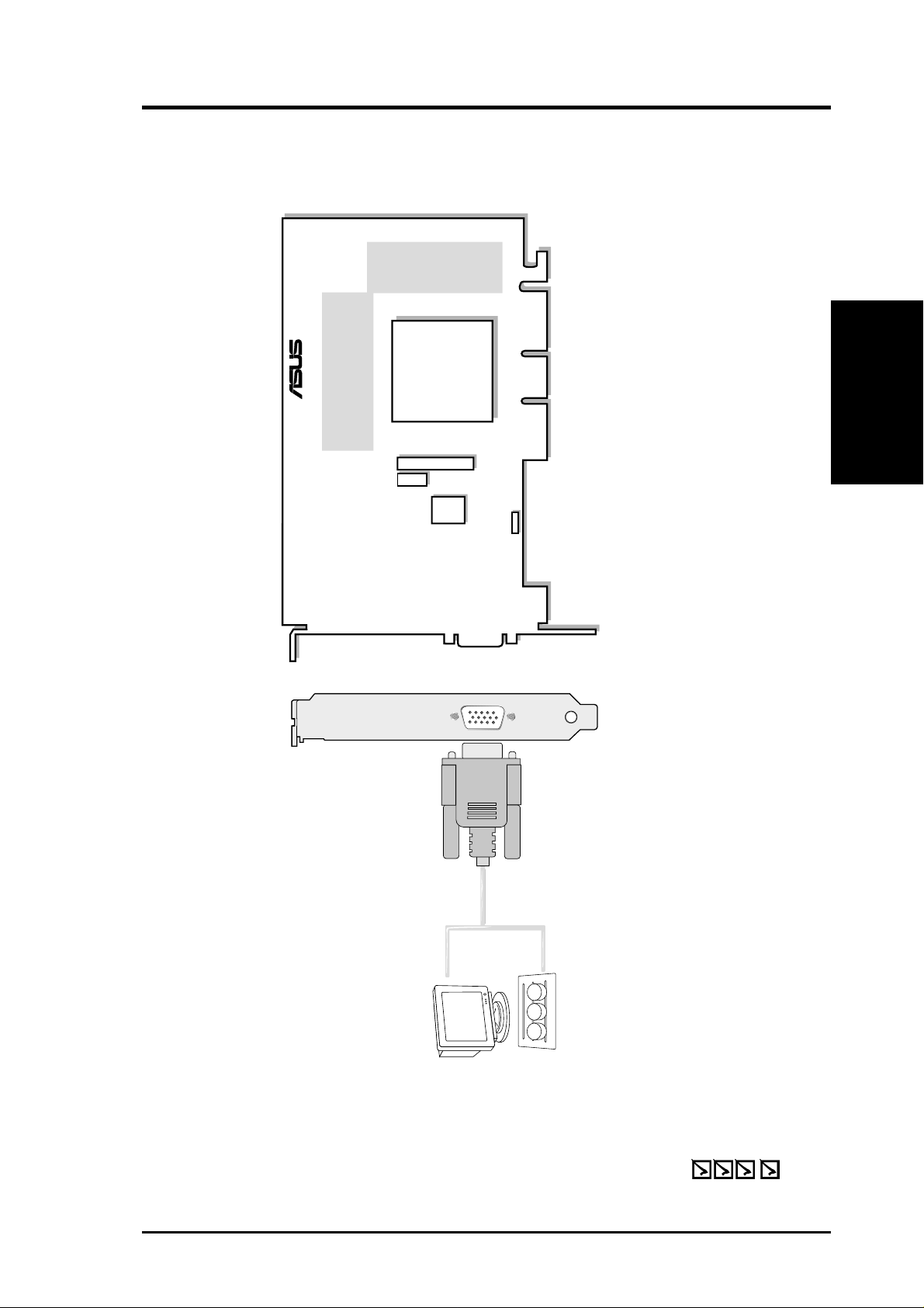
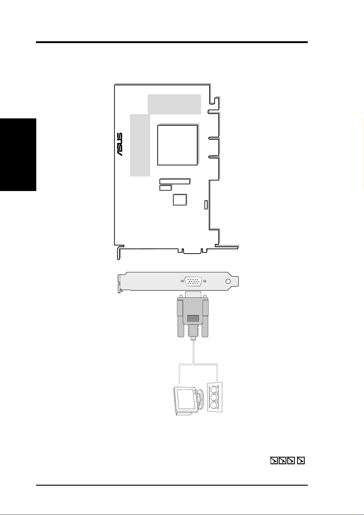
II. Hardware Setup
VGA Output
VGA Monitor
output (15pin)
(standard)
Projector
VGA
BIOS
TV-Out Module Connector
FAN_PWR
32/64MB Frame Buffer (DDR)
®
DDR: Double Data Rate
NVIDIA
TM
GeForce2 GTS
TM
GPU
(Graphics Processing Unit)
Chip with Fan
1
V7700 Pure
II. H/W Setup
64/32MB DDR Frame Buffer
ASUS V7700 (Pure VGA) Layout
ASUS V7700 Graphics Card
ASUS TV77 TV-Out Module (optional; see installation procedures later in this section)
This User’s Manual
ASUS V7700 Series Driver & Utility CD Disc
Item Checklist
11ASUS V7700 Series User’s Manual
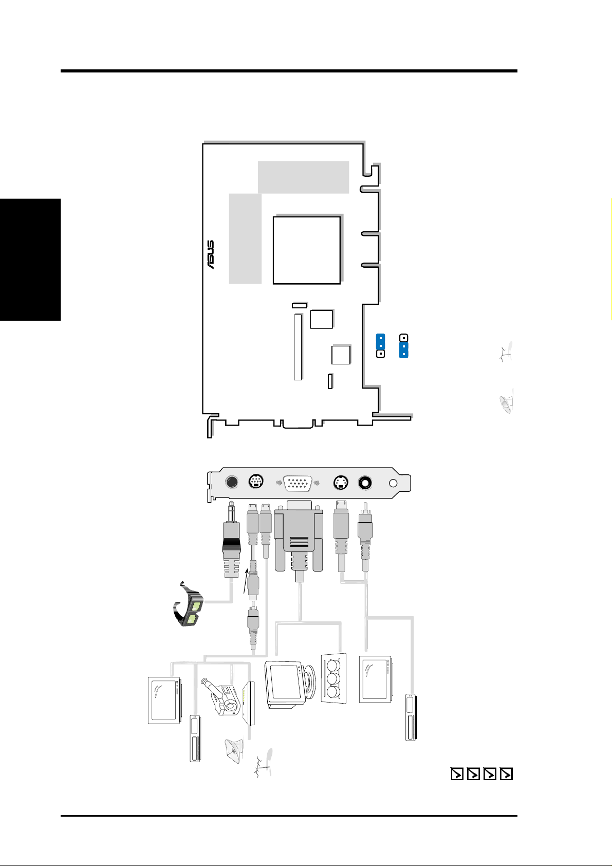
V7700Pro / Deluxe
Stereo Glasses Output
Video Input (ASUS Video) 7pin S compatible)
VGA Output
S-Video Output
Composite (RCA) Output
VGA Monitor
output (15pin)
(standard)
VR Glasses
Output
composite/TV
output (RCA)
CCD/camcorder
input/Tuner/
TV Box Input
(7pin)
SVHS/TV output
(7pin)
Projector
ASUS TV Box
CATV
Composite (RCA) Input
S-Video to Composite Cable
3D Glasses
(ASUS VR-100G)
®
123
123
NTSC
PAL
JP1
JP1
Use the same TV standard for all devices. For example,
if your TV uses the NTSC standard, then you should set
JP1 to “NTSC.”
Digital
PC to TV
Encoder
NVIDIA
TM
GeForce2 Pro
GPU
(Graphics Processing Unit)
Chip with Fan
J1
Fan
Power
The VIP (Video Interface Port) Connector are used for third party add-on modules,
such as video capture cards or television tuners.
VGA
BIOS
®
64MB Frame Buffer (DDR)
DDR: Double Data Rate
VIP Connector A
II. H/W Setup
II. Hardware Setup
cannot be connected at the same time.
64MB DDR Frame Buffer
ASUS V7700Pro Deluxe
and
Notes
• Use the same TV standard for all devices.
•
ASUS V7700 Series User’s Manual12
ASUS V7700 TVR Graphics Card (PAL or NTSC)
ASUS VR-100G
This User’s Manual
ASUS V7700 Series Driver & Utility CD Disc
Item Checklist

II. Hardware Setup
VGA Output
VGA
Monitor
output
(15pin)
(standard)
Projector
SVHS/
TV output
(7pin)
FAN_PWR
64MB Frame Buffer (DDR)
®
DDR: Double Data Rate
NVIDIA
TM
GeForce2 Pro
GPU
(Graphics Processing Unit)
Chip with Fan
V7700Pro / T
II. H/W Setup
ASUS V7700 Pro / T Layout
64MB DDR Frame Buffer
ASUS V7700 Pro / T Graphics Card
ASUS TV77 TV-Out Module
This User’s Manual
ASUS V7700 Series Driver & Utility CD Disc
Item Checklist
13ASUS V7700 Series User’s Manual

V7700Pro / Pure
VGA Output
VGA Monitor
output (15pin)
(standard)
Projector
VGA
BIOS
TV-Out Module Connector
FAN_PWR
64MB Frame Buffer (DDR)
®
DDR: Double Data Rate
NVIDIA
TM
GeForce2 Pro
GPU
(Graphics Processing Unit)
Chip with Fan
1
II. H/W Setup
II. Hardware Setup
64MB DDR Frame Buffer
ASUS V7700 Pro (Pure VGA) Layout
ASUS V7700 Pro Graphics Card
ASUS TV77 TV-Out Module (optional; see installation procedures later in this section)
This User’s Manual
ASUS V7700 Series Driver & Utility CD Disc
Item Checklist
ASUS V7700 Series User’s Manual14
II. Hardware Setup
VGA Output
S-Video Output
Composite (RCA) Output
VGA Monitor
output (15pin)
(standard)
composite/TV
output (RCA)
SVHS/TV output
(7pin)
Projector
123
123
NTSC
PAL
JP1
JP1
Use the same TV standard for all devices. For example,
if your TV uses the NTSC standard, then you should set
JP1 to “NTSC.”
Digital
PC to TV
Encoder
NVIDIA
TM
GeForce2 T2
TM
GPU
(Graphics Processing Unit)
Chip with Fan
J1
Fan
Power
The VIP (Video Interface Port) Connector are used for third party add-on modules,
such as video capture cards or television tuners.
VGA
BIOS
®
32/64MB Frame Buffer (DDR)
DDR: Double Data Rate
VIP Connector A
ASUS V7700 TI / T
64/32MB DDR Frame Buffer
V7700 TI / T
II. H/W Setup
cannot be connected at the same time.
and
Notes
• Use the same TV standard for all devices.
•
NOTE: V7700 / T 64MB DDR Frame Buffer model is shipped without a composite output connector
ASUS V7700 / T Graphics Card (PAL or NTSC)
ASUS VR-100G (optional)
This User’s Manual
ASUS V7700 Series Driver & Utility CD Disc
Item Checklist
15ASUS V7700 Series User’s Manual
VGA Output
VGA Monitor
output (15pin)
(standard)
Projector
VGA
BIOS
TV-Out Module Connector
FAN_PWR
32/64MB Frame Buffer (DDR)
®
DDR: Double Data Rate
NVIDIA
TM
GeForce2 TI
TM
GPU
(Graphics Processing Unit)
Chip with Fan
1
V7700 TI / Pure
II. H/W Setup
64/32MB DDR Frame Buffer
ASUS V7700 TI (Pure VGA) Layout
ASUS V7700 Graphics Card
ASUS TV77 TV-Out Module (optional; see installation procedures later in this section)
This User’s Manual
ASUS V7700 Series Driver & Utility CD Disc
Item Checklist
ASUS V7700 Series User’s Manual16

Stereo Glasses Output
Video Input (ASUS Video) 7pin S compatible)
VGA Output
S-Video Output
Composite (RCA) Output
VGA Monitor
output (15pin)
(standard)
VR Glasses
Output
composite/TV
output (RCA)
CCD/camcorder
input/Tuner/
TV Box Input
(7pin)
SVHS/TV output
(7pin)
Projector
ASUS TV Box
CATV
Composite (RCA) Input
S-Video to Composite Cable
3D Glasses
(ASUS VR-100G)
®
123
123
NTSC
PAL
JP1
JP1
Use the same TV standard for all devices. For example,
if your TV uses the NTSC standard, then you should set
JP1 to “NTSC.”
Digital
PC to TV
Encoder
NVIDIA
TM
GeForce2 TI
TM
GPU
(Graphics Processing Unit)
Chip with Fan
J1
Fan
Power
The VIP (Video Interface Port) Connector are used for third party add-on modules,
such as video capture cards or television tuners.
VGA
BIOS
®
64/32MB Frame Buffer (DDR)
DDR: Double Data Rate
VIP Connector A
II. H/W Setup
V7700 TI / Deluxe
cannot be connected at the same time.
64/32MB DDR Frame Buffer
ASUS V7700 TI Deluxe
and
Notes
• Use the same TV standard for all devices.
•
ASUS V7700 TVR Graphics Card (PAL or NTSC)
ASUS VR-100G
This User’s Manual
ASUS V7700 Series Driver & Utility CD Disc
Item Checklist
17ASUS V7700 Series User’s Manual
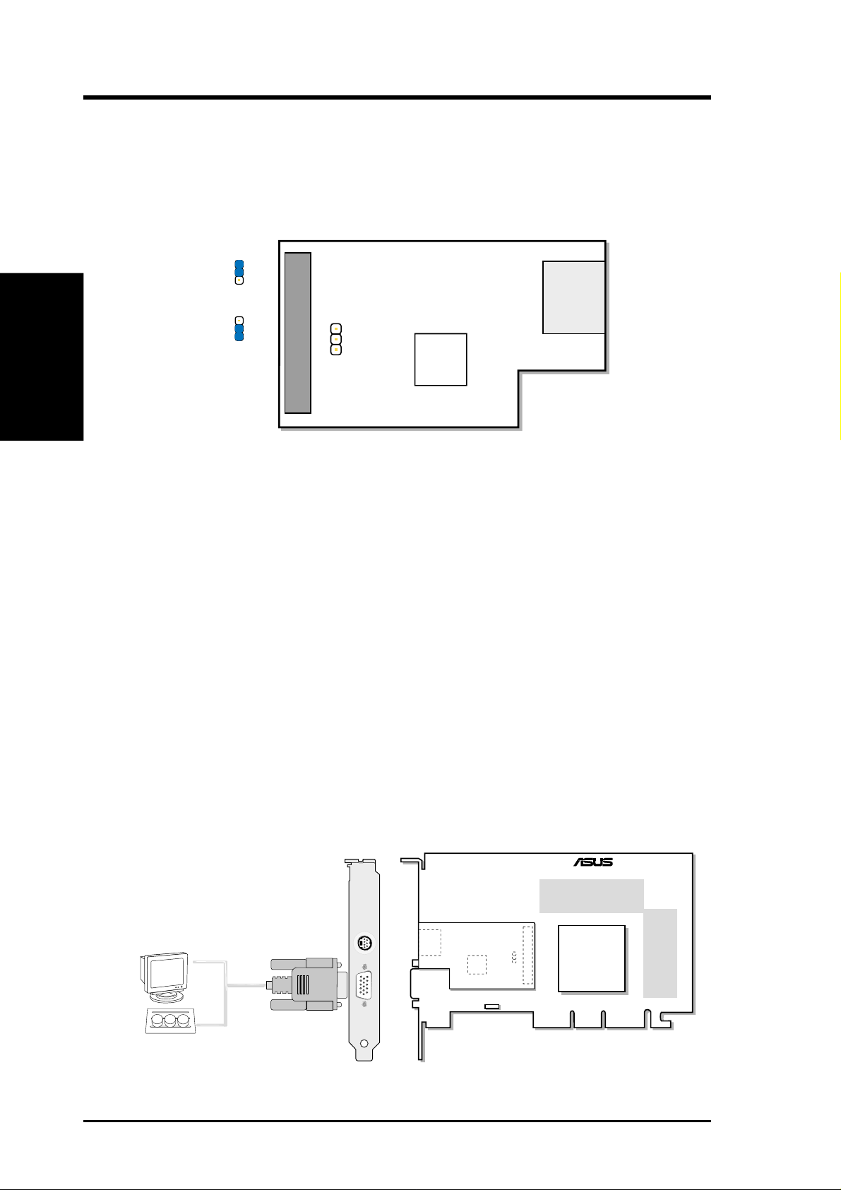
ASUS TV77 TV-Out Module (Optional)
The ASUS TV77 TV-Out Module lets you connect S-Video or TV devices to the ASUS
V7700 / ASUS V7700 Pro. See your dealer for more information on this module.
ASUS TV77 TV-Out Module Layout
II. H/W Setup
ASUS TV77
ASUS TV77 TV-Out Module Connection
When installed, the TV-Out Module’s components face the graphics card’s compo-
nents (as shown below).
J1
3
1
NTSC
J1
3
1
PAL
Use the same TV standard for all devices. For example, if your TV
uses the NTSC standard, then you should set J1 to “NTSC”.
TV-Out
Connector
J1
3
1
Digital
Video
Interface
S-Video/TV
Output
(7-pin)
IMPORTANT: Make sure that all electrical cords to your system are unplugged
before you install the TV77 TV-Out Module.
To install,
Position the TV77 TV-Out Module’s S-Video/TV Output toward the hole on
•
the V7700 / ASUS V7700 Pro card’s bracket and then,
• Position the TV77’s TV-Out Connector directly over the V7700 / ASUS V7700
Pro’s TV -Out Module Connector , making sure the pins are aligned with the V7700’s
module connector . Firmly but gently press the TV77 down into the connector . Make
sure that the TV77 is securely seated in the connector.
You are now ready to connect S-Video/TV devices to your card!
DDR: Double Data Rate
®
32/64MB Frame Buffer (DDR)
TM
NVIDIA
GeForce2 Pro
GPU
(Graphics Processing Unit)
Chip with Fan
Projector
VGA Output
VGA Monitor
output (15pin)
(standard)
FAN_PWR
ASUS V7700 Series User’s Manual18
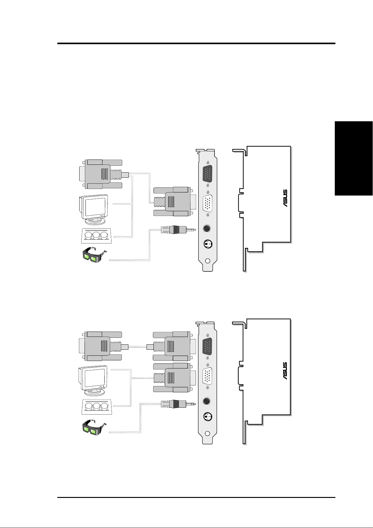
II. Hardware Setup
ASUS VR-100 Optional Upgrade Kit
The ASUS VR-100 Optional Upgrade Kit enables the ASUS VR-100G 3D Glasses
to be used with Pure models of the V7700 Series cards. See your dealer for more
information on the ASUS VR-100 Optional Upgrade Kit.
The monitor cable that came with your kit may be of the Y- or standard type. Connect your cable accordingly.
Y-Type Connection
To VGA Card’s Monitor Output
VGA Input
®
VGA Monitor
output (15pin)
(standard)
ASUS VR-100
II. H/W Setup
VGA Output
VR Glasses
Output
Projector
3D Glasses
(ASUS VR-100G)
Stereo Glasses Output
(Reserved)
ASUS VR-100
When using a Y-type cable, you do not need to connect the VGA Input of the VR-100 to your VGA
card’s monitor output (see diagram above).
Standard Connection
To VGA Card’s Monitor Output VGA Input
VGA Input
®
VGA Monitor
output (15pin)
(standard)
Projector
VGA Output
Stereo Glasses Output
VR Glasses
Output
(Reserved)
ASUS VR-100
3D Glasses
(ASUS VR-100G)
You must anchor the ASUS VR-100’s mounting bracket with a screw to a free ex-
pansion slot in your computer chassis.
19ASUS V7700 Series User’s Manual

NOTE: This graphics card series can only be installed in motherboards with an
AGP slot.
II. H/W Setup
Procedures
Installation Procedures
II. Hardware Setup
WARNING! Computer boards and components contain very delicate Integrated
Circuit (IC) chips. To protect the computer board and other components against
damage from static electricity, you must follow some precautions.
1. Make sure that you unplug your power supply when adding or removing
expansion cards or other system components. Failure to do so may cause
severe damage to both your motherboard and expansion cards.
2. Keep all components such as the host adapter in its antistatic bag until you
are ready to install it.
3. Use a grounded wrist strap before handling computer components. If you do
not have one, touch both of your hands to a safely grounded object or to a
metal object, such as the power supply case. Hold components by the edges
and try not to touch the IC chips, leads, or circuitry.
4. Place components on a grounded antistatic pad or on the bag that came with the
component whenever the components are separated from the system.
New Systems
1. Unplug all electrical cords on your computer.
2. Remove the system unit cover.
3. Locate the AGP bus expansion slot. Make sure this slot is unobstructed.
4. Remove the corresponding expansion slot cover from the computer chassis.
5. Ground yourself to an antistatic mat or other grounded source .
6. Pick up the board (still in its sleeve) by grasping the edge bracket with one hand
and then remove the plastic sleeve.
7. Position the card directly over the AGP slot and insert one end of the board in
the slot first. Firmly but gently press the bus connector on the bottom of the card
down into the slot. Be sure the metal contacts on the bottom of the host adapter
are securely seated in the slot.
8. Anchor the board’s mounting bracket to the computer chassis using the screw
from the slot cover that you set aside previously.
9. Replace the cover on the system unit.
10. Connect your analog monitor’s 15-pin VGA connector to the card and fasten
the retaining screws (if any).
11. Connect other cables and devices if available -You are now ready to install the
software drivers and utilities.
Systems with Existing VGA Card
1. Change your display driver to Standard VGA.
2. Shut down your computer and unplug all electrical cords.
3. Replace the existing VGA card with your graphics card.
4. Restart your computer.
5. Install the ASUS V7700 series display driver.
ASUS V7700 Series User’s Manual20

III. Software Setup
Operating System Requirements
NOTE: T his graphics card requires a motherboard with an AGP slot.
Windows 98
Windows 98 supports full Direct3D and AGP features. If you are still using the beta
version of W indows 98 and you want to fully take advantage the Direct3D and AGP
features, you must upgrade it to the release version before installing the AGP display driver.
Windows 98 includes VGARTD for the major chipsets but it is recommended that
you install VGARTD from the ASUS V7700 Series CD to make sure that you have
the latest version of VGARTD (see III. Software Setup | Install GART Driver).
NOTES
• VGARTD stands for V irtual Graphics Address Remapping T able Driver, which
is necessary to use the DIME feature of AGP. DIME means Direct Memory
Execute, which is accessed directly by most AGP chips (when VGARTD is
installed) for complex texture-mapping operations.
• For other notes or release information, see the README files in the installa-
tion CD disc.
• This Manual assumes that your CD-ROM disc drive is drive D: and that
Windows is in C:\WINDOWS. Replace either with the actual location, if
necessary.
Requirements
III. S/W Setup
21ASUS V7700 Series User’s Manual
Display Driver Installation
You can use one of the recommended methods to install the display drivers for your
graphics card, depending on your operating system.
NOTE: The screen displays in this manual may not reflect exactly the screen contents displayed on your screen. The contents of the support CD are subject to change
at any time without notice.
Windows 98
Method 2 and Method 3 will not install the appropriate AGP GART driver if your
motherboard does not use the Intel AGPset. Installing the AGP GART driver will
ensure that the AGPset’s AGP functions are available. Method 2 and Method 3 will
not install also the DirectX runtime libraries. DirectX must be installed so that your
video player can take advantage of hardware acceleration. See III. Software Setup
| Install GART Driver and III. Software Setup | Install DirectX later in this manual
Display Drivers
III. S/W Setup
for the setup steps.
III. Software Setup
Method 1: ASUS Quick Setup Program
NOTE: See III. Software Setup | Drivers | Install Display Driver for more information.
1. Start Windows.
2. Switch display to Windows’ Standard Display Adapter (VGA) mode and then
restart Windows.
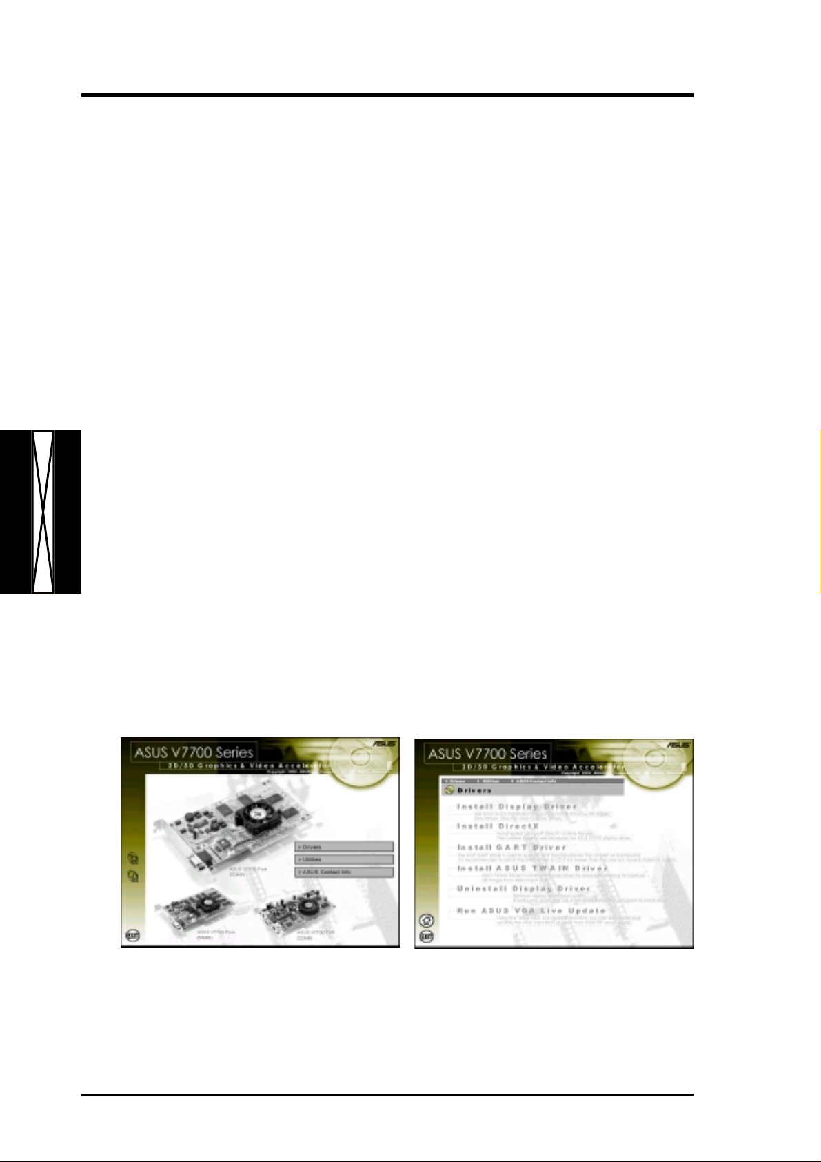
3. Insert the CD installation disc into your CD-ROM drive.
4. The Install Shell appears. Click Drivers and then click Install Display Driver on
the Drivers dialog box.
5. Follow the onscreen instructions to complete the setup.
6. When Setup has finished installing all the necessary files on your computer, it
will prompt you to restart your computer. Click Yes... and then Finish to restart
your computer and to complete Setup.
ASUS V7700 Series User’s Manual22
III. Software Setup
Method 2: Display Property Page
1. Start Windows.
2. Switch display to Windows’ Standard Display Adapter (VGA) mode and then
restart Windows.
3. Right-click the Windows desktop and click Properties.
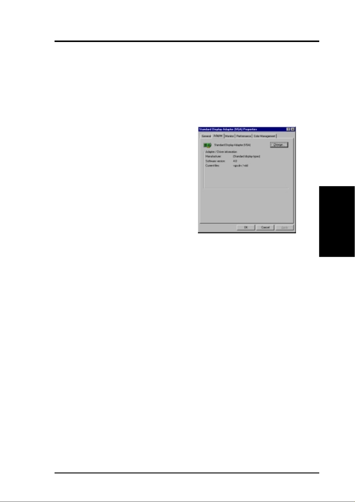
4. Click the Settings tab and then click Advanced. The Standard Display Adapter
(VGA) Properties dialog box appears.
5. Click Change on the Adapter tab. The Up-
date Device Driver Wizard dialog box appears. Click Next, click Display a list of all
the drivers... and then click Next.
6. Click Show all hardware and then click
Have Disk....When the Install From Disk
dialog box appears, type the location of the
ASUSNV9X.INF file and then proceed to step
9. Otherwise, proceed to the next step.
7. Click Browse to search the CD-ROM drive.
In the Drives box of the Open dialog box,
select your CD-ROM drive and then click
OK.
8. In the Folders box, double-click the
in the File name box.
9. Click OK . A list of video cards appears. Select your VGA card type for your operating
system and then click OK.
10. The Update Driver Warning box appears. Click Yes to confirm the set-
ting up of the ASUS enhanced display drivers and then follow the onscreen instructions to start the setup.
11. Setup will prompt you when it has finished installing all the necessary
files on your computer. Click Finish to close Setup.
12. When you are returned to the Standard Display Adapter (VGA) Prop-
erties box, click Close. The Display Properties box appears. Click Close.
13. The system will prompt you to restart your computer. Click Yes to restart
your computer and to complete Setup.
WIN9x folder and then select ASUSNV9X.INF
III. S/W Setup
Display Drivers
23ASUS V7700 Series User’s Manual
Method 3: Plug and Play
NOTE: Before proceeding with these steps, replace first your old VGA card with
an ASUS V7700 series graphics card.
1. Start Windows.
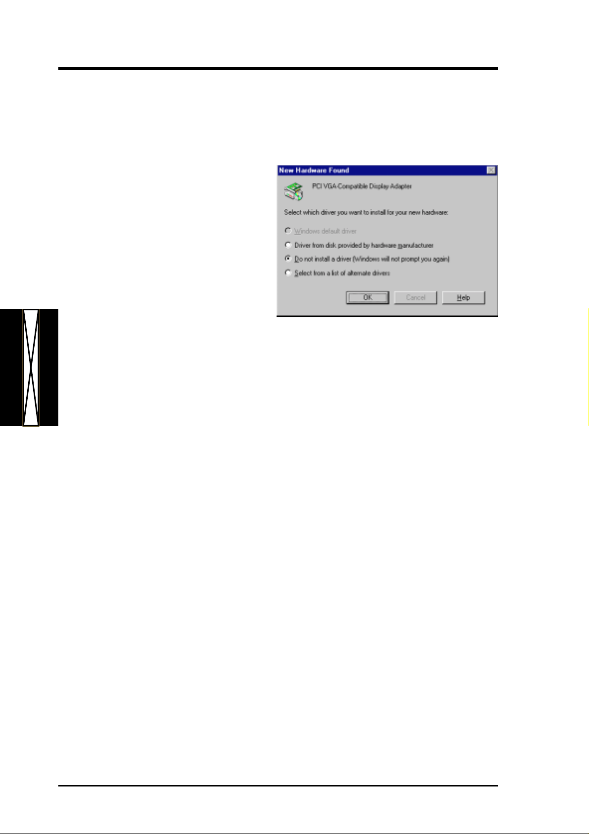
2. When Windows detects your ASUS
V7700 series graphics card, the
New Hardware Found dialog box
appears.
3. Click Driver from disk provided
by hardware manufacturer.
4. When Setup prompts you for the
Display Drivers
III. S/W Setup
location of the driver, typ e
to direct Setup to the INF file and then click Finish to install the driver .
III. Software Setup
D:\WIN9x
5. When Setup has finished installing all the necessary files on your computer, it
will prompt you to restart your computer . Click Yes to restart your computer and
to complete Setup.
ASUS V7700 Series User’s Manual24
III. Software Setup
Windows 2000
Method 1: ASUS Quick Setup Program
1. Start Windows.
2. When Windows detects your ASUS
graphics card, the Found New Hard-
ware Wizard dialog box appears.
3. Click Cancel to enter the Windows
desktop.
4. Insert the CD installation disc into
your CD-ROM drive.
5. The ASUS Windows 2000 Install
Shell appears. Click Drivers and then click Install Display Driver on the Driver
dialog box.
6. Follow the onscreen instructions to complete the setup.
7. When Setup has finished installing all the necessary files on your computer, it
will prompt you to restart your computer . Click Yes to restart your computer and
to complete Setup
III. S/W Setup
Display Drivers
25ASUS V7700 Series User’s Manual

Method 2: Plug and Play
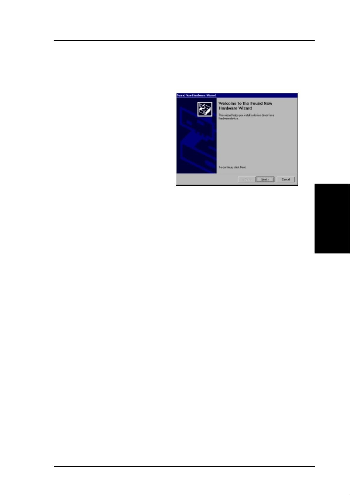
1. Start Windows.
2. When W indows detects your ASUS
graphics card, the Found New
Hardware Wizard dialog box appears.
3. Click Next.
4. When the next Found New Hard-
Display Drivers
III. S/W Setup
ware Wizard dialog box appears,
select Search for a suitable driver
for my device (recommended) and
then click Next..
III. Software Setup
5. Insert the CD installation disc into
your CD-ROM drive to bring up the
Locate Driver Files item of the
Found New Hardware W izard dia-
log box.
6. Check CD-ROM drives, uncheck
all other options and then click Next
to search for the drivers of your
graphics card.
ASUS V7700 Series User’s Manual26
III. Software Setup
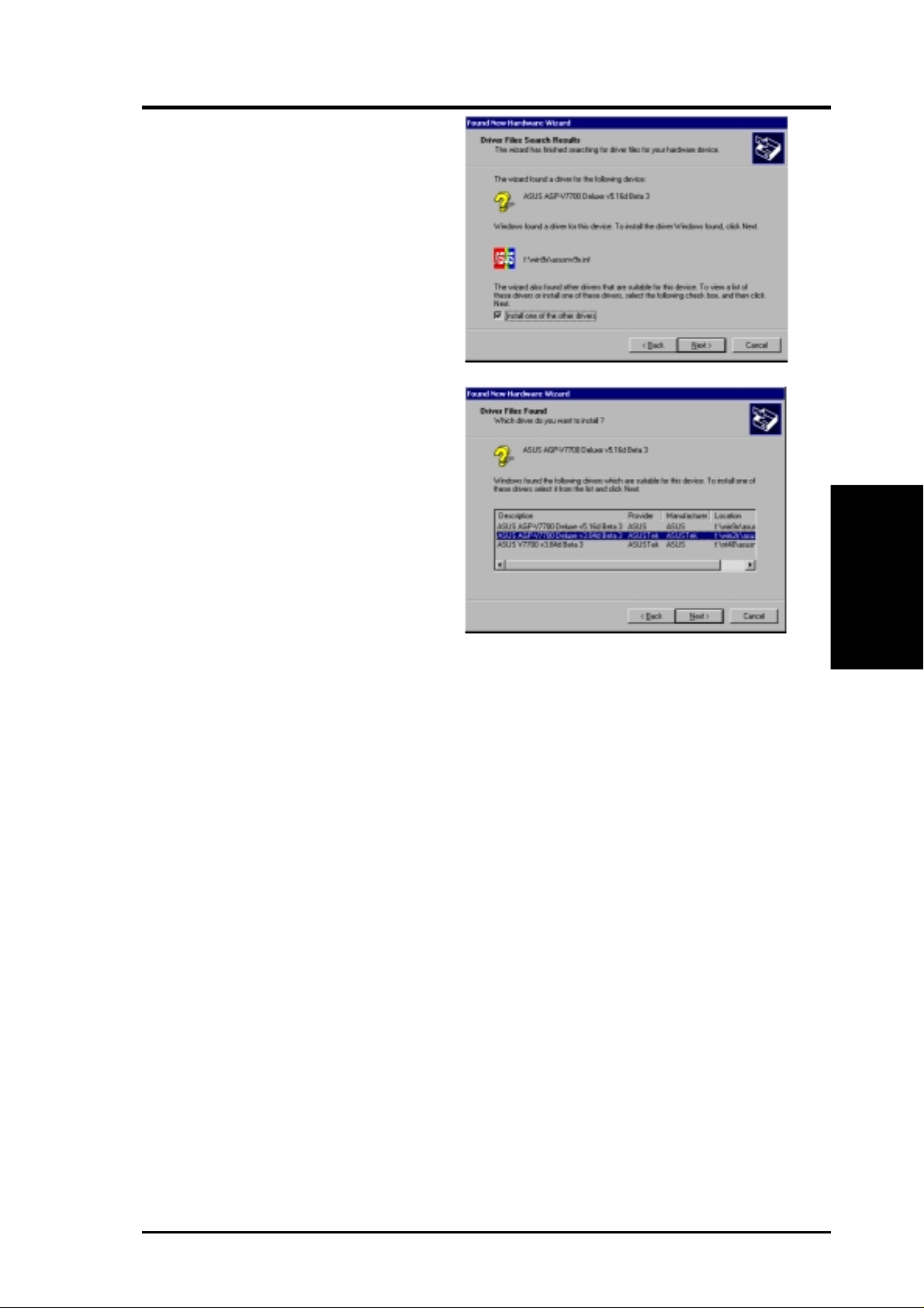
7. When the wizard has finished
searching for driver files for your
graphics card, select Install one of
the other drivers and then click
Next from the Driver Files Search
Results item of the Found New
Hardware Wizard dialog box.
8. When prompted to select the display
driver to install in your system, select the one that is located in the
D:\WIN2K and then click Next.
9. Follow the onscreen instructions to complete the setup.
10. When Setup has finished installing all the necessary files on your computer, it
will prompt you to restart your computer.
Click OK to restart your computer and to complete Setup.
III. S/W Setup
Display Drivers
27ASUS V7700 Series User’s Manual

Windows NT 4.0
Method 1: Display Property Page
W ARNING! Before installing the display driver in Windows NT 4.0, make sure that
you have installed Windows NT 4.0 Service Pack 3 or later, to take full advantage of the AGP features of your card. (You may download service packs at
http://www.microsoft.com/ntworkstation/downloads.)
NOTE: The following steps assume your CD-ROM drive letter is D.
1. Start Windows NT , switch display properties to VGA mode (16 colors, 640 x 480
pixels), then restart your computer to make the change.
2. After your computer restarts, right-click the desktop and click Properties.
Display Drivers
III. S/W Setup
3. Click the Settings tab.
III. Software Setup
4. Select Change Display Type.
5. Select Adapter Type and click Change.
6. Click Have Disk.
7. Insert the CD installation disc.
8. Type D:\NT40 or click Browse to select the path of the display driver for Win-
dows NT. Click OK.
9. Select ASUS V7700 and then click OK.
10. Windows NT will once again prompt for confirmation. All appropriate files are
then copied to the hard disk. When all files are copied, go back to the Display
Properties box by clicking Close. Click Apply.
11. The System Settings Change dialog box is displayed. Click
12. Windows NT will restart with the default settings. The Display applet will appear to allow for mode selection.
Yes to restart W indows.
ASUS V7700 Series User’s Manual28
III. Software Setup
Drivers
NOTES: 1) The screen displays in this manual may not reflect exactly the screen
contents displayed on your screen. The contents of the support CD
are subject to change at any time without notice.
2) Unless otherwise indicated, the procedures under Drivers apply
to all the operating systems supported, namely , W indows 98, Windows 2000, and Windows NT 4.0.
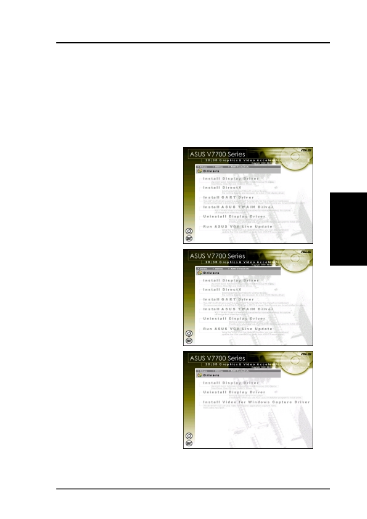
Install Display Driver
1. Insert the CD installation disc into
your CD-ROM drive or double click
the CD drive icon in My Computer
to bring up the autorun screen or run
Setup.exe in the root directory of
your CD-ROM drive.
Click Drivers.
2. Windows 98: The Drivers box appears. Click Install Display Driver
to install all the drivers and utilities
into your computer . Setup will install
the drivers in the following order:
Display Driver (Direct3D and
OpenGL Drivers), DirectX runtime
libraries, and VGART driver. Just
follow the on-screen instructions to
complete the installation.
Windows 2000: Setup will only
copy the display drivers.
Windows NT 4.0:
appear. Follow the instructions to
install the display driver. You may
refer to the installation procedures
earlier in III. Software Setup | Win-
dows NT 4.0 | Method 1: Display
Property Page.
SETUPNT.TXT will
Drivers
III. S/W Setup
If you prefer to install the drivers individually , follow the steps on the following pages.
29ASUS V7700 Series User’s Manual
III. S/W Setup
Drivers
III. Software Setup
Install DirectX
Windows 98 Only
Microsoft DirectX allows 3D hardware acceleration support in Windows 98. For
Software MPEG support in Windows 98, you must first install Microsoft DirectX,
and then an MPEG-compliant video player.
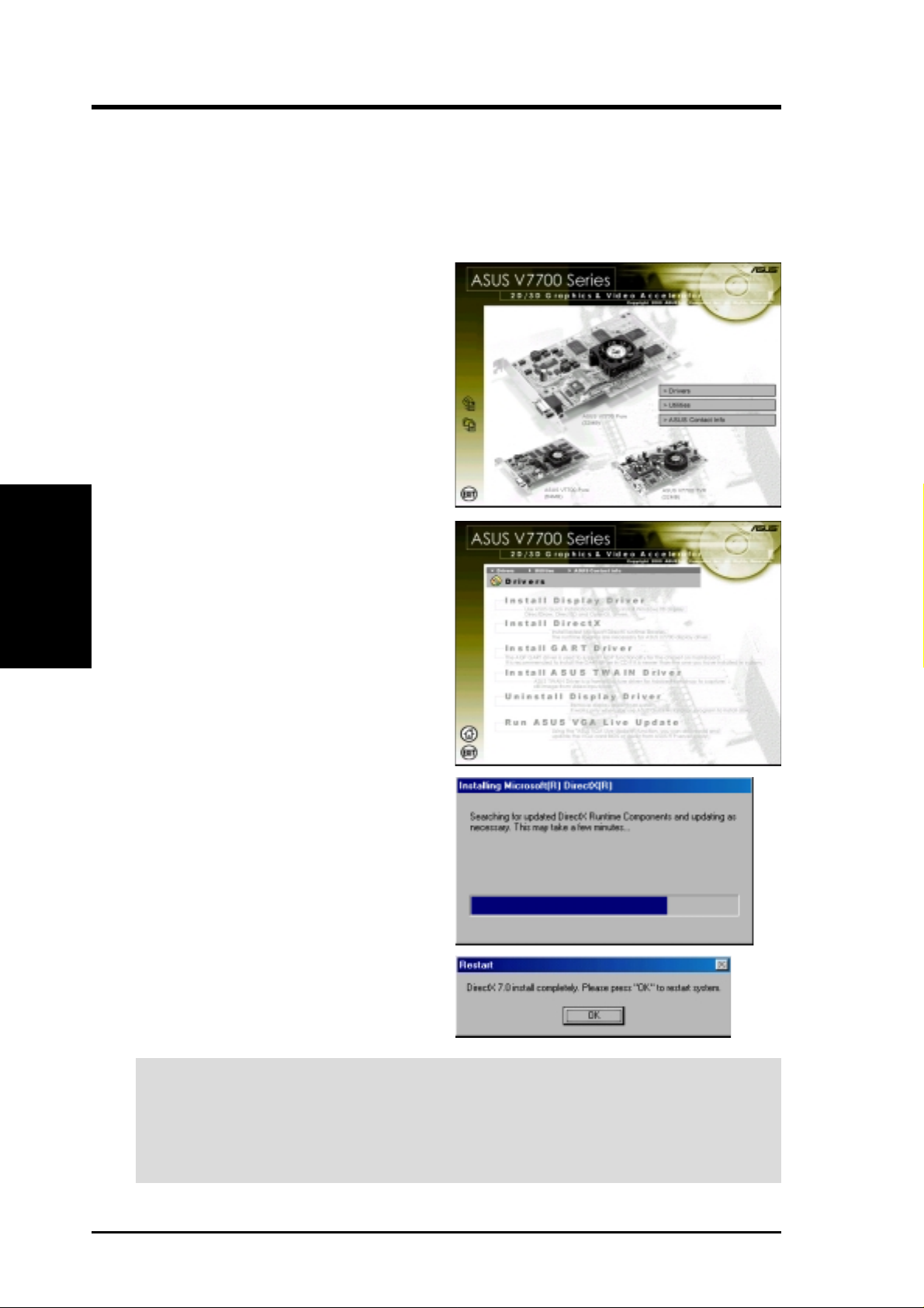
1. Insert the CD installation disc into
your CD-ROM drive or double click
the CD drive icon in My Computer
to bring up the autorun screen or run
Setup.exe in the root directory of
your CD-ROM drive.
Click Drivers.
2. The Drivers box appears. Click In-
stall DirectX to select the DirectX
version you want to install.
3. The installation program will automatically install the DirectX 7
runtime libraries into your system.
4. Setup will prompt when it has finished copying all the files to your
computer . Click OK to finish the installation.
WARNING! Some games written for older DirectX versions may not work prop-
erly under DirectX 7. Make sure that your applications or games support DirectX
7 before installing the DirectX 7 runtime libraries. DirectX 7 currently cannot be
uninstalled by regular means, such as outlined in III. Software Setup | Uninstall
Display Driver.
ASUS V7700 Series User’s Manual30
 Loading...