How it Works
Log In / Sign Up
Buy Points
How it Works
FAQ
Contact Us
Questions and Suggestions
Users
ASUS
Loading...
R
RS520-E6RS8
4
RS520-E8-RS12-E
8
RS520-E8-RS8
8
RS520-E8-RS8 V2
RS520-E9
RS520-E9-RS12-E
4
RS520-E9-RS8
4
RS520-X5/PS8
3
RS540-E8-RS36-ECP
3
RS540-E9-RS36-E
3
RS620SA-E10-RS12
RS700A-E11-RS12U
RS700A-E9-RS12
4
RS700A-E9-RS12V2
3
RS700A-E9-RS4
4
RS700A-E9-RS4V2
3
RS700DA-E6 PS4
2
RS700D-E6PS8
4
RS700D-E6/PS8 ASWM ENTERPRISE
RS700-E6/ERS4
3
RS700-E6/ERS4 ASWM ENTERPRISE
RS700-E6RS4
3
RS700-E7-RS12
RS700-E7/RS4
6
RS700-E7/RS4-C
4
RS700-E7/RS8
6
RS700-E8-RS4
9
RS700-E8-RS4 V2
2
RS700-E8-RS8
8
RS700-E9-RS12
5
RS700-E9-RS4
5
RS700-X7/PS4
5
RS702D-E6PS8
RS704DA-E6/PS4
2
RS704D-E6/PS8
2
RS720A-E11-RS24U
RS720A-E9-RS12V2
3
RS720A-E9-RS24-E
2
RS720A-E9-RS24V2
2
RS720-E6RS12
2
RS720-E6/RS12 ASWM ENTERPRISE
RS720-E7/RS12
3
RS720-E7-RS12-E
6
RS720-E7-RS24-EG
2
RS720-E8-RS12-X
RS720-E8-RS24-E
2
RS720-E8-RS24-ECP
3
RS720-E9-RS12-E
4
RS720-E9-RS24-E
3
RS720-E9-RS24-U
3
RS720-E9-RS8
4
RS720-E9-RS8-G
4
RS720QA-E6/RS12
2
RS720Q-E6 RS12
RS720Q-E6/RS12 ASWM ENTERPRISE
RS720Q-E7
RS720Q-E7/RS12
3
RS720Q-E8-RS12
7
RS720Q-E8-RS8-P
2
RS720Q-E9-RS24-S
2
RS720Q-E9-RS8
3
RS720Q-E9-RS8-S
4
RS720X7RS8
5
RS724QA-E6RS12
2
RS724Q-E6/RS12
RS724Q-E7/RS12
5
RS726Q-E7
RS726QE7RS12
5
RS740-E7-RS24-EG
3
RS920A-E6-RS8
2
RS920-E7-RS8
4
RS924A-E6-RS8
2
RS926-E7-RS8
5
RSS00A-E9-PS4
RT-3200R
RT-3200W
RT-AC1200
21
RT-AC1200E
RT-AC1200G
23
RT-AC1200GE
2
RT-AC1200G PLUS
4
RT-AC1200GU
3
RT-AC1200L
RT-AC1300G
RT-AC1300G PLUS
3
RT-AC1300UHP
24
RT-AC1500UHP
2
RT-AC1750
RT-AC1750U
2
RT-AC1900
2
RT-AC1900P
4
RT-AC1900U
21
RT-AC2400
16
RT-AC2600
2
RT-AC2900
24
RT-AC3100
5
RT-AC3200
25
RT-AC51
RT-AC51U+
17
RT-AC52
Loading...
Loading...
Nothing found
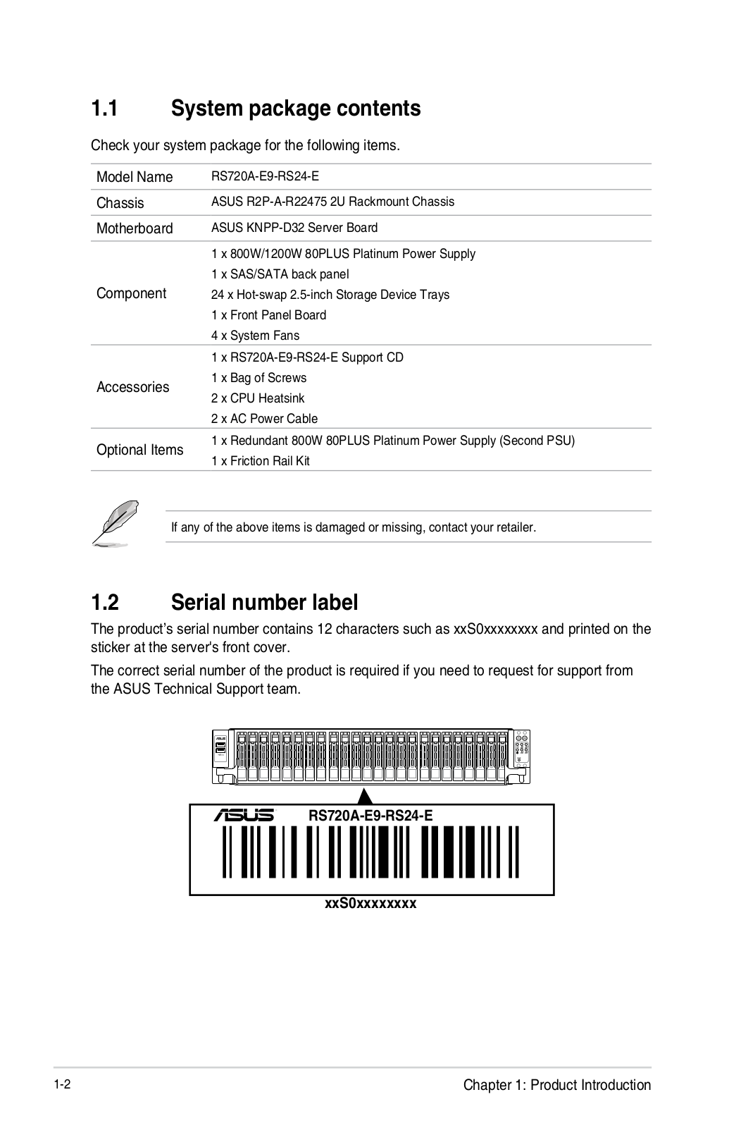
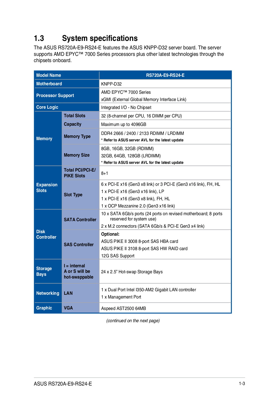
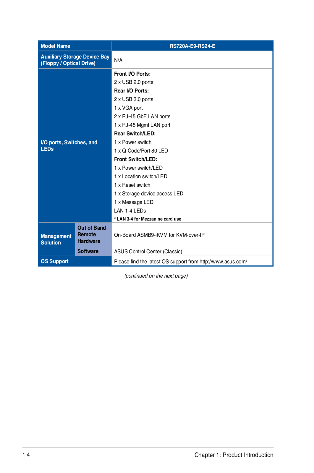
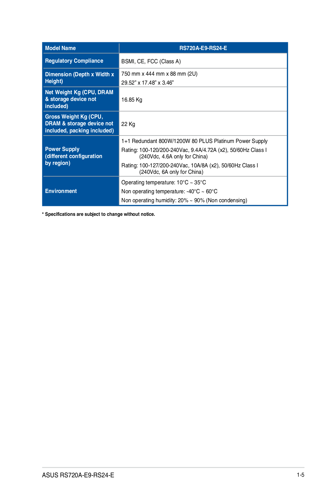
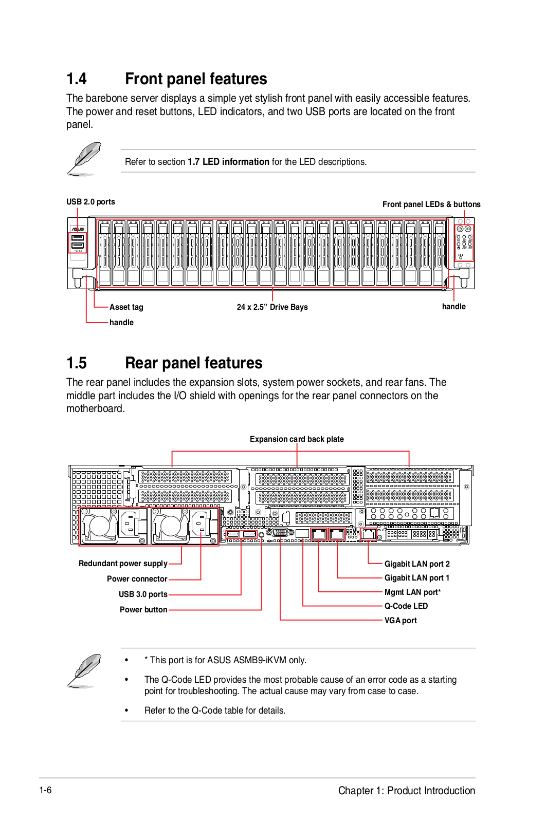
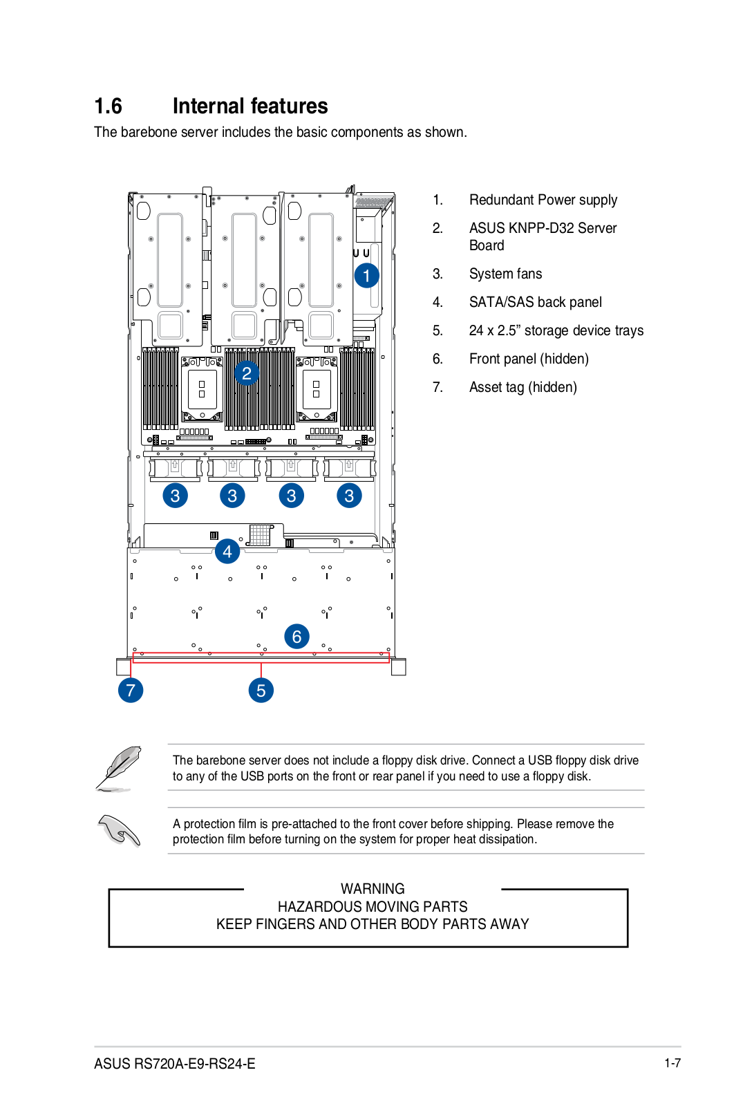
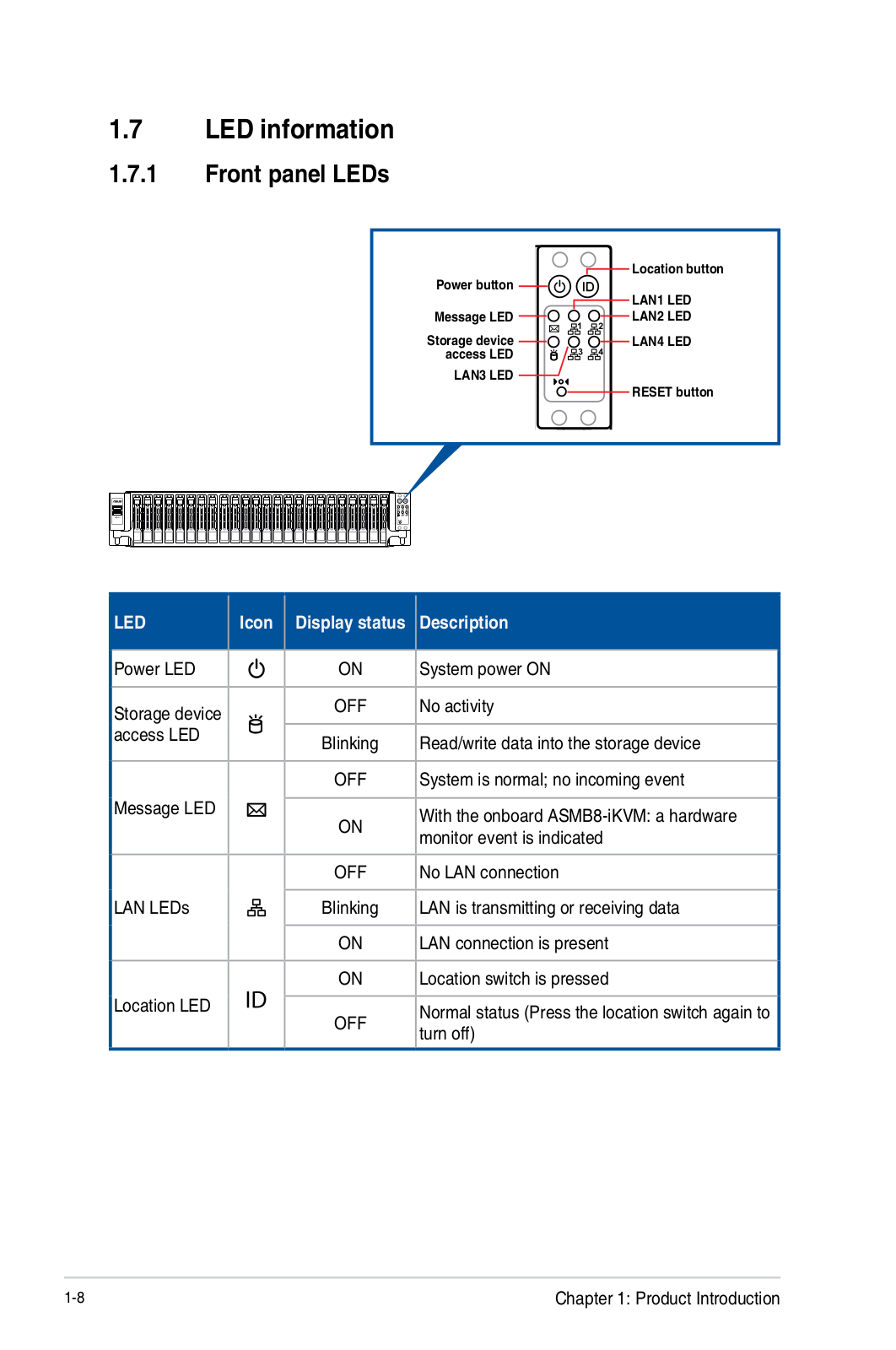
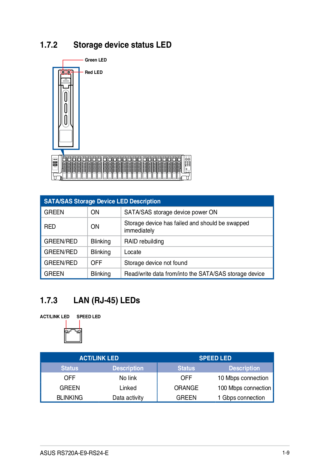
RS720A-E9-RS24-E
Service Manual
162 pgs
14.37 Mb
0
User’s Manual [zh]
158 pgs
13.48 Mb
0
Table of contents
Loading...
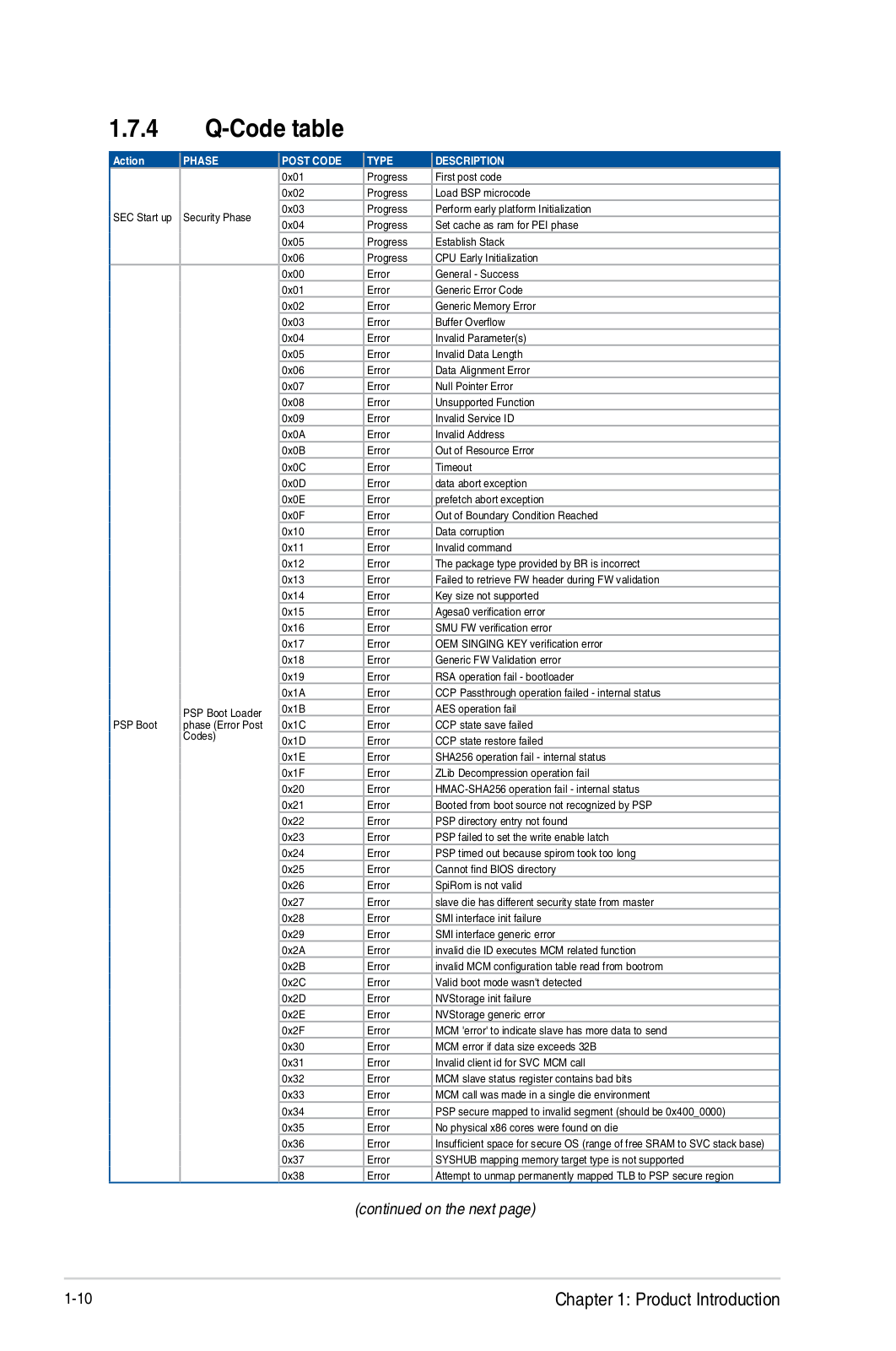
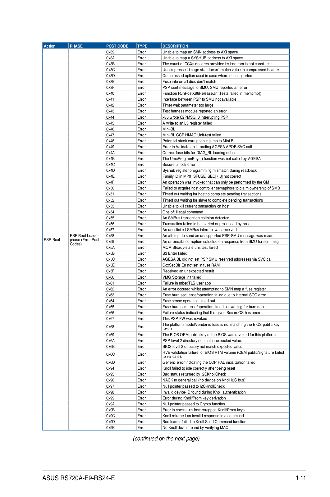
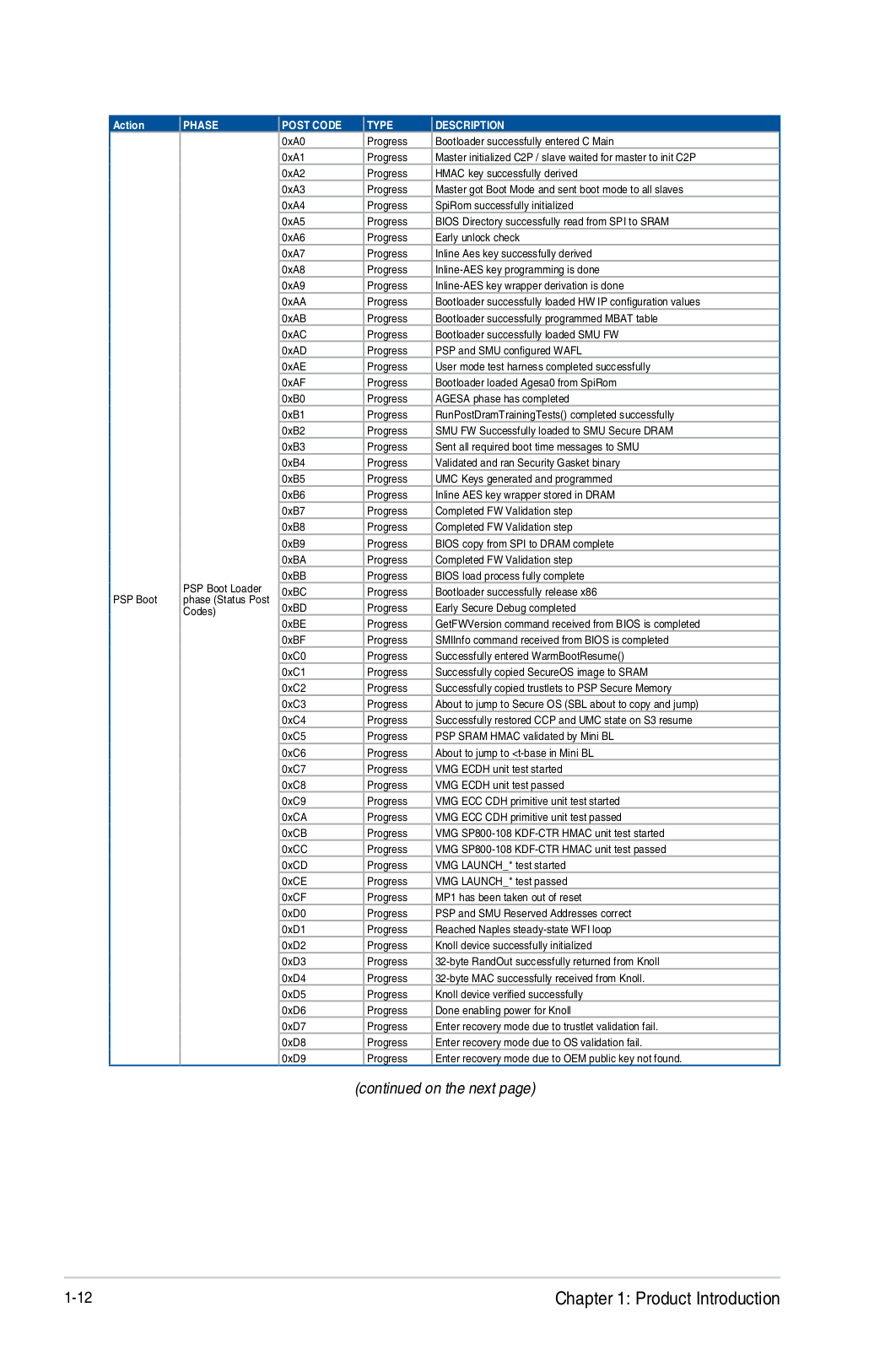
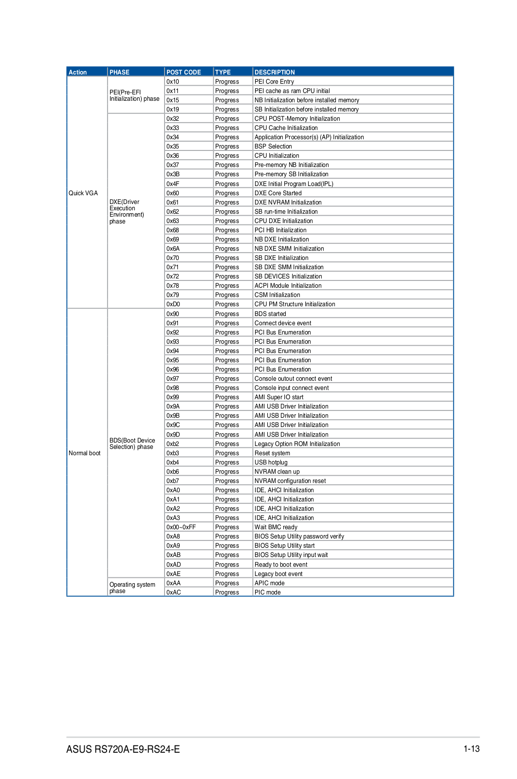
ASUS RS720A-E9-RS24E Service Manual
...
ASUS Service Manual
Download
Specifications and Main Features
Frequently Asked Questions
User Manual
Download
Loading...
+
132
hidden pages
Unhide
You need points to download manuals.
1 point = 1 manual.
You can buy points or you can get point for every manual you upload.
Buy points
Upload your manuals
 Loading...