

Page 1

RS720A-E11-RS24U
2U Rackmount Server
User Guide
Page 2

E17416
First Edition
March 2021
Copyright © 2021 ASUSTeK COMPUTER INC. All Rights Reserved.
No part of this manual, including the products and software described in it, may be reproduced, transmitted,
transcribed, stored in a retrieval system, or translated into any language in any form or by any means,
except documentation kept by the purchaser for backup purposes, without the express written permission
of ASUSTeK COMPUTER INC. (“ASUS”).
ASUS provides this manual “as is” without warranty of any kind, either express or implied, including but not
limited to the implied warranties or conditions of merchantability or fitness for a particular purpose. In no
event shall ASUS, its directors, officers, employees, or agents be liable for any indirect, special, incidental,
or consequential damages (including damages for loss of profits, loss of business, loss of use or data,
interruption of business and the like), even if ASUS has been advised of the possibility of such damages
arising from any defect or error in this manual or product.
Specifications and information contained in this manual are furnished for informational use only, and are
subject to change at any time without notice, and should not be construed as a commitment by ASUS.
ASUS assumes no responsibility or liability for any errors or inaccuracies that may appear in this manual,
including the products and software described in it.
Product warranty or service will not be extended if: (1) the product is repaired, modified or altered, unless
such repair, modification of alteration is authorized in writing by ASUS; or (2) the serial number of the
product is defaced or missing.
Products and corporate names appearing in this manual may or may not be registered trademarks or
copyrights of their respective companies, and are used only for identification or explanation and to the
owners’ benefit, without intent to infringe.
ii
Page 3

Contents
Safety information ..................................................................................................... vii
About this guide ....................................................................................................... viii
Chapter 1: Product Introduction
1.1 System package contents ......................................................................... 1-2
1.2 Serial number label .................................................................................... 1-2
1.3 System specifications ...............................................................................1-3
1.4 Front panel features ...................................................................................1-6
1.5 Rear panel features .................................................................................... 1-6
1.6 Internal features ......................................................................................... 1-7
1.7 LED information ......................................................................................... 1-9
1.7.1 Front panel LEDs ........................................................................1-9
1.7.2 Storage device status LED........................................................1-10
1.7.3 LAN (RJ-45) LEDs ....................................................................1-11
1.7.4 Q-Code table .............................................................................1-12
Chapter 2: Hardware Information
2.1 Chassis cover ............................................................................................. 2-2
2.2 Air ducts......................................................................................................2-4
2.3 Central Processing Unit (CPU) .................................................................2-7
2.3.1 Installing the CPU and heatsink ..................................................2-7
2.4 System memory .......................................................................................2-10
2.4.1 Overview ................................................................................... 2-10
2.4.2 Memory Configurations .............................................................2-11
2.4.3 Installing a DIMM on a single clip DIMM socket........................2-12
2.4.4 Removing a DIMM ....................................................................2-12
2.5 Storage devices........................................................................................2-13
iii
Page 4

Contents
2.6 Expansion slot ..........................................................................................2-15
2.6.1 Installing an expansion card to riser card bracket 1 .................. 2-16
2.6.2 Installing an expansion card to riser card bracket 2 .................. 2-19
2.6.3 Installing an expansion card to riser card bracket 3 .................. 2-22
2.6.4 Installing an expansion card to riser card bracket 4 .................. 2-25
2.6.5 Installing an OCP 3.0 slot baseboard and
OCP 3.0 card to the riser card bracket...................................... 2-28
2.6.6 Installing an ethernet expansion card to the
riser card bracket ...................................................................... 2-32
2.6.7 Installing GPU cards (on selected models) ............................... 2-33
2.6.8 Installing an ASUS PIKE II card ................................................2-43
2.6.9 Installing M.2 (NGFF) cards ......................................................2-47
2.6.10 Configuring an expansion card ................................................. 2-48
2.7 Cable connections ................................................................................... 2-49
2.8 SATA/SAS backplane cabling ................................................................. 2-50
2.9 Removable/optional components ...........................................................2-52
2.9.1 System fans ..............................................................................2-52
2.9.2 Redundant power supply module..............................................2-56
Chapter 3: Installation Options
3.1 Tool-less Friction Rail Kit .......................................................................... 3-2
3.2 Installing the tool-less rack rail ................................................................3-3
3.3 Rail kit dimensions ....................................................................................3-5
3.4 Cable management arm
(optional for 1200 mm rack rails) .............................................................. 3-6
3.4.1 Attaching the cable management arm ........................................3-6
Chapter 4: Motherboard Information
4.1 Motherboard layout ....................................................................................4-2
4.2 Jumpers ...................................................................................................... 4-4
4.3 Internal LEDs .............................................................................................. 4-9
4.4 Internal connectors .................................................................................. 4-11
iv
Page 5

Contents
Chapter 5: BIOS Setup
5.1 Managing and updating your BIOS .......................................................... 5-2
5.1.1 ASUS CrashFree BIOS 3 utility...................................................5-2
5.1.2 ASUS EZ Flash Utility .................................................................5-3
5.1.3 BUPDATER utility .......................................................................5-4
5.2 BIOS setup program .................................................................................. 5-6
5.2.1 BIOS menu screen ......................................................................5-7
5.2.2 Menu bar .....................................................................................5-7
5.2.3 Menu items..................................................................................5-8
5.2.4 Submenu items ...........................................................................5-8
5.2.5 Navigation keys ...........................................................................5-8
5.2.6 General help................................................................................5-8
5.2.7 Configuration fields .....................................................................5-8
5.2.8 Pop-up window............................................................................5-8
5.2.9 Scroll bar .....................................................................................5-8
5.3 Main menu ..................................................................................................5-9
5.3.1 System Language [English] ........................................................5-9
5.3.2 System Date [Day xx/xx/xxxx] .....................................................5-9
5.3.3 System Time [xx:xx:xx] ...............................................................5-9
5.4 Performance Tuning menu ......................................................................5-10
5.5 Advanced menu .......................................................................................5-11
5.5.1 Trusted Computing....................................................................5-12
5.5.2 PSP Firmware Versions ............................................................5-12
5.5.3 APM Configuration ....................................................................5-12
5.5.4 Onboard LAN Configuration ......................................................5-13
5.5.5 Serial Port Console Redirection ................................................5-14
5.5.6 CPU Configuration ....................................................................5-18
5.5.7 PCI Subsystem Settings ...........................................................5-19
5.5.8 USB Configuration ....................................................................5-20
5.5.9 Network Stack Configuration.....................................................5-21
5.5.10 CSM Configuration .................................................................... 5-22
5.5.11 NVMe Configuration .................................................................. 5-23
5.5.12 SATA Configuration .................................................................. 5-24
5.5.13 AMD Mem Configuration Status................................................ 5-24
5.5.14 iSCSI Configuration...................................................................5-25
v
Page 6

Contents
5.6 Chipset menu ...........................................................................................5-26
5.7 Security menu ..........................................................................................5-27
5.8 Boot menu ................................................................................................5-31
5.9 Tool menu ................................................................................................. 5-32
5.10 Save & Exit menu ..................................................................................... 5-33
5.11 AMD CBS menu ........................................................................................ 5-34
5.11.1 CPU Common Options.............................................................. 5-35
5.11.2 DF Common Options ................................................................ 5-39
5.11.3 UMC Common Option ............................................................... 5-41
5.11.4 NBIO Common Options ............................................................ 5-51
5.11.5 NTB Common Options .............................................................. 5-55
5.12 Event Logs menu ..................................................................................... 5-56
5.12.1 Change Smbios Event Log Settings ......................................... 5-56
5.12.2 View Smbios Event Log ............................................................ 5-57
5.13 Server Mgmt menu ................................................................................... 5-58
Chapter 6: Driver Installation
6.1 Running the Support DVD ......................................................................... 6-2
Appendix
KMPP-D32 block diagram ....................................................................................... A-2
Notices .................................................................................................................... A-3
ASUS contact information ...................................................................................... A-7
vi
Page 7
Safety information
Electrical Safety
• Before installing or removing signal cables, ensure that the power cables for the system
unit and all attached devices are unplugged.
• To prevent electrical shock hazard, disconnect the power cable from the electrical outlet
before relocating the system.
• When adding or removing any additional devices to or from the system, ensure that the
power cables for the devices are unplugged before the signal cables are connected. If
possible, disconnect all power cables from the existing system before you add a device.
• If the power supply is broken, do not try to fix it by yourself. Contact a qualified service
technician or your dealer.
Operation Safety
• Any mechanical operation on this server must be conducted by certified or experienced
engineers.
• Before operating the server, carefully read all the manuals included with the server
package.
• Before using the server, ensure all cables are correctly connected and the power cables
are not damaged. If any damage is detected, contact your dealer as soon as possible.
• To avoid short circuits, keep paper clips, screws, and staples away from connectors,
slots, sockets and circuitry.
• Avoid dust, humidity, and temperature extremes. Place the server on a stable surface.
• If you encounter technical problems with the product, contact a qualified service
technician or your retailer.
This product is equipped with a three-wire power cable and plug for the user’s safety. Use
the power cable with a properly grounded electrical outlet to avoid electrical shock.
Lithium-Ion Battery Warning
CAUTION! Danger of explosion if battery is incorrectly replaced. Replace
only with the same or equivalent type recommended by the manufacturer.
Dispose of used batteries according to the manufacturer’s instructions.
Heavy System
CAUTION! This server system is heavy. Ask for assistance when moving
or carrying the system.
vii
Page 8

About this guide
Audience
This user guide is intended for system integrators, and experienced users with at least basic
knowledge of configuring a server.
Contents
This guide contains the following parts:
1. Chapter 1: Product Introduction
This chapter describes the general features of the server, including sections on front
panel and rear panel specifications.
2. Chapter 2: Hardware Information
This chapter lists the hardware setup procedures that you have to perform when
installing or removing system components.
3. Chapter 3: Installation Options
This chapter describes how to install optional components into the barebone server.
4. Chapter 4: Motherboard Information
This chapter gives information about the motherboard that comes with the server. This
chapter includes the motherboard layout, jumper settings, and connector locations.
5. Chapter 5: BIOS Setup
This chapter tells how to change system settings through the BIOS Setup menus and
describes the BIOS parameters.
6. Chapter 6: Driver Installation
This chapter provides instructions for installing the necessary drivers for different
system components.
viii
Page 9
Conventions
To ensure that you perform certain tasks properly, take note of the following symbols used
throughout this manual.
DANGER/WARNING:
complete a task.
CAUTION:
trying to complete a task.
IMPORTANT:
NOTE:
Information to prevent damage to the components when
Tips and additional information to help you complete a task.
Information to prevent injury to yourself when trying to
Instructions that you MUST follow to complete a task.
Typography
Bold text
Italics
<Key> Keys enclosed in the less-than and greater-than sign
Example: <Enter> means that you must press the Enter
<Key1>+<Key2>+<Key3> If you must press two or more keys simultaneously, the
Example: <Ctrl>+<Alt>+<Del>
Command
Example: At the DOS prompt, type the command line:
Indicates a menu or an item to select.
Used to emphasize a word or a phrase.
means that you must press the enclosed key.
or Return key.
key names are linked with a plus sign (+).
Means that you must type the command exactly as
shown, then supply the required item or value enclosed in
brackets.
format A:/S
References
Refer to the following sources for additional information, and for product and software
updates.
1. ASUS Control Center (ACC) user guide
This manual tells how to set up and use the proprietary ASUS server management
utility. Visit asuscontrolcenter.asus.com for more information.
2. ASUS websites
The ASUS websites worldwide provide updated information for all ASUS hardware and
software products. Refer to the ASUS contact information.
ix
Page 10

x
Page 11

Chapter 1: Product Introduction
Product Introduction
This chapter describes the general features of the chassis kit. It
includes sections on front panel and rear panel specifications.
1
Page 12
1.1 System package contents
1 2
3 4
RESET
Check your system package for the following items.
Model Name
Chassis
Motherboard
Component
Accessories
Optional Items
RS720A-E11-RS24U
ASUS R2P-A-R22475 2U Rackmount Chassis
ASUS KMPP-D32 Server Board
1 x 1600W/2400W 80PLUS Platinum Power Supply
24 x Hot-swap 2.5-inch Storage Device Trays
1 x Front Panel Board
4 x System Fans
1 x AMD EPYC™ Support DVD
1 x Bag of Screws
2 x CPU Heatsink
2 x AC Power Cable
1 x Redundant 1600W/2400W 80PLUS Platinum Power Supply (Second PSU)
1 x Friction Rail Kit
If any of the above items is damaged or missing, contact your retailer.
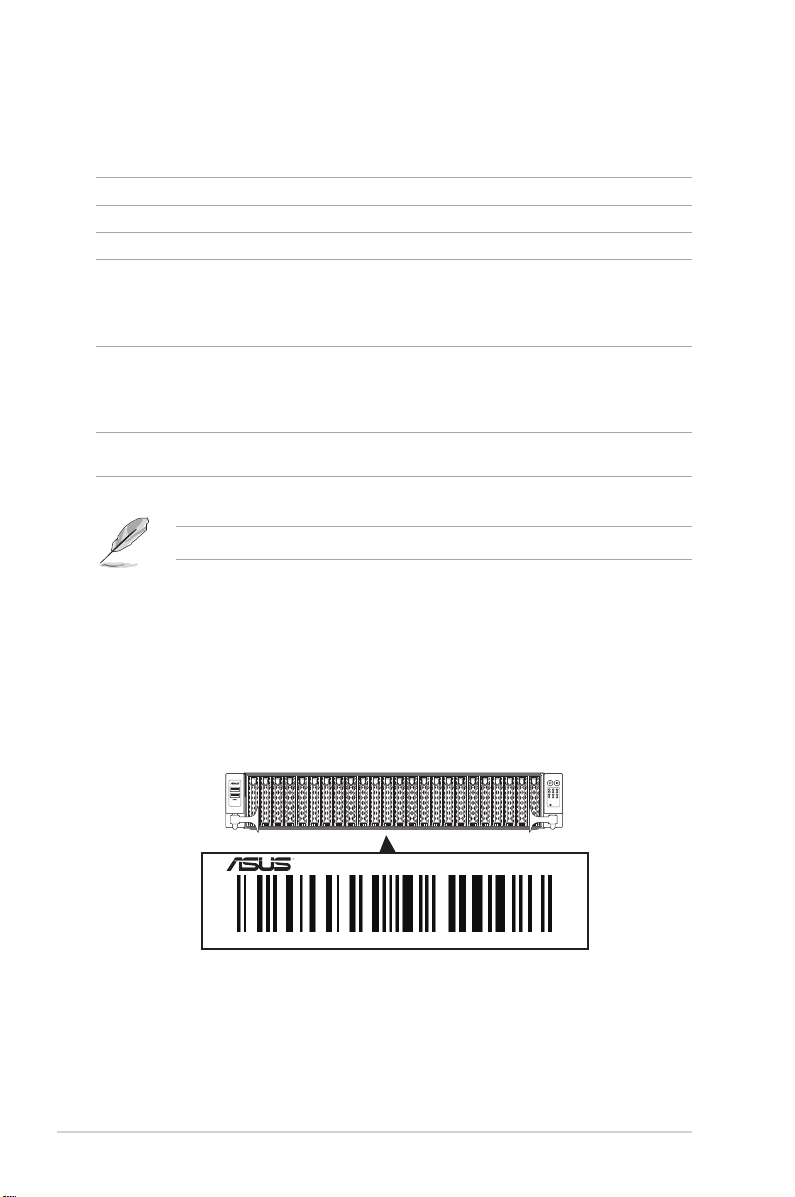
1.2 Serial number label
The product’s serial number contains 12 characters such as xxS0xxxxxxxx and printed on the
sticker at the server's front cover.
The correct serial number of the product is required if you need to request for support from
the ASUS Technical Support team.
1-2
RS720A-E11-RS24U
xxS0xxxxxxxx
Chapter 1: Product Introduction
Page 13
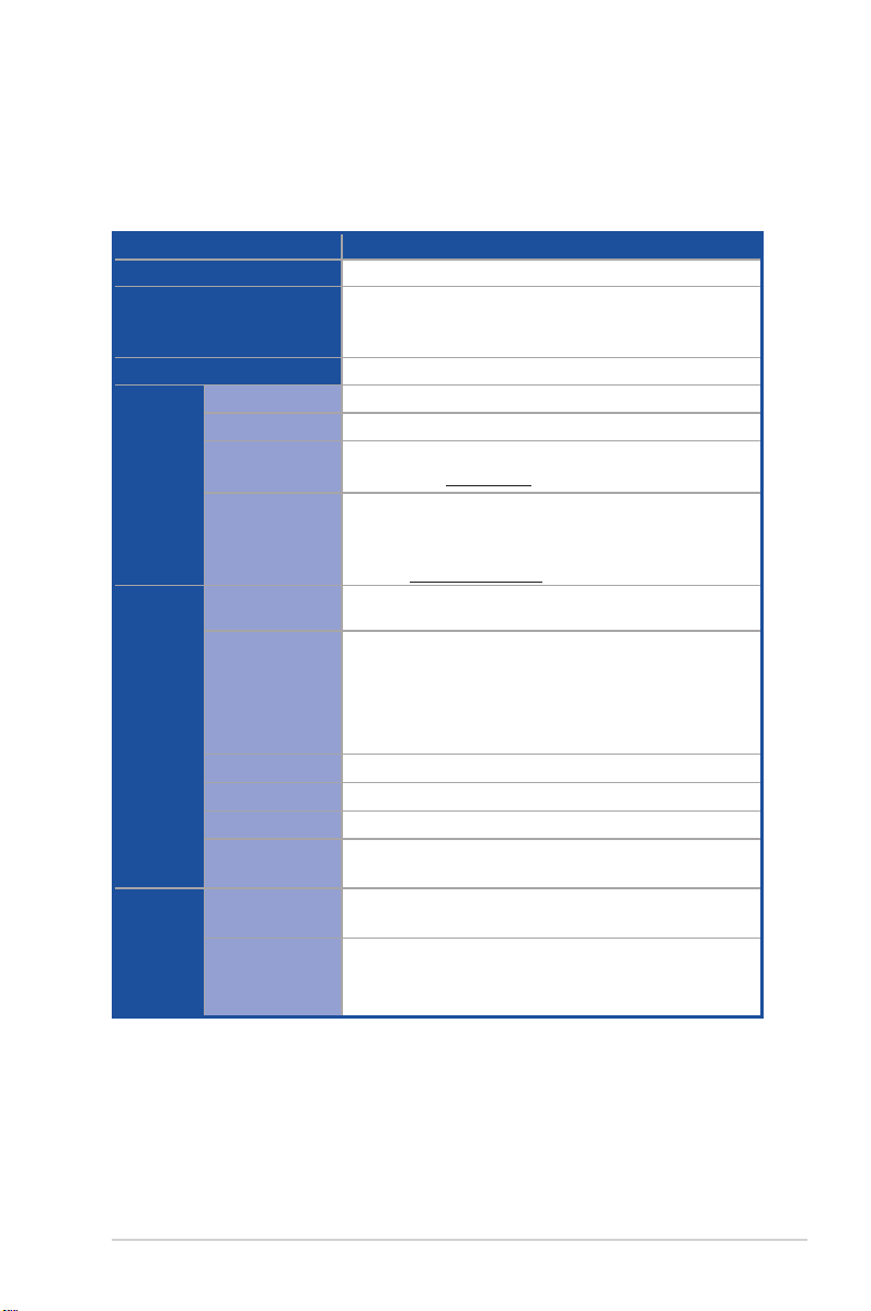
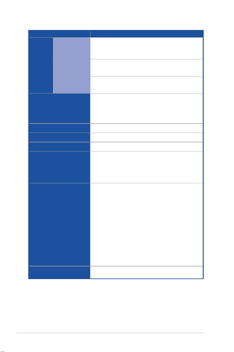
1.3 System specifications
The ASUS RS720A-E11-RS24U features the ASUS KMPP-D32 server board. The server
supports AMD EPYC™ 7002/7003 Series processors plus other latest technologies through
the chipsets onboard.
Model Name RS720A-E11-RS24U
Motherboard
Processor Support
Core Logic
Total Slots
Capacity
Memory
Expansion
Slots
Disk
Controller
Memory Type
Memory Size
Total PCI/PCI-E/
PIKE Slots
Slot Type
M.2
Micro SD Card Slot
Proprietary Slot 1
Proprietary Slot 2
SATA Controller
SAS Controller
KMPP-D32
2 x Socket SP3 (LGA 4094)
AMD EPYC™ 7002/7003 Series
xGMI (External Global Memory Interface Link)
System on Chip (SoC)
32 (8-channel per CPU, 16 DIMM per CPU)
Maximum up to 4096GB
DDR4 3200/2933 RDIMM / LRDIMM / 3DS LRDIMM
* Please refer to www.asus.com for latest memory AVL update
64GB, 32GB, 16GB (RDIMM)
64GB, 128GB (LRDIMM)
64GB, 128GB, 256GB (LRDIMM 3DS / 3DS RDIMM)
* Refer to www.asus.com/support for more information
9
6 x PCIe Gen4 x8 or 3 x PCIe Gen4 x16, FHFL
(CPU1 x1, CPU2 x2)
2 x PCIe Gen4 x8 or 1 x PCIe Gen4 x16, FHFL
or OCP3.0 (CPU1)
1 x PCIe Gen4 x8/x16, LPHL
(if PCIe M.2 is in use, it will operate at x8 link) (CPU2)
2 x M.2 (Up to 22110) (CPU2) (Support SATA/PCIe M.2)
1
1 x PCIe Gen4 x8 (for PIKE card only)
4 x 1Gb RJ45 Lan Module Card or
2 x 10Gb RJ45 Lan Module Card
8 x SATA 6Gb/s ports
2 x M.2 connectors (SATA 6Gb/s & PCIe Gen4 x4 link)
Optional:
ASUS PIKE II 3008 8-port SAS 12Gb/s HBA card
ASUS PIKE II 3108 8-port SAS HW 12Gb/s RAID card
ASUS RS720A-E11-RS24U
(continued on the next page)
1-3
Page 14
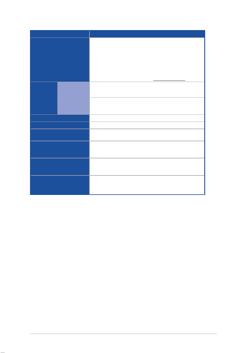
Model Name RS720A-E11-RS24U
24 x 2.5” Hot-Swap Drive Bays
(up to 8 x NVMe/SATA/SAS+16 x NVMe)
* SAS support only from optional SAS HBA/RAID card
* Support tri-mode card
2 x M.2 connectors
2 x miniSAS HD connector
Storage
Bays
Storage Bay
Motherboard onboard connectors
Default Cable
Networking
VGA
Graphic
Front I/O Ports
Rear I/O Ports
Switch/LED
Security Options
2 x MINI SAS HD to MINI SAS HD Cable
10 x SLIMELINE SAS HD Cable
1 x Quad port Intel® I350-AM4 1G LAN controller or
1 x Dual port Intel® X710-AT2 Gigabit 10G LAN controller
1 x Management Port
Optional OCP Adapter:
Up to 100Gb/s Ethernet / InfiniBand Adapter
Aspeed AST2600 64MB
4 double-wide GPUs or 8 double-wide GPUs
2 x USB 3.2 Gen 1 ports
2 x USB 3.2 Gen 1 ports
1 x VGA port
1 x RJ-45 Mgmt LAN port
4 x NIC ports
1 x OCP 3.0 port
Front Switch/LED:
1 x Power Switch (w/ LED)
1 x Reset Switch
1 x Location Switch (w/ LED)
1 x Storage Device Access LED
1 x Message LED
LAN 1-4 LED (on NIC module)
Rear Switch/LED:
1 x Q-Code/Port 80 LED
1 x Power Switch (w/ LED)
1 x Location Switch (w/ LED)
1 x Message LED
TPM-SPI
PFR
1-4
(continued on the next page)
Chapter 1: Product Introduction
Page 15
Model Name RS720A-E11-RS24U
Windows® Server 2019
RedHat® Enterprise Linux
SuSE® Linux Enterprise Server
OS Support
CentOS
Ubuntu
VMware
* Please find the latest OS support from http://www.asus.com
Software
ASUS Control Center
Management
Solution
Out of Band
Remote
On-Board ASMB10-iKVM for KVM-over-IP
Hardware
Regulatory Compliance
Dimension
Net Weight Kg (CPU, DRAM &
storage device not included)
BSMI, CE, C-Tick, FCC(Class A)
840 mm x 449 mm x 88.1 mm (2U)
39.3 Kg
Gross Weight Kg (CPU, DRAM
& storage device not included,
49.6 Kg
packing included)
Power Supply
(different configuration
by region)
1+1 Redundant 1600W/2400W 80 PLUS Platinum Power Supply
Rating: 100-127/200-240Vac, 9.4A/4.72A (x2), 50/60Hz Class I
(240Vdc, 4.6A Only for China)
Operating temperature: 10°C ~ 35°C
Environment
Non operating temperature: -40°C ~ 60°C
Non operating humidity: 20% ~ 90% (Non condensing)
* Specifications are subject to change without notice.
ASUS RS720A-E11-RS24U
1-5
Page 16
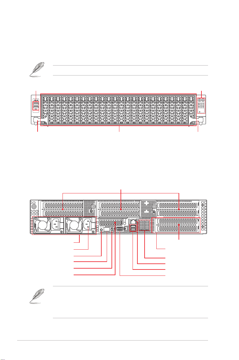
1.4 Front panel features
The barebone server displays a simple yet stylish front panel with easily accessible features.
The power and reset buttons, LED indicators, and two USB ports are located on the front
panel.
Refer to section 1.7 LED information for the LED descriptions.
USB 3.2 Gen 1 ports
handle
24 x 2.5” Storage Bays
Front panel LEDs & buttons
1 2
3 4
RESET
handle
1.5 Rear panel features
The rear panel includes the expansion slots, system power sockets, and rear fans. The
middle part includes the I/O shield with openings for the rear panel connectors on the
motherboard.
Expansion slot
Redundant power supply
Power connector
Power button
Q-Code LED
Location button
Expansion slot
Expansion slot
Optional External Fan location
(for GPU model)
Optional LAN port expansion slots
Mgmt LAN port*
USB 3.2 Gen 1 ports
VGA port
1-6
• * This port is for ASUS ASMB10-iKVM only.
• The Q-Code LED provides the most probable cause of an error code as a starting
point for troubleshooting. The actual cause may vary from case to case.
• Refer to the Q-Code table for details.
Chapter 1: Product Introduction
Page 17
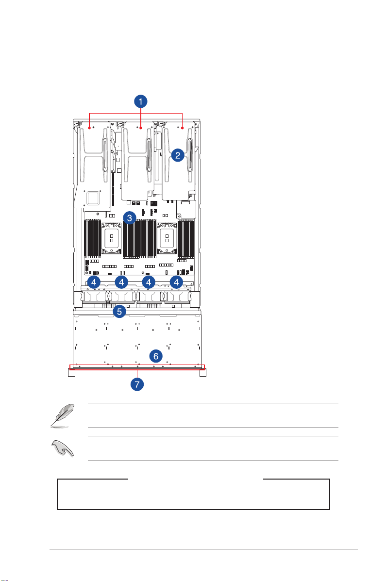
1.6 Internal features
The barebone server includes the basic components as shown.
Non-GPU model
1. Riser card bracket
2. Redundant Power supply
(hidden)
3. ASUS KMPP-D32 Server
Board
4. System fans
5. SATA/SAS back panel
6. Front panel (hidden)
7. 24 x 2.5” storage device trays
The barebone server does not include a floppy disk drive. Connect a USB floppy disk drive to
any of the USB ports on the front or rear panel if you need to use a floppy disk.
A protection film is pre-attached to the front cover before shipping. Please remove the
protection film before turning on the system for proper heat dissipation.
KEEP FINGERS AND OTHER BODY PARTS AWAY
ASUS RS720A-E11-RS24U
HAZARDOUS MOVING PARTS
WARNING
1-7
Page 18
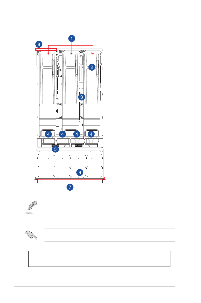
GPU model
1. Riser card bracket
2. Redundant Power supply
(hidden)
3. ASUS KMPP-D32 Server
Board
4. System fans
5. SATA/SAS back panel
6. Front panel (hidden)
7. 24 x 2.5” storage device trays
8. External Fan* (optional)
1-8
• * Ensure to install the external fan when GPU is installed on slot 3 & 4.
• The barebone server does not include a floppy disk drive. Connect a USB floppy disk
drive to any of the USB ports on the front or rear panel if you need to use a floppy
disk.
A protection film is pre-attached to the front cover before shipping. Please remove the
protection film before turning on the system for proper heat dissipation.
WARNING
HAZARDOUS MOVING PARTS
KEEP FINGERS AND OTHER BODY PARTS AWAY
Chapter 1: Product Introduction
Page 19
1.7 LED information
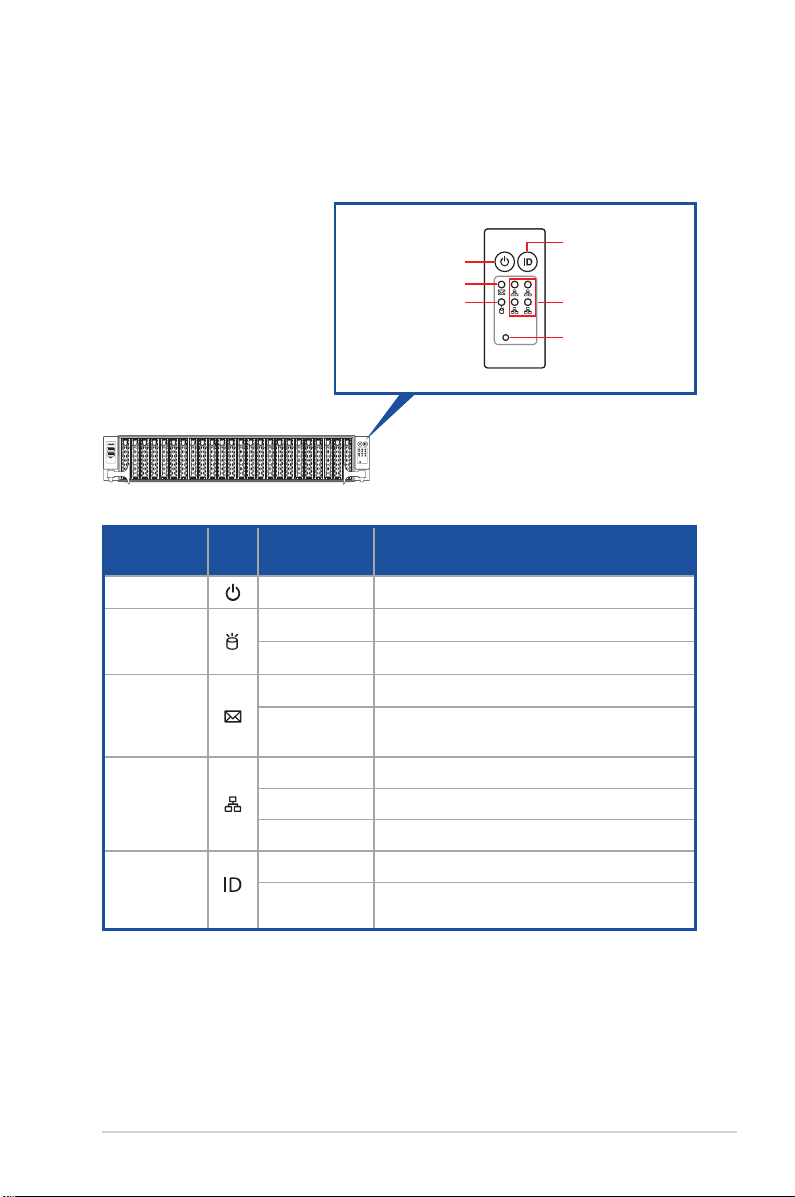
1.7.1 Front panel LEDs
Power button
Message LED
Storage device
access LED
1 2
3 4
RESET
LED Icon Display status Description
Power LED ON System power ON
Storage
device access
LED
Message LED
LAN LEDs
Location LED
OFF No activity
Blinking Read/write data into the storage device
OFF System is normal; no incoming event
ON
With the onboard ASMB10-iKVM: a hardware
monitor event is indicated
OFF No LAN connection
Blinking LAN is transmitting or receiving data
ON LAN connection is present
ON Location switch is pressed
OFF
Normal status (Press the location switch again
to turn off)
RESET
1 2
3 4
Location button
LAN LEDs
RESET button
ASUS RS720A-E11-RS24U
1-9
Page 20
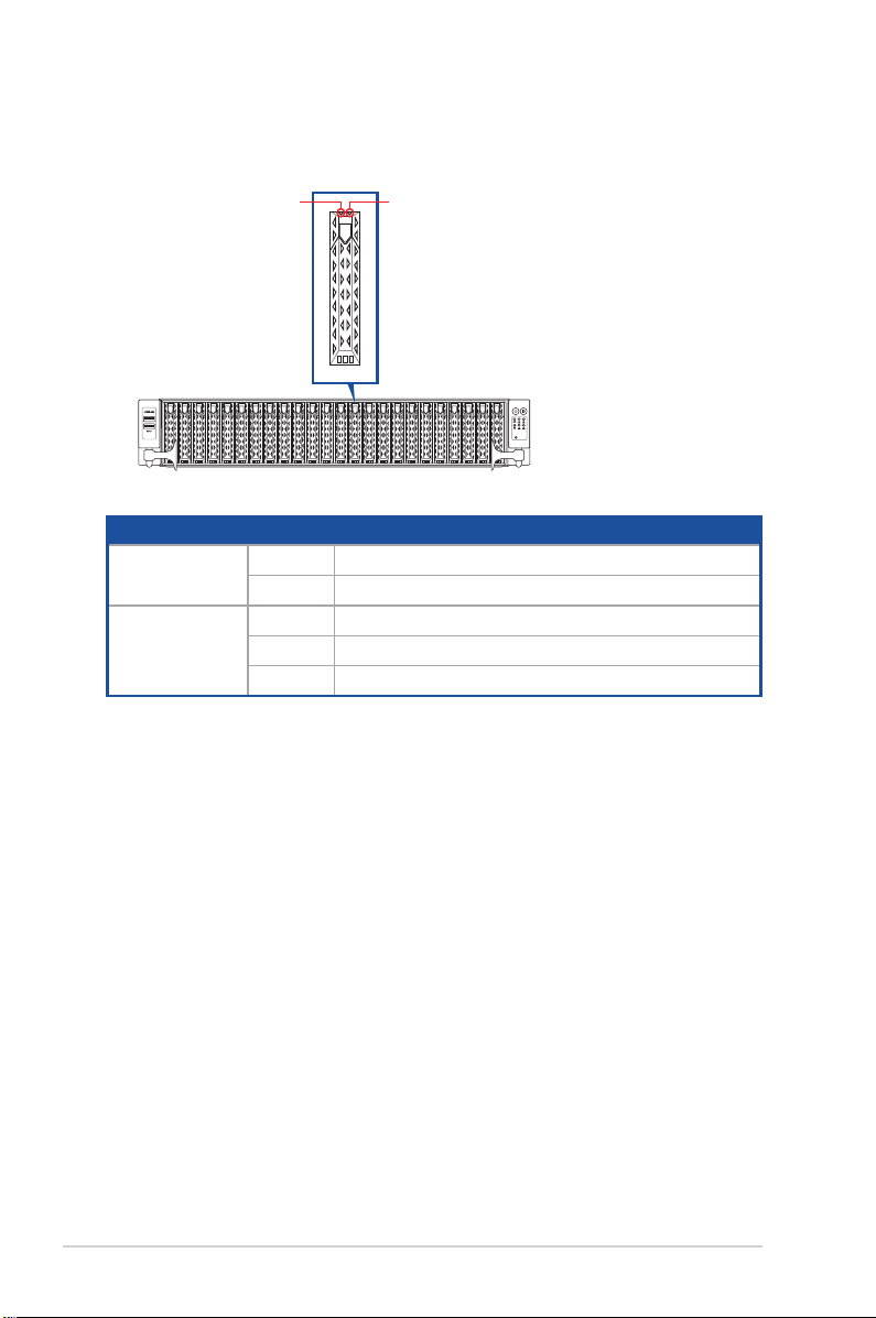
1.7.2 Storage device status LED
Red LEDGreen LED
Storage Device LED Description
Status (RED)
Activity (GREEN)
ON Storage device has failed
Blinking RAID rebuilding or locating
ON Storage device power ON
Blinking Read/write data from/into the SATA/SAS storage device
OFF Storage device not found
1 2
3 4
RESET
1-10
Chapter 1: Product Introduction
Page 21
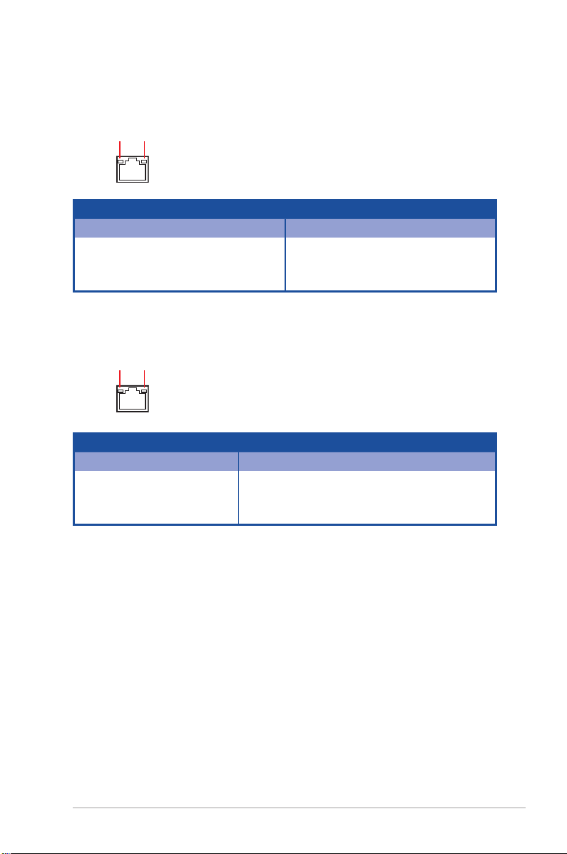
1.7.3 LAN (RJ-45) LEDs
Intel® I350-AM4 1G LAN port LEDs
ACT/LINK LED SPEED LED
ACT/LINK LED SPEED LED
Status Description Status Description
OFF No link OFF 10 Mbps connection
GREEN Linked ORANGE 100 Mbps connection
BLINKING Data activity GREEN 1 Gbps connection
Intel® X710-AT2 Gigabit 10G LAN port LEDs
ACT/LINK LED SPEED LED
ACT/LINK LED SPEED LED
Status Description Status Description
OFF No link OFF 10 Mbps / 100 Mbps connection
GREEN Linked ORANGE 1 Gbps connection
BLINKING Data activity GREEN 10 Gbps connection
ASUS RS720A-E11-RS24U
1-11
Page 22
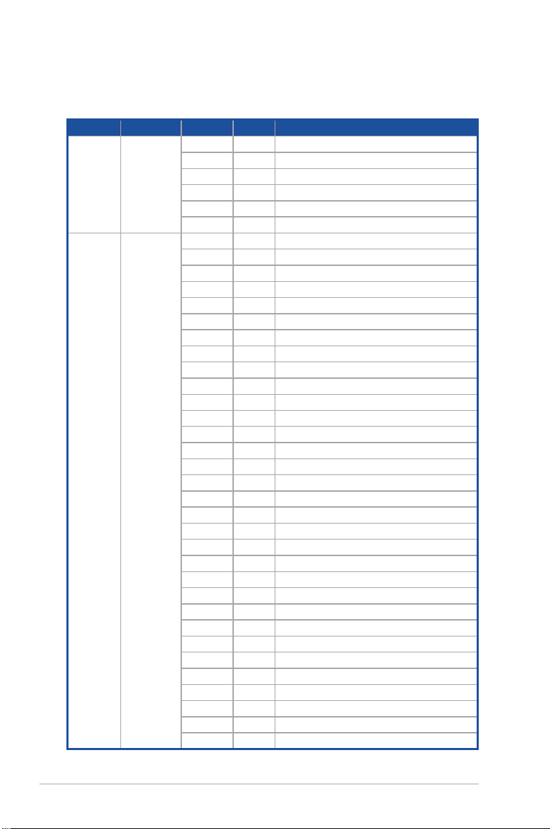
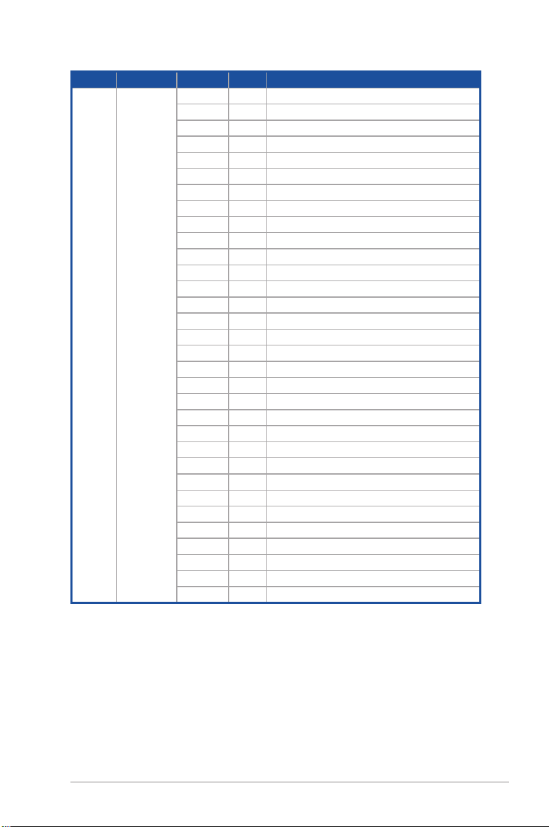
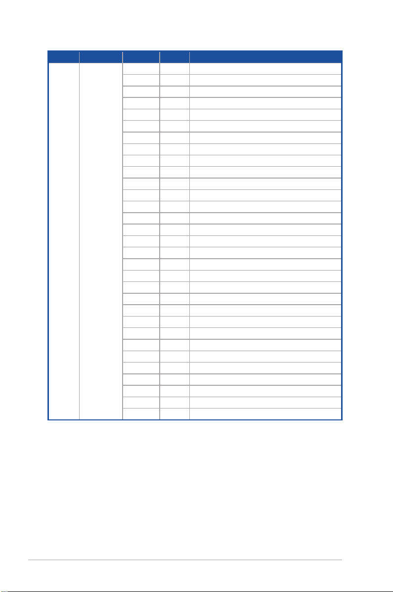
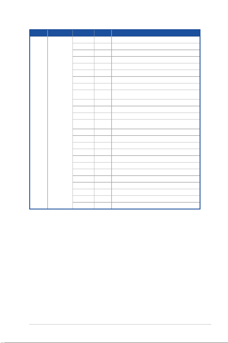
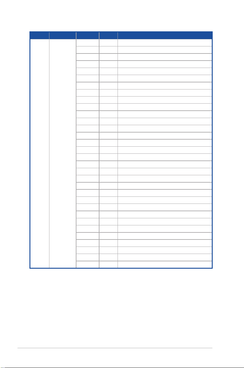
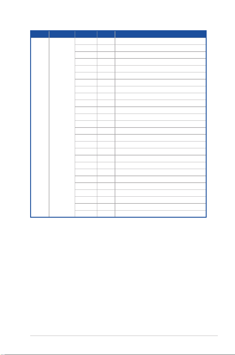
1.7.4 Q-Code table
AMD EPYC™ 7002 Series processors
Action PHASE POST CODE TYPE DESCRIPTION
0x01 Progress First post code
0x02 Progress Load BSP microcode
SEC Start up Security Phase
PSP Boot
PSP Boot Loader
phase (Error Post
Codes)
0x03 Progress Perform early platform Initialization
0x04 Progress Set cache as ram for PEI phase
0x05 Progress Establish Stack
0x06 Progress CPU Early Initialization
0x00 Error General - Success
0x01 Error Generic Error Code
0x02 Error Generic Memory Error
0x03 Error Buffer Overflow
0x04 Error Invalid Parameter(s)
0x05 Error Invalid Data Length
0x06 Error Data Alignment Error
0x07 Error Null Pointer Error
0x08 Error Unsupported Function
0x09 Error Invalid Service ID
0x0A Error Invalid Address
0x0B Error Out of Resource Error
0x0C Error Timeout
0x0D Error data abort exception
0x0E Error prefetch abort exception
0x0F Error Out of Boundary Condition Reached
0x10 Error Data corruption
0x11 Error Invalid command
0x12 Error The package type provided by BR is incorrect
0x13 Error Failed to retrieve FW header during FW validation
0x14 Error Key size not supported
0x15 Error Agesa0 verification error
0x16 Error SMU FW verification error
0x17 Error OEM SINGING KEY verification error
0x18 Error Generic FW Validation error
0x19 Error RSA operation fail - bootloader
0x1A Error CCP Passthrough operation failed - internal status
0x1B Error AES operation fail
0x1C Error CCP state save failed
0x1D Error CCP state restore failed
0x1E Error SHA256 operation fail - internal status
0x1F Error ZLib Decompression operation fail
(continued on the next page)
1-12
Chapter 1: Product Introduction
Page 23
Action PHASE POST CODE TYPE DESCRIPTION
0x20 Error HMAC-SHA256 operation fail - internal status
0x21 Error Booted from boot source not recognized by PSP
0x22 Error PSP directory entry not found
0x23 Error PSP failed to set the write enable latch
0x24 Error PSP timed out because spirom took too long
0x25 Error Cannot find BIOS directory
0x26 Error SpiRom is not valid
0x27 Error slave die has different security state from master
0x28 Error SMI interface init failure
0x29 Error SMI interface generic error
0x2A Error invalid die ID executes MCM related function
0x2B Error invalid MCM configuration table read from bootrom
0x2C Error Valid boot mode wasn't detected
0x2D Error NVStorage init failure
0x2E Error NVStorage generic error
PSP Boot
PSP Boot Loader
phase (Error Post
Codes)
0x2F Error MCM 'error' to indicate slave has more data to send
0x30 Error MCM error if data size exceeds 32B
0x31 Error Invalid client id for SVC MCM call
0x32 Error MCM slave status register contains bad bits
0x33 Error MCM call was made in a single die environment
0x34 Error PSP secure mapped to invalid segment (should be 0x400_0000)
0x35 Error No physical x86 cores were found on die
0x36 Error Insufficient space for secure OS (range of free SRAM to SVC stack base)
0x37 Error SYSHUB mapping memory target type is not supported
0x38 Error Attempt to unmap permanently mapped TLB to PSP secure region
0x39 Error Unable to map an SMN address to AXI space
0x3A Error Unable to map a SYSHUB address to AXI space
0x3B Error The count of CCXs or cores provided by bootrom is not consistent
0x3C Error Uncompressed image size doesn’t match value in compressed header
0x3D Error Compressed option used in case where not supported
0x3E Error Fuse info on all dies don’t match
0x3F Error PSP sent message to SMU; SMU reported an error
ASUS RS720A-E11-RS24U
(continued on the next page)
1-13
Page 24
Action PHASE POST CODE TYPE DESCRIPTION
0x40 Error Function RunPostX86ReleaseUnitTests failed in memcmp()
0x41 Error Interface between PSP to SMU not available.
0x42 Error Timer wait parameter too large
0x43 Error Test harness module reported an error
0x44 Error x86 wrote C2PMSG_0 interrupting PSP
0x45 Error A write to an L3 register failed
0x46 Error Mini-BL
0x47 Error Mini-BL CCP HMAC Unit-test failed
0x48 Error Potential stack corruption in jump to Mini BL
0x49 Error Error in Validate and Loading AGESA APOB SVC call
0x4A Error Correct fuse bits for DIAG_BL loading not set
0x4B Error The UmcProgramKeys() function was not called by AGESA
0x4C Error Secure unlock error
0x4D Error Syshub register programming mismatch during readback
0x4E Error Family ID in MP0_SFUSE_SEC[7:3] not correct
0x4F Error An operation was invoked that can only be performed by the GM
0x50 Error Failed to acquire host controller semaphore to claim ownership of SMB
0x51 Error Timed out waiting for host to complete pending transactions
0x52 Error Timed out waiting for slave to complete pending transactions
0x53 Error Unable to kill current transaction on host
0x54 Error One of: Illegal command
0x55 Error An SMBus transaction collision detected
0x56 Error Transaction failed to be started or processed by host
0x57 Error An unsolicited SMBus interrupt was received
0x58 Error An attempt to send an unsupported PSP-SMU message was made
0x59 Error An error/data corruption detected on response from SMU for sent msg
0x5A Error MCM Steady-state unit test failed
0x5B Error S3 Enter failed
0x5C Error AGESA BL did not set PSP SMU reserved addresses via SVC call
0x5E Error CcxSecBisiEn not set in fuse RAM
0x5F Error Received an unexpected result
PSP Boot
PSP Boot Loader
phase (Error Post
Codes)
1-14
(continued on the next page)
Chapter 1: Product Introduction
Page 25
Action PHASE POST CODE TYPE DESCRIPTION
0x60 Error VMG Storage Init failed
0x61 Error Failure in mbedTLS user app
0x62 Error An error occured whilst attempting to SMN map a fuse register
0x63 Error Fuse burn sequence/operation failed due to internal SOC error
0x64 Error Fuse sense operation timed out
0x65 Error Fuse burn sequence/operation timed out waiting for burn done
0x66 Error Failure status indicating that the given SecureOS has been
0x67 Error This PSP FW was revoked
The platform model/vendor id fuse is not matching the BIOS public
key token
HVB validation failure for BIOS RTM volume (OEM public/signature
failed to validate).
PSP Boot
PSP Boot Loader
phase (Error Post
Codes)
0x68 Error
0x69 Error The BIOS OEM public key of the BIOS was revoked for this platform
0x6A Error PSP level 2 directory not match expected value.
0x6B Error BIOS level 2 directory not match expected value.
0x6C Error
0x6D Error Generic error indicating the CCP HAL initialization failed
0x94 Error Knoll failed to idle correctly after being reset
0x95 Error Bad status returned by I2CKnollCheck
0x96 Error NACK to general call (no device on Knoll I2C bus)
0x97 Error Null pointer passed to I2CKnollCheck
0x98 Error Invalid device-ID found during Knoll authentication
0x99 Error Error during Knoll/Prom key derivation
0x9A Error Null pointer passed to Crypto function
0x9B Error Error in checksum from wrapped Knoll/Prom keys
0x9C Error Knoll returned an invalid response to a command
0x9D Error Bootloader failed in Knoll Send Command function
0x9E Error No Knoll device found by verifying MAC
ASUS RS720A-E11-RS24U
(continued on the next page)
1-15
Page 26
Action PHASE POST CODE TYPE DESCRIPTION
0xA0 Progress Bootloader successfully entered C Main
0xA1 Progress Master initialized C2P / slave waited for master to init C2P
0xA2 Progress HMAC key successfully derived
0xA3 Progress Master got Boot Mode and sent boot mode to all slaves
0xA4 Progress SpiRom successfully initialized
0xA5 Progress BIOS Directory successfully read from SPI to SRAM
0xA6 Progress Early unlock check
0xA7 Progress Inline Aes key successfully derived
0xA8 Progress Inline-AES key programming is done
0xA9 Progress Inline-AES key wrapper derivation is done
0xAA Progress Bootloader successfully loaded HW IP configuration values
0xAB Progress Bootloader successfully programmed MBAT table
0xAC Progress Bootloader successfully loaded SMU FW
0xAD Progress PSP and SMU configured WAFL
0xAE Progress User mode test harness completed successfully
PSP Boot
PSP Boot Loader
phase (Status
Post Codes)
0xAF Progress Bootloader loaded Agesa0 from SpiRom
0xB0 Progress AGESA phase has completed
0xB1 Progress RunPostDramTrainingTests() completed successfully
0xB2 Progress SMU FW Successfully loaded to SMU Secure DRAM
0xB3 Progress Sent all required boot time messages to SMU
0xB4 Progress Validated and ran Security Gasket binary
0xB5 Progress UMC Keys generated and programmed
0xB6 Progress Inline AES key wrapper stored in DRAM
0xB7 Progress Completed FW Validation step
0xB8 Progress Completed FW Validation step
0xB9 Progress BIOS copy from SPI to DRAM complete
0xBA Progress Completed FW Validation step
0xBB Progress BIOS load process fully complete
0xBC Progress Bootloader successfully release x86
0xBD Progress Early Secure Debug completed
0xBE Progress GetFWVersion command received from BIOS is completed
0xBF Progress SMIInfo command received from BIOS is completed
(continued on the next page)
1-16
Chapter 1: Product Introduction
Page 27
Action PHASE POST CODE TYPE DESCRIPTION
0xC0 Progress Successfully entered WarmBootResume()
0xC1 Progress Successfully copied SecureOS image to SRAM
0xC2 Progress Successfully copied trustlets to PSP Secure Memory
0xC3 Progress About to jump to Secure OS (SBL about to copy and jump)
0xC4 Progress Successfully restored CCP and UMC state on S3 resume
0xC5 Progress PSP SRAM HMAC validated by Mini BL
0xC6 Progress About to jump to <t-base in Mini BL
0xC7 Progress VMG ECDH unit test started
0xC8 Progress VMG ECDH unit test passed
0xC9 Progress VMG ECC CDH primitive unit test started
0xCA Progress VMG ECC CDH primitive unit test passed
0xCB Progress VMG SP800-108 KDF-CTR HMAC unit test started
PSP Boot
PSP Boot Loader
phase (Status
Post Codes)
0xCC Progress VMG SP800-108 KDF-CTR HMAC unit test passed
0xCD Progress VMG LAUNCH_* test started
0xCE Progress VMG LAUNCH_* test passed
0xCF Progress MP1 has been taken out of reset
0xD0 Progress PSP and SMU Reserved Addresses correct
0xD1 Progress Reached Naples steady-state WFI loop
0xD2 Progress Knoll device successfully initialized
0xD3 Progress 32-byte RandOut successfully returned from Knoll
0xD4 Progress 32-byte MAC successfully received from Knoll.
0xD5 Progress Knoll device verified successfully
0xD6 Progress Done enabling power for Knoll
0xD7 Progress Enter recovery mode due to trustlet validation fail.
0xD8 Progress Enter recovery mode due to OS validation fail.
0xD9 Progress Enter recovery mode due to OEM public key not found.
(continued on the next page)
ASUS RS720A-E11-RS24U
1-17
Page 28
Action PHASE POST CODE TYPE DESCRIPTION
0x10 Progress PEI Core Entry
0x11 Progress PEI cache as ram CPU initial
0x15 Progress NB Initialization before installed memory
0x19 Progress SB Initialization before installed memory
0x32 Progress CPU POST-Memory Initialization
0x33 Progress CPU Cache Initialization
0x34 Progress Application Processor(s) (AP) Initialization
0x35 Progress BSP Selection
0x36 Progress CPU Initialization
0x37 Progress Pre-memory NB Initialization
0x3B Progress Pre-memory SB Initialization
0x4F Progress DXE Initial Program Load(IPL)
0x60 Progress DXE Core Started
0x61 Progress DXE NVRAM Initialization
0x62 Progress SB run-time Initialization
0x63 Progress CPU DXE Initialization
0x68 Progress PCI HB Initialization
0x69 Progress NB DXE Initialization
0x6A Progress NB DXE SMM Initialization
0x70 Progress SB DXE Initialization
0x71 Progress SB DXE SMM Initialization
0x72 Progress SB DEVICES Initialization
0x78 Progress ACPI Module Initialization
0x79 Progress CSM Initialization
0xD0 Progress CPU PM Structure Initialization
0x90 Progress BDS started
0x91 Progress Connect device event
0x92 Progress PCI Bus Enumeration
0x93 Progress PCI Bus Enumeration
0x94 Progress PCI Bus Enumeration
0x95 Progress PCI Bus Enumeration
0x96 Progress PCI Bus Enumeration
0x97 Progress Console outout connect event
0x98 Progress Console input connect event
0x99 Progress AMI Super IO start
0x9A Progress AMI USB Driver Initialization
0x9B Progress AMI USB Driver Initialization
0x9C Progress AMI USB Driver Initialization
0x9D Progress AMI USB Driver Initialization
Quick VGA
Normal
boot
PEI(Pre-EFI
Initialization)
phase
DXE(Driver
Execution
Environment)
phase
BDS(Boot Device
Selection) phase
(continued on the next page)
1-18
Chapter 1: Product Introduction
Page 29
Action PHASE POST CODE TYPE DESCRIPTION
0xb2 Progress Legacy Option ROM Initialization
0xb3 Progress Reset system
0xb4 Progress USB hotplug
0xb6 Progress NVRAM clean up
0xb7 Progress NVRAM configuration reset
0xA0 Progress IDE, AHCI Initialization
0xA1 Progress IDE, AHCI Initialization
0xA2 Progress IDE, AHCI Initialization
0xA3 Progress IDE, AHCI Initialization
0x00~0xFF Progress Wait BMC ready
0xA8 Progress BIOS Setup Utility password verify
0xA9 Progress BIOS Setup Utility start
0xAB Progress BIOS Setup Utility input wait
0xAD Progress Ready to boot event
0xAE Progress Legacy boot event
0xAA Progress APIC mode
0xAC Progress PIC mode
Normal
boot
BDS(Boot Device
Selection) phase
Operating system
phase
(continued on the next page)
ASUS RS720A-E11-RS24U
1-19
Page 30
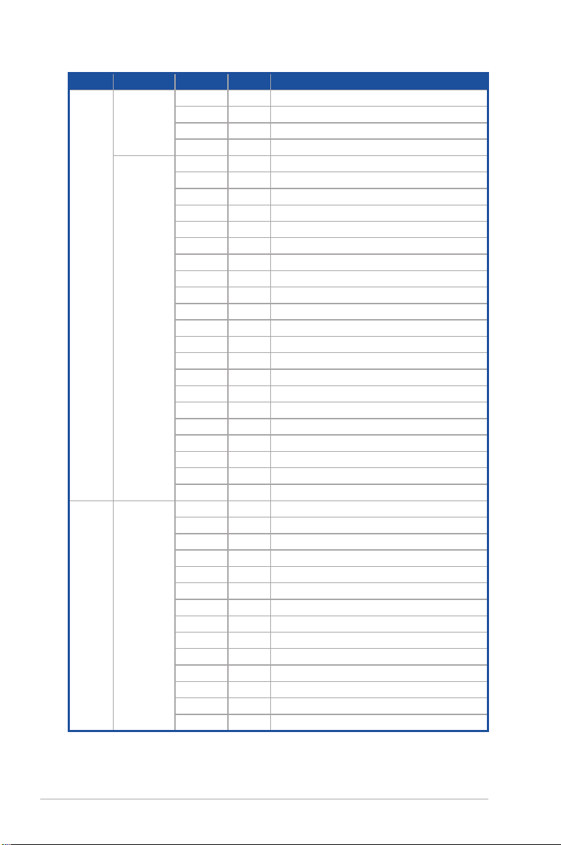
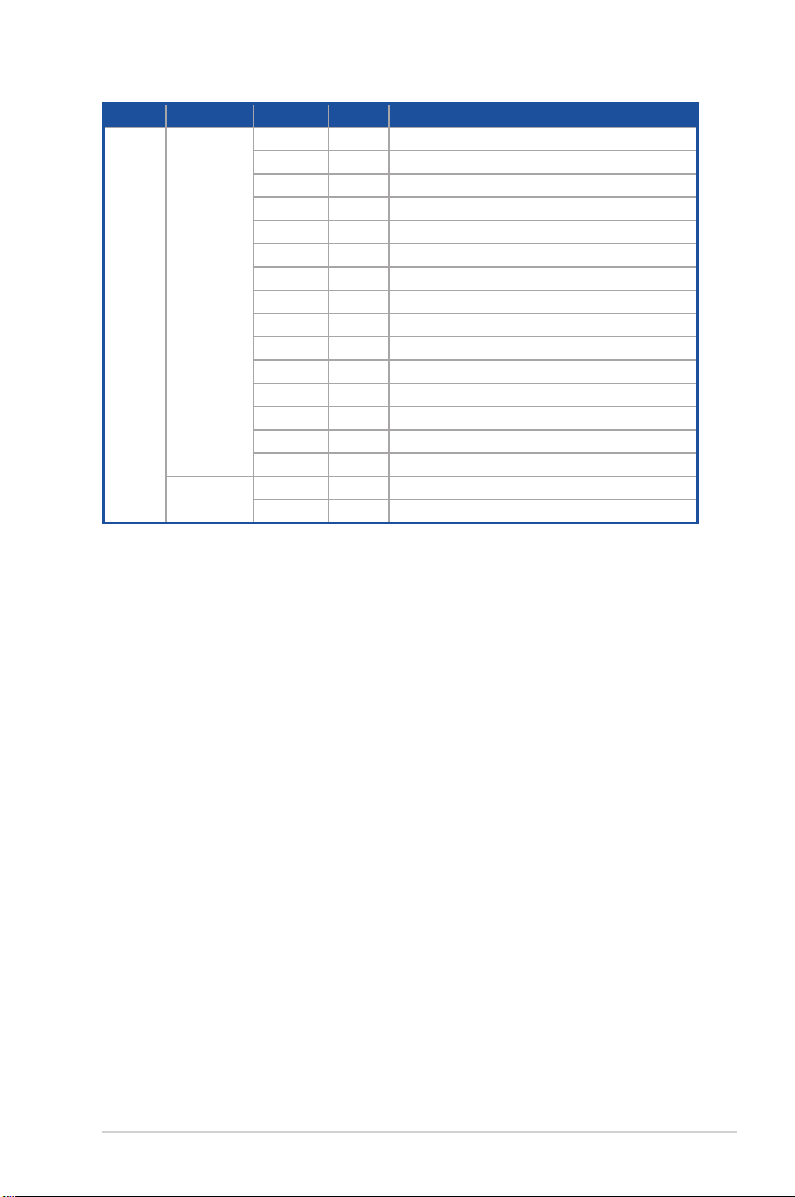
AMD EPYC™ 7003 Series processors
Action PHASE POST CODE TYPE DESCRIPTION
0x01 Progress First post code
0x02 Progress Load BSP microcode
SEC Start
up
PSP Boot
Security Phase
PSP Boot Loader
phase (Error Post
Codes)
0x03 Progress Perform early platform Initialization
0x04 Progress Set cache as ram for PEI phase
0x05 Progress Establish Stack
0x06 Progress CPU Early Initialization
0x00 error General - Success
0x01 error Generic Error Code
0x02 error Generic Memory Error
0x03 error Buffer Overflow
0x04 error Invalid Parameter(s)
0x05 error Invalid Data Length
0x06 error Data Alignment Error
0x07 error Null Pointer Error
0x08 error Unsupported Function
0x09 error Invalid Service ID
0x0A error Invalid Address
0x0B error Out of Resource Error
0x0C error Timeout
0x0D error data abort exception
0x0E error prefetch abort exception
0x0F error Out of Boundary Condition Reached
0x10 error Data corruption
0x11 error Invalid command
0x12 error The package type provided by BR is incorrect
0x13 error Failed to retrieve FW header during FW validation
0x14 error Key size not supported
0x15 error Agesa0 verification error
0x16 error SMU FW verification error
0x17 error OEM SINGING KEY verification error
0x18 error Generic FW Validation error
0x19 error RSA operation fail - bootloader
0x1A error CCP Passthrough operation failed - internal status
0x1B error AES operation fail
0x1C error CCP state save failed
0x1D error CCP state restore failed
0x1E error SHA256/384 operation fail - internal status
0x1F error ZLib Decompression operation fail
(continued on the next page)
1-20
Chapter 1: Product Introduction
Page 31

Action PHASE POST CODE TYPE DESCRIPTION
0x20 error HMAC-SHA256/384 operation fail - internal status
0x21 error Booted from boot source not recognized by PSP
0x22 error PSP directory entry not found
0x23 error PSP failed to set the write enable latch
0x24 error PSP timed out because spirom took too long
0x25 error Cannot find BIOS directory
0x26 error SpiRom is not valid
0x27 error slave die has different security state from master
0x28 error SMI interface init failure
0x29 error SMI interface generic error
0x2A error invalid die ID executes MCM related function
0x2B error invalid MCM configuration table read from bootrom
PSP Boot
PSP Boot Loader
phase (Error Post
Codes)
0x2C error Valid boot mode wasn't detected
0x2D error NVStorage init failure
0x2E error NVStorage generic error
0x2F error MCM 'error' to indicate slave has more data to send
0x30 error MCM error if data size exceeds 32B
0x31 error Invalid client id for SVC MCM call
0x32 error MCM slave status register contains bad bits
0x33 error MCM call was made in a single die environment
0x34 error PSP secure mapped to invalid segment (should be 0x400_0000)
0x35 error No physical x86 cores were found on die
0x36 error Insufficient space for secure OS (range of free SRAM to SVC stack base)
0x37 error SYSHUB mapping memory target type is not supported
0x38 error Attempt to unmap permanently mapped TLB to PSP secure region
0x39 error Unable to map an SMN address to AXI space
ASUS RS720A-E11-RS24U
(continued on the next page)
1-21
Page 32

Action PHASE POST CODE TYPE DESCRIPTION
0x3A error Unable to map a SYSHUB address to AXI space
0x3B error The count of CCXs or cores provided by bootrom is not consistent
0x3C error Uncompressed image size doesn't match value in compressed header
0x3D error Compressed option used in case where not supported
0x3E error Fuse info on all dies don't match
0x3F error PSP sent message to SMU; SMU reported an error
0x40 error Function RunPostX86ReleaseUnitTests failed in memcmp()
0x41 error Interface between PSP to SMU not available.
0x42 error Timer wait parameter too large
0x43 error Test harness module reported an error
x86 wrote C2PMSG_0 interrupting PSP, but the command has an
invalid format
PSP Boot
PSP Boot Loader
phase (Error Post
Codes)
0x44 error
0x45 error Failed to read from SPI the Bios Directory or Bios Combo Directory
0x46 error Mini-BL, validation of the PSP SRAM image failed on HMAC compare
0x47 error Failed to read the combo bios header
0x48 error Potential stack corruption in jump to Mini BL
0x49 error Error in Validate and Loading AGESA APOB SVC call
0x4A error Correct fuse bits for DIAG_BL loading not set
0x4B error The UmcProgramKeys() function was not called by AGESA
0x4C error Unconditional Unlock based on serial numbers failure
0x4D error Syshub register programming mismatch during readback
0x4E error Family ID in MP0_SFUSE_SEC[7:3] not correct
0x4F error An operation was invoked that can only be performed by the GM
0x50 error Failed to acquire host controller semaphore to claim ownership of SMB
0x51 error Timed out waiting for host to complete pending transactions
0x52 error Timed out waiting for slave to complete pending transactions
0x53 error Unable to kill current transaction on host, to force idle
0x54 error One of: Illegal command, Unclaimed cycle, or Host time out
0x55 error An smbus transaction collision detected, operation restarted
0x56 error Transaction failed to be started or processed by host, or not completed
0x57 error An unsolicited smbus interrupt was received
0x58 error An attempt to send an unsupported PSP-SMU message was made
0x59 error An error/data corruption detected on response from SMU for sent msg
0x5A error MCM Steady-state unit test failed
0x5B error S3 Enter failed
0x5C error AGESA BL did not set PSP SMU reserved addresses via SVC call
0x5E error CcxSecBisiEn not set in fuse RAM
0x5F error Received an unexpected result
(continued on the next page)
1-22
Chapter 1: Product Introduction
Page 33

Action PHASE POST CODE TYPE DESCRIPTION
0x60 error VMG Storage Init failed
0x61 error failure in mbedTLS user app
0x62 error An error occured whilst attempting to SMN map a fuse register
0x63 error Fuse burn sequence/operation failed due to internal SOC error
0x64 error Fuse sense operation timed out
0x65 error Fuse burn sequence/operation timed out waiting for burn done
0x66 error The PMU FW Public key certificate loading or authentication fails
0x67 error This PSP FW was revoked
The platform model/vendor id fuse is not matching the BIOS public
key token
PSP Boot
PSP Boot Loader
phase (Error Post
Codes)
0x68 error
0x69 error The BIOS OEM public key of the BIOS was revoked for this platform
0x6A error PSP level 2 directory not match expected value.
0x6B error BIOS level 2 directory not match expected value.
0x6C error Reset image not found
0x6D error Generic error indicating the CCP HAL initialization failed
0x6E error failure to copy NVRAM to DRAM.
0x6F error Invalid key usage flag
0x71 error RSMU signaled a security violation
0x72 error Error programming the WAFL PCS registers
0x73 error Error setting wafl PCS threshold value
0x74 error Error loading OEM trustlets
0x75 error Recovery mode accross all dies is not sync'd
0x76 error Uncorrectable WAFL error detected
0x77 error Fatal MP1 error detected
0x78 error Bootloader failed to find OEM signature
0x79 error Error copying BIOS to DRAM
0x7A error Error validating BIOS image signature
(continued on the next page)
ASUS RS720A-E11-RS24U
1-23
Page 34

Action PHASE POST CODE TYPE DESCRIPTION
0x7B error
0x7C error Platform Vendor ID and/or Model ID binding violation
Bootloader detects BIOS request boot from SPI-ROM, which is
unsupported for PSB.
(Local Master PSP on P1 socket) Platform Vendor ID and/or Model ID
binding violation
(Local Master PSP on P1 socket) Requested fuse is already blown,
reblow will cause ASIC malfunction
/ SEV download FW command fail to broadcase and clear the IsInSRAM
field on slave dies
The DXIO PHY SRAM Public key certificate loading or authentication
fails
fTPM binary size exceeds limit allocated in Private DRAM, need to
increase the limit
FW type mismatch between the requested FW type and the FW type
embedded in the FW binary header
PSP Boot
PSP Boot Loader
phase (Status
Post Codes)
0x7D error
0x7E error Requested fuse is already blown, reblow will cause ASIC malfunction
0x7F error Error with actual fusing operation
0x80 error (Local Master PSP on P1 socket) Error reading fuse info
0x81 error
0x82 error
0x83 error (Local Master PSP on P1 socket) Error with actual fusing operation
0x84 error SEV FW Rollback attempt is detected
0x85 error
0x86 error Agesa error injection failure
0x87 error Uncorrectable TWIX error detected
0x88 error Error programming the TWIX PCS registers
0x89 error Error setting TWIX PCS threshold value
0x8A error SW CCP queue is full, cannot add more entries
0x8B error CCP command description syntax error detected from input
0x8C error Return value stating that the command has not yet be scheduled
0x8D error The command is scheduled and being worked on
0x8E error
0x8F error
0x90 error The TWIX link for a particular CCD is not trained Fatal error
0x91 error Security check failed (not all dies are in same security state)
0x92 error
0x93 error SVC call input parameter address violation
0x94 error Knoll failed to idle correctly after being reset
0x95 error Bad status returned by I2CKnollCheck
0x96 error NACK to general call (no device on Knoll I2C bus)
0x97 error Null pointer passed to I2CKnollCheck
0x98 error Invalid device-ID found during Knoll authentication
0x99 error Error during Knoll/Prom key derivation
0x9A error Null pointer passed to Crypto function
0x9B error Error in checksum from wrapped Knoll/Prom keys
0x9C error Knoll returned an invalid response to a command
0x9D error Bootloader failed in Knoll Send Command function
0x9E error No Knoll device found by verifying MAC
0x9F error The maximum allowable error post code
(continued on the next page)
1-24
Chapter 1: Product Introduction
Page 35

Action PHASE POST CODE TYPE DESCRIPTION
0x10 Progress PEI Core Entry
0x11 Progress PEI cache as ram CPU initial
0x15 Progress NB Initialization before installed memory
0x19 Progress SB Initialization before installed memory
0x32 Progress CPU POST-Memory Initialization
0x33 Progress CPU Cache Initialization
0x34 Progress Application Processor(s) (AP) Initialization
0x35 Progress BSP Selection
0x36 Progress CPU Initialization
0x37 Progress Pre-memory NB Initialization
0x3B Progress Pre-memory SB Initialization
0x4F Progress DXE Initial Program Load(IPL)
0x60 Progress DXE Core Started
0x61 Progress DXE NVRAM Initialization
0x62 Progress SB run-time Initialization
0x63 Progress CPU DXE Initialization
0x68 Progress PCI HB Initialization
0x69 Progress NB DXE Initialization
0x6A Progress NB DXE SMM Initialization
0x70 Progress SB DXE Initialization
0x71 Progress SB DXE SMM Initialization
0x72 Progress SB DEVICES Initialization
0x78 Progress ACPI Module Initialization
0x79 Progress CSM Initialization
0xD0 Progress CPU PM Structure Initialization
Quick VGA
PEI(Pre-EFI
Initialization)
phase
DXE(Driver
Execution
Environment)
phase
ASUS RS720A-E11-RS24U
(continued on the next page)
1-25
Page 36

Action PHASE POST CODE TYPE DESCRIPTION
0x90 Progress BDS started
0x91 Progress Connect device event
0x92 Progress PCI Bus Enumeration
0x93 Progress PCI Bus Enumeration
0x94 Progress PCI Bus Enumeration
0x95 Progress PCI Bus Enumeration
0x96 Progress PCI Bus Enumeration
0x97 Progress Console outout connect event
0x98 Progress Console input connect event
0x99 Progress AMI Super IO start
0x9A Progress AMI USB Driver Initialization
0x9B Progress AMI USB Driver Initialization
0x9C Progress AMI USB Driver Initialization
0x9D Progress AMI USB Driver Initialization
0xb2 Progress Legacy Option ROM Initialization
0xb3 Progress Reset system
0xb4 Progress USB hotplug
0xb6 Progress NVRAM clean up
0xb7 Progress NVRAM configuration reset
0xA0 Progress IDE, AHCI Initialization
0xA1 Progress IDE, AHCI Initialization
0xA2 Progress IDE, AHCI Initialization
0xA3 Progress IDE, AHCI Initialization
0x00~0xFF Progress Wait BMC ready
0xA8 Progress BIOS Setup Utility password verify
0xA9 Progress BIOS Setup Utility start
0xAB Progress BIOS Setup Utility input wait
0xAD Progress Ready to boot event
0xAE Progress Legacy boot event
0xAA Progress APIC mode
0xAC Progress PIC mode
Normal boot
BDS(Boot Device
Selection) phase
Operating system
phase
1-26
Chapter 1: Product Introduction
Page 37

Chapter 2: Hardware Information
Hardware Information
This chapter lists the hardware setup procedures that you have
to perform when installing or removing system components.
2
Page 38

2.1 Chassis cover
Removing the rear cover
1. Remove the two (2) screws on both sides of the rear cover with a Phillips screwdriver.
2. Push the buttons on both sides to release the rear cover from the chassis.
3. Slide the rear cover towards the rear panel to disengage it from the chassis.
4. Lift the rear cover from the chassis.
2-2
Chapter 2: Hardware Information
Page 39

Removing the mid cover
1. Remove the two (2) screws on both sides of the mid cover with a Phillips screwdriver.
2. Push the buttons on both sides to release the mid cover from the chassis.
3. Slide the mid cover towards the rear panel to disengage it from the chassis.
4. Lift the mid cover from the chassis.
ASUS RS720A-E11-RS24U
2-3
Page 40

2.2 Air ducts
Non-GPU model
To remove the air ducts:
1. Remove the two (2) screws from the chassis.
2. Gently lift the air ducts vertically out of the chassis.
To install the air ducts:
1. Align the air ducts along the edges of the DIMM slots, then place the air ducts in the
chassis, and ensure they are fitted firmly into the chassis.
2. Secure the air ducts to the chassis with the two (2) screws.
2-4
Chapter 2: Hardware Information
Page 41

GPU model
To remove the air ducts:
1. Remove the four (4) screws from the chassis.
2. Gently lift the air ducts vertically out of the chassis.
ASUS RS720A-E11-RS24U
2-5
Page 42

To install the air ducts:
1. Align the air ducts along the edges of the DIMM slots, then place the air ducts in the
chassis, and ensure they are fitted firmly into the chassis.
2. Secure the air ducts to the chassis with the four (4) screws.
2-6
Chapter 2: Hardware Information
Page 43

2.3 Central Processing Unit (CPU)
The motherboard comes with a surface mount Socket SP3 designed for the AMD EPYC™
7002 Series.
• Upon purchase of the motherboard, ensure that the PnP cap is on the socket and
the socket contacts are not bent. Contact your retailer immediately if the PnP cap
is missing, or if you see any damage to the PnP cap/socket contacts/motherboard
components. ASUS will shoulder the cost of repair only if the damage is shipment/
transit-related.
• Keep the cap after installing the motherboard. ASUS will process Return Merchandise
Authorization (RMA) requests only if the motherboard comes with the cap on the
Socket SP3.
• The product warranty does not cover damage to the socket contacts resulting from
incorrect CPU installation/removal, or misplacement/loss/incorrect removal of the PnP
cap.
2.3.1 Installing the CPU and heatsink
To install the CPU and heatsink:
1. Remove the rear cover. For more information, see the section
2. Remove the air ducts. For more information, see the section
3. Loosen each screw one by one in the
sequence shown on the socket to open
the load plate.
Chassis cover
Air ducts
.
.
ASUS RS720A-E11-RS24U
2-7
Page 44

4. Slightly lift open the rail frame.
5. Slide the external cap out of the rail
frame.
Load plate
Rail frame
External cap
External cap
Rail frame
PnP cap
6. Slide the carrier frame with CPU into the
rail frame, then remove the PnP cap.
The carrier frame with CPU fits in only
one correct orientation. DO NOT force
the carrier frame with CPU into the
rail frame.
2-8
Carrier frame
with CPU
PnP cap
Rail frame
Chapter 2: Hardware Information
Page 45

7. Gently push the rail frame just enough
to let it sit on top of the CPU socket.
Carrier frame
with CPU
8. Close the load plate just enough to let
it sit on top of the CPU, then secure
each screw one by one in the sequence
shown on the socket to completely
secure the load plate.
The load plate screws are
T20 models. A torque value of
16.1±1.2 kgf-cm (14.0±1.0 lbf-in) is
recommended.
9. Twist each of the four screws with a
screwdriver just enough to attach the
heatsink to the motherboard. When the
four screws are attached, tighten them
one by one in the sequence shown in
the illustration to completely secure the
heatsink.
The heatsink screws are T20 models.
A torque value of 16.1±1.2 kgf-cm
(14.0±1.0 lbf-in) is recommended.
10. Reinstall the air ducts to complete the
CPU and heatsink installation. For more
information, refer to section
Air ducts
.
ASUS RS720A-E11-RS24U
2-9
Page 46

2.4 System memory
2.4.1 Overview
The motherboard comes with 32 Double Data Rate 4 (DDR4) Dual Inline Memory Modules
(DIMM) sockets.
The figure illustrates the location of the DDR4 DIMM sockets:
2-10
Chapter 2: Hardware Information
Page 47

2.4.2 Memory Configurations
You may install 16GB, 32GB, and 64GB RDIMMs into the DIMM sockets. If you are not sure
on which slots to install the DIMMS, you can use the recommended memory configuration in
this section for reference.
• Refer to ASUS Server AVL for the updated list of compatible DIMMs.
• Always install DIMMs with the same CAS latency. For optimum compatibility, it is
recommended that you obtain memory modules from the same vendor.
• Start installing the DIMMs into the second slots (such as DIMM_A2 , DIMM_B2, etc.)
Recommended dual CPU configuration
DIMMs
2 4 8 16 32
DIMM_P2 • • •
DIMM_P1 •
DIMM_O2 • • •
DIMM_O1 •
DIMM_N2 • •
DIMM_N1 •
DIMM_M2 • •
DIMM_M1 •
DIMM_I1 •
DIMM_I2 • •
DIMM_J1 •
DIMM_J2 • •
DIMM_K1 •
DIMM_K2 • • • • •
DIMM_L1 •
DIMM_L2 • • • •
DIMM_H2 • • •
DIMM_H1 •
DIMM_G2 • • •
DIMM_G1 •
DIMM_F2 • •
DIMM_F1 •
DIMM_E2 • •
DIMM_E1 •
DIMM_A1 •
DIMM_A2 • •
DIMM_B1 •
DIMM_B2 • •
DIMM_C1 •
DIMM_C2 • • • • •
DIMM_D1 •
DIMM_D2 • • • •
ASUS RS720A-E11-RS24U
2-11
Page 48

2.4.3 Installing a DIMM on a single clip DIMM socket
Ensure to unplug the power supply before adding or removing DIMMs or other system
components. Failure to do so may cause severe damage to both the motherboard and the
components.
1. Unlock a DIMM socket by pressing the
retaining clip outward.
2. Align a DIMM on the socket such that
the notch on the DIMM matches the
DIMM slot key on the socket.
A DIMM is keyed with a notch so that it fits in only one direction. DO NOT force a DIMM into
a socket in the wrong direction to avoid damaging the DIMM.
3. Hold the DIMM by both of its ends
then insert the DIMM vertically into the
socket. Apply force to both ends of the
DIMM simultaneously until the retaining
clips snaps back into place.
Ensure that the DIMM is sitting firmly on
the DIMM slot.
Always insert the DIMM into the socket vertically to prevent DIMM notch damage.
2.4.4 Removing a DIMM
DIMM notch
DIMM slot key
Unlocked retaining clip
Locked Retaining Clip
1. Remove the top cover. For more
information, see the section
Chassis cover
.
2.1
2. Simultaneously press the retaining clips
outward to unlock the DIMM.
3. Remove the DIMM from the socket.
Support the DIMM lightly with your fingers when pressing the retaining clips. The DIMM
might get damaged when it flips out with extra force.
2-12
Chapter 2: Hardware Information
Page 49

2.5 Storage devices
The system supports twenty-four (24) 2.5” hot-swap SATA/SAS/NVMe storage devices (up
to 8 x NVMe/SATA/SAS + 16 x SATA/SAS). The storage device installed on the storage
device tray connects to the motherboard SATA/SAS/NVMe ports via the SATA/SAS/NVMe
backplane.
To install a 2.5” hot-swap SATA/SAS/NVMe storage device:
1. Press the spring lock then
pull the tray lever outward to
release the storage device
tray. The storage device tray
ejects slightly after you pull
out the lever.
2. Firmly hold the tray lever and
pull the storage device tray
out of the bay.
3. Prepare the 2.5” storage
device and the bundled set
of screws.
4. Place the 2.5” storage device
into the storage device
tray then secure it with four
screws.
Spring lock
Tray lever
ASUS RS720A-E11-RS24U
2-13
Page 50

5. Push the storage device tray
and storage device assembly
all the way into the depth of
the bay until the tray lever
and spring lock clicks and
secures the storage device
tray in place.
• When installed, the SATA/SAS/NVMe connector on the storage device connects to the
SATA/SAS/NVMe interface on the backplane.
• The storage device tray is correctly placed when its front edge aligns with the bay
edge.
6. Repeat steps 1 to 5 to install the other SATA/SAS/NVMe storage devices.
2-14
Chapter 2: Hardware Information
Page 51

2.6 Expansion slot
The barebone server comes with four pre-installed riser cards to support eight PCIe slots and
one OCP Mezzanine slot on board.
Riser card 3 Riser card 1Riser card 2
Riser card 4 OCP Mezzanine
ASUS RS720A-E11-RS24U
2-15
Page 52

2.6.1 Installing an expansion card to riser card bracket 1
To install an expansion card to the riser card bracket 1:
1. Loosen the thumbscrew securing the riser card bracket to the chassis.
2. Lift the riser card out of the chassis by firmly holding it by the tab and pulling it upwards
to detach it from the PCIE slot on the motherboard.
3. Remove the cable from the riser card bracket.
2-16
Chapter 2: Hardware Information
Page 53

4. Place the riser card bracket on a flat and stable surface in the orientation as shown.
5. Flip the metal bracket lock open.
6. Install the PCIE expansion card into the riser card bracket.
7. Flip the metal bracket lock back to secure the PCIE expansion card to the riser card
bracket.
ASUS RS720A-E11-RS24U
2-17
Page 54

8. Reconnect the cable to the riser card bracket.
9. Reinstall the riser card to the motherboard.
10. Secure the riser card bracket to the chassis with the thumbscrew.
2-18
Chapter 2: Hardware Information
Page 55

2.6.2 Installing an expansion card to riser card bracket 2
To install an expansion card on the riser card bracket 2:
1. Loosen the thumbscrew securing the riser card bracket to the chassis.
2. Loosen the thumbscrew securing the riser card to the motherboard.
3. Lift the riser card out of the chassis by firmly holding it by the tab and pulling it upwards
to detach it from the PCIE slot on the motherboard.
4. Remove the cable from the riser card bracket.
ASUS RS720A-E11-RS24U
2-19
Page 56

5. Place the riser card bracket on a flat and stable surface in the orientation as shown.
6. Flip the metal bracket lock open.
7. Install the PCIE expansion card into the riser card bracket.
8. Flip the metal bracket lock back to secure the PCIE expansion card to the riser card
bracket.
2-20
Chapter 2: Hardware Information
Page 57

9. Reconnect the cable to the riser card bracket.
10. Reinstall the riser card to the motherboard.
11. Secure the riser card bracket to the chassis with the thumbscrew.
12. Secure the riser card to the motherboard with the thumbscrew.
ASUS RS720A-E11-RS24U
2-21
Page 58

2.6.3 Installing an expansion card to riser card bracket 3
To install an expansion card on the riser card bracket 3:
1. Loosen the thumbscrew securing the riser card bracket to the chassis.
2. Loosen the thumbscrew securing the riser card to the motherboard.
3. Lift the riser card out of the chassis by firmly holding it by the tab and pulling it upwards
to detach it from the PCIE slot on the motherboard.
4. Remove the cable from the riser card bracket.
2-22
Chapter 2: Hardware Information
Page 59

5. Place the riser card bracket on a flat and stable surface in the orientation as shown.
6. Flip the metal bracket lock open.
7. Install the PCIE expansion card into the riser card bracket.
8. Flip the metal bracket lock back to secure the PCIE expansion card to the riser card
bracket.
ASUS RS720A-E11-RS24U
2-23
Page 60

9. Reconnect the cable to the riser card bracket.
10. Reinstall the riser card to the motherboard.
11. Secure the riser card bracket to the chassis with the thumbscrew.
12. Secure the riser card to the motherboard with the thumbscrew.
2-24
Chapter 2: Hardware Information
Page 61

2.6.4 Installing an expansion card to riser card bracket 4
To install an expansion card to the riser card bracket 4:
1. Loosen the thumbscrew securing the riser card bracket to the chassis.
2. Lift the riser card out of the chassis by firmly holding it by the tab and pulling it upwards
to detach it from the PCIE slot on the motherboard.
ASUS RS720A-E11-RS24U
2-25
Page 62

3. Flip the riser card bracket over and remove metal bracket.
4. Install the expansion card to your riser card bracket.
2-26
Chapter 2: Hardware Information
Page 63

5. Reinstall the riser card to the motherboard.
6. Secure the riser card bracket to the chassis with the thumbscrew.
ASUS RS720A-E11-RS24U
2-27
Page 64

2.6.5 Installing an OCP 3.0 slot baseboard and OCP 3.0
card to the riser card bracket
We recommend you install the OCP 3.0 slot baseboard to the PCIE2 slot on the riser card
bracket 1.
1. Loosen the thumbscrew securing the riser card bracket to the chassis.
2. Lift the riser card out of the chassis by firmly holding it by the tab and pulling it upwards
to detach it from the PCIE slot on the motherboard.
2-28
Chapter 2: Hardware Information
Page 65

3. Remove the cable from the riser card bracket.
4. Place the riser card bracket on a flat and stable surface in the orientation as shown.
5. Flip the metal bracket lock open.
6. Install the OCP 3.0 slot baseboard to the
PCIE2
slot on the riser card bracket.
7. Connect the cables.
ASUS RS720A-E11-RS24U
2-29
Page 66

8. Insert the OCP 3.0 card to the OCP 3.0 slot from the rear of the riser card bracket, and
make sure the OCP 3.0 card is seated securely in the OCP 3.0 slot.
9. Once your OCP 3.0 card is installed, flip the metal bracket lock back to secure the OCP
3.0 slot baseboard to the riser card bracket.
10. Reconnect the cable to the riser card bracket.
2-30
Chapter 2: Hardware Information
Page 67

11. Reinstall the riser card to the motherboard.
12. Secure the riser card bracket to the chassis with the thumbscrew.
ASUS RS720A-E11-RS24U
2-31
Page 68

2.6.6 Installing an ethernet expansion card to the riser card
bracket
The pre-installed riser card bracket can support a 4-port or 2-port ethernet expansion card.
Do not install the 4-port ethernet expansion card if you wish to install the external rear fan.
To install a 4-port or 2-port ethernet expansion card on the riser card bracket:
1. Follow steps 1-2 of
remove the riser card bracket from the chassis.
2. Flip the riser card bracket over and insert the 4-port or 2-port ethernet expansion
card to the
screws (B).
Installing an expansion card to the riser card bracket 4
PCIE_LAN1
slot (A) on the riser card bracket, then secure it using two (2)
to
2-port Ethernet expansion card 4-port Ethernet expansion card
3. Follow steps 5-6 of
the riser card bracket to the chassis.
2-32
Installing an expansion card to the riser card bracket 4
Chapter 2: Hardware Information
to install
Page 69

2.6.7 Installing GPU cards (on selected models)
To install a passive GPU (FH/FL) card to the riser card bracket 1:
1. Loosen the thumbscrew securing
the riser card bracket to the
chassis.
2. Lift the riser card out of the
chassis by firmly holding it by
the tab and pulling it upwards to
detach it from the PCIE slot on
the motherboard.
3. Disconnect the cable from the
riser card bracket.
ASUS RS720A-E11-RS24U
2-33
Page 70

4. Place the riser card bracket on a flat and stable surface in the orientation as shown.
5. Prepare the GPU card.
6. Connect the power cable to the GPU card, and ensure to place the cable through the
opening of the GPU air duct.
7. Secure the GPU air duct to the GPU card with the screws.
8. Flip the metal bracket lock open.
9. Install the GPU card into the riser card bracket.
2-34
Chapter 2: Hardware Information
Page 71

10. Prepare the other GPU card.
11. Install the GPU card into the riser card bracket.
12. Secure the GPU air duct to the GPU card with the screws.
13. Connect the power cable to the GPU card.
14. Flip the metal bracket lock back to secure the GPU cards to the riser card bracket.
ASUS RS720A-E11-RS24U
2-35
Page 72

15. Reconnect the cable to the riser
card bracket.
16. Install the riser card bracket and
the GPU cards assembly into the
PCIE slot on the motherboard.
Ensure that the golden
connectors of the riser card
bracket is firmly seated in place.
17. Secure the riser card bracket to
the chassis with the thumbscrew.
2-36
Chapter 2: Hardware Information
Page 73

To install a passive GPU (FH/FL) card to the riser card bracket 2:
1. Loosen the thumbscrew securing
the riser card bracket to the
chassis.
2. Lift the riser card out of the
chassis by firmly holding it by
the tab and pulling it upwards to
detach it from the PCIE slot on
the motherboard.
3. Disconnect the cable from the
riser card bracket.
ASUS RS720A-E11-RS24U
2-37
Page 74

4. Place the riser card bracket on a flat and stable surface in the orientation as shown.
5. Prepare the GPU card.
6. Connect the power cable to the GPU card, and ensure to place the cable through the
opening of the GPU air duct
7. Secure the GPU air duct to the GPU card with the screws.
8. Flip the metal bracket lock open.
9. Install the GPU card into the riser card bracket.
10. Flip the metal bracket lock back to secure the GPU card to the riser card bracket.
2-38
Chapter 2: Hardware Information
Page 75

11. Reconnect the cable to the riser
card bracket.
12. Install the riser card bracket and
the GPU card assembly into the
PCIE slot on the motherboard.
Ensure that the golden
connectors of the riser card
bracket is firmly seated in place.
13. Secure the riser card bracket to
the chassis with the thumbscrew.
ASUS RS720A-E11-RS24U
2-39
Page 76

To install a passive GPU (FH/FL) card to the riser card bracket 3:
1. Loosen the thumbscrew securing
the riser card bracket to the
chassis.
2. Lift the riser card out of the
chassis by firmly holding it by
the tab and pulling it upwards to
detach it from the PCIE slot on
the motherboard.
3. Disconnect the cable from the
riser card bracket.
2-40
Chapter 2: Hardware Information
Page 77

4. Place the riser card bracket on a flat and stable surface in the orientation as shown.
5. Prepare the GPU card.
6. Connect the power cable to the GPU card, and ensure to place the cable through the
opening of the GPU air duct
7. Secure the GPU air duct to the GPU card with the screws.
8. Flip the metal bracket lock open.
9. Install the GPU card into the riser card bracket.
10. Flip the metal bracket lock back to secure the GPU card to the riser card bracket.
ASUS RS720A-E11-RS24U
2-41
Page 78

11. Reconnect the cable to the riser
card bracket.
12. Install the riser card bracket and
the GPU card assembly into the
PCIE slot on the motherboard.
Ensure that the golden
connectors of the riser card
bracket is firmly seated in place.
13. Secure the riser card bracket to
the chassis with the thumbscrew.
2-42
Chapter 2: Hardware Information
Page 79

2.6.8 Installing an ASUS PIKE II card
You can replace the pre-installed ASUS PIKE II card to support SAS storage devices in your
server system.
To remove the pre-installed ASUS PIKE II card:
1. Loosen the thumbscrew securing the riser card bracket to the chassis.
2. Lift the riser card out of the chassis by firmly holding it by the tab and pulling it upwards
to detach it from the PCIE slot on the motherboard.
ASUS RS720A-E11-RS24U
2-43
Page 80

3. Place the riser card bracket on a flat and stable surface in the orientation as shown.
4. Flip the metal bracket lock open.
5. Remove the ASUS PIKE II card from the riser card bracket.
6. Remove the mini SAS HD cables from the ASUS PIKE II card.
2-44
Chapter 2: Hardware Information
Page 81

To install an ASUS PIKE II card:
1. Prepare the new ASUS PIKE II card.
2. Insert the ASUS PIKE II card to the PCIe slot on the riser card bracket.
3. Flip the metal bracket lock back to secure the ASUS PIKE II card to the riser card
bracket.
4. Connect the mini SAS HD cables to the ASUS PIKE II card.
ASUS RS720A-E11-RS24U
2-45
Page 82

5. Reinstall the riser card to the motherboard.
6. Secure the riser card bracket to the chassis with the thumbscrew.
7. Reconnect the cable to the riser card bracket.
2-46
Chapter 2: Hardware Information
Page 83

2.6.9 Installing M.2 (NGFF) cards
To install an M.2 (NGFF) card:
1. Locate the M.2 connectors (NGFF1 or NGFF2) on the motherboard.
2. (optional) Remove the stand screw and screw.
3. Select an appropriate screw hole on the motherboard for your M.2 card, then secure
the stand to the motherboard.
4. Insert the M.2 into the M.2 (NGFF) slot, then secure it using the screw removed
previously.
ASUS RS720A-E11-RS24U
2-47
Page 84

2.6.10 Configuring an expansion card
After installing the expansion card, configure it by adjusting the software settings.
1. Turn on the system and change the necessary BIOS settings, if any. See Chapter 5 for
information on BIOS setup.
2. Assign an IRQ to the card. Refer to the following tables.
3. Install the software drivers for the expansion card.
Standard Interrupt assignments
IRQ Priority Standard function
0 1 System Timer
1 2 Keyboard Controller
2 - Programmable Interrupt
3* 11 Communications Port (COM2)
4* 12 Communications Port (COM1)
5* 13 --
6 14 Floppy Disk Controller
7* 15 --
8 3 System CMOS/Real Time Clock
9* 4 ACPI Mode when used
10* 5 IRQ Holder for PCI Steering
11* 6 IRQ Holder for PCI Steering
12* 7 PS/2 Compatible Mouse Port
13 8 Numeric Data Processor
14* 9 Primary IDE Channel
15* 10 Secondary IDE Channel
* These IRQs are usually available for ISA or PCI devices.
2-48
Chapter 2: Hardware Information
Page 85

2.7 Cable connections
• The bundled system cables are pre-connected before shipment. You do not need to
disconnect these cables unless you are going to remove pre-installed components to
install additional devices.
• Refer to Chapter 4 for detailed information on the connectors.
Pre-connected system cables
1. 4-pin BPPWR1 power connector (connected to backplane)
2. 8-pin BPPWR2 power connector (connected to backplane)
3. 8-pin VGA power connectors (connected to Graphics card, on selected models)
4. Panel connector (connected to front I/O board)
5. System fan connectors (from motherboard FAN1-8 to system fans)
6. SLMPCIE2, SLMPCIE3, SLMPCIE4, SLMPCIE5, SLMPCIE6, SLMPCIE9, SLMPCIE10
Slim PCIe connectors (connected to backplane)
7. SLMPCIE7, SLMPCIE8 Slim PCIe connectors (connected to PCIe riser card)
ASUS RS720A-E11-RS24U
2-49
Page 86

2.8 SATA/SAS backplane cabling
Non-GPU model
Connects to mini-SAS HD connectors
Connects a 8-pin plug
from motherboard
Connects to CB board#2
for NVMe storage functions
Connects to CB board#1
for NVMe storage functions
Backplane connector Cable Connect to
SLMPCIE1 (CB Board#1) Slimline PCIe to Slimline PCIe SLMPCIE3 on motherboard
SLMPCIE2 (CB Board#1) Slimline PCIe to Slimline PCIe SLMPCIE4 on motherboard
SLMPCIE1 (CB Board#2) Slimline PCIe to Slimline PCIe SLMPCIE9 on motherboard
SLMPCIE2 (CB Board#2) Slimline PCIe to Slimline PCIe SLMPCIE10 on motherboard
2-50
Chapter 2: Hardware Information
Page 87

GPU model
Connects to mini-SAS HD connectors
Connects a 8-pin plug
from motherboard
Connects to CB board#2
for NVMe storage functions
Connects to CB board#1
for NVMe storage functions
Backplane connector Cable Connect to
SLMPCIE1 (CB Board#1) Slimline PCIe to Slimline PCIe SLMPCIE3 on motherboard
SLMPCIE2 (CB Board#1) Slimline PCIe to Slimline PCIe SLMPCIE4 on motherboard
SLMPCIE1 (CB Board#2) Slimline PCIe to Slimline PCIe SLMPCIE9 on motherboard
SLMPCIE2 (CB Board#2) Slimline PCIe to Slimline PCIe SLMPCIE10 on motherboard
ASUS RS720A-E11-RS24U
2-51
Page 88

2.9 Removable/optional components
This section explains how to install optional components into the system and covers the
following components:
1. System fans
2. Redundant power supply module
Ensure that the system is turned off before removing any components.
You may need to remove previously installed component or factory shipped components
when installing optional components.
2.9.1 System fans
To remove the system fans:
1. Locate the fan you want to replace.
2. Press the retaining clip (A) and lift upward (B) to remove the fan.
2-52
Chapter 2: Hardware Information
Page 89

To reinstall the system fans:
1. Prepare the fan with the same model and size.
2. Install the fan to the fan cage.
The fan can only be installed in one direction. If the fan cannot be installed, turn it around
and try again.
ASUS RS720A-E11-RS24U
2-53
Page 90

To install the external rear fan:
1. Use a screwdriver to pry open the slot.
Do not install the 4-port ethernet expansion card if you wish to install the external rear fan.
2. Prepare the rear external fan.
3. Connect the cable of the rear external fan to the motherboard through the open slot.
2-54
Chapter 2: Hardware Information
Page 91

4. Align and place the rear external fan on the chassis.
5. Secure the rear external fan to the chassis with the thumbscrews.
ASUS RS720A-E11-RS24U
2-55
Page 92

2.9.2 Redundant power supply module
To replace a failed redundant power supply module:
1. Lift up the power supply module lever.
Module lever
2. Hold the power supply module lever
and press the PSU latch, then pull the
power supply module out of the system
chassis.
3. Prepare the replacement power supply
module.
4. Insert the replacement power supply
module into the chassis then push it
inwards until the latch locks into place.
2-56
Module lever PSU latch
Chapter 2: Hardware Information
Page 93

Chapter 3: Installation Options
Installation Options
This chapter describes how to install the optional components
and devices into the barebone server.
3
Page 94

3.1 Tool-less Friction Rail Kit
The tool less design of the rail kit allows you to easily install the rack rails into the server rack
without the need for additional tools. The kit also comes with a metal stopping bracket that
can be installed to provide additional support and stability to the server.
The tool-less rail kit package includes:
Set of screws
Fixing latches
Rail components (screws included)
Latch screws Rail Washers Rail screws
Tool-less rack rail
3-2
Chapter 3: Installation Options
Page 95

3.2 Installing the tool-less rack rail
To install the tool-less rack rails into the rack:
1. Secure the two fixing latches to the two sides of the server using the set of latch
screws.
The locations of the screw holes vary with different server models. Refer to your server
user manual for details.
2. Select a desired space and place the appropriate rack rail (left and right) on opposite
positions on the rack.
A 1U space consists of three square mounting holes with two thin lips on the top and the
bottom.
ASUS RS720A-E11-RS24U
1U
3-3
Page 96

3. Secure the rail components to the rail using the bundled screws.
4. Press the spring lock (A) then insert the studs into the selected square mounting holes
on the rack post.
5. Press the spring lock on the other end of rail then insert the stud into the mounting hole
on the rack post. Extend the rack rail, if necessary.
6. (Optional) Use the rail screw and rail washer (B) that comes with the kit to secure the
rack rail to the rack post.
7. Perform steps 3 to 5 for the other rack rail.
Ensure that the installed rack rails (left and right) are aligned, secured, and stable in place.
8. Lift the server chassis and insert it into the rack rail.
Ensure that the rack rail cabinet and the rack posts are stable and standing firmly on a level
surface.
3-4
Chapter 3: Installation Options
Page 97

3.3 Rail kit dimensions
43.6mm
43.6mm
900mm
589mm
ASUS RS720A-E11-RS24U
3-5
Page 98

3.4 Cable management arm
(optional for 1200 mm rack rails)
You can install an additional cable management arm (CMA) to the rack rails to help you
manage the cables from your server system. The CMA is designed with movable parts that
allow you to move the server system along the rack rail without the need to remove the CMA.
Hook and loop fasteners
Pivot receptor
Cable fasteners
3.4.1 Attaching the cable management arm
Installing the cable management arm
To install the cable management arm:
1. Install the rack rails into the rack.
Refer to section 3.1 Tool-less Friction Rail Kit for the steps on installing the rack rails into
the rack.
Outer receptor
Inner receptor
2. Press the round button on the pivot receptor, then rotate the pivot receptor to the left or
right for a left pivot configuration or right pivot configuration.
Right pivot configurationLeft pivot configuration
3-6
Chapter 3: Installation Options
Page 99

3. Align the three receptors on the CMA with the connectors on the rack rails.
Intermediate rail connector
Pivot receptor
Inner rail connector (hidden)
Inner receptor
Intermediate
rail connector
Outer receptor
The installation steps in this section uses a Left pivot configuration as an example, the
installation steps for a Right pivot configuration is similar.
4. Align and connect the inner
receptor on the CMA with the
connector on the inner rail.
5. Align and connect the outer
receptor on the CMA with the
connector on the intermediate
rail.
ASUS RS720A-E11-RS24U
3-7
Page 100

6. Align and connect the pivot receptor on the CMA with the connector on the other
intermediate rail.
7. Pass the cables from the server system through the hook and loop fasteners and the
cable fasteners on the CMA to complete.
Hook and loop fasteners
3-8
Cable fasteners
Chapter 3: Installation Options
 Loading...