

Page 1
RS320Q-E7/RS12
2U Rackmount Server
User Guide
Page 2

E7400
First Edition
May 2012
Copyright © 2012 ASUSTeK COMPUTER INC. All Rights Reserved.
No part of this manual, including the products and software described in it, may be reproduced, transmitted,
transcribed, stored in a retrieval system, or translated into any language in any form or by any means,
except documentation kept by the purchaser for backup purposes, without the express written permission
of ASUSTeK COMPUTER INC. (“ASUS”).
ASUS provides this manual “as is” without warranty of any kind, either express or implied, including but not
limited to the implied warranties or conditions of merchantability or tness for a particular purpose. In no
event shall ASUS, its directors, ofcers, employees, or agents be liable for any indirect, special, incidental,
or consequential damages (including damages for loss of prots, loss of business, loss of use or data,
interruption of business and the like), even if ASUS has been advised of the possibility of such damages
arising from any defect or error in this manual or product.
Specications and information contained in this manual ae furnished for informational use only, and are
subject to change at any time without notice, and should not be construed as a commitment by ASUS.
ASUS assumes no responsibility or liability for any errors or inaccuracies that may appear in this manual,
including the products and software described in it.
Product warranty or service will not be extended if: (1) the product is repaired, modied or altered, unless
such repair, modication of alteration is authorized in writing by ASUS; or (2) the serial number of the
product is defaced or missing.
Products and corporate names appearing in this manual may or may not be registered trademarks or
copyrights of their respective companies, and are used only for identication or explanation and to the
owners’ benet, without intent to infringe.
ii
Page 3

Contents
Notices ........................................................................................................ vii
Safety information .................................................................................... viii
About this guide ......................................................................................... ix
Chapter 1: Product introduction
1.1 System package contents ........................................................... 1-2
1.2 Serial number label ......................................................................
1.3 Systemspecications .................................................................
1.4 Front panel features .....................................................................
1.5 Rear panel features ......................................................................
1.6 Internal features ...........................................................................
1.7 LED information ...........................................................................
1.7.1 Front panel LEDs ............................................................
1.7.2 LAN (RJ-45) LEDs ........................................................
1.7.3 HDD status LED ............................................................
Chapter 2: Hardware setup
2.1 Chassis cover ............................................................................... 2-2
2.2 Central Processing Unit (CPU) ...................................................
2.2.1 Installing the CPU ...........................................................
2.2.2 Installing the CPU heatsink .............................................
2.3 System memory ...........................................................................
2.3.1 Overview .........................................................................
2.3.2 Memory Congurations ...................................................
2.3.3 Installing a DIMM ..........................................................
2.3.4 Removing a DIMM ........................................................
2.4 Hard disk drives .........................................................................
2.5 Expansion slot ............................................................................
2.5.1 Installing an expansion card to the riser card bracket ...
2.5.2 Conguring an expansion card .....................................
2.6 Cable connections .....................................................................
2.7 Removable/optional components .............................................
2.7.1 System fans ..................................................................
2.7.2 Power supply module ....................................................
1-3
1-4
1-6
1-6
1-7
1-9
1-9
1-10
1-10
2-4
2-4
2-8
2-9
2-9
2-9
2-10
2-10
2-11
2-13
2-13
2-14
2-15
2-16
2-16
2-17
iii
Page 4

Contents
2.7.3 Installing ASMB5 series management board ................ 2-19
2.7.4 Installing ASUS PIKE Riser Card (optional) ..................
Chapter 3: Installation options
3.1 Installing friction rail kit items .................................................... 3-2
3.1.1 Attaching the xing latches to the server ........................
3.1.2 Mounting the server to the rack ......................................
Chapter 4: Motherboard information
4.1 Motherboard layouts .................................................................... 4-2
4.2 Jumpers ........................................................................................
4.3 Internal connectors ......................................................................
4.4 Internal LEDs ..............................................................................
Chapter 5: BIOS setup
5.1 Managing and updating your BIOS ............................................ 5-2
5.1.1 ASUS CrashFree BIOS 3 utility ......................................
5.1.2 ASUS EZ Flash Utility .....................................................
5.1.3 BUPDATER utility
5.2 BIOS setup program ....................................................................
5.2.1 BIOS menu screen ..........................................................
5.2.2 Menu bar .........................................................................
5.2.3 Menu items .....................................................................
5.2.4 Submenu items ...............................................................
5.2.5 Navigation keys ...............................................................
5.2.6 General help ...................................................................
5.2.7 Conguration elds .........................................................
5.2.8 Pop-up window ...............................................................
5.2.9 Scroll bar .........................................................................
5.3 Main menu ....................................................................................
5.3.1 System Date [Day xx/xx/xxxx] .........................................
5.3.2 System Time [xx:xx:xx] ...................................................
5.3.3 Security ...........................................................................
Event Logs menu ....................................................................... 5-11
5.4
5.5 Advanced menu .........................................................................
5.5.1 ACPI Settings ................................................................
............................................................ 5-4
2-20
3-2
3-5
4-4
4-7
4-14
5-2
5-3
5-6
5-7
5-7
5-8
5-8
5-8
5-8
5-8
5-8
5-8
5-9
5-9
5-9
5-9
5-13
5-13
iv
Page 5

Contents
5.5.2 Trusted Computing ........................................................ 5-14
5.5.3 WHEA Support ..............................................................
5.5.4 CPU Conguration ........................................................
5.5.5 North Bridge ..................................................................
5.5.6 South Bridge .................................................................
5.5.7 SATA Conguration .......................................................
5.5.8 Intel TXT(LT) Conguration ...........................................
5.5.9 USB Conguration ........................................................
5.5.10 ME Subsystem ..............................................................
5.5.11 Onboard Devices Conguration ....................................
5.5.12 APM ..............................................................................
5.5.13 Serial Port Console Redirection ....................................
5.6 Monitor menu .............................................................................
5.7 Boot menu ..................................................................................
5.8 Tool menu ...................................................................................
5.9 Exit menu ....................................................................................
Chapter6: RAIDconguration
6.1 Setting up RAID ............................................................................ 6-2
6.1.1 RAID denitions ..............................................................
6.1.2 Installing hard disk drives ................................................
6.1.3 Setting the RAID item in BIOS ........................................
6.1.4 RAID conguration utilities ..............................................
6.2 LSISoftwareRAIDCongurationUtility ...................................
6.2.1 Creating a RAID set ........................................................
6.2.2 Adding or viewing a RAID conguration ........................
6.2.3 Initializing the virtual drives ...........................................
6.2.4 Rebuilding failed drives .................................................
6.2.5 Checking the drives for data consistency .....................
6.2.6 Deleting a RAID conguration .......................................
6.2.7 Selecting the boot drive from a RAID set ......................
6.2.8 Enabling WriteCache ....................................................
Intel® Rapid Storage Technology Option ROM Utilities .......... 6-25
6.3
6.3.1 Creating a RAID set ......................................................
6.3.2 Creating a Recovery set ...............................................
5-14
5-15
5-17
5-17
5-18
5-19
5-19
5-20
5-21
5-22
5-23
5-25
5-26
5-28
5-29
6-2
6-3
6-3
6-3
6-4
6-5
6-11
6-12
6-16
6-18
6-21
6-22
6-23
6-26
6-27
v
Page 6

Contents
6.3.3 Deleting a RAID set ...................................................... 6-29
6.3.4 Resetting disks to Non-RAID ........................................
6.3.5 Recovery Volume Options ............................................
6.3.6 Exiting the Intel
6.3.7 Rebuilding the RAID .....................................................
6.3.8 Setting the Boot array in the BIOS Setup Utility ............
Chapter 7: Driver installation
7.1 RAID driver installation ............................................................... 7-2
7.1.1 Creating a RAID driver disk ............................................
7.1.2 Installing the RAID controller driver ................................
®
7.2 Intel
7.3 LAN driver installation ...............................................................
7.4 VGA driver installation
7.5 Management applications and utilities installation ................
chipset device software installation ............................... 7-17
7.5.1 Running the support DVD .............................................
7.5.2 Drivers menu .................................................................
7.5.3 Utilities menu ................................................................
7.5.4 Make disk menu ............................................................
7.5.5 Contact information .......................................................
®
Rapid Storage Technology utility ........ 6-32
............................................................... 7-22
6-30
6-31
6-32
6-34
7-2
7-5
7-19
7-25
7-25
7-25
7-26
7-26
7-26
Appendix
Reference information
:
A.1 P8BH block diagram ....................................................................A-2
ASUS Contact information
vi
Page 7

Notices
Federal Communications Commission Statement
This device complies with Part 15 of the FCC Rules. Operation is subject to the following two
conditions:
• This device may not cause harmful interference, and
• This device must accept any interference received including interference that may cause
undesired operation.
This equipment has been tested and found to comply with the limits for a Class A digital
device, pursuant to Part 15 of the FCC Rules. These limits are designed to provide reasonable
protection against harmful interference in a residential installation. This equipment generates,
uses and can radiate radio frequency energy and, if not installed and used in accordance
with manufacturer’s instructions, may cause harmful interference to radio communications.
However, there is no guarantee that interference will not occur in a particular installation. If
this equipment does cause harmful interference to radio or television reception, which can be
determined by turning the equipment off and on, the user is encouraged to try to correct the
interference by one or more of the following measures:
• Reorient or relocate the receiving antenna.
• Increase the separation between the equipment and receiver.
• Connect the equipment to an outlet on a circuit different from that to which the receiver is
connected.
• Consult the dealer or an experienced radio/TV technician for help.
WARNING! The use of shielded cables for connection of the monitor to the graphics card
is required to assure compliance with FCC regulations. Changes or modications to this
unit not expressly approved by the party responsible for compliance could void the user’s
authority to operate this equipment.
Canadian Department of Communications Statement
This digital apparatus does not exceed the Class A limits for radio noise emissions from
digital apparatus set out in the Radio Interference Regulations of the Canadian Department of
Communications.
This Class A digital apparatus complies with Canadian ICES-003.
REACH Information
Complying with the REACH (Registration, Evaluation, Authorization, and Restriction of
Chemicals) regulatory framework, we publish the chemical substances in our products at
ASUS REACH website at http://csr.asus.com/english/REACH.htm.
vii
Page 8
Safety information
Electrical Safety
• Before installing or removing signal cables, ensure that the power cables for the system
unit and all attached devices are unplugged.
• To prevent electrical shock hazard, disconnect the power cable from the electrical outlet
before relocating the system.
• When adding or removing any additional devices to or from the system, ensure that the
power cables for the devices are unplugged before the signal cables are connected. If
possible, disconnect all power cables from the existing system before you add a device.
• If the power supply is broken, do not try to x it by yourself. Contact a qualied service
technician or your dealer.
Operation Safety
• Any mechanical operation on this server must be conducted by certied or experienced
engineers.
• Before operating the server, carefully read all the manuals included with the server
package.
• Before using the server, ensure all cables are correctly connected and the power cables
are not damaged. If any damage is detected, contact your dealer as soon as possible.
• To avoid short circuits, keep paper clips, screws, and staples away from connectors,
slots, sockets and circuitry.
• Avoid dust, humidity, and temperature extremes. Place the server on a stable surface.
This product is equipped with a three-wire power cable and plug for the user’s safety. Use
the power cable with a properly grounded electrical outlet to avoid electrical shock.
CAUTION! Danger of explosion if battery is incorrectly replaced. Replace only with
the same or equivalent type recommended by the manufacturer. Dispose of used
batteries according to the manufacturer’s instructions.
Lithium-Ion Battery Warning
CD-ROM Drive Safety Warning
CLASS 1 LASER PRODUCT
CAUTION! This server system is heavy. Ask for assistance when moving or carrying
the system.
viii
Heavy System
Page 9

DO NOT throw the motherboard in municipal waste. This product has been designed to enable
proper reuse of parts and recycling. This symbol of the crossed out wheeled bin indicates that the
product (electrical and electronic equipment) should not be placed in municipal waste. Check local
regulations for disposal of electronic products.
DO NOT throw the mercury-containing button cell battery in municipal waste. This symbol
of the crossed out wheeled bin indicates that the battery should not be placed in municipal
waste.
About this guide
Audience
This user guide is intended for system integrators, and experienced users with at least basic
knowledge of conguring a server.
Contents
This guide contains the following parts:
1. Chapter 1: Product Introduction
This chapter describes the general features of the server, including sections on front
panel and rear panel specications.
2. Chapter 2: Hardware setup
This chapter lists the hardware setup procedures that you have to perform when
installing or removing system components.
3. Chapter 3: Installation options
This chapter describes how to install optional components into the barebone server.
4. Chapter 4: Motherboard information
This chapter gives information about the motherboard that comes with the server. This
chapter includes the motherboard layout, jumper settings, and connector locations.
5. Chapter 5: BIOS setup
This chapter tells how to change system settings through the BIOS Setup menus and
describes the BIOS parameters.
6. Chapter6:RAIDconguration
This chapter tells how to change system settings through the BIOS Setup menus.
Detailed descriptions of the BIOS parameters are also provided.
7. Chapter 7: Driver installation
This chapter provides instructions for installing the necessary drivers for different
system components.
8. Appendix: Reference information
This appendix includes additional information that you may refer to when conguring
the motherboard.
ix
Page 10

Conventions
To ensure that you perform certain tasks properly, take note of the following symbols used
throughout this manual.
DANGER/WARNING: Information to prevent injury to yourself when
trying to complete a task.
CAUTION: Information to prevent damage to the components when
trying to complete a task.
IMPORTANT: Instructions that you MUST follow to complete a task.
NOTE: Tips and additional information to help you complete a task.
Typography
Bold text
Italics
<Key> Keys enclosed in the less-than and greater-than
sign means that you must press the enclosed key.
Example: <Enter> means that you must press
the Enter or Return key.
<Key1+Key2+Key3> If you must press two or more keys simultaneously,
the key names are linked with a plus sign (+).
Example: <Ctrl+Alt+Del>
Command
exactly as shown, then supply the required
item or value enclosed in brackets.
Example: At the DOS prompt, type the
command line:
Indicates a menu or an item to select.
Used to emphasize a word or a phrase.
Means that you must type the command
format A:/S
References
Refer to the following sources for additional information, and for product and software
updates.
1. ASUS Server Web-based Management (ASWM) user guide
This manual tells how to set up and use the proprietary ASUS server management
utility.
2. ASUS websites
The ASUS websites worldwide provide updated information for all ASUS hardware and
software products. Refer to the ASUS contact information.
x
Page 11

Chapter 1
This chapter describes the general features
of the chassis kit. It includes sections on
front panel and rear panel specications.
Product introduction
1-
Page 12

1.1 System package contents
Check your system package for the following items.
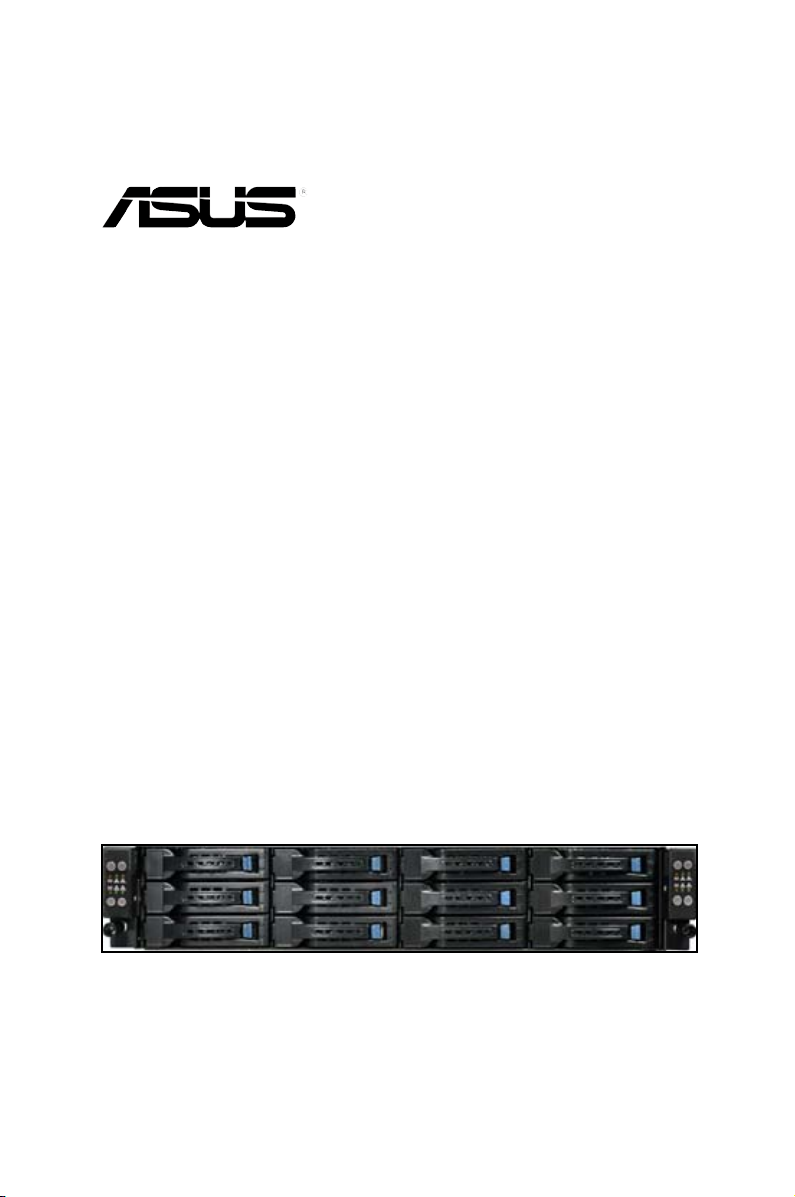
Model Name RS320Q-E7/RS12
Chassis ASUS R21A 2U Rackmount Chassis
Motherboard ASUS P8BH
Component 2 x 920W Redundant Power Supply
Accessories 1 x RS320Q-E7 User’s Guide
Optional Items 1 x PIKE Riser Card (RE16R-R12B-PIKE) per Node
4 x PCIe Riser Card (RE16R-R12B)
2 x Front I/O Board (FPB-R21A)
1 x Redundant Power Supply Distribution Board (PDB-R21A)
1 x SAS/SATA Backplane Board (BP12LX-R21A)
1 x Midplane Board (MP8LX-R21A-M)
1 x Connection Board (CB-R21A)
4 x CPU Heatsink
4 x System Fans (80mm x 38mm)
12 x Hot-swappable 3.5” HDD trays*
1 x RS320Q-E7 Support CD
1 x ASUS ASWM Enterprise User’s Guide
1 x ASUS Web-based Management (ASWM) Enterprise Supplier DVD
1 x Bag of Screws
2 x AC Power Cables
1 x Friction Rail Kit
1 x ASUS PIKE RAID Card per Node
1 x ASMB5-iKVM per Node
• If any of the above items is damaged or missing, contact your retailer.
• * May vary with different regions or territories.
Chapter 1: Product introduction1-2
Page 13
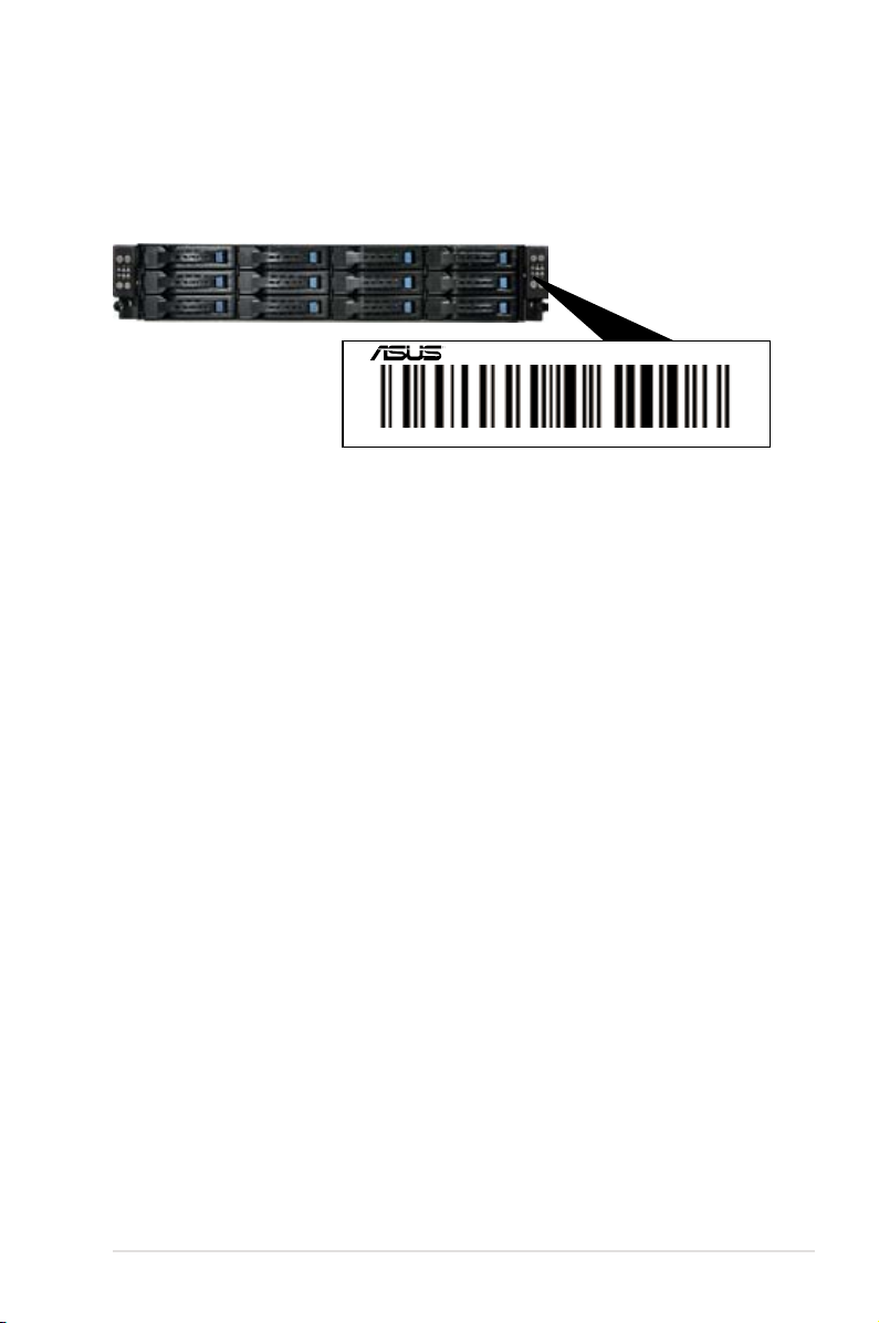
1.2 Serial number label
For faster and quicker troubleshooting solutions from the ASUS Technical Support team,
provide the product's serial number containing 12 characters such as xxS2xxxxxxxx as
shown in the gure below.
RS320Q-E7/RS12
xxS0xxxxxxxxxx
ASUS RS320Q-E7/RS12 1-3
Page 14
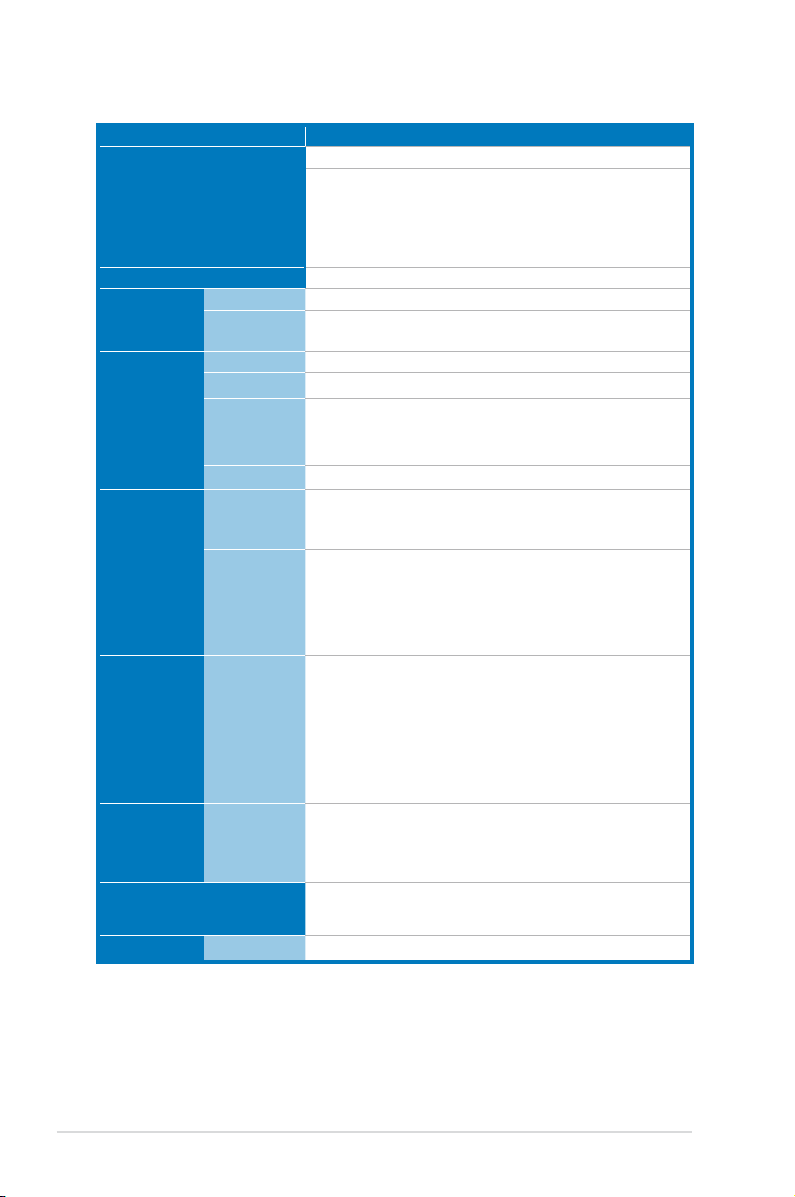
1.3 Systemspecications
Model Name RS320Q-E7/RS12
1 x Socket LGA1155 per Node
Intel® Xeon® E3-1200 v2 processor family
Processor / System Bus
Core Logic
ASUS
Features
Smart Fan
ASWM
Enterprise
Total Slots
Capacity
Memory
Memory Type
Memory Size
Total PCI/
PCI-X/PCI-E
Slots
Expansion
Slots
Slot Type and
Additional
Slot
Storage
SATA
Controller
SAS
Controller
HDD Bays
Networking LAN
Intel® Xeon® E3-1200 processor family
Intel® Core™ i3-2100 processor family
Intel® Pentium™ G6X0 processor family
Intel® Celeron™ G5X0/G4X0 processor family
Intel® C204 Chipset
√
√
4 per Node (2-channel per CPU)
Maximum up to 32GB (UDIMM)
DDR3 1600*/1333/1066 ECC UDIMM
*DDR3 1600 is only supported by Intel® Xeon® E3-1200 v2
processor.
1GB, 2GB, 4GB, 8GB (UDIMM)
1 per Node
1 x *PCI-E 3.0 x16 slot (Gen3 x16 link) (Low prole /
HL) per Node or 1 x *PIKE Riser Card Slot for Storage
Enhancement (Optional)
*Gen3 link is only supported by Intel® Xeon® E3-1200 v2
processor.
Intel® C204:
- 2 x SATA 6Gb/s ports
- 4 x SATA 3Gb/s ports
Intel® Rapid Storage Technology (RST) supports
software RAID 0, 1, 10 & 5 (Windows®)
LSI® MegaRAID driver
- Supports software RAID 0.1 & 10 (Windows® & Linux)
Optional kits(PIKE Riser card is necessary):
ASUS PIKE 2008 8-port SAS 6G RAID card
ASUS PIKE 2008/IMR 8-port SAS2 6G RAID card
ASUS PIKE 2108 8-port SAS2 6G HW RAID card
3 x Hot-swap 3.5” HDD Bays per Node (Total 12 x 3.5”
HDD in 2U)
2 x Intel® 82574L + 1 x Mgmt LAN per Node
(continued on the next page)
Chapter 1: Product introduction1-4
Page 15
Model Name RS320Q-E7/RS12
Graphic VGA
Aspeed AST2050 + 16MB VRAM
Per Node:
- 1 x External serial port
Onboard I/O Connectors
- 3 x RJ-45 ports (one for ASMB5-iKVM)
- 2 x USB 2.0 ports (rear)
- 1 x VGA port
- 1 x Internal A Type USB port
Windows® Server 2008 R2
Windows® Server 2008 R2 Enterprise
Windows® Server 2008 Enterprise 32/64-bit
OS Support
RedHat® Enterprise Linux AS5.6/6 32 / 64-bit
SuSE® Linux Enterprise Server 11.2 32 / 64-bit
CentOS 5.6 32/64-bit
VMWare ESX4.1/ESXi4.1
(Subject to change without any notice)
Out of Band
Management
Solution
Remote
Hardware
Software
Dimension (HH x WW x
DD)
1 x ASMB5-iKVM for KVM-over-IP (Optional)
ASUS ASWM Enterprise
750mm x 444mm x 87mm (2U)
Net Weight Kg (CPU,
DRAM & HDD not
25 Kg
included)
Power Supply
Power Rating
1+1 Redundant 920W 80PLUS Platinum Power Supply
920W: 100-240Vac, 11-4.4A, 50-60Hz Class I
Operating temperature: 10°C–35°C
Environment
Non-operating temperature: -40°C–70°C
Non-operating humidity: 20%–90% ( Non-condensing)
Specications are subject to change without notice.
ASUS RS320Q-E7/RS12 1-5
Page 16
1.4 Front panel features
Front panel
Node 2
Node 1
HDD 1 (Node 1)
HDD 2 (Node 1)
HDD 3 (Node 1)
Refer to section 1.7.1 Front panel LEDs for the LED descriptions.
HDD 1 (Node 2) HDD 1 (Node 3) HDD 1 (Node 4)
HDD 2 (Node 2)
HDD 3 (Node 2)
HDD 2 (Node 3)
1.5 Rear panel features
PSU 2
PSU 1
Node 4
Node 3
HDD 2 (Node 4)
HDD 3 (Node 3)
Front panel
Node 4
Node 3
HDD 3 (Node 4)
Node 2
Node 1
When installing only two nodes, install the nodes to node slot number 1 and 3 or number 2
and 4.
Chapter 1: Product introduction1-6
Page 17
LAN port 2
LAN port 3*
LAN port 1
VGA port
* This port is for ASUS ASMB5-iKVM controller card only.
Serial port
1.6 Internal features
6
4
6
35
USB ports
1
2
ASUS RS320Q-E7/RS12 1-7
Page 18
1. Power supply and power fan
2. ASUS P8BH Server Board
3. System fans
4. SATA/SAS backplane (hidden)
5. Hot-swap HDD trays (SAS and SATA)
6. Front LED Boards
Turn off the system power and detach the power supply before removing or replacing any
system component.
The barebone server does not include a oppy disk drive. Connect a USB oppy disk drive
to any of the USB ports on the front or rear panel if you need to use a oppy disk.
HAZARDOUS MOVING PARTS
WARNING
KEEP FINGERS AND OTHER BODY PARTS AWAY
Chapter 1: Product introduction1-8
Page 19
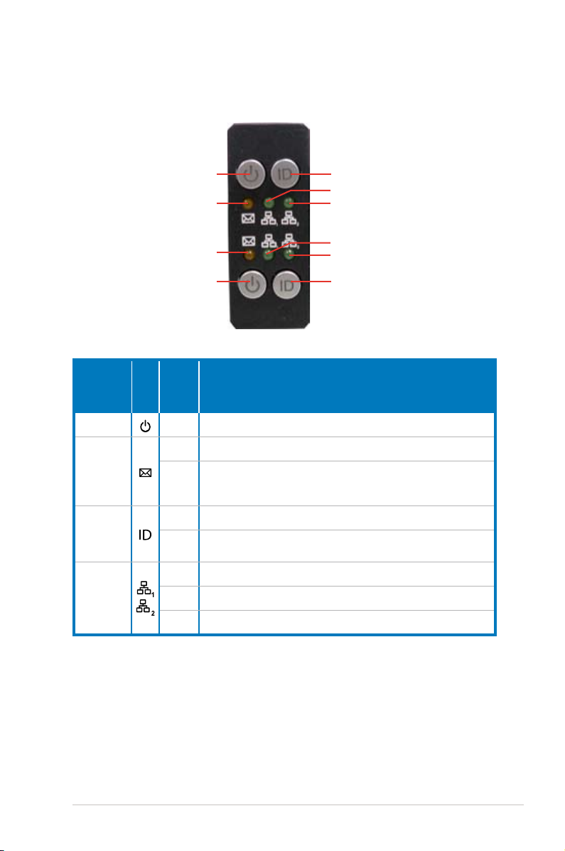
1.7 LED information
1.7.1 Front panel LEDs
Power button and LED
Message LED
Message LED
Power button and LED Location button and LED
LED Icon
Display
status
Description
Location button and LED
LAN1 LED
LAN2 LED
LAN1 LED
LAN2 LED
Power LED ON System power ON
OFF System is normal; no incoming event
Message
LED
1. Without ASMB5-iKVM installed: CPU over-heated
ON
2. With ASMB5-iKVM installed: a hardware monitor event is
indicated
Location
LED
OFF Normal status
Location button is turned on. Press the location button again to
ON
turn off.
OFF No LAN connection
LAN LEDs
Blinking LAN is transmitting or receiving data
ON LAN connection is present
ASUS RS320Q-E7/RS12 1-9
Page 20
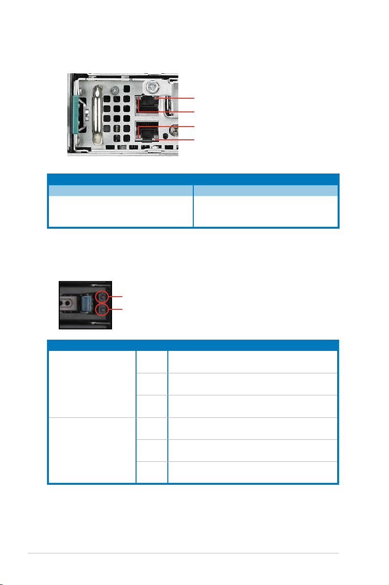
1.7.2 LAN (RJ-45) LEDs
SPEED LED
ACT/LINK LED
ACT/LINK LED
SPEED LED
ACT/LINK LED SPEED LED
Status Description Status Description
OFF No link OFF 10 Mbps connection
GREEN Linked ORANGE 100 Mbps connection
BLINKING Data activity GREEN 1 Gbps connection
1.7.3 HDD status LED
HDD Activity LED (Green)
HDD Status LED (Red)
SATAII/SAS HDD LED Description
OFF HDD not present
HDD Activity LED (Green)
ON HDD present, no activity
Blinking
OFF HDD not present
HDD Status LED (Red)
ON HDD has failed and should be swapped immediately
Blinking
1. Read/write data from/into the SATAII/SAS HDD
2. Locating (blinking with the HDD status LED)
1. RAID rebuilding
2. Locating (blinking with the HDD activity LED)
Chapter 1: Product introduction1-10
Page 21

Chapter 2
This chapter lists the hardware setup
procedures that you have to perform when
installing or removing system components.
Hardware setup
2-
Page 22
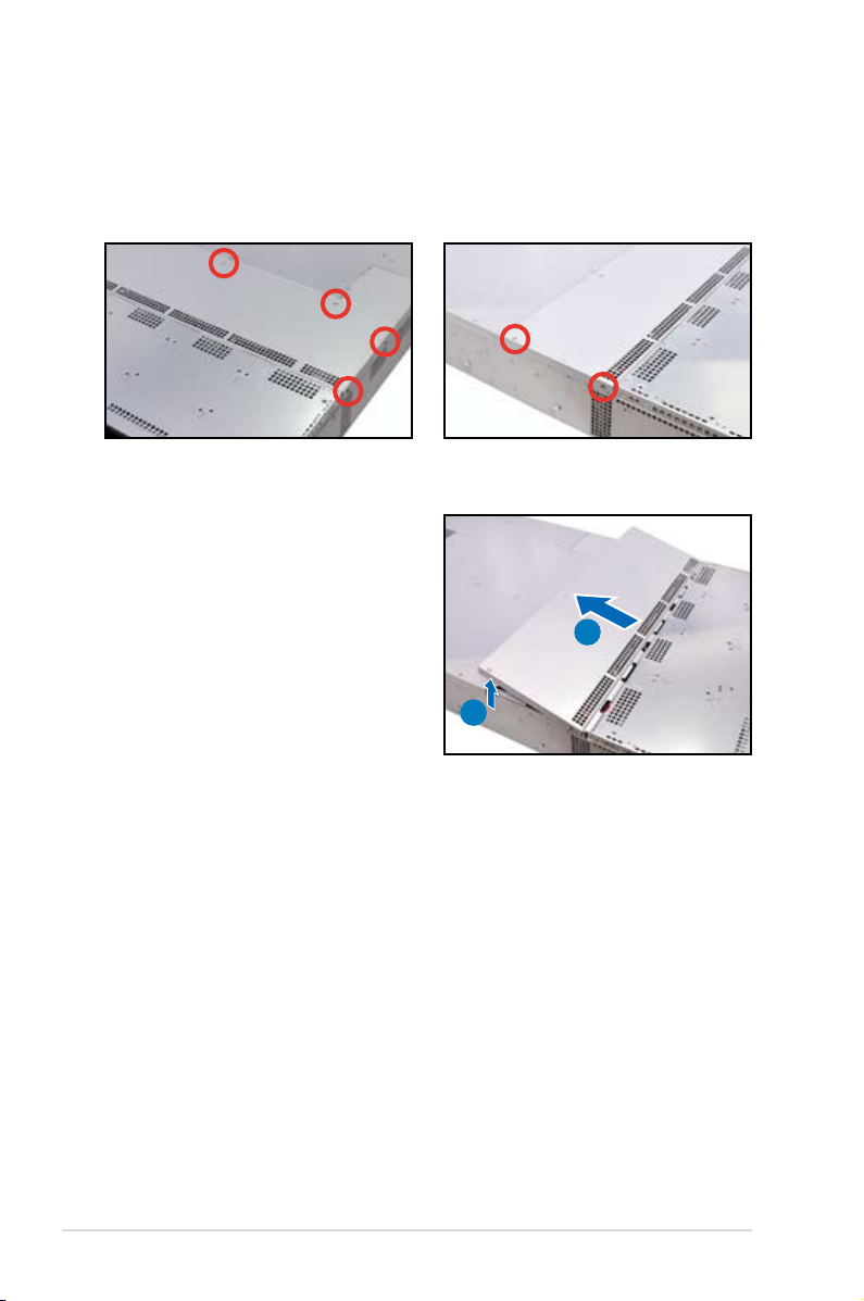
2.1 Chassis cover
Removing the top cover
1. Loosen the six screws on the top and the two sides of the top cover, as shown in the
following gures.
2. Lift the rear end of the top cover (A),
and slide the cover toward the rear
panel (B) until it disengages from the
chassis.
B
A
Chapter 2: Hardware setup2-2
Page 23
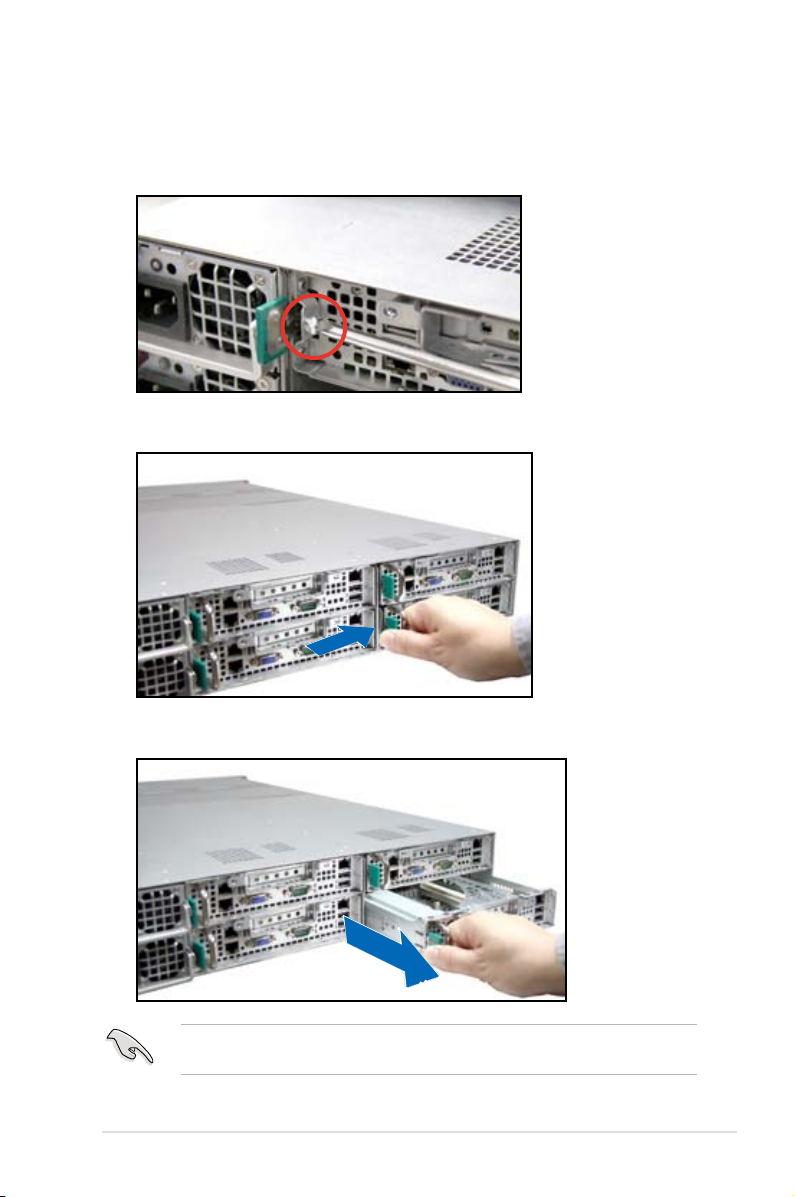
Removing the server node
1. Remove the screw located on the node latch.
2. Hold the server node lever and press the node latch.
3. Firmly pull the server node out of the server chassis.
When installing only two nodes, install the nodes to node slot number 1 and 3 or number 2
and 4. Refer to section
1.5 Rear panel features
for details.
2-3ASUS RS320Q-E7/RS12
Page 24
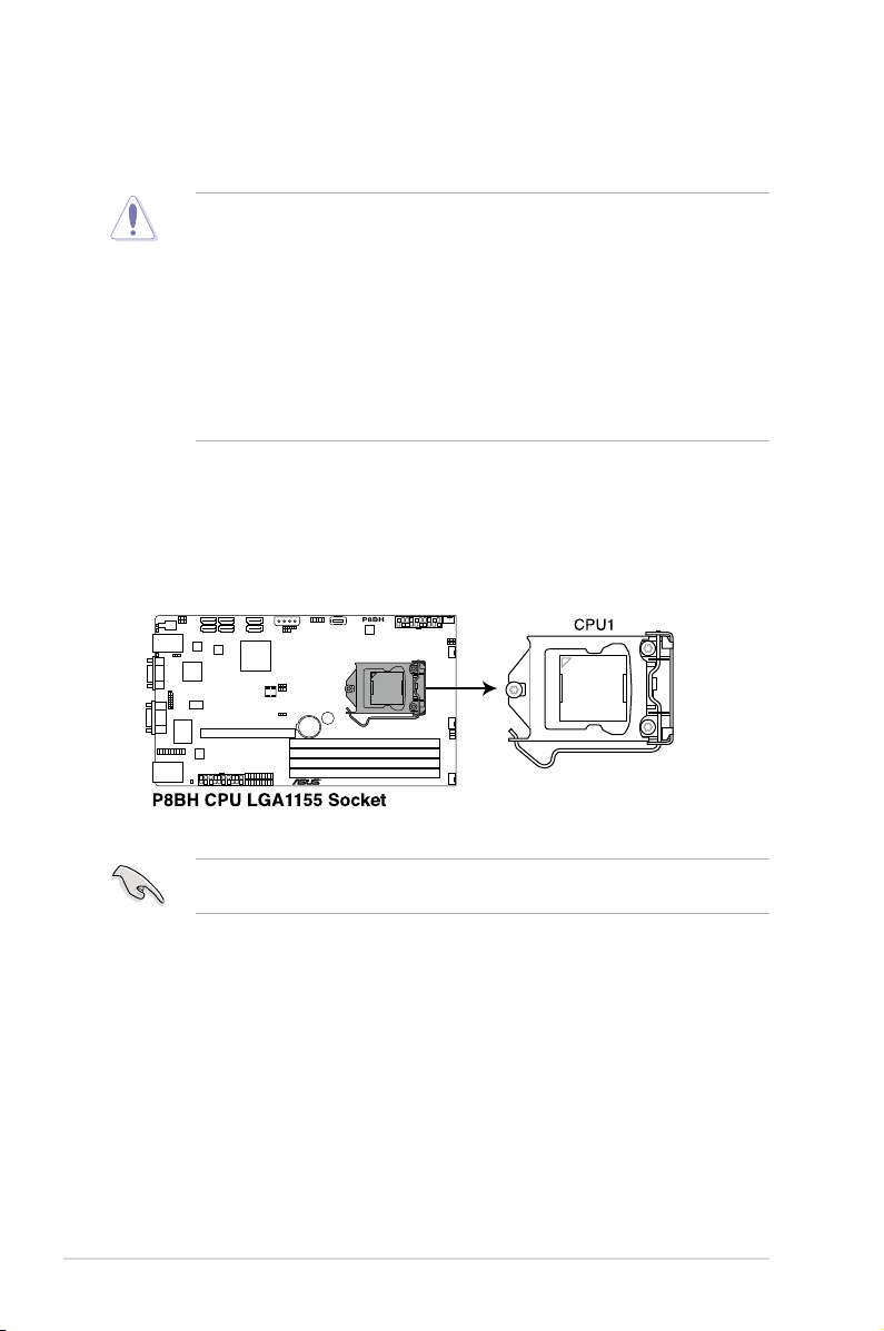
2.2 Central Processing Unit (CPU)
The motherboard comes with a surface mount LGA2011 socket designed for the Intel® Xeon
E5-2600 family processor.
• Upon purchase of the motherboard, ensure that the PnP cap is on the socket and
the socket contacts are not bent. Contact your retailer immediately if the PnP cap
is missing, or if you see any damage to the PnP cap/socket contacts/motherboard
components. ASUS will shoulder the cost of repair only if the damage is shipment/
transit-related.
• Keep the cap after installing the motherboard. ASUS will process Return Merchandise
Authorization (RMA) requests only if the motherboard comes with the cap on the
LGA2011 socket.
• The product warranty does not cover damage to the socket contacts resulting from
incorrect CPU installation/removal, or misplacement/loss/incorrect removal of the PnP
cap.
2.2.1 Installing the CPU
To install a CPU:
1. Locate the CPU socket on the motherboard.
Before installing the CPU, ensure that the socket box is facing toward you and the load lever
is on your left.
Chapter 2: Hardware setup2-4
Page 25
A
B
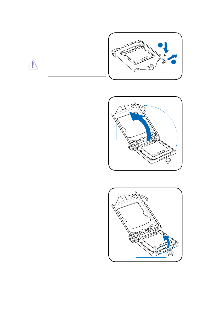
2. Press the load lever with your thumb (A),
and then move it to the right (B) until it is
released from the retention tab.
To prevent damage to the socket pins,
do not remove the PnP cap unless
you are installing a CPU.
3. Lift the load lever in the direction of the
arrow until the load plate is completely
lifted.
Load lever
Retention tab
Load plate
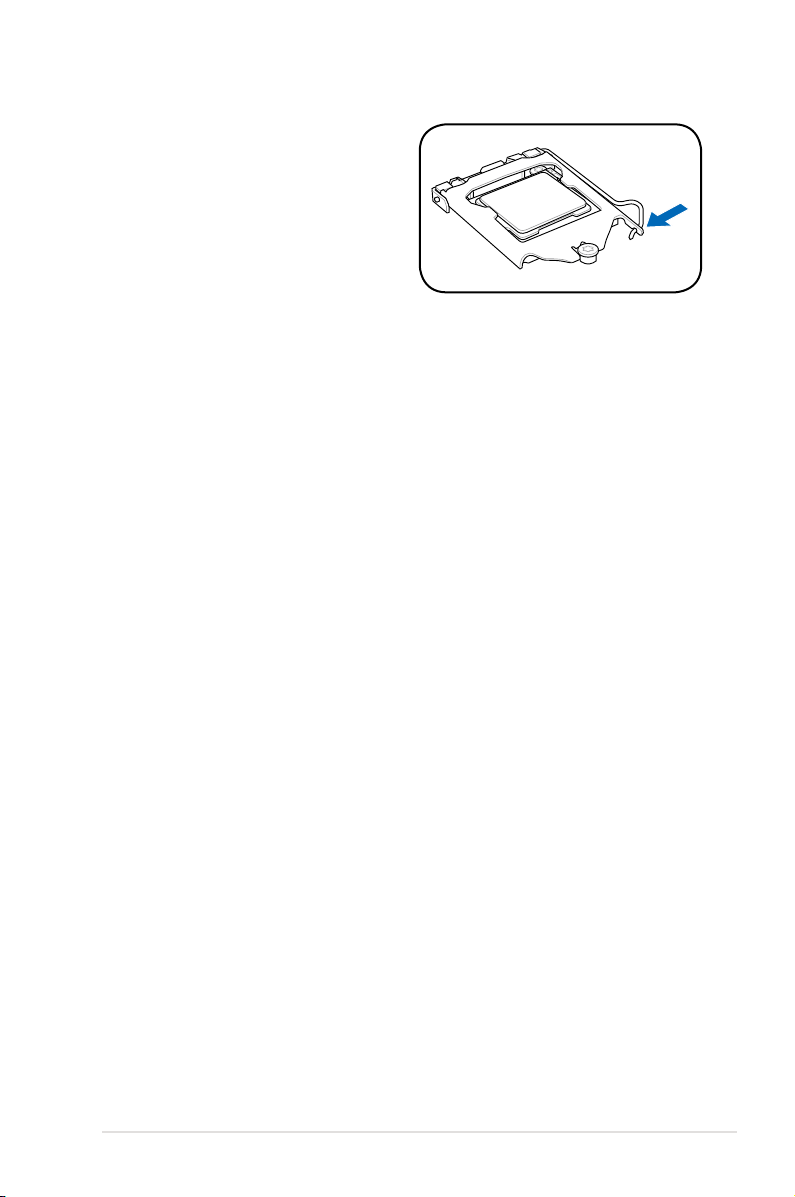
4. Lift the tab only to remove the PnP cap
from the CPU socket.
PnP cap
Cap tab
2-5ASUS RS320Q-E7/RS12
Page 26
C
B
A
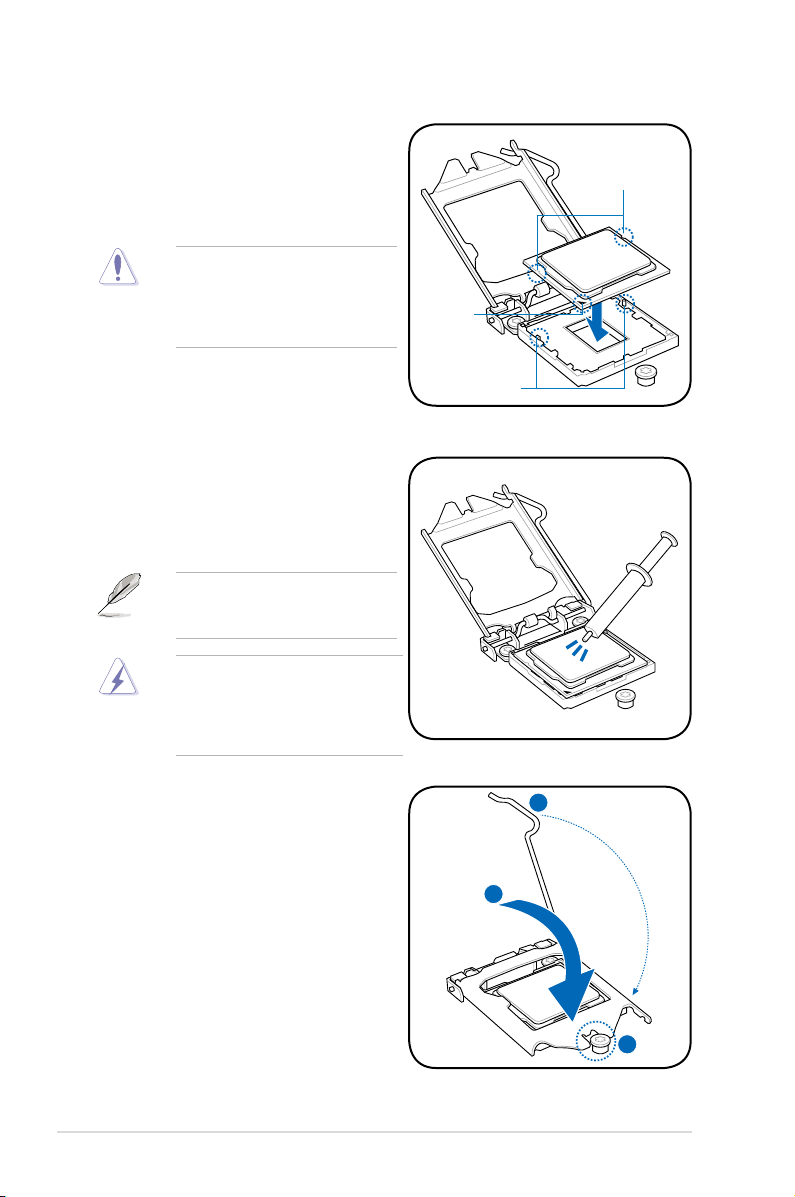
5. Position the CPU over the socket,
ensuring that the gold triangle is on the
bottom-left corner of the socket, and then
t the socket alignment keys into the CPU
notches.
The CPU ts in only one correct
orientation. DO NOT force the CPU
into the socket to prevent bending
the connectors on the socket and
damaging the CPU!
6. Apply some Thermal Interface Material
to the exposed area of the CPU that the
heatsink will be in contact with, ensuring
that it is spread in an even thin layer.
Some heatsinks come with preapplied thermal paste. If so, skip this
step.
The Thermal Interface Material is
toxic and inedible. DO NOT eat it. If
it gets into your eyes or touches your
skin, wash it off immediately, and seek
professional medical help.
CPU notches
Gold
triangle
mark
Alignment keys
7. Close the load plate (A), and then push
down the load lever (B), ensuring that
the front edge of the load plate slides
under the retention knob (C).
Chapter 2: Hardware setup2-6
Page 27
8. Insert the load lever under the retention
tab.
2-7ASUS RS320Q-E7/RS12
Page 28
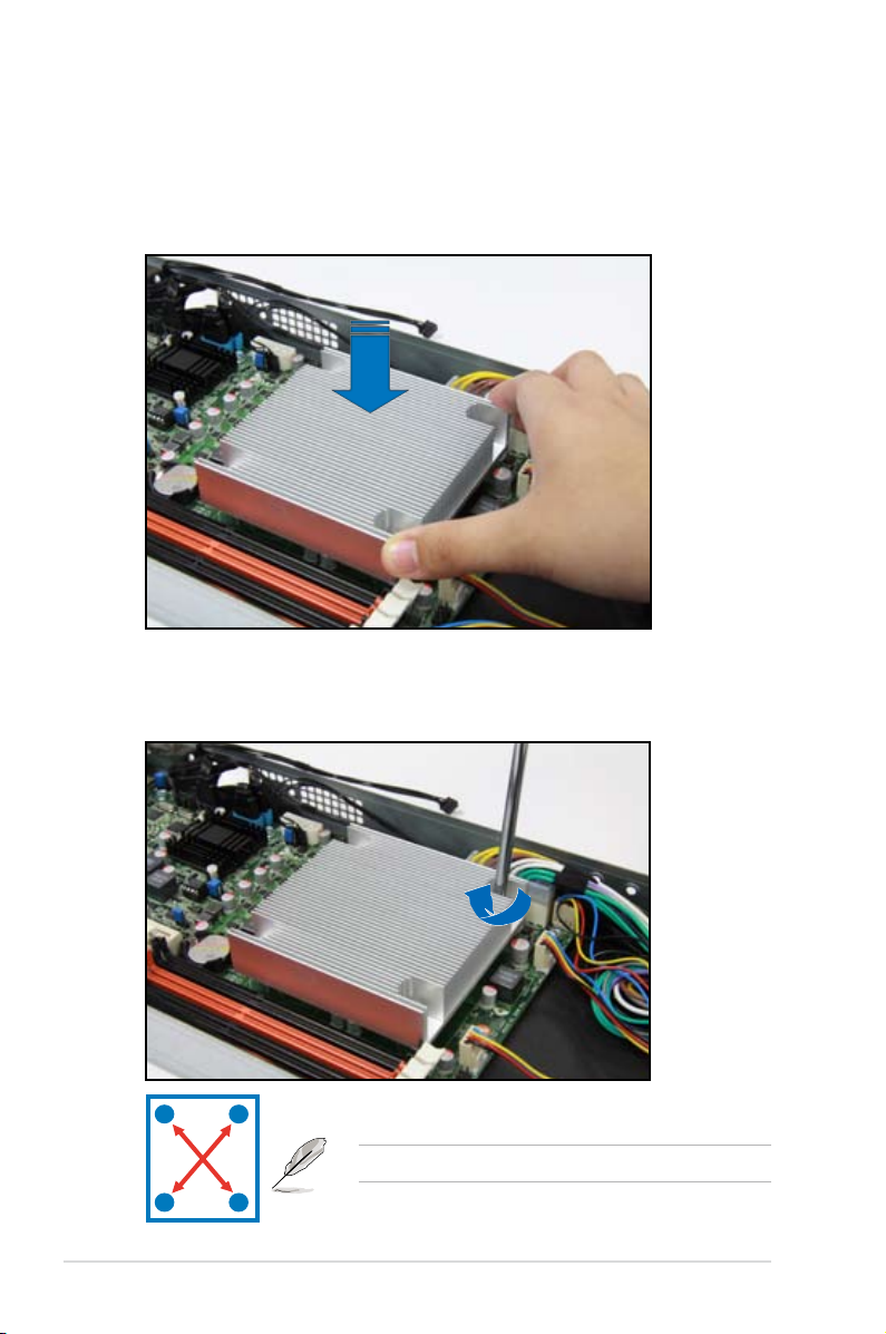
2.2.2 Installing the CPU heatsink
To install the CPU heatsink:
1. Place the heatsink on top of the installed CPU, ensuring that the four fasteners match
the holes on the motherboard.
2. Twist each of the four screws with a Philips (cross) screwdriver just enough to attach
the heatsink to the motherboard. When the four screws are attached, tighten them one
by one to completely secure the heatsink.
A
B
B
Tighten the four heatsink screws in a diagonal sequence.
A
Chapter 2: Hardware setup2-8
Page 29
2.3 System memory
2.3.1 Overview
The motherboard comes with four (4) Double Data Rate 3 (DDR3) Dual Inline Memory Modules
(DIMM) sockets.
The gure illustrates the location of the DDR3 DIMM sockets:
2.3.2 MemoryCongurations
You may install 1 GB, 2 GB, 4 GB, or 8 GB Unbuffered with ECC DDR3 DIMMs into the
DIMM sockets using the memory congurations in this section.
UDIMM
DIMM
Slot Per
Channel
2 1 Unbuffered DDR3 1333/1600* Single Rank, Dual Rank
2 2 Unbuffered DDR3 1333/1600* Single Rank, Dual Rank
DIMM
Populated
per Channel
DIMM Type Speed Rank per DIMM
• *Refer to ASUS Server AVL for latest update.
• Start installing the DIMMs in slots A2 and B2 (orange).
• Always install DIMMs with the same CAS latency. For optimal compatibility, we
recommend that you install memory modules of the same version or data code (D/C)
from the same vendor. Check with the retailer to get the correct memory modules.
2-9ASUS RS320Q-E7/RS12
Page 30
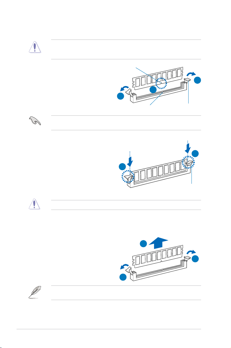
2.3.3 Installing a DIMM
Ensure to unplug the power supply before adding or removing DIMMs or other system
components. Failure to do so may cause severe damage to both the motherboard and the
components.
1. Press the retaining clips outward to
unlock a DIMM socket.
2. Align a DIMM on the socket such that
the notch on the DIMM matches the
DIMM slot key on the socket.
A DIMM is keyed with a notch so that it ts in only one direction. DO NOT force a DIMM into
a socket in the wrong direction to avoid damaging the DIMM.
3. Hold the DIMM by both of its ends,
then insert the DIMM vertically into
the socket. Apply force to both ends
of the DIMM simultaneously until the
retaining clips snap back into place,
and the DIMM cannot be pushed in
any further to ensure proper sitting of
the DIMM.
Always insert the DIMM into the socket VERTICALLY to prevent DIMM notch damage.
2.3.4 Removing a DIMM
DIMM notch
1
3
2
DIMM slot key
Locked Retaining Clip
1
Unlocked retaining clip
3
1. Simultaneously press the retaining
clips outward to unlock the DIMM.
2. Remove the DIMM from the socket.
Support the DIMM lightly with your ngers when pressing the retaining clips. The DIMM
might get damaged when it ips out with extra force.
2
1
1
Chapter 2: Hardware setup2-10
Page 31

2.4 Hard disk drives
The system supports three hot-swap SATAII/SAS hard disk drives per node (available only
when an optional ASUS PIKE SAS RAID card is installed) or three hot-swap SATAII hard disk
drives per node. The hard disk drive installed on the drive tray connects to the motherboard
SATAII/SAS ports via the SATAII/SAS backplane.
To install a hot-swap SATAII/SAS HDD:
1. Push the spring lock to the right, then
pull the tray lever outward to release a
drive tray. The drive tray ejects slightly
after you pull out the lever.
2. Firmly hold the tray lever and pull the
drive tray out of the bay.
spring lock
3. Take note of the drive tray holes. Each
side has three holes to t different types
of hard disk drives. Use two screws on
each side to secure the hard disk drive.
4. Place a SATAII/SAS hard disk drive on
the tray, then secure it with four screws.
2-11ASUS RS320Q-E7/RS12
Page 32

5. Carefully insert the drive tray and push
it all the way to the depth of the bay until
just a small fraction of the tray edge
protrudes.
When installed, the SATAII/SAS connector on the drive connects to the SATAII/SAS
interface on the backplane.
6. Push the tray lever until it clicks, and
secures the drive tray in place. The
drive tray is correctly placed when its
front edge aligns with the bay edge.
7. Repeat steps 1 to 6 if you wish to install
other SATAII/SAS drive(s).
Chapter 2: Hardware setup2-12
Page 33

2.5 Expansion slot
2.5.1 Installing an expansion card to the riser card bracket
The barebone server comes with a riser card bracket. You need to remove the bracket if you
want to install PCI Express x16 expansion cards.
To install a PCI Express x16 card:
1. Remove the three screws on the riser
card bracket.
2. Firmly hold the riser card bracket, and
then pull it up to detach it from the PCI
Express x16 slot on the motherboard.
3. Place the riser card bracket on a at
and stable surface, and then remove
the screw from the slot bay.
4. Install a PCI Express x16 card to the
bracket, and secure the card with a
screw.
PCI Express x16 slot
2-13ASUS RS320Q-E7/RS12
Page 34

5. Press the riser card bracket until the
golden connectors completely t the
slot and the bracket aligns with the rear
panel.
6. Connect the cables to the card, if
applicable.
2.5.2 Conguringanexpansioncard
After installing the expansion card, congure it by adjusting the software settings.
1. Turn on the system and change the necessary BIOS settings, if any. See Chapter 5 for
information on BIOS setup.
2. Assign an IRQ to the card. Refer to the following tables.
3. Install the software drivers for the expansion card.
Standard Interrupt assignments
IRQ Priority Standard function
0 1 System Timer
1 2 Keyboard Controller
2 - Programmable Interrupt
4* 12 Communications Port (COM1)
5* 13 --
6 14 Floppy Disk Controller
7* 15 -8 3 System CMOS/Real Time Clock
9* 4 ACPI Mode when used
10* 5 IRQ Holder for PCI Steering
11* 6 IRQ Holder for PCI Steering
12* 7 PS/2 Compatible Mouse Port
13 8 Numeric Data Processor
14* 9 Primary IDE Channel
15* 10 Secondary IDE Channel
* These IRQs are usually available for ISA or PCI devices.
Chapter 2: Hardware setup2-14
Page 35

2.6 Cable connections
• The bundled system cables are pre-connected before shipment. You do not need to
disconnect these cables unless you will remove pre-installed components to install
additional devices.
• Refer to Chapter 4 for detailed information on the connectors.
P8BH
1
4
3
5
1
2
Pre-connected system cables
1. 20-pin proprietary power connector (from connection board to motherboard)
2. System fan connectors (FRNT_FAN1, FRNT_FAN2, FRNT_FAN3 and FRNT_FAN4)
3. Panel connector (from motherboard to connection board)
4. SATA connectors (from motherboard to SATAII/SAS connection board)
5. Auxiliary panel connector (from motherboard to connection board)
22
2-15ASUS RS320Q-E7/RS12
Page 36

2.7 Removable/optional components
You may need to remove previously installed system components when installing or removing
system devices. You may also need to install the optional components into the system. This
section tells how to remove/install the following components:
1. System fans
2. Power supply module
3. ASUS PIKE RAID card (optional)
4. ASUS ASMB5-iKVM
Ensure that the system is turned off before removing any components.
2.7.1 System fans
To uninstall the system fans:
1. Disconnect the system fan cable
from the fan connector on the HDD
backplane.
2. Lift the fan and set it aside.
3. Repeat steps 1 to 2 to uninstall the
other system fans.
Chapter 2: Hardware setup2-16
Page 37

2.7.2 Power supply module
To install a second power supply module:
1. Press and hold the latch on the dummy
cover and pull out the cover from the
server chassis.
2. Firmly push the second power supply
module into the chassis until the latch
locks to the server chassis.
To replace a failed power supply module:
1. Lift up the power supply module lever.
2. Hold the power supply module lever
and press the PSU latch.
2-17ASUS RS320Q-E7/RS12
Page 38

3. Firmly pull the power supply module out
of the system chassis.
4. Firmly push the new power supply
module into the chassis until the latch
locks to the server chassis.
Chapter 2: Hardware setup2-18
Page 39

2.7.3 Installing ASMB5 series management board
To install the ASMB5 management board:
1. Locate the ASMB5 header on the
motherboard.
2. Orient and press the ASMB5
management card in place.
3. Insert the LAN cable plug to the LAN3
port for server management.
2-19ASUS RS320Q-E7/RS12
Page 40

2.7.4 Installing ASUS PIKE Riser Card (optional)
To install ASUS PIKE riser card:
1. Remove the three screws on the riser
card bracket.
2. Firmly hold the riser card bracket,
and pull it up to detach it from the PCI
Express x16 slot on the motherboard.
3. Locate the two screws on the riser card
bracket, then remove the screws from
the bracket.
4. Locate the two screw holes on the PIKE
riser card.
5. Secure the PIKE riser card to the riser
card bracket with two screws.
Chapter 2: Hardware setup2-20
Page 41

6. Align and insert the golden ngers of
the PIKE SAS RAID card into the card
slot on the PIKE raiser card. Ensure the
card is completely seated on the slot.
7. Locate the SGPIO connector on the
side of the server chassis.
8. Connect the SGPIO cable to the SGPIO
connector on the PIKE Riser card.
9. Remove the SATA/SAS cables from the
onboard SATA1–3 connectors.
2-21ASUS RS320Q-E7/RS12
Page 42

10. Connect the SATA/SAS cables to the
SAS1–3 connectors on the PIKE riser
card.
11. Align the riser card bracket to the PCI
Express x16 slot on the motherboard.
12. Press the riser card bracket until the
golden ngers completely t the slot and
the bracket aligns with the rear panel.
13. Move the
of the server node from pin
1–2 to pin 2–3.
SGPIO_SEL
jumper in front
Chapter 2: Hardware setup2-22
Page 43

Chapter 3
This chapter describes how to install the
optional components and devices into the
barebone server.
Installation options
2-
Page 44

3.1 Installing friction rail kit items
Your friction rail kit package contains:
• One pair of rack rails
• One pair of xing latches
• 4 latch screws, 4 rail screws and 4 rail washers
Rail Washers
Latch screws
Rack railsFixing latchesFront end Rear end
Rail screws
3.1.1 Attachingthexinglatchestotheserver
To attach the xing latches to the server:
1. Remove the two screws on the side of the server chassis.
2. Secure the xing latch with the two screws you removed in step 1.
3. Repeat steps 1 to 2 to secure another xing latch to the other side of the server.
1
2
Chapter 3: Installation options3-2
Page 45

4. Select a 1U space on the rack where
you want to install the rack rail. A
1U space consists of three square
mounting holes with two thin lips on
the top and the bottom.
5. Adjust the rack rail to t the depth of
the rack.
6. From inside the rack, place the rear rail
hook on the bottom thin lip of the rear
mounting hole, and place the front rail hook
on the bottom thin lip of the front mounting
hole.
7. Secure the front and rear ends of the rail
with two rack screws and washers.
8. Repeat steps 4 to 7 to attach the rack rail
on the other side of the rack.
3-3ASUS RS320Q-E7/RS12
Page 46

9. When mounting the server to the rack,
ensure to include the side knots on the two
sides of the server in the rack rail holders.
DO NOT install the rail kit in the situations shown below:
DO NOT place the rail hook on a thick lip
of the mounting hole.
DO NOT install the rail to the outer side of
the server rack.
Chapter 3: Installation options3-4
Page 47

3.1.2 Mounting the server to the rack
To mount the server to the rack:
1. Place the server on the rack rails, and push the server all the way to the depth of the
rack.
2. Tighten the two rack screws to secure
the server in place.
To uninstall the server from the rack:
1. Loosen the rack screws that secured the server to the rack.
2. Pull the server from the rack.
Remember to press the latches on
both sides to release the server from
the rack.
3-5ASUS RS320Q-E7/RS12
Page 48

Chapter 3: Installation options3-6
Page 49

Chapter 4
This chapter includes the motherboard
layout, and brief descriptions of the jumpers
and internal connectors.
Motherboard info
3-
4-1
Page 50

4.1 Motherboard layouts
P8BH
20
17
18
19
3
16
14
5
21
23
22
6
9
4
8
13
17
10
7
1
2
17
12
12 12
4-2 Chapter 4: Motherboard information
15
12
11
Page 51

Layout contents
Connectors/Jumpers/Buttons and Switches/Slots Page
1. CPU socket 2-4
2. DDR3 sockets
3. PCI Express x16 slot
4. Clear RTC RAM (CLRTC1)
5. VGA controller setting (3-pin VGA_SW1)
6. LAN controller setting (3-pin LAN_SW1, LAN_SW2)
7. RAID conguration utility selection (3-pin RAID_SEL1)
8. ME rmware force recovery setting (3-pin ME_RECOVERY1)
9. Serial ATA connectors (SATA 6Gb/s: 7-pin SATA1, SATA2 [Blue])
(SATA 3Gb/s: 7-pin SATA3, SATA4, SATA5, SATA6 [Black])
10. USB connector (10-1 pin USB34, USB56; A-Type USB5)
11. Thermal sensor cable connectors (3-pin TR1, TR2)
Front fan connectors (FRNT_FAN1, FRNT_FAN2, FRNT_FAN3,
12.
FRNT_FAN4)
13. Serial General Purpose Input/Output connector (6-1 pin SGPIO1)
14. BMC header (BMC_FW1)
15. Power Supply SMBus connector (5-pin PSUSMB1)
16. TPM connector (20-1-pin TPM)
17. Proprietary power connectors (20-pin PWR1, 20-pin PWR2,
4-pin PWR3)
18. System panel connector (20-1 pin PANEL1)
19. Auxiliary panel connector (20-2 pin AUX_PANEL1)
20. Standby Power LED (SB_PWR1)
21. Baseboard Management Controller LED (BMC_LED1)
22. P8BH +5 Power LED (+5V_LED)
23. Location LED (LOC_LED)
2-9
2-13
4-4
4-5
4-5
4-6
4-6
4-7
4-7
4-8
4-8
4-9
4-9
4-10
4-10
4-11
4-12
4-13
4-14
4-14
4-15
4-15
ASUS RS320Q-E7/RS12 4-3
Page 52

4.2 Jumpers
1. Clear RTC RAM (CLRTC1)
This jumper allows you to clear the Real Time Clock (RTC) RAM in CMOS. You can
clear the CMOS memory of date, time, and system setup parameters by erasing
the CMOS RTC RAM data. The onboard button cell battery powers the RAM data in
CMOS, which include system setup information such as system passwords.
To erase the RTC RAM:
1. Turn OFF the computer and unplug the power cord.
2. Move the jumper cap from pins 1–2 (default) to pins 2–3. Keep the cap on pins 2–3
for about 5–10 seconds, then move the cap back to pins 1–2.
3. Plug the power cord and turn ON the computer.
4. Hold down the <Del> key during the boot process and enter BIOS setup to re-enter
data.
Except when clearing the RTC RAM, never remove the cap on CLRTC jumper default position.
Removing the cap will cause system boot failure!
If the steps above do not help, remove the onboard battery and move the jumper again to clear
the CMOS RTC RAM data. After the CMOS clearance, reinstall the battery.
4-4 Chapter 4: Motherboard information
Page 53

2. VGA controller setting (3-pin VGA_SW1)
This jumper allows you to enable or disable the onboard VGA controller. Set to pins 1–2
to activate the VGA feature.
3. LAN controller setting (3-pin LAN_SW1, LAN_SW2)
These jumpers allow you to enable or disable the onboard Intel® Intel 82574LGigabit LAN
controllers. Set to pins 1–2 to activate the Gigabit LAN feature.
ASUS RS320Q-E7/RS12 4-5
Page 54

4. RAIDcongurationutilityselection(3-pinRAID_SEL1)
This jumper allows you to select the RAID conguration utility to use when you create
disk arrays. Place the jumper caps over pins 1–2 if you want to use the LSI Logic
Embedded SATA RAID Setup Utility (default). Otherwise, place the jumper caps to pins
2–3 to use the Intel® Rapid Storage Technology.
5. MErmwareforcerecoverysetting(3-pinME_RECOVERY1)
This jumper allows you to quickly recover the Intel Management Engine (ME) rmware
when it becomes corrupted.
4-6 Chapter 4: Motherboard information
Page 55

4.3 Internal connectors
1. Serial ATA connectors (SATA 6Gb/s: 7-pin SATA1, SATA2 [Blue]) (SATA 3Gb/s:
7-pin SATA3, SATA4, SATA5, SATA6 [Black])
Supported by the Intel® C204 chipset, these connectors are for the Serial ATA signal
cables for Serial ATA hard disk drives that allows up to 6Gb/s of data transfer rate.
If you installed Serial ATA hard disk drives, you can create a RAID 0, RAID 1, RAID 10,
or RAID 5 conguration.
The actual data transfer rate depends on the speed of Serial ATA hard disks installed.
For details on the Intel® Rapid Storage Technology utility, please refer to Chapter 6 RAID
Conguration.
2. USB connector (10-1 pin USB34, USB56; A-Type USB5)
These connectors are for USB 2.0 ports. Connect the USB module cables to
connectors USB34, then install the modules to a slot opening at the back of the system
chassis. These USB connectors comply with USB 2.0 specication that supports up to
480 Mbps connection speed.
ASUS RS320Q-E7/RS12 4-7
Page 56

3. Thermal sensor cable connectors (3-pin TR1/TR2)
This connector is for temperature monitoring. Connect the thermal sensor cable
to this connector and place the other end to the device, which you want to monitor
temperature.
4. Front fan connectors (FRNT_FAN1, FRNT_FAN2, FRNT_FAN3, FRNT_FAN4)
The fan connectors support cooling fans of 350 mA–740 mA (8.88 W max.) or a total of
3.15 A–6.66 A (53.28 W max.) at +12V. Connect the fan cables to the fan connectors
on the motherboard, ensuring that the black wire of each cable matches the ground pin
of the connector.
• DO NOT forget to connect the fan cables to the fan connectors. Insufcient air ow
inside the system may damage the motherboard components.
• These are not jumpers! DO NOT place jumper caps on the fan connectors!
• All fans feature the ASUS Smart Fan technology.
4-8 Chapter 4: Motherboard information
Page 57

5. Serial General Purpose Input/Output connector (6-1 pin SGPIO1)
This connector is used for the SGPIO peripherals for the Intel Rapid Storage
Technology RAID SATA LED and LSI MegaRAID.
6. BMC header (BMC_FW1)
The BMC connector on the motherboard supports an ASUS
Board 5 Series (ASMB5).
®
Server Management
ASUS RS320Q-E7/RS12 4-9
Page 58

7. Power Supply SMBus connector (5-pin PSUSMB1)
This connector allows you to connect SMBus (System Management Bus) to the power
supply unit to read PSU information. Devices communicate with an SMBus host and/or
other SMBus devices using the SMBus interface.
This connector functions only when you install the ASUS ASMB5.
8. TPM connector (20-1 pin TPM)
This connector supports a Trusted Platform Module (TPM) system, which can securely
store keys, digital certicates, passwords, and data. A TPM system also helps enhance
network security, protects digital identities, and ensures platform integrity.
4-10 Chapter 4: Motherboard information
Page 59

9. Proprietary power connectors (20-pin PWR1, 20-pin PWR2, 4-pin PWR3)
These connectors are for Proprietary power supply plugs. The power supply plugs are
designed to t these connectors in only one orientation. Orient the connectors and
push down rmly until they completely t.
The 4-pin EZ_PLUG is designed for hard disk drives power supply. DO NOT connect
other 4-pin power connectors of the power supply unit (PSU) to this connector.
• Connect either one of the 20-pin power connectors to boot up the system.
• Use of a PSU with a higher power output is recommended when conguring a system
with more power-consuming devices. The system may become unstable or may not
boot up if the power is inadequate.
• USE THE PROPRIETARY POWER SUPPLY ONLY; otherwise you may damage the
motherboard. Ensure that your PSU can provide at least the minimum power required
by your system.
ASUS RS320Q-E7/RS12 4-11
Page 60

10. System panel connector (20-pin PANEL1)
This connector supports several chassis-mounted functions.
1. System power LED (3-pin PLED)
This 3-pin connector is for the system power LED. Connect the chassis power
LED cable to this connector. The system power LED lights up when you turn on
the system power, and blinks when the system is in sleep mode.
2. Message LED (2-pin MLED)
This 2-pin connector is for the message LED cable that connects to the front
message LED. The message LED is controlled by Hardware monitor to indicate
an abnormal event occurrence.
3. System warning speaker (4-pin SPEAKER)
This 4-pin connector is for the chassis-mounted system warning speaker. The
speaker allows you to hear system beeps and warnings.
4. Hard disk drive activity LED (2-pin HDDLED)
This 2-pin connector is for the HDD Activity LED. Connect the HDD Activity LED
cable to this connector. The IDE LED lights up or ashes when data is read from
or written to the HDD.
5. Power button/soft-off button (2-pin PWRSW)
This connector is for the system power button. Pressing the power button turns
the system on or puts the system in sleep or soft-off mode depending on the
BIOS settings. Pressing the power switch for more than four seconds while the
system is ON turns the system OFF.
6. Reset button (2-pin RESET)
This 2-pin connector is for the chassis-mounted reset button for system reboot
without turning off the system power.
4-12 Chapter 4: Motherboard information
Page 61

11. Auxiliary panel connector (20-pin AUX_PANEL1)
This connector is for additional front panel features including front panel SMB, locator
LED and switch, chassis intrusion, and LAN LEDs.
1. Front panel SMB (6-1 pin FPSMB)
These leads connect the front panel SMBus cable.
2. LAN activity LED (2-pin LAN1_LED, LAN2_LED
These leads are for Gigabit LAN activity LEDs on the front panel.
3. Chassis intrusion (4-1 pin CHASSIS)
These leads are for the intrusion detection feature for chassis with intrusion
sensor or microswitch. When you remove any chassis component, the sensor
triggers and sends a high-level signal to these leads to record a chassis intrusion
event. The default setting is short CASEOPEN and GND pin by jumper cap to
disable the function.
4. Locator LED (2-pin LOCATORLED1 and 2-pin LOCATORLED2)
These leads are for the locator LED1 and LED2 on the front panel. Connect the
Locator LED cables to these 2-pin connector. The LEDs will light up when the
Locator button is pressed.
5. Locator Button/Switch (2-pin LOCATORBTN)
These leads are for the locator button on the front panel. This button queries the
state of the system locator.
)
ASUS RS320Q-E7/RS12 4-13
Page 62

4.4 Internal LEDs
1. Standby Power LED (SB_PWR1)
The motherboard comes with a standby power LED. The green LED lights up to
indicate that the system is ON, in sleep mode, or in soft-off mode. This is a reminder
that you should shut down the system and unplug the power cable before removing or
plugging in any motherboard component.
2. Baseboard Management Controller LED (BMC_LED1)
The green heartbeat LED blinks per second to indicate that the ASMB5 is working
normally.
The heartbeat LED functions only when you install the ASUS ASMB5.
4-14 Chapter 4: Motherboard information
Page 63

3. P8BH +5V Power LED (+5V_LED)
This LED lights up when you turn on the system using the Power-on button.
4. Location LED (LOC_LED)
This LED lights up for you to conveniently locate the system in error.
ASUS RS320Q-E7/RS12 4-15
Page 64

4-16 Chapter 4: Motherboard information
Page 65

Chapter 5
This chapter tells how to change
the system settings through the BIOS Setup
menus. Detailed descriptions of the BIOS
parameters are also provided.
BIOS setup
3-
Page 66

5.1 Managing and updating your BIOS
The following utilities allow you to manage and update the motherboard Basic Input/Output
System (BIOS) setup:
ASUS CrashFree BIOS 3 (To recover the BIOS using a bootable USB ash disk drive
1.
when the BIOS le fails or gets corrupted.)
2.
ASUS EZ Flash 2 (Updates the BIOS using a USB ash disk.)
3.
BUPDATER utility (Updates the BIOS in DOS mode using a bootable USB ash disk
drive.)
Refer to the corresponding sections for details on these utilities.
Save a copy of the original motherboard BIOS le to a bootable USB ash disk drive
in case you need to restore the BIOS in the future. Copy the original motherboard BIOS
using the BUPDATER utility.
5.1.1 ASUS CrashFree BIOS 3 utility
The ASUS CrashFree BIOS 3 is an auto recovery tool that allows you to restore the BIOS le
when it fails or gets corrupted during the updating process. You can update a corrupted BIOS
le using a USB ash drive that contains the updated BIOS le.
Prepare a USB ash drive containing the updated motherboard BIOS before using this
utility.
RecoveringtheBIOSfromaUSBashdrive
To recover the BIOS from a USB ash drive:
1. Insert the USB ash drive with the original or updated BIOS le to one USB port on the
system.
2. The utility will automatically recover the BIOS. It resets the system when the BIOS
recovery nished.
DO NOT shut down or reset the system while recovering the BIOS! Doing so would cause
system boot failure!
The recovered BIOS may not be the latest BIOS version for this motherboard. Visit the
ASUS website at www.asus.com to download the latest BIOS le.
5-2 Chapter 5: BIOS setup
Page 67

5.1.2 ASUS EZ Flash Utility
The ASUS EZ Flash Utility feature allows you to update the BIOS without having to use a
DOS-based utility.
Before you start using this utility, download the latest BIOS from the ASUS website at www.
asus.com.
To update the BIOS using EZ Flash Utility:
1. Insert the USB ash disk that contains the latest BIOS le to the USB port.
2. Enter the BIOS setup program. Go to the
and press <Enter> to enable it.
ASUSTek EZ Flash BIOS ROM Utility V00.75
Flash Info
MODEL: P8BH VER: 0303 DATE: 02/17/2012
fs0:\
Drive Folder Info
fs0:\ 02/17/12 10:23p 4194304 P8BH.CAP
fs1:\
File Infor
MODEL: VER: DATE:
Help Info
Tool menu to select ASUS EZ Flash Utility
Exit
[Enter] Select or Load [Tab] Switch [Up/Down/PageUp/PageDown/Home/End] Move [Esc] Exit [F2] Backup
3. Press <Tab> to switch to the Drive eld.
4. Press the Up/Down arrow keys to nd the USB ash disk that contains the latest BIOS,
and then press <Enter>.
5. Press <Tab> to switch to the
Folder Info eld.
6. Press the Up/Down arrow keys to nd the BIOS le, and then press <Enter> to perform
the BIOS update process. Reboot the system when the update process is done.
5-3ASUS RS320Q-E7/RS12
Page 68

• This function can support devices such as a USB ash disk with FAT 32/16 format and
single partition only.
• DO NOT shut down or reset the system while updating the BIOS to prevent system
boot failure!
Ensure to load the BIOS default settings to ensure system compatibility and stability. Press
<F5> and select Yes to load the BIOS default settings.
5.1.3 BUPDATER utility
The succeeding BIOS screens are for reference only. The actual BIOS screen displays may
not be the same as shown.
The BUPDATER utility allows you to update the BIOS le in DOS environment using a
bootable USB ash disk drive with the updated BIOS le.
UpdatingtheBIOSle
To update the BIOS le using the BUPDATER utility:
1. Visit the ASUS website at www.asus.com and download the latest BIOS le for the
motherboard. Save the BIOS le to a bootable USB ash disk drive.
2. Copy the BUPDATER utility (BUPDATER.exe) from the ASUS support website at
support.asus.com to the bootable USB ash disk drive you created earlier.
3. Boot the system in DOS mode, then at the prompt, type:
BUPDATER /i[lename].ROM
where [lename] is the latest or the original BIOS le on the bootable USB ash disk
drive, then press <Enter>.
A:\>BUPDATER /i[le name].ROM
5-4 Chapter 5: BIOS setup
Page 69

4. The utility veries the le, then starts updating the BIOS le.
ASUSTek BIOS Update for DOS V1.06 (09/08/04)
FLASH TYPE: MXIC 25L1605A
Current ROM
BOARD: P8BH
VER: 0201
DATE: 03/10/2012
PATH:
WARNING! Do not turn off power during ash BIOS
Note
Writing BIOS:
Update ROM
BOARD: P8BH
VER: 0202
DATE: 03/10/2012
DO NOT shut down or reset the system while updating the BIOS to prevent system boot
failure!
5. The utility returns to the DOS prompt after the BIOS update process is completed.
Reboot the system from the hard disk drive.
The BIOS update is nished! Please restart your system.
C:\>
5-5ASUS RS320Q-E7/RS12
Page 70

5.2 BIOS setup program
This motherboard supports a programmable rmware chip that you can update using the
provided utility described in section 5.1 Managing and updating your BIOS.
Use the BIOS Setup program when you are installing a motherboard, reconguring your
system, or prompted to “Run Setup.” This section explains how to congure your system
using this utility.
Even if you are not prompted to use the Setup program, you can change the conguration of
your computer in the future. For example, you can enable the security password feature or
change the power management settings. This requires you to recongure your system using
the BIOS Setup program so that the computer can recognize these changes and record them
in the CMOS RAM of the rmware chip.
The rmware chip on the motherboard stores the Setup utility. When you start up the
computer, the system provides you with the opportunity to run this program. Press <Del>
during the Power-On Self-Test (POST) to enter the Setup utility; otherwise, POST continues
with its test routines.
If you wish to enter Setup after POST, restart the system by pressing <Ctrl+Alt+Delete>, or by
pressing the reset button on the system chassis. You can also restart by turning the system
off and then back on. Do this last option only if the rst two failed.
The Setup program is designed to make it as easy to use as possible. Being a menu-driven
program, it lets you scroll through the various sub-menus and make your selections from the
available options using the navigation keys.
• The default BIOS settings for this motherboard apply for most conditions to ensure
optimum performance. If the system becomes unstable after changing any BIOS
settings, load the default settings to ensure system compatibility and stability. Press
<F5> and select Yes to load the BIOS default settings.
• The BIOS setup screens shown in this section are for reference purposes only, and
may not exactly match what you see on your screen.
• Visit the ASUS website (www.asus.com) to download the latest BIOS le for this
motherboard.
5-6 Chapter 5: BIOS setup
Page 71

5.2.1 BIOS menu screen
Menu items
Aptio Setup Utility - Copyright (C) 2012 American Megatrends, Inc.
Main Event Logs Advanced Monitor Boot Tool Exit
BIOS Information
BIOS Version 0303 x64
Build Date 03/10/2012
CPU Information
Intel(R) Xeon(R) CPU E31230 @ 3.20GHz
Memory Information
Total Memory 1024 MB
System Date [Fri 02/17/2012]
System Time [15:07:28]
Access Level Administrator
Security
Version 2.01.1204. Copyright (C) 2012 American Megatrends, Inc.
Submenu item
Menu bar
Congurationelds
Set the Date, Use Tab to
switch between Data elements.
→←: Select Screen
↑↓: Select Item
Enter: Select Item
+/-: Change Opt.
F1: General Help
F2: Previous Values
F5: Optimized Defaults
F10: Save & Exit
ESC: Exit
5.2.2 Menu bar
The menu bar on top of the screen has the following main items:
General help
Navigation keys
Main For changing the basic system conguration
Advanced For changing the advanced system settings
Server Mgmt For changing the Server Mgmt settings
Event Logs For changing the event log settings
Monitor For displaying the system temperature, power status, and changing
the fan settings
Security For changing the security settings
Boot For changing the system boot conguration
Tool For conguring options for special functions
Exit For selecting the exit options
To select an item on the menu bar, press the right or left arrow key on the keyboard until the
desired item is highlighted.
5-7ASUS RS320Q-E7/RS12
Page 72

5.2.3 Menu items
The highlighted item on the menu bar displays the specic items for that menu. For example,
selecting Main shows the Main menu items.
The other items (Event Logs, Advanced, Monitor, Boot, Tool, and Exit) on the menu bar have
their respective menu items.
5.2.4 Submenu items
A solid triangle before each item on any menu screen means that the item has a submenu. To
display the submenu, select the item and press <Enter>.
5.2.5 Navigation keys
At the bottom right corner of a menu screen are the navigation keys for the BIOS setup
program. Use the navigation keys to select items in the menu and change the settings.
5.2.6 General help
At the top right corner of the menu screen is a brief description of the selected item.
5.2.7 Congurationelds
These elds show the values for the menu items. If an item is user-congurable, you can
change the value of the eld opposite the item. You cannot select an item that is not usercongurable.
A congurable eld is enclosed in brackets, and is highlighted when selected. To change the
value of a eld, select it and press <Enter> to display a list of options.
5.2.8 Pop-up window
Select a menu item and press <Enter> to display a pop-up window with the conguration
options for that item.
5.2.9 Scroll bar
A scroll bar appears on the right side of a menu screen when there are items that do not t on
the screen. Press the Up/Down arrow keys or <Page Up> /<Page Down> keys to display the
other items on the screen.
5-8 Chapter 5: BIOS setup
Page 73

5.3 Main menu
When you enter the BIOS Setup program, the Main menu screen appears. The Main menu
provides you an overview of the basic system information, and allows you to set the system
date, time settings.
Aptio Setup Utility - Copyright (C) 2012 American Megatrends, Inc.
Main Event Logs Advanced Monitor Boot Tool Exit
BIOS Information
BIOS Version 0303 x64
Build Date 03/10/2012
CPU Information
Intel(R) Xeon(R) CPU E31230 @ 3.20GHz
Memory Information
Total Memory 1024 MB
System Date [Sat 03/10/2012]
System Time [15:07:28]
Access Level Administrator
Security
5.3.1 System Date [Day xx/xx/xxxx]
Allows you to set the system date.
5.3.2 System Time [xx:xx:xx]
Allows you to set the system time.
5.3.3 Security
The Security menu items allow you to change the system security settings.
Set the Date, Use Tab to
switch between Data elements.
Aptio Setup Utility - Copyright (C) 2012 American Megatrends, Inc.
Main Event Logs Advanced Monitor Boot Tool Exit
Password Description
If ONLY the Administrator's password is set,
then this only limits access to Setup and is
only asked for when entering Setup
If ONLY the User's password is set, then this
is a power on password and must be entered to
boot or enter Setup. In Setup the User will
have Administrator rights
Administrator Password Not Installed
User Password Not Installed
Administrator Password
User Password
Set Setup Administrator
Password
• If you have forgotten your BIOS password, erase the CMOS Real Time Clock (RTC)
RAM to clear the BIOS password. See section 2.6 Jumpers for information on how to
erase the RTC RAM.
Administrator or User Password items on top of the screen show the default
• The
Not Installed. After you set a password, these items show Installed.
5-9ASUS RS320Q-E7/RS12
Page 74

Administrator Password
If you have set an administrator password, we recommend that you enter the administrator
password for accessing the system. Otherwise, you might be able to see or change only
selected elds in the BIOS setup program.
To set an administrator password:
1. Select the
2. From the
3. Conrm the password when prompted.
To change an administrator password:
1. Select the
2. From the
<Enter>.
3. From the
4. Conrm the password when prompted.
To clear the administrator password, follow the same steps as in changing an administrator
password, but press <Enter> when prompted to create/conrm the password. After you clear
the password, the Administrator Password item on top of the screen shows Not Installed.
Administrator Password item and press <Enter>.
Create New Password box, key in a password, then press <Enter>.
Administrator Password item and press <Enter>.
Enter Current Password box, key in the current password, then press
Create New Password box, key in a new password, then press <Enter>.
User Password
If you have set a user password, you must enter the user password for accessing the system.
The User Password item on top of the screen shows the default Not Installed. After you set
a password, this item shows Installed.
To set a user password:
1. Select the
2. From the
3. Conrm the password when prompted.
To change a user password:
1. Select the
2. From the
<Enter>.
3. From the
4. Conrm the password when prompted.
To clear the user password, follow the same steps as in changing a user password, but press
<Enter> when prompted to create/conrm the password. After you clear the password, the
User Password item on top of the screen shows Not Installed.
User Password item and press <Enter>.
Create New Password box, key in a password, then press <Enter>.
User Password item and press <Enter>.
Enter Current Password box, key in the current password, then press
Create New Password box, key in a new password, then press <Enter>.
5-10 Chapter 5: BIOS setup
Page 75

5.4 Event Logs menu
The Event Logs menu items allow you to change the event log settings and view the system
event logs.
Aptio Setup Utility - Copyright (C) 2012 American Megatrends, Inc.
Main Event Logs Advanced Monitor Boot Tool Exit
Change Smbios Event Log Settings
View Smbios Event Log
View System Event Log
Change Smbios Event Log Settings
Aptio Setup Utility - Copyright (C) 2012 American Megatrends, Inc.
Main Event Logs Advanced Monitor Boot Tool Exit
Enabling/Disabling Options
Smbios Event Log [Enabled]
Erasing Settings
Erase Event Log [No]
When Log is Full [Do Nothing]
Smbios Event Log Standard Settings
Log System Boot Event [Disabled]
MECI 1
METW 60
Custom Options
Log OEM Codes [Enabled]
Convert OEM Codes [Disabled]
NOTE: All values changed here do not take effect
until computer is restarted.
Smbios Event Log [Enabled]
Allows you to enable or disable all features of Smbios event logging.
Conguration option: [Disabled] [Enabled]
Erase Event Log [No]
Allows you to select the options for erasing Smbios event log.
Conguration options: [No] [Yes, Next reset] [Yes, Every reset]
When Log is Full [Do Nothing]
Allows you to select the options for reaction when the event logs are full.
Conguration options: [Do Nothing] [Erase Immediately]
Log System Boot Event [Disabled]
Allows you to enable or disable logging system boot event.
Conguration options: [Enabled] [Disabled]
MECI [xx]
Allows you to adjust value for the MECI (Multiple Event Count Increment) using the <+>
and <-> keys.
Press <Enter> to change the
Smbios Event Log conguration.
Change this to enable or
disable all features of Smbios
Event Logging during boot.
5-11ASUS RS320Q-E7/RS12
Page 76

METW [xx]
Allows you to adjust value for the METW (Multiple Event Time Window) using
the <+> and <-> keys.
Log OEM Codes [Enabled]
Allows you to enable or disable the logging of EFI status codes as OEM codes.
Conguration option: [Disabled] [Enabled]
Convert OEM Codes [Disabled]
Allows you to enable or disable the converting of EFI status codes to standard Smbios
types.
Conguration option: [Disabled] [Enabled]
View Smbios Event Log
Press <Enter> to view the Smbios event logs.
View System Event Log
Press <Enter> to view the system event logs.
5-12 Chapter 5: BIOS setup
Page 77

5.5 Advanced menu
The Advanced menu items allow you to change the settings for the CPU and other system
devices.
Take caution when changing the settings of the Advanced menu items. Incorrect eld
values can cause the system to malfunction.
Aptio Setup Utility - Copyright (C) 2012 American Megatrends, Inc.
Main Event Logs Advanced Monitor Boot Tool Exit
ACPI Settings
Trusted Computing
WHEA Conguration
CPU Conguration
North Bridge
South Bridge
SATA Conguration
Intel TXT(LT) Conguration
USB Conguration
ME Subsystem
Onboard Devices Conguration
APM
Serial Port Console Redirection
5.5.1 ACPI Settings
Aptio Setup Utility - Copyright (C) 2012 American Megatrends, Inc.
Advanced
ACPI Settings
Enable ACPI Auto Conguration [Disabled]
ACPI Sleep State [S3 (Suspend to RAM)]
System ACPI Parameters
Enables or Disables BIOS ACPI
Auto Conguration.
EnableACPIAutoConguration[Disabled]
Allows you to enable or disable ACPI Auto Conguration.
Conguration options: [Disabled] [Enabled]
ACPI Sleep State [S3 (Suspend to RAM)]
Allows you to set the ACPI Sleep State.
Conguration options: [Suspend Disabled] [S1 (CPU Stop Clock)] [S3 (Suspend to RAM)]
5-13ASUS RS320Q-E7/RS12
Page 78

5.5.2 Trusted Computing
Aptio Setup Utility - Copyright (C) 2012 American Megatrends, Inc.
Advanced
TPM Conguration
TPM SUPPORT [Enabled]
Current TPM Status Information
NO TPM Hardware
Enables or Disables TPM
support. O.S. will not show
TPM. Reset of platform is
required.
TPM SUPPORT [Enabled]
Allows you to enable or disable the TPM support.
Conguration options: [Disabled] [Enabled]
5.5.3 WHEA Support
Aptio Setup Utility - Copyright (C) 2012 American Megatrends, Inc.
Advanced
WHEA Support [Enabled]
Enable or disable Windows
Hardware Error Architecture.
WHEA [Enabled]
Allows you to enable or disable the Windows Hardware Error Architecture support.
Conguration options: [Disabled] [Enabled]
5-14 Chapter 5: BIOS setup
Page 79

5.5.4 CPUConguration
The items in this menu show the CPU-related information that the BIOS automatically
detects. Some items may not appear if your CPU does not support the related functions.
Aptio Setup Utility - Copyright (C) 2012 American Megatrends, Inc.
Advanced
CPU Conguration
Intel(R) Xeon(R) CPU E31230 @ 3.20GHz
EM64T Supported
Processor Speed 3200 MHz
CPUID 206a7
L1 Data Cache 32 kB x 4
L1 Code Cache 32 kB x 4
L2 Cache 256 kB x 4
L3 Cache 8192 KB
Processor Cores 4
Intel HT Technology Supported
CPU Current Ratio 33
Active Processor Cores [All]
Limit CPUID Maximum [Disabled]
Execute Disable Bit [Enabled]
Enhanced Intel SpeedStep Technolog [Enabled]
Turbo Mode [Enabled]
CPU C1E [Enabled]
CPU C3 Report [Enabled]
CPU C6 Report [Enabled]
Package C State Limit [No Limit]
Intel Virtualization Technology [Enabled]
Version 2.01.1204. Copyright (C) 2010 American Megatrends, Inc.
Includes TM1, TM2 and EMTTM
→←: Select Screen
↑↓: Select Item
Enter: Select Item
+/-: Change Opt.
F1: General Help
F2: Previous Values
F5: Optimized Defaults
F10: Save & Exit
ESC: Exit
Active Processor Cores [All]
Allows you to choose the number of CPU cores to activate in each processor package.
Conguration options: [All] [1] [2] [3]
Limit CPUID Maximum [Disabled]
Setting this item to [Enabled] allows legacy operating systems to boot even without support
for CPUs with extended CPUID functions.
Conguration options: [Disabled] [Enabled]
Execute Disable Bit [Enabled]
Allows you to enable or disable the No-Execution Page Protection Technology. Setting this
item to [Disabled] forces the XD feature ag to always return to zero (0).
Conguration options: [Disabled] [Enabled]
5-15ASUS RS320Q-E7/RS12
Page 80

Enhanced Intel SpeedStep Technology [Enabled]
Allows you to enable or disable the Enhanced Intel® SpeedStep Technology (EIST).
Conguration options: [Disabled] [Enabled]
Turbo Mode [Enabled]
This item appears only when you set the
[Enabled] and allows you to enable or disable the Intel® Turbo Mode Technology.
Conguration options: [Disabled] [Enabled]
Enhanced Intel SpeedStep Technology
item to
CPU C1E [Enabled]
[Enabled] Enables the C1E support function. This item should be enabled in order to
[Disabled] Disables this function.
enable the Enhanced Halt State.
CPU C3 Report [Enabled]
Allows you to disable or enable the CPU C3 report to OS.
CPU C6 Report [Enabled]
Allows you to disable or enable the CPU C6 report to OS.
Package C State Limit [No Limit]
Conguration options: [No Limit] [C0] [C1] [C3] [C6]
Intel Virtualization Tech [Enabled]
The Intel® Virtualization Technology allows a hardware platform to run multiple operating
systems separately and simultaneously, enabling one system to virtually function as several
systems.
Conguration options: [Disabled] [Enabled]
5-16 Chapter 5: BIOS setup
Page 81

5.5.5 North Bridge
The North Bridge is built in the CPU.
Aptio Setup Utility - Copyright (C) 2012 American Megatrends, Inc.
Advanced
Memory Information
TOTAL Memory 1024 MB
DIMM_A1 Not Present
DIMM_A0 1024 MB (DDR3 1333)
DIMM_B1 Not Present
DIMM_B2 Not Present
VT-d [Enabled]
VT-d [Enabled]
Allows you to enable or disable the VT-d on MCH.
Conguration options: [Disabled] [Enabled]
5.5.6 South Bridge
Aptio Setup Utility - Copyright (C) 2012 American Megatrends, Inc.
Advanced
SB Chipset Conguration
High Precision Event Timer Conguration
High Precision Timer [Enabled]
Check to enable VT-d function
on MCH.
Enabled/disabled the High
Precision Event Timer.
High Precision Timer [Enabled]
Allows you to enable or disable the High Precision Event Timer.
Conguration options: [Enabled] [Disabled]
5-17ASUS RS320Q-E7/RS12
Page 82

5.5.7 SATAConguration
While entering Setup, the BIOS automatically detects the presence of SATA devices. The
SATA Port items show
Not Present
if no SATA device is installed to the corresponding SATA
port.
Aptio Setup Utility - Copyright (C) 2012 American Megatrends, Inc.
Advanced
SATA Conguration
SATA Mode [IDE Mode]
S.M.A.R.T. Status Check [Enabled]
SATA Port1 ST3160812AS (160.0GB)
SATA Port2 ST3160812AS (160.0GB)
SATA Port3 ASUS CB-521 ATAPI
SATA Port4 Not Present
SATA Port5 Not Present
SATA Port6 Not Present
(1) IDE Mode. (2) AHCI Mode.
(3) RAID Mode.
SATA Mode [IDE Mode]
Allows you to set the SATA conguration.
Conguration options: [Disabled] [IDE Mode] [AHCI Mode] [RAID Mode]
• If you want to use the Serial ATA hard disk drives as Parallel ATA physical storage
devices, keep the default setting [IDE Mode].
• If you want the Serial ATA hard disk drives to use the Advanced Host Controller
Interface (AHCI), set this item to [AHCI Mode]. The AHCI allows the onboard storage
driver to enable advanced Serial ATA features that increases storage performance on
random workloads by allowing the drive to internally optimize the order of commands.
• If you want to create RAID sets with LSI MegaRAID utility, or Intel
Technology from the Serial ATA hard disk drives, set this item to [RAID Mode].
®
Matrix Storage
S.M.A.R.T. Status Check [Enabled]
S.M.A.R.T. (Self-Monitoring, Analysis and Reporting Technology) is a monitor system. When
read/write of your hard disk errors occur, this feature allows the hard disk to report warning
messages during the POST.
Conguration options: [Enabled] [Disabled]
5-18 Chapter 5: BIOS setup
Page 83

5.5.8 IntelTXT(LT)Conguration
Aptio Setup Utility - Copyright (C) 2012 American Megatrends, Inc.
Advanced
Intel Trusted Execution Technology Conguration
Intel TXT support only can be enabled/disabled if
SMX is enabled. VT and VT-d support must also be
enabled prior to TXT.
Secure Mode Extensions (SMX) Enabled
Intel TXT(LT) Support [Disabled]
Enables or Disables Intel(R)
TXT(LT) support.
Intel TXT(LT) Support [Disabled]
Allows you to enable or disable support for Intel Trusted Execution Technology (TXTLT).
Conguration options: [Disabled] [Enabled]
5.5.9 USBConguration
The North Bridge is built in the CPU.
Aptio Setup Utility - Copyright (C) 2012 American Megatrends, Inc.
Advanced
USB Conguration
USB Devices
1 Mouse, 2 Hubs
Legacy USB Support [Enabled]
EHCI Hand-off [Disabled]
USB hardware delays and time-out:
USB transfer time-out [20 sec]
Device reset time-out [20 sec]
Device power-up delay [Auto]
Enables Legacy USB support.
AUTO option disables legacy
support if no USB devices are
connected. DISABLE option will
keep USB devices available
only for EFI applications.
The
USB Devices
item shows
item shows the auto-detected values. If no USB device is detected, the
.
None
Legacy USB Support [Enabled]
Allows you to enable or disable support for legacy USB devices. Setting to [Auto] allows the
system to detect the presence of USB devices at startup. If detected, the USB controller
legacy mode is enabled. If no USB device is detected, the legacy USB support is disabled.
Conguration options: [Disabled] [Enabled] [Auto]
EHCI Hand-off [Disabled]
Enables or disables the BIOS EHCI hand-off support.
Conguration options: [Disabled] [Enabled]
5-19ASUS RS320Q-E7/RS12
Page 84

USB transfer time-out [20 sec]
Allows you to select the USB transfer time-out value.
Conguration options: [1 sec] [5 sec] [10 sec] [20 sec]
Device reset time-out [20 sec]
Allows you to select the USB device reset time-out value.
Conguration options: [10 sec] [20 sec] [30 sec] [40 sec]
Device power-up delay [Auto]
Conguration options: [Auto] [Manual]
5.5.10 ME Subsystem
Aptio Setup Utility - Copyright (C) 2012 American Megatrends, Inc.
Advanced
Intel ME Subsystem Conguration
ME Subsystem [Enabled]
ME BIOS Interface Version 2.0
ME Version 2.2.0.42
ME FW Status Value : 0xf0345
ME FW State : SPS ME FW Active
ME FW Operation State : MO without UMA
ME FW Error Code : No Error
ME Ext FW Status Value: Performance Optimized
Cores Disabled : 0
ME FW SKU Information : SiEn
ME Subsystem Help
ME Subsystem [Enabled]
Allows you to enable or disable the Intel Management Engine (Intel ME) Subsystem that
performs various tasks while the system is in sleep, during the boot process and when the
system is running.
Conguration options: [Enabled] [Disabled]
5-20 Chapter 5: BIOS setup
Page 85

5.5.11 OnboardDevicesConguration
The Onboard Devices Conguration menu items allow you to change the advanced settings
for onboard devices.
Aptio Setup Utility - Copyright (C) 2012 American Megatrends, Inc.
Advanced
INTEL W82574L OpROM1 [PXE]
INTEL W82574L OpROM2 [PXE]
Serial Port 1 Conguration
Serial Port 2 Conguration
Launch Intel PXE OpROM
INTEL W82574L OpROM1/OpROM2 [PXE]
Allows you to select the options for the OptionRom of the Intel LAN controllers.
Conguration options: [Disabled] [PXE] [iSCSI]
SerialPort1/2Conguration
The sub-items in this menu allow you to set the serial port 1/2 conguration.
Serial Port [Enabled]
Allows you to enable or disable the serial port (COM).
Conguration options: [Enabled] [Disabled]
Change Settings [Auto]
Allows you to select the serial port base address.
Conguration options: [Auto] [IO=3F8h; IRQ=4] [IO=3F8h: IRQ=3, 4, 5, 6, 7, 9, 10, 11,
12] [IO=2F8h; IRQ=3, 4, 5, 6, 7, 9, 10, 11, 12] [IO=3E8h; IRQ=3, 4, 5, 6, 7, 9, 10, 11,
12] [IO=2E8h; IRQ=3, 4, 5, 6, 7, 9, 10, 11, 12]
5-21ASUS RS320Q-E7/RS12
Page 86

5.5.12 APM
Aptio Setup Utility - Copyright (C) 2012 American Megatrends, Inc.
Advanced
EuP Ready [Disabled]
Restrore AC Power Loss [Power Off]
Power On By PCIE [Disabled]
Power On By Ring [Disabled]
Power On By RTC [Disabled]
Specify what state to go to
when power is re-applied after
a power failure (G3 state).
EuP Ready [Disabled]
When set to [Enabled], all other PME options will be switched off.
Conguration options: [Disabled] [Enabled]
Restore AC Power Loss [Power Off]
When set to [Power Off], the system goes into off state after an AC power loss. When set
to [Power On], the system will reboot after an AC power loss. When set to [Last State], the
system goes into either off or on state, whatever the system state was before the AC power
loss.
Conguration options: [Power Off] [Power On] [Last State]
Power On By PCIE [Disabled]
[Disabled] Disables the PCIE devices to generate a wake event.
[Enabled] Enables the PCIE devices to generate a wake event.
Power On By Ring [Disabled]
[Disabled] Disables Ring to generate a wake event.
[Enabled] Enables Ring to generate a wake event.
Power On By RTC [Disabled]
[Disabled] Disables RTC to generate a wake event.
[Enabled] When set to [Enabled], the items
Minute/Second will become user-congurable with set values.
5-22 Chapter 5: BIOS setup
RTC Alarm Date (Days) and Hour/
Page 87

5.5.13 Serial Port Console Redirection
Aptio Setup Utility - Copyright (C) 2012 American Megatrends, Inc.
Advanced
Redirection After BIOS POST [Disabled]
COM1
Console Redirection [Disabled]
Console Redirection Settings
COM2
Console Redirection [Enabled]
Console Redirection Settings
Serial Port for Out-of-Band Management/
Windows Emergency Management Services (EMS)
Console Redirection [Disabled]
Console Redirection Settings
Console Redirection Enable
or Disable.
Redirection After BIOS POST [Disable]
Enables or disables the redirection after BIOS POST feature.
Conguration options: [Disabled] [Enabled]
COM1 / COM2 Console Redirection [Disabled]
Enables or disables the console redirection feature.
Conguration options: [Disabled] [Enabled]
The Console Redirection Settings becomes congurable when Console Redirection is
set to [Enabled].
COM1 / COM2 Console Redirection Settings
The settings specify how the host computer and the remote computer (which the user is
using) will exchange data. Both computers should have the same or compatible settings.
Terminal Type [VT-UTF8]
Allows you to set the terminal type.
[VT100] ASCII char set.
[VT100+] Extends VT100 to support color, function keys, etc.
[VT-UTF8] Uses UTF8 encoding to map Unicode chars onto 1 or more bytes
[ANSI] Extended ASCII char set
5-23ASUS RS320Q-E7/RS12
Page 88

Bits per second [57600]
Selects serial port transmission speed. The speed must be matched on the other side.
Long or noisy lines may require lower speeds.
Conguration options: [9600] [19200] [38400] [57600] [115200]
Data Bits [8]
Conguration options: [7] [8]
Parity [None]
A parity bit can be sent with the data bits to detect some transmission errors. [Mark]
and [Space] parity do not allow for error detection.
[Even] parity bit is 0 if the num of 1’s in the data bits is even
[Odd] parity bit is 0 if num of 1’s in the data bits is odd
[Mark] parity bit is always 1
[Space] parity bit is always 0
Stop Bits [1]
Version 2.14.1219. Copyright (C) 2011 American Megatrends, Inc.
Stop bits indicate the end of a serial data packet. (A start bit indicates the beginning.)
The standard setting is 1 stop bit. Communication with slow devices may require more
than 1 stop bit.
Conguration options: [1] [2]
Flow Control [None]
Flow control can prevent data loss from buffer overow. When sending data, if the
receiving buffers are full, a “stop” signal can be sent to stop the data ow. Once the
buffers are empty, a “start” signal can be sent to re-start the ow. Hardware ow control
uses two wires to send start/stop signals.
Conguration options: [None] [Hardware RTS/CTS]
VT-UTF8 Combo Key Support [Enabled]
Allows you to enable and disable the VT-UTF8 combination key support for ANSI/
VT100 terminals.
Conguration options: [Enabled] [Disabled]
Recorder Mode [Disabled]
With this mode enabled only text will be sent. This is to capture Terminal data.
Conguration options: [Disabled] [Enabled]
Resolution 100x31 [Enabled]
Allows you to enable or disable the extended terminal resolution.
Conguration options: [Enabled] [Disabled]
Legacy OS Redirection Resolution
Congures the number of rows and columns supported on legacy OS.
Conguration options: [80x24] [80x25]
5-24 Chapter 5: BIOS setup
Page 89

5.6 Monitor menu
The Monitor menu displays the system temperature/power status, and allows you to change
the fan settings.
Aptio Setup Utility - Copyright (C) 2012 American Megatrends, Inc.
Main Event Logs Advanced Monitor Boot Tool Exit
CPU Temperature(PECI) [ +35ºC/ +94ºF]
TR1 Temperature [ +35ºC/ +94ºF]
TR2 Temperature [ N/A ]
FRNT FAN1 Speed [ N/A ]
FRNT FAN2 Speed [ N/A ]
FRNT FAN3 Speed [ N/A ]
FRNT FAN4 Speed [ N/A ]
FAN Speed Control [Generic Mode]
VCORE1 [ +1.200 V ]
+3.3V [ +3.360 V ]
+5V [ +5.160 V ]
+12V [ +12.384 V ]
VBAT [ +3.408 V ]
+3VSB [ +3.422 V ]
+1.5V [ +1.496 V ]
CPU/TR2/TR1 Temperature [xxxºC/xxxºF]
The onboard hardware monitor automatically detects and displays the CPU and motherboard
component temperatures. Select Ignore if you do not wish to display the detected
temperatures.
FRNT FAN1–4 Speed [xxxx RPM] or [Ignore] / [N/A]
The onboard hardware monitor automatically detects and displays the speed of CPU fans,
front fans, and rear fan in rotations per minute (RPM). If the fan is not connected to the
motherboard, the eld shows
Fan Speed Control [Generic Mode]
Allows you to congure the ASUS Smart Fan feature that smartly adjusts the fan speeds for
more efcient system operation.
Conguration options: [Full Speed Mode] [High Density Mode] [Generic Mode] [Whisper
Mode]
N/A
.
VCORE1 Voltage, 3.3V Voltage, +5V Voltage, +12V Voltage, VBAT
Voltage, +3VSB Voltage, +1.5V ICHVoltage
The onboard hardware monitor automatically detects the voltage output through the onboard
voltage regulators. Select
if you do not want to detect this item.
Ignore
5-25ASUS RS320Q-E7/RS12
Page 90

5.7 Boot menu
The Boot menu items allow you to change the system boot options.
Aptio Setup Utility - Copyright (C) 2012 American Megatrends, Inc.
Main Event Logs Advanced Monitor Boot Tool Exit
Number of seconds to wait for
Setup Prompt Timeout 5
Bootup NumLock State [On]
Full Screen Logo [Enabled]
Option ROM Messages [Force BIOS]
INT19 Trap Response [Enabled]
Boot Device Seeking [Endless PXE]
Load RT32 Image [Enalbed]
CSM Support [Enabled]
UEFI Boot [Disabled]
Boot Option Priorities
Boot Option #1 [IBA GE Slot 0200 v...]
Boot Override
IBA GE Slot 0400 v1356
IBA GE Slot 0500 v1356
Network Device BBS Priorities
Setup Prompt Timeout [xx]
Use the <+> and <-> keys to adjust the number of seconds to wait for setup activation key.
Bootup NumLock State [On]
Allows you to select the power-on state for the NumLock.
Conguration options: [Off] [On]
Full Screen Logo [Enabled]
Allows you to enable or disable the full screen logo display feature.
Conguration options: [Disabled] [Enabled]
setup activation key.
65535(0xFFFF) means indenite
waiting.
Set this item to [Enabled] to use the ASUS MyLogo2™ feature.
Option ROM Messages [Force BIOS]
Allows you to set the display mode for Options ROM.
Conguration options: [Force BIOS] [Keep Current]
INT19 Trap Response [Immediate]
Allows you to execute the trap response by Options ROM.
Conguration options: [Immediate] [Postponed]
Boot Device Seeking [Endless PXE]
[Endless PXE] Continuous seek remote boot image until boot image found or user abort
[Normal] Seek remote boot image.
5-26 Chapter 5: BIOS setup
(press Ctrl+Alt+Del).
Page 91

CSM Support [Disabled]
Enables or disables the CSM Support.
Conguration options: [Disabled] [Enabled] [Auto]
UEFI Boot [Disabled]
Enables or disables the UEFI Boot.
Coniguration options: [Disabled] [Enabled]
Boot Option Priorities
These items specify the boot device priority sequence from the available devices. The number
of device items that appears on the screen depends on the number of devices installed in the
system.
• To select the boot device during system startup, press <F8> when ASUS Logo
appears.
• To access Windows OS in Safe Mode, do any of the following:
- Press <F5> when ASUS Logo appears.
- Press <F8> after POST.
Boot Override
These items displays the available devices. The number of device items that appears on
the screen depends on the number of devices installed in the system. Click an item to start
booting from the selected device.
5-27ASUS RS320Q-E7/RS12
Page 92

5.8 Tool menu
The Tool menu items allow you to congure options for special functions. Select an item then
press <Enter> to display the submenu.
Aptio Setup Utility - Copyright (C) 2012 American Megatrends, Inc.
Main Event Logs Advanced Monitor Boot Tool Exit
ASUS EZ Flash Utility
ASUS EZ Flash Utility
Allows you to run ASUS EZ Flash 2. When you press <Enter>. Check section 5.1.2 ASUS EZ
Flash 2 utility for details.
Be used to update BIOS
5-28 Chapter 5: BIOS setup
Page 93

5.9 Exit menu
The Exit menu items allow you to save or discard your changes to the BIOS items.
Aptio Setup Utility - Copyright (C) 2012 American Megatrends, Inc.
Main Event Logs Advanced Monitor Boot Tool Exit
Save Changes & Reset
Discard Changes & Exit
Launch EFI Shell from lesystem device
Pressing <Esc> does not immediately exit this menu. Select one of the options from this
menu or <F10> from the legend bar to exit.
Save Changes & Reset
Once you are nished making your selections, choose this option from the Exit menu to
ensure the values you selected are saved. When you select this option or if you press <F10>,
a conrmation window appears. Select
to save changes and exit.
Yes
Discard Changes & Exit
This option allows you to exit the Setup program without saving your changes. When you
select this option or if you press <Esc>, a conrmation window appears. Select
changes and exit.
LaunchEFIShellfromlesystemdevice
This option allows you to attempt to launch the EFI Shell application (shellx64.e) from one of
the available lesystem devices.
Reset the system after saving
the changes.
to discard
Yes
5-29ASUS RS320Q-E7/RS12
Page 94

5-30 Chapter 5: BIOS setup
Page 95

Chapter 6
This chapter provides instructions for setting
up, creating and conguring RAID sets using
the available utilities.
RAIDconguration
3-
Page 96

6.1 Setting up RAID
The motherboard comes with the Intel® C204 controller that supports the following SATA
RAID solutions:
•
LSIMegaRAIDsoftwareRAIDCongurationUtility
and RAID 10 support (for both Linux and Windows OS).
•
Intel Rapid Storage Technology
(for Windows OS only).
with RAID 0, RAID 1, RAID 10, and RAID 5 support
(default) with RAID 0, RAID 1,
6.1.1 RAIDdenitions
RAID 0
(Data striping)
parallel, interleaved stacks. Two hard disks perform the same work as a single drive but at a
sustained data transfer rate, double that of a single disk alone, thus improving data access
and storage. Use of two new identical hard disk drives is required for this setup.
RAID 1
(Data mirroring)
second drive. If one drive fails, the disk array management software directs all applications
to the surviving drive as it contains a complete copy of the data in the other drive. This RAID
conguration provides data protection and increases fault tolerance to the entire system. Use
two new drives or use an existing drive and a new drive for this setup. The new drive must be
of the same size or larger than the existing drive.
RAID 1E
(or alternate) copy stored on a different disk. You can use three or more hard disk drives for
this conguration.
RAID 10 is data striping and data mirroring combined without parity (redundancy data) having
to be calculated and written. With the RAID 10 conguration you get all the benets of both
RAID 0 and RAID 1 congurations. Use four new hard disk drives or use an existing drive
and three new drives for this setup.
RAID 5 stripes both data and parity information across three or more hard disk drives. Among
the advantages of RAID 5 conguration include better HDD performance, fault tolerance, and
higher storage capacity. The RAID 5 conguration is best suited for transaction processing,
relational database applications, enterprise resource planning, and other business systems.
Use a minimum of three identical hard disk drives for this setup.
(Enhanced RAID 1)
optimizes two identical hard disk drives to read and write data in
copies and maintains an identical image of data from one drive to a
has a striped layout with each stripe unit having a secondary
• If you want to boot the system from a hard disk drive included in a created RAID set,
copy rst the RAID driver from the support DVD to a oppy disk before you install an
operating system to the selected hard disk drive.
• Please refer to chapter 2 for how to select the RAID conguration utility. Move the
jumper to choose between LSI MegaRAID and Intel® Rapid RAID.
6-2 Chapter 6: RAID conguration
Page 97

6.1.2 Installing hard disk drives
The motherboard supports Serial ATA for RAID set conguration. For optimal performance,
install identical drives of the same model and capacity when creating a disk array.
To install the SATA hard disks for RAID conguration:
1. Install the SATA hard disks into the drive bays following the instructions in the system
user guide.
2. Connect a SATA signal cable to the signal connector at the back of each drive and to
the SATA connector on the motherboard.
3. Connect a SATA power cable to the power connector on each drive.
6.1.3 Setting the RAID item in BIOS
You must set the RAID item in the BIOS Setup before you can create a RAID set from SATA
hard disk drives attached to the SATA connectors supported by
Intel® C602 chipset. To do this:
1. Enter the BIOS Setup during POST.
2. Go to the
3. Set
4. Press <F10> to save your changes and exit the BIOS Setup.
AdvancedMenu>PCHSATAConguration
SATA Mode
to [RAID Mode]
Refer to Chapter 4 for details on entering and navigating through the BIOS Setup.
, then press <Enter>.
6.1.4 RAIDcongurationutilities
Depending on the RAID connectors that you use, you can create a RAID set using the utilities
embedded in each RAID controller. For example, use the
Setup Utility
drives on the Serial ATA connectors supported by the Intel® C602 chipset.
Refer to the succeeding section for details on how to use the RAID conguration utility.
or the
Intel® Rapid Storage Technology
LSI Logic Embedded SATA RAID
if you installed Serial ATA hard disk
6-3ASUS RS320Q-E7/RS12
Page 98

6.2 LSISoftwareRAIDCongurationUtility
The LSI MegaRAID software RAID conguration utility allows you to create RAID 0,
RAID 1, or RAID 10 set(s) from SATA hard disk drives connected to the SATA connectors
supported by the motherboard southbridge chip.
To enter the LSI MegaRAID software RAID conguration utility:
1. Turn on the system after installing all the SATA hard disk drives.
2. During POST, the LSI MegaRAID software RAID conguration utility automatically
detects the installed SATA hard disk drives and displays any existing RAID set(s).
Press <Ctrl> + <M> to enter the utility.
LSI MegaRAID Software RAID BIOS Version A.10 09231523R
LSI SATA RAID Found at PCI Bus No:00 Dev No:1F
Device present at Port 0 ST3160812AS 152114MB
Device present at Port 1 ST3160812AS 152114MB
Device present at Port 2 ST3160812AS 152114MB
Device present at Port 3 ST3160812AS 152114MB
Press Ctrl-M or Enter to run LSI Software RAID Setup Utility.
• The LSI MegaRAID software RAID conguration utility automatically congures to
RAID 1 when the SATA to RAID Mode is enabled.
• The RAID setup screens shown in this section are for reference only and may not
exactly match the items on your screen due to the controller version difference.
• When you create RAID sets with the LSI MegaRAID software RAID conguration
utility, the boot priority of the SATA optical drive has to be manually adjusted.
Otherwise, the system will not boot from the connected SATA ODD.
3. The utility main window appears. Use the arrow keys to select an option from the
Management Menu
and then press <Enter>. Refer to the Management Menu
descriptions on the next page.
At the bottom of the screen is the legend box. The keys on the legend box allow you
to navigate through the setup menu options or execute commands. The keys on the
legend box vary according to the menu level.
LSI Software RAID Conguration Utility Ver C.05 Feb 17, 2012
Management Menu
Congure
Initialize
Objects
Rebuild
Check Consistency
Use Cursor Keys to Navigate Between Items And Press Enter To Select An Option
BIOS Version A.10.09231523R
Congure VD(s)
6-4 Chapter 6: RAID conguration
Page 99

Menu Description
Congure
Allows you to create RAID 0, RAID 1 or RAID 10 set using the Easy
Conguration or the New Conguration command. This menu also
allows you to view, add, or clear RAID congurations or select the
boot drive
Initialize
Objects
Allows you to initialize the virtual drives of a created RAID set
Allows you to initialize virtual drives or change the virtual drive
parameters
Rebuild
Check Consistency
Allows you to rebuild failed drives
Allows you to check the data consistency of the virtual drives of a
created RAID set
6.2.1 Creating a RAID set
The LSI Software RAID Conguration Utility allows you to create a RAID 0, RAID 1, or RAID
10 set using two types of congurations:
In
EasyConguration
In
NewConguration
, the virtual drive parameters are set automatically.
, you manually set the virtual drive parameters.
Easy
and
New
.
UsingEasyConguration
To create a RAID set using the
EasyConguration
option:
1. From the
Management Menu
, select
Congure>EasyConguration
, and then
press <Enter>.
LSI Software RAID Conguration Utility Ver C.05 Feb 17, 2012
Management Menu
Congure
Initialize
Objects
Rebuild
Check Consistency
Denes Physical Arrays. An Array Will Automatically Become A VD
Use Cursor Keys to Navigate Between Items And Press Enter To Select An Option
BIOS Version A.10.09231523R
Conguration Menu
Easy Conguration
New Conguration
View/Add Conguration
Clear Conguration
Select Boot Drive
6-5ASUS RS320Q-E7/RS12
Page 100

2. The
ARRAYSELECTIONMENU
displays the available drives connected to the SATA
ports. Use the up/down arrow keys to select the drives you want to include in the RAID
set, and then press <Space>. When selected, the drive indicator changes from
to
ONLINA[X]-[Y]
Management Menu
Congure
Initialize
Objects
Rebuild
Check Consistency
Port # 2 DISK 74.74GB HDS728080PLA380 05.01C05
SPACE-Sel,ENTER-EndArray,F10-Congure,F2-Drive Info,F3-Virtual Drives,F4-HSP
• The information of the selected hard disk drive displays at the bottom of the screen.
• You need at least two identical hard disk drives when creating a RAID 1 set.
• You need at least four identical hard disk drives when creating a RAID 10 set.
, where X is the array number, and Y is the drive number.
LSI Software RAID Conguration Utility Ver C.05 Feb 17, 2012
BIOS Version A.10.09231523R
Easy Conguration - ARRAY SELECTION MENU
PORT #
ONLIN A00-00
0
1
ONLIN A00-01
2
READY
READY
3
READY
3. Select all the drives required for the RAID set, and then press <F10> to congure array
setting.
4. Press <Space> to select the congurable array.
LSI Software RAID Conguration Utility Ver C.05 Feb 17, 2012
Management Menu
Congure
Initialize
Objects
Rebuild
Check Consistency
BIOS Version A.10.09231523R
Easy Conguration - ARRAY SELECTION MENU
Select Congurable Array(s)
A-0
SPAN-1
D N L I N
D N L I N
Cursor Keys, SPACE-(De)Select F2-ChIdInfo F3-SlotInfo F10-Congure Esc-Quit
6-6 Chapter 6: RAID conguration
 Loading...