

Page 1
RS162-E4/RX4
1U Rackmount Barebone Server
User Guide
Page 2

E2667
First Edition V1.01
September 2006
Copyright 2006© ASUSTeK COMPUTER INC. All Rights Reserved.
No part of this manual, including the products and software described in it,
may be reproduced, transmitted, transcribed, stored in a retrieval system, or
translated into any language in any form or by any means, except documentation
kept by the pu rchas er for ba ckup p urposes, wi thout the expr ess wr itten
permission of ASUSTeK COMPUTER INC. ("ASUS").
ASUS provides this manual "as is" without warranty of any kind, either express
or implied, including but not limited to the implied warranties or conditions
of merchantability or fitness for a particular purpose. In no event shall ASUS,
its directors, officers, employees, or agents be liable for any indirect, special,
incidental, or consequential damages (including damages for loss of prots, loss
of business, loss of use or data, interruption of business and the like), even if
ASUS has been advised of the possibility of such damages arising from any defect
or error in this manual or product.
Specifications and information contained in this manual ae furnished for
informational use only, and are subject to change at any time without notice,
and should not be construed as a commitment by ASUS. ASUS assumes no
responsibility or liability for any errors or inaccuracies that may appear in this
manual, including the products and software described in it.
Product warranty or service will not be extended if: (1) the product is repaired,
modied or altered, unless such repair, modication of alteration is authorized in
writing by ASUS; or (2) the serial number of the product is defaced or missing.
Products and corporate names appearing in this manual may or may not be
registered trademarks or copyrights of their respective companies, and are used
only for identication or explanation and to the owners benet, without intent to
infringe.
Page 3

Contents
Contents ................................................................................................ i
Federal Communications Commission Statement ..................... v
Canadian Department of Communications Statement .............. v
Electrical Safety ....................................................................... vi
Operation Safety...................................................................... vi
About this guide ..................................................................................vii
1. Chapter 1: Product Introduction
1.1 System package contents ......................................................... 1-2
1.2 System specications ................................................................ 1-3
1.3 Front panel features .................................................................. 1-5
1.4 Rear panel features .................................................................... 1-5
1.5 Internal features ........................................................................ 1-6
1.6 LED information ......................................................................... 1-7
1.6.1 Front panel LEDs ......................................................... 1-7
1.6.2 HDD status LED ........................................................... 1-7
1.6.3 Rear panel LEDs .......................................................... 1-8
2. Chapter 2: Hardware setup
2.1 Chassis cover ............................................................................. 2-2
2.1.1 Remove the front cover .............................................. 2-2
2.1.2 Removing the rear cover ............................................. 2-3
2.1.3 Install the rear cover ................................................... 2-4
2.2 Install the CPU and heatsink ...................................................... 2-5
2.2.1 Installing a CPU ............................................................ 2-5
2.2.2 Install the CPU heatsink .............................................. 2-7
2.3 System memory ......................................................................... 2-8
2.3.1 Overview ..................................................................... 2-8
2.3.2 Memory congurations ................................................ 2-8
2.3.3 Installing a DIMM ........................................................ 2-10
2.3.4 Removing a DIMM ...................................................... 2-10
2.4 Hot-swap hard disk drives ........................................................ 2-11
2.5 Expansion slots ........................................................................ 2-13
2.5.1 Installing expenstion card.......................................... 2-13
2.5.2 Reinstall the riser card .............................................. 2-14
2.5.3 Remove the expansion cards .................................... 2-15
2.5.4 Installing the SAS expansion slot .............................. 2-15
ASUS RS162-E4/RX4
i
Page 4

2.5.5 Install ZCR card (Optional) ........................................ 2-16
2.5.6 Conguring an expansion card .................................. 2-18
2.6 Cable connections .................................................................... 2-20
2.6.1 Serial Port cable ........................................................ 2-21
2.7 SAS/SATA backplane cabling .................................................. 2-22
2.8 Remove components ............................................................... 2-23
2.8.1 System fans .............................................................. 2-23
2.8.2 Device fans ............................................................... 2-25
2.8.3 Device fan with dummy case .................................... 2-25
2.8.4 Redundant PSU and Power backplabe board ...............2-27
2.8.5 SAS/SATA2 Backpanel and Bridge Card ................... 2-31
2.8.6 Optical drive .............................................................. 2-34
2.8.7 Motherboard .............................................................. 2-37
3. Chapter 3: Installation options
3.1 Rackmount rail kit items ............................................................ 3-2
3.2 Rack rails assembly .................................................................... 3-2
3.3 Attaching the rails to the rack .................................................. 3-3
3.4 Rackmounting the server ........................................................... 3-4
4. Chapter 4: Motherboard information
4.1 Motherboard layout ................................................................... 4-2
4.2 Jumpers ..................................................................................... 4-4
4.3 Connectors ................................................................................ 4-8
5. Chapter 5: BIOS information
5.1 Managing and updating your BIOS ............................................. 5-2
5.1.1 Creating a bootable oppy disk .................................. 5-2
5.1.2 Updating the BIOS using the Phoenix Phlash16 Utility .. 5-3
5.1.3 ASUS CrashFree BIOS 2 utility..................................... 5-4
5.1.4 ASUS Update utility ..................................................... 5-6
5.2 BIOS setup program ................................................................... 5-9
5.2.1 BIOS menu screen ..................................................... 5-10
5.2.2 Menu bar ................................................................... 5-10
5.2.3 Legend bar ................................................................ 5-11
5.2.4 Menu items ................................................................ 5-11
5.2.5 Sub-menu items ........................................................ 5-11
5.2.6 Conguration elds ................................................... 5-11
ii
Page 5

5.2.7 Pop-up window .......................................................... 5-12
5.2.8 General help .............................................................. 5-12
5.3 Main menu ................................................................................ 5-13
5.3.1 System Date [Day xx/xx/xxxx] ................................. 5-13
5.3.2 System Time [xx:xx:xx] ............................................. 5-13
5.3.4 IDE Conguration ...................................................... 5-14
5.3.5 IDE Channel 0 Master/Slave SATA Port 1/2/3/4 .....
5.3.6 System Information ................................................... 5-17
5.4 Advanced menu ....................................................................... 5-19
5.4.1 Advanced Processor Options .................................... 5-19
5.4.2 Chipset Conguration ................................................ 5-21
5.4.3 PCI Conguration ....................................................... 5-23
5.4.4 ICH USB Control Sub-Menu ........................................ 5-24
5.4.5 Peripheral Devices Conguration ............................... 5-25
5.4.6 ACPI Conguration .................................................... 5-26
5.4.7 Power On Conguration ............................................5-27
5.4.8 Hardware Monitor ...................................................... 5-28
5.5 Server menu ............................................................................. 5-31
5.6 Security menu .......................................................................... 5-34
5.7 Boot menu .............................................................................. 5-36
5.7.1 Boot Device Priority .................................................. 5-36
5.7.2 Boot Features ...........................................................5-37
5.8 Exit menu ................................................................................. 5-38
6.Chapter6:RAIDconguration
6.1 Setting up RAID ......................................................................... 6-2
6.1.1 RAID denitions ........................................................... 6-2
6.1.2 Installing hard disk drives ............................................ 6-3
6.1.3 Setting the RAID item in BIOS ..................................... 6-3
6.1.4 RAID conguration utilities .......................................... 6-3
6.2 LSI Logic MPT Setup Utility ....................................................... 6-4
6.2.1 Integrated Mirroring .................................................... 6-4
6.2.2 Integrated Mirroring Enhanced .................................... 6-8
6.2.3 Integrated Striping (IS) volume ................................. 6-10
6.2.4 Managing Arrays........................................................ 6-13
6.2.5 Selecting a boot disk ................................................ 6-20
5-16
ASUS RS162-E4/RX4
iii
Page 6

6.2.6 Global_Properties ...................................................... 6-21
7 Chapter 7: Driver installation
7.1 RAID driver installation ............................................................... 7-2
7.1.1 Creating a RAID driver disk.......................................... 7-2
7.1.2 Installing the RAID controller driver ............................ 7-3
7.2 LAN driver installation ............................................................. 7-12
7.2.1 Windows 2000/Server 2003 .................................... 7-12
7.2.2 Red Hat/SuSE Linux .................................................. 7-17
7.3 VGA driver installation ............................................................. 7-18
7.3.1 Windows 2000/Server 2003 .................................... 7-18
7.4 Management applications and utilities installation ................... 7-21
7.4.1 Running the support CD ............................................ 7-21
7.4.2 Drivers menu ............................................................. 7-21
7.4.3 Management Software menu .................................... 7-22
7.4.4 Utilities menu ............................................................ 7-22
7.4.5 Contact information .................................................. 7-22
8. Appendix: Reference information
A.1 Intel EM64T ...............................................................................A-2
A.2 Enhanced Intel SpeedStep Technology (EIST) ...........................
A.2.1 System requirements .................................................. A-2
A.2.2 Using the EIST ............................................................. A-3
A.3 PHLASH16.EXE and memory managers ..................................... A-4
A.4 Specications ............................................................................ A-5
A-2
iv
Page 7
Notices
Federal Communications Commission Statement
This device complies with Part 15 of the FCC Rules. Operation is subject to
the following two conditions:
This device may not cause harmful interference, and
・
This device must accept any interference received including interference
・
that may cause undesired operation.
This equipment has been tested and found to comply with the limits for a
Class A digital device, pursuant to Part 15 of the FCC Rules. These limits
are designed to provide reasonable protection against harmful interference
in a residential installation. This equipment generates, uses and can radiate
radio frequency energy and, if not installed and used in accordance with
manufacturer's instructions, may cause harmful interference to radio
communications. However, there is no guarantee that interference will
not occur in a particular installation. If this equipment does cause harmful
interference to radio or television reception, which can be determined by
turning the equipment off and on, the user is encouraged to try to correct
the interference by one or more of the following measures:
Reorient or relocate the receiving antenna.
・
Increase the separation between the equipment and receiver.
・
Connect the equipment to an outlet on a circuit different from that to
・
which the receiver is connected.
Consult the dealer or an experienced radio/TV technician for help.
・
WARNING! The use of shielded cables for connection of the monitor to
the graphics card is required to assure compliance with FCC regulations.
Changes or modifications to this unit not expressly approved by the
party responsible for compliance could void the user's authority to
operate this equipment.
Canadian Department of Communications Statement
This digital apparatus does not exceed the Class A limits for radio noise
emissions from digital apparatus set out in the Radio Interference Regulations of the Canadian Department of Communications.
This Class A digital apparatus complies with Canadian ICES-003.
ASUS RS162-E4/RX4
v
Page 8
Safety information
Electrical Safety
Before installing or removing signal cables, ensure that the power cables
・
for the system unit and all attached devices are unplugged.
To prevent electrical shock hazard, disconnect the power cable from
・
the electrical outlet before relocating the system.
When adding or removing any additional devices to or from the system,
・
ensure that the power cables for the devices are unplugged before the
signal cables are connected. If possible, disconnect all power cables
from the existing system before you add a device.
If the power supply is broken, do not try to x it by yourself. Contact a
・
qualied service technician or your dealer.
Operation Safety
Any mechanical operation on this server must be conducted by certied
・
or experienced engineers.
Before operating the server, carefully read all the manuals included with
・
the server package.
Before using the server, make sure all cables are correctly connected
・
and the power cables are not damaged. If any damage is detected,
contact your dealer as soon as possible.
To avoid short circuits, keep paper clips, screws, and staples away from
・
connectors, slots, sockets and circuitry.
Avoid dust, humidity, and temperature extremes. Place the server on a
・
stable surface.
This product is equipped with a three-wire power cable and plug for the
user's safety. Use the power cable with a properly grounded electrical
outlet to avoid electrical shock.
Lithium-Ion Battery Warning
CAUTION! Danger of explosion if battery is incorrectly replaced.
Replace only with the same or equivalent type recommended by
the manufacturer. Dispose of used batteries according to the
manufacturer’s instructions.
CD-ROM Drive Safety Warning
CLASS 1 LASER PRODUCT
Heavy System
CAUTION! This server system is heavy. Ask for assistance when
moving or carrying the system.
vi
Page 9

Aboutthisguide
Audience
This user guide is intended for system integrators, and experienced users
with at least basic knowledge of conguring a server.
Contents
This guide contains the following parts:
1. Chapter 1: Product Introduction
This chapter describes the general features of the server, including
sections on front panel and rear panel specications.
2. Chapter 2: Hardware setup
This chapter lists the hardware setup procedures that you have to
perform when installing or removing system components.
3. Chapter 3: Installation options
This chapter describes how to install optional components into the
barebone server.
4. Chapter 4: Motherboard information
This chapter gives information about the motherboard that comes
with the server. This chapter includes the motherboard layout, jumper
settings, and connector locations.
5. Chapter 5: BIOS information
This chapter tells how to change system settings through the BIOS
Setup menus and describes the BIOS parameters.
6.Chapter6:RAIDconguration
This chapter tells how to change system settings through the BIOS Setup
menus. Detailed descriptions of the BIOS parameters are also provided.
7 Chapter 7: Driver installation
This chapter provides instructions for installing the necessary drivers
for different system components.
8. Appendix: Reference information
This appendix includes additional information that you may refer to
when conguring the motherboard.
ASUS RS162-E4/RX4
vii
Page 10
Conventions
To make sure that you perform certain tasks properly, take note of the
following symbols used throughout this manual.
WARNING: Information to prevent injury to yourself when trying to
complete a task.
CAUTION: Information to prevent damage to the components when
trying to complete a task.
IMPORTANT: Instructions that you MUST follow to complete a task.
NOTE: Tips and information to aid in completing a task.
Typography
Bold text Indicates a menu or an item to select.
Italics Used to emphasize a word or a phrase.
<Key> Keys enclosed in the less-than and greater-than
sign means that you must press the enclosed
key.
Example: <Enter> means that you must press
the Enter or Return key.
<Key1+Key2+Key3> If you must press two or more keys
simultaneously, the key names are linked with
a plus sign (+).
Example: <Ctrl+Alt+D>
Command Means that you must type the command
exactly as shown, then supply the required
item or value enclosed in brackets.
Example: At the DOS prompt, type the
command line: format A:/S
References
Refer to the following sources for additional information, and for product
and software updates.
1.ASUSServerWeb-basedManagement(ASWM)userguide
This manual tells how to set up and use the proprietary ASUS server
management utility.
2. ASUS websites
The ASUS websites worldwide provide updated information for all ASUS
hardware and software products. Refer to the ASUS contact information.
viii
Page 11

Chapter 1
Th is ch apter des cribes the gen eral
features of the chassis kit. It includes
sections on front panel and rear panel
specications.
Product introduction
Page 12

1.1Systempackagecontents
Check your system package for the following items.
Chassis ASUS R12 1U rackmount chassis
Motherboard ASUS DSBF-DR12 motherboard
Components 1 x 700W redundant power supply
1 x Slim optical drive
4 x Hot-swap HDD trays
1 x SAS/SATA2 backplanes (BP4LX-F14-R12)
2 x CPU heatsink
PCI riser card (PCI64-EXP-X8-R12 or PCI64E8-D-R12)
Fornt I/O shield (FPB-AR14)
Redundant power supply riser card (PSB700-R12)
3 x Bridge card (BGB-R12)
2 x Device fans (40mm x 28mm)
5 x System fans (40mm x 56mm)
1 x Airduct
Cables AC power cable
System cables
Pre-connected device/power cables
Accessories Rackmount rail kit
RS162-E4/RX4 user guide
RS162-E4/RX4 support CD (includes ASWM*)
CA Anti-virus software CD
R12 chassis ears (left, right)
Bag of screws
1 x Serial port cable module
* ASUS System Web-based Management
1-2
1. Contact your dealer immediately if any of the items is damaged or
missing.
2. The server not include oppy device. Please use external USB oppy
(optional) if needs to install any software or update BIOS.
Chapter 1: Product Introduciton
Page 13
1.2 Systemspecications
The ASUS RS162-E4/RX4 is a 1U barebone server system featuring the
ASUS DSBF-DR12 motherboard. The server supports dual Intel LGA771
Xeon processors with EM64T technology, plus other latest technologies
through the chipsets onboard.
Chassis Rackmount 1U (R12)
Motherboard ASUS DSBF-DR12
Chipset North Bridge: Intel® 5000P MCH
South Bridge: Intel® ESB2E
I/O Bridge: Intel® PXH-V
CPU Supports Dual LGA771 sockets Intel® Xeon processors
Supports Dual-Core Xeon Dempsey1066/Woodcrest1333 processor
Supports Intel® Extended Memory 64-bit Technology (EM64T)
Supports Enhanced Intel® SpeedStep Technology (EIST)
Memory 12 x 240-pin Fully Buffer DIMM (FBD) sockets support registered
LAN 2 x Gigabit LAN (Intel® ESB2E supports)
VGA ATI ES1000(RN50) VGA controller
Storage LSI SAS1068 controller supports:
Expansion slots 1 x full-length 64-bit/133MHz 3V PCI-X slot (on a riser card)
Front panel 4 x 3.5-inch hot-swappable SAS/SATA-II HDD bays
ECC DDRII-667/533 MHz memory modules
Supports 256MB up to 48GB system memory
Supports 32MB display memory
- 8 x SAS drives, supports RAID 0, RAID 1, RAID 0+1 and RAID 1E
conguration
- Zero-Channel RAID card (optional)
1 x full-length PCI-Express x8 slot (on a riser card)
1 x half-length PCI-Express x8 slot (on a riser card)
1 x PCI-X slot for LSI 8300XLP ZCR Management Board
1 x Slim optical drive
2 x USB 2.0 ports
Power switch
Reset switch
Location switch
LEDs: Power, HDD access, location, message, LAN 1, LAN 2
HDD LEDs: Status, activity
(continued on the next page)
ASUS RS162-E4/RX4
1-3
Page 14
Rear panel 1 x PS/2 keyboard port
1 x PS/2 mouse port
1 x Serial port*
1 x VGA port
2 x USB 2.0 ports
2 x RJ-45 ports (with LEDs)
1 x RJ-45 port, only for ASMB3** LAN management card (Optional)
2 x Power connector (one for redundant, both with LEDs)
Management ASUS Server Web-based Management (ASWM)
Hardware
monitors
Power supply 700W redundant power supply, 100V~240V, 47Hz~63Hz***
Dimensions 686mm (l) x 444mm (w) x 43.4mm (h)
Voltage, temperature, and fan speed monitoring
Automatic System Restart (ASR) feature
* This module for user install self (Refer to section 2.6.1).
** Only supports ASUS IPMI2.0 LAN management card.
*** If you need second power supply for redundant, please contact your
dealer immediately to upgrade.
Refer to "Chapter 4 Motherboard information" for details on the internal
connectors.
1-4
Chapter 1: Product Introduciton
Page 15
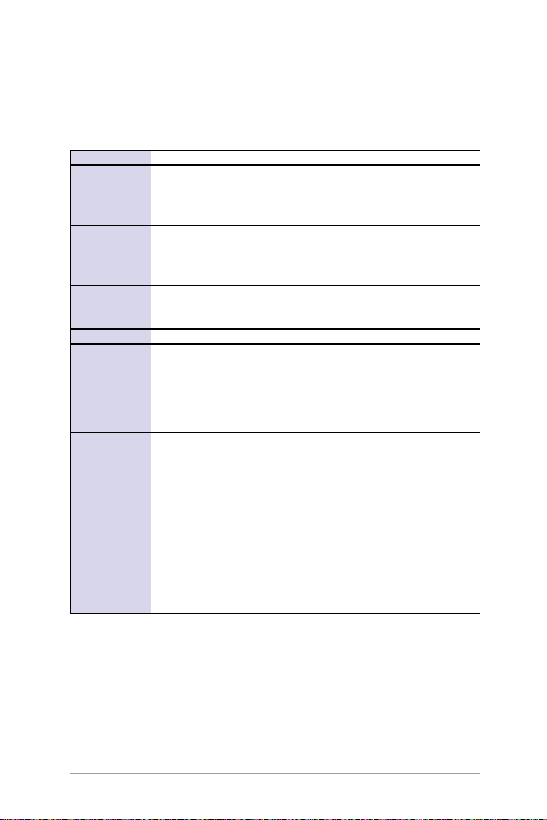
1.3 Front panel features
The barebone server displays a simple yet stylish front panel with easily
accessible features. The power and reset buttons, LED indicators, location
switch, optical drive, and two USB ports are located on the front panel.
Refer to section 1.6.1 Front panel LEDs for the LED descriptions.
Rack screw
Optical drive
Hot-swap HDD bay 1-4
HDD LED
Rack screw
USB ports
System button and LED
HDD Access, LAN, Message LED
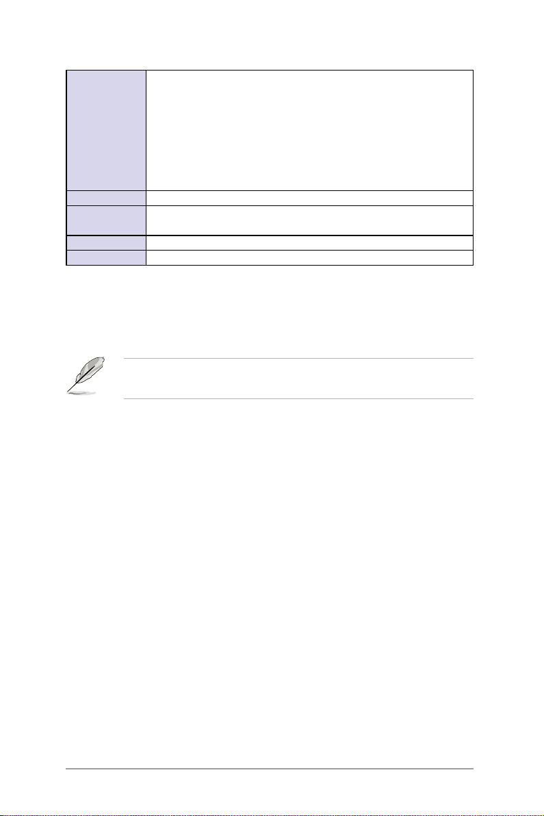
1.4 Rear panel features
The rear panel includes the expansion slot, system power socket, and rear
fans. The middle part includes the I/O shield with openings for the rear
panel connectors on the motherboard.
11
10
7
6
8
9
5
1. Redundant AC power socket
2. Rear fans
3. PS/2 mouse port
4. PS/2 keyboard port
5. USB ports
6. Serial port (for user install self)
7. VGA port
3
4
8. LAN port1
9. LAN port2
10. 2 x Expansion slots
11. LAN port3(Only supports ASUS
IMPI2.0 LAN management card)
12.Second redundant AC power
socket (Optional)
1
2
12
The ports for the PS/2 keyboard, PS/2 mouse, USB, VGA, and Gigabit
LAN do not appear on the rear panel if motherboard is not present.
Refer to section 1.6.2 Rear panel LEDs for the LED descriptions.
ASUS RS162-E4/RX4
1-5
Page 16
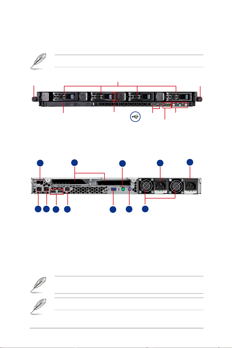
1.5 Internal features
The barebone server includes the basic components as shown.
2
4
9
2
1
4
5
8
10
3
11
7
6
12
13
1. PCI-X riser card bracket
2. Power supply rear fans
3. ASUS DSBF-DR12 motherboard
4. Redundant power supply
5. Device fans (40mm x 56mm) x 2
6. System fans (40mm x 28mm) x 5
7. PCI-X and PCI-E riser card
1-6
8. SAS/SATA-II backplane
9. Hot-swap HDD tray 1(port0)
10. Hot-swap HDD tray 2(Port1)
11. Hot-swap HDD tray 2(Port2)
12. Hot-swap HDD tray 2(Port3)
13. Slim optical drive
Chapter 1: Product Introduciton
Page 17
1.6 LED information
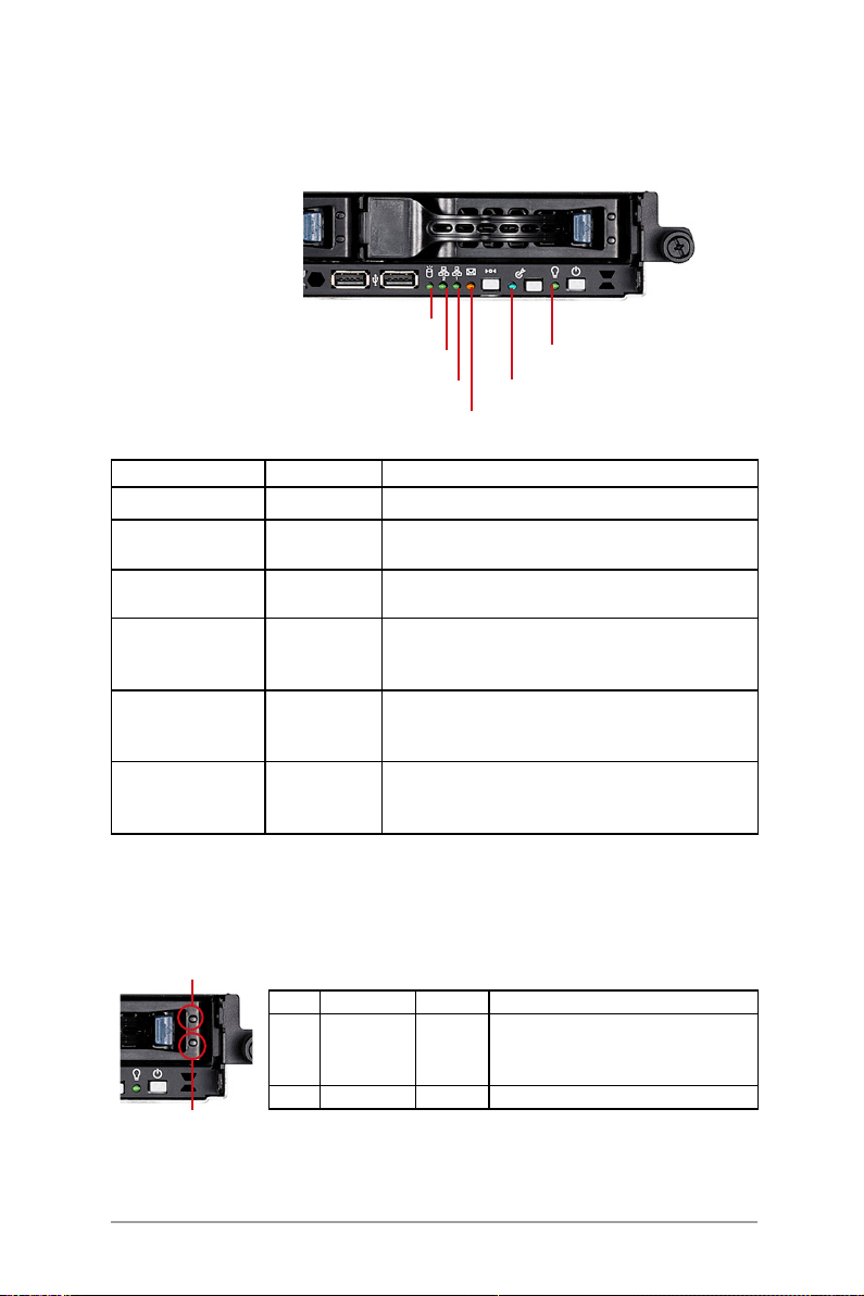
1.6.1 Front panel LEDs
HDD Access LED
LAN2 LED
LAN1 LED
LED Display status Description
Power LED ON System power ON
HDD Access LED OFF
Blinking
HDD Status access ON
OFF
Message LED OFF
ON
Location LED
LAN LEDs OFF
OFF
ON
Blinking
ON
No activity
Read/write data into the HDD
HDD is present
No HDD present
System is in normal condition; no incoming event
ASWM detects a system problem;
(Log in to ASWM to identify and resolve)
Normal status
Location switch is pressed
(Press the location switch again to turn off)
No LAN connection
LAN is transmitting or receiving data
LAN connection is present
Location LED
Message LED
Power LED
1.6.2 HDD status LED
HDD status LED 1
SCSI HDD LED status Description
LDE1 GREEN
RED
RED/GREEN
LDE2 GREEN Blinking Read/write data into the SAS HDD
HDD status LED2
ASUS RS162-E4/RX4
ON
ON
Blinking
SAS/SATA-II HDD power ON
SASHDD failure
SAS RAID reset
1-7
Page 18
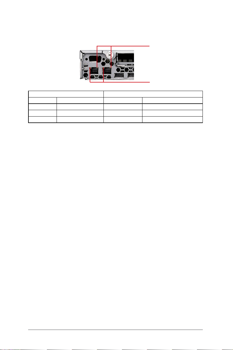
1.6.3 Rear panel LEDs
SPEED LED
ACT/LINK LED
ACT/LINK LED SPEED LED
Status Description Status Description
OFF No link OFF 10Mbps connection
Green Linked Orange 100Mbps connection
Blinking Linking Green 1000Mbps connection
1-8
Chapter 1: Product Introduciton
Page 19

Chapter 2
This chapter lists the hardware setup
procedures that you have to perform
when installing or removing system
components.
Hardware Setup
Page 20
2.1 Chassis cover
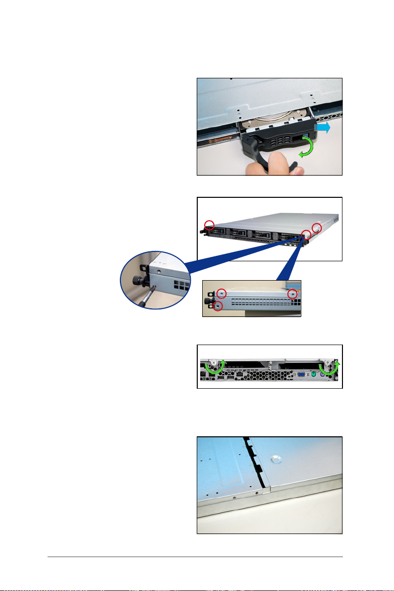
2.1.1 Remove the front cover
1. Push the blue button to the right
side and pull the lever outward
(see the figure) to remove the
hard disk tary.
2. Remove the six screws (refer to
the figure for the locations) on
the left and right sides of the
front side of the top cover panel.
3. Loosen t he two s cre ws t hat
scure the top cover panel to the
rear panel (refer to the gure for
the locations). Please note that
do not remove the screws when
loosenning them.
4. P u s h the b a c k co ver p a n e l
ba ckward until it i s hal f inc h
away from the front side of the
top cover panel.
2-2
Chapter 2: Hardware setup
Page 21
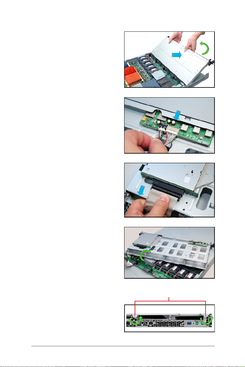
5. Push the front side of the top
cover panel forward and lift it to
expose the cable connectors and
slots underneath.
6. Disconnect the LED cable from
the connec tor on the module
joint to the front panel.
7. Dis connect the opt ica l d rive
cable and power cable.
8. Remove the front upper panel
and set it aside.
2.1.2 Removing the rear cover
1. Loosen the two screws that
fasten the upper panel cover to
the real panel cover. Please note
do not remove the screws when
loosening them.
ASUS RS162-E4/RX4
screws
2-3
Page 22
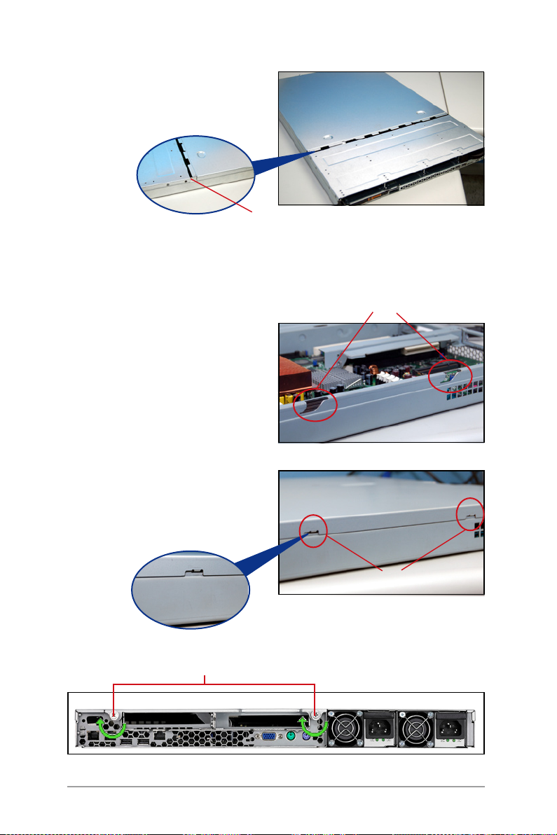
2. Push the back side of the top
cover panel backward until it is
half inch away from the front
upper cover panel.
1/2 inch distance
3. Remove the back top cover panel.
2.1.3 Install the rear cover
1. Locat e the g rooves (se e the
gure). Push the top cover panel
toward the front panel.
2. Match the clips of the top cover
panel with the grooves (see the
figure), and then clinch. Leave
a half inc h distenc e between
the front edge of the top cover
panel and the real panel.
Match the upper cover panel to the
grooves on the left and right sides.
rmly clinched
3. Fasten the two screws as shown below.
screws
2-4
match the clips and the grooves
Chapter 2: Hardware setup
Page 23
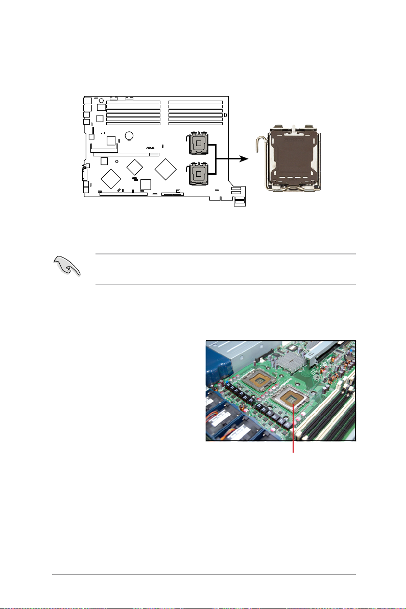
2.2 Install the CPU and heatsink
®
DSBF-DR12
DSBF-DR12 CPU Socket 771
CPU1
CPU2
ASUS RS162-E4/RX4 sever system is powerd by the DSBF-DR12 sever
board, which comes with two ZIF type LGA771 CPU sockets. Intel Xeon
LGA771 CPU has a Dual-Core architecture with 2M L2 cache.
You can install one or two CPUs in this board. When installing only one
CPU, please install it in socket 1.
2.2.1 Installing a CPU
To install a CPU:
1. Locate the CPU socket on the
motherboard.
ASUS RS162-E4/RX4
CPU1 socket
2-5
Page 24
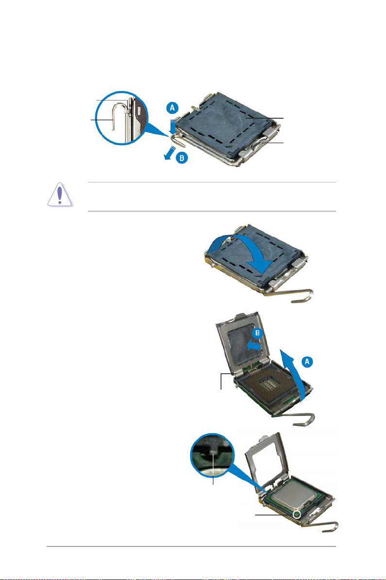
2. Press the load lever with your thumb (A), then move it to the left (B)
until it is released from the retention tab.
Retention tab
Load lever
To prevent damage to the socket pins, do not remove the PnP cap
unless you are installing a CPU.
3. L i f e the lo a d lev e r in the
direction of the arrow.
4. Lift the load p late with you
thumb and forefinger (A), then
push the PnP cap from the load
plate window to remove (B).
5. Position the CPU over the socket,
making sure that the gold triangle
is on the bottom-left corner of
the socket. The socket alignment
key should t into the CPU notch.
PnP cap
Thi s s id e o f the
socket box should
face yuo
load plate
2-6
Alignment key
Gold triangle mark
Chapter 2: Hardware setup
Page 25
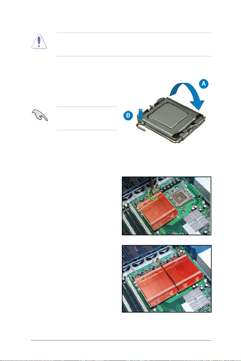
The CPU fits in only one correct orientation. DO NOT force the CPU
into the socket to prevent bending the connectors on the socket and
damaging the CPU!
6. Close the load plate (A), then
push the load lever (B) until it
snaps into the retention tab.
If y o u wa n t to i n s t a l l a
second CPU, follow the steps
above.
2.2.2 Install the CPU heatsink
To install the CPU heatsink:
1. Put the heatsink on the installed
CPU, match the screws with the
screw holes on the board.
2. Fasten two screws at a time in a
diagonal sequence, and then the
other two.
3. Repeat step 1-2 to install the
second CPU heatsink.
ASUS RS162-E4/RX4
2-7
Page 26
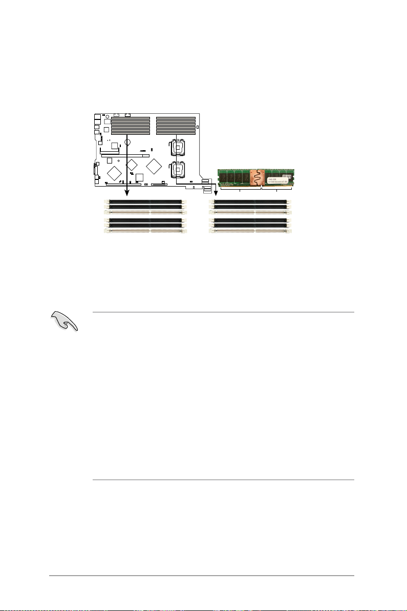
2.3 System memory
®
DSBF-DR12
DSBF-DR12
240-pin FB-DIMM sockets
DIMM_11
DIMM_10
DIMM_12
DIMM_01
DIMM_00
DIMM_02
DIMM_31
DIMM_30
DIMM_32
DIMM_21
DIMM_20
DIMM_22
112 Pins128 Pins
2.3.1 Overview
This sever board comes with twelve Double Data Tate 2 (DDR2) Dual Inline
Memory Modules (DIMM) sockets, support 240-pin Ecc Registered FBD
memory modules.
2.3.2 Memory congurations
You may install 512MB, 1GB, 2GB and 4GB fully buffered Ecc registered
533/667 DDR2 DIMMs into the DIMM sockets.
1. Please install DIMMs with the same CAS latency. We recommend that
you using DIMMs from the same company.
2. Please do not install SS and DS DIMMs together, otherwise the
system might not boot properly.
3. We recommend that you install even number of DIMMs. If you install
only one or singular number of DIMMs, or double FBD DIMMs, please
install it on the white sockets (such as DIMM_00/DIMM_10).
4. Due to chipset resource allocation and the numbers of PCI devices
installed, the system may detected less than 24GB system memory
when you installed twelve 2GB DDR2 memory modules.
5. Whe n y ou inst all thr ee mem ory mod ule s, the syst em is in
unsymmetric dual-channel mode, and the system performance is
in between the performances of single-channel and dual-channel
modes.
2-8
Chapter 2: Hardware setup
Page 27
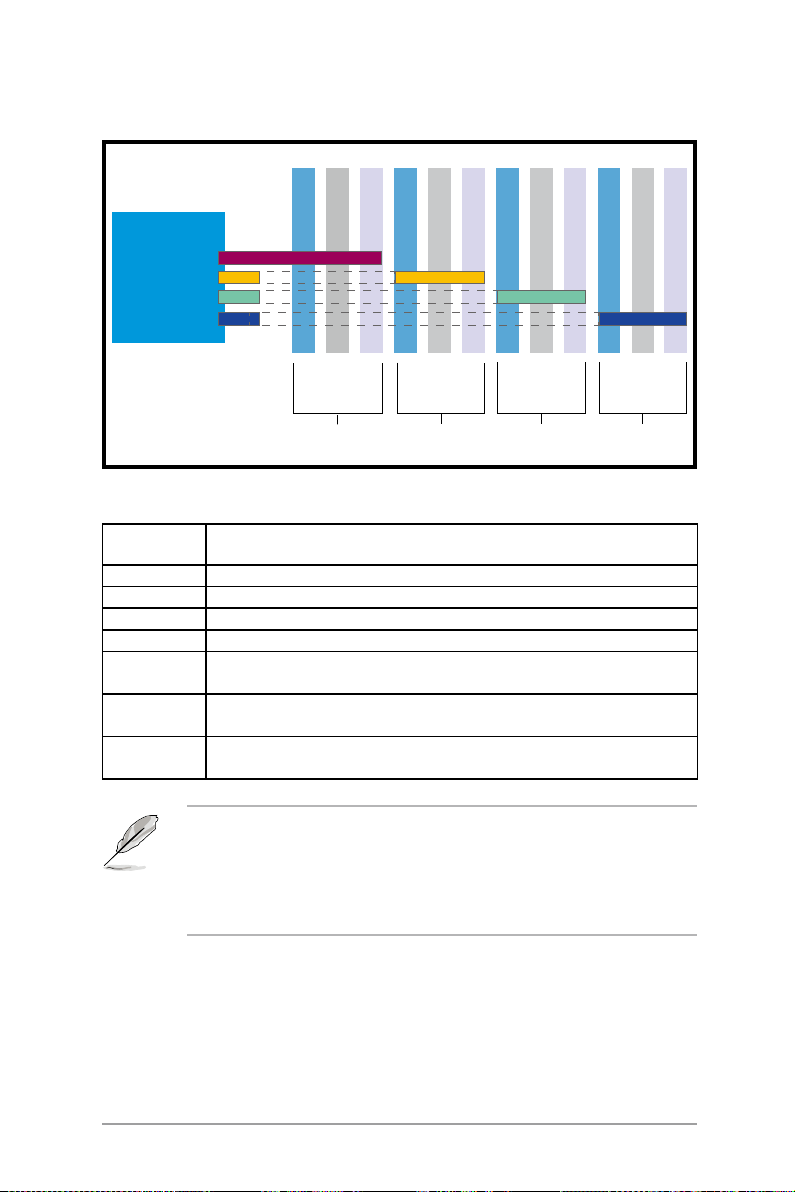
Rank population
MCH
DIMM 01
DIMM 00
DIMM 02
DIMM 10
DIMM 11
DIMM 12
DIMM 20
DIMM 21
DIMM 31
DIMM 22
DIMM 30
DIMM 31
DIMM 32
Channel
Slot 0
Slot 1
Ch:0
Slot 2
Slot 0
Slot 1
Ch:1
Slot 2
Slot 0
Ch:2
Slot 1
Slot 2
Slot 0
Slot 1
Ch:3
DIMM installation reference table
Numbe r s of
DIMM
1 DIMM_00
2 DIMM_00,DIMM_10
4 DIMM_00,DIMM_10,DIMM_20,DIMM_30
6 DIMM_00,DIMM_10,DIMM_20,DIMM_30,DIMM_01,DIMM_11
8 DIMM_00,DIMM_10,DIMM_20,DIMM_30,DIMM_01,DIMM_11,
10 DIMM_00,DIMM_10,DIMM_20,DIMM_30,DIMM_01,DIMM_11,
12 DIMM_00,DIMM_10,DIMM_20,DIMM_30,DIMM_01,DIMM_11,
Slots options
DIMM_21,DIMM_31
DIMM_21,DIMM_31,DIMM_02,DIMM_12
DIMM_21,DIMM_31,DIMM_02,DIMM_12,DIMM_22,DIMM_32
• DIMMs in pair means two DIMMs with the same conguration.
• For better perf ormance, same confi guratio n DIMMs should be
installed on the same slot number for each channel. For example,
you may install the same type of DIMMs in DIMM_00, DIMM_10,
DIMM_20, and DIMM_30.
Slot 2
ASUS RS162-E4/RX4
2-9
Page 28
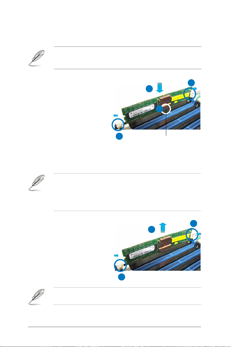
2.3.3 Installing a DIMM
To install a DIMM:
Unplug the power supply before adding or removing DIMMs or other
system components. Failure to do so can cause severe damage to both
the motherboard and the components.
1. U n l o c k a D I M M so c k e t b y
pres s i ng the re tainin g c lips
outward.
2. Alig n a DIM M on t h e s o cket
suc h t hat th e not c h on t h e
DIMM matches the break on the
socket.
3. Firmly insert the DIMM into the
socket until the retaining clips
snap back in place and the DIMM
is properly seated.
· A DDR2 DIMM is keyed with a notch so that it fits in only one
direction. Do not force a DIMM into a socket to aviod damaging the
DIMM.
· The DDR2 DIMM sockets do not support DDR DIMMs. DO not install
DDR DIMMs to the DDR2 DIMM sockets.
2.3.4 Removing a DIMM
1. S i m u l t a n e o u s l y p r e s s t g e
retaining clips outward to unlock
the DIMM.
2. R emove the D I M M f r o m t h e
socket.
1
3
2
1
DDR2 DIMM notch
1
2
2-10
1
Support the DIMM lightly with your ngers when pressing the retaining
clips. The DIMM might get damaged when it ips out with extra force.
Chapter 2: Hardware setup
Page 29
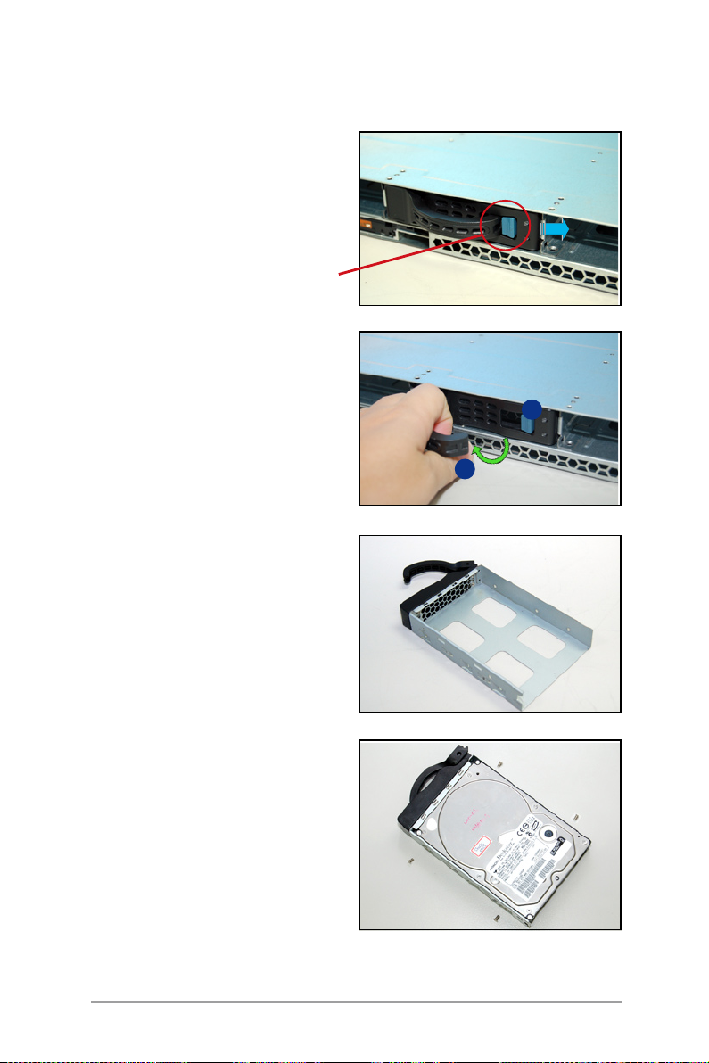
2.4 Hot-swap hard disk drives
To install a hot-swap HDD:
1. Release a drive tray by pushing
the spring lock to the right, then
pulling the tray lever outward.
Th e drive tray eject s slightly
after you pull out the lever.
retaining button
2. Firmly hold the tray lever and pull
the drive tray out of the bay.
3. Take note of the dr ive tray
holes. Each side has three holes
to fit diffe rent types of hard
disk drives. Use two screws on
each side to secure the hard disk
drive.
1
2
4. Place a hard disk drive on the
tray, then secure it four screws.
ASUS RS162-E4/RX4
2-11
Page 30
5. Cearfully insert the drive tray
and push it all the way to the
de pth of the bay un til jus t a
small fraction of the tray edge
prottrudes.
When installed, the SAS/SATA connector on the drive connects to the
SAS/SATA connector on the backplane. Refer to the section 2.7 SAS/
SATA backplane cabling for more information.
6. Push the tary level until clicks,
and secures the d rive tray i n
place. The drive tray is correctly
placed when its front edge aligns
with the bay edge.
7. Refer step 1 to 6 if you wish to
install a second , third and/or
fourth drive.
2-12
Chapter 2: Hardware setup
Page 31

2.5 Expansion slots
2.5.1 Installing expenstion card
ASUS RS162-E4/RX4 sever has a specially designed PCI riser card. If you
want to install PCI-X and PCI Express x8 expension cards, you have to
remove the mental brackets on the real panel of the chassis rst.
To install the PCI-X card: (the slot support PCI-X or 3.3V campatiable PCI
cards.)
1. You can install one PCI Express
x8 c ard a nd one PCI- X car d.
Please carefully hold the PCI-X
riser card and pull it off from the
PCI-X slot on the board.
2. Set the riser card aside. Using a
cross screw driver to remove the
screws as shown.
3. Insert a PCI-X card into the slot
of the riser card, then put the
screws back and fasten it.
ASUS RS162-E4/RX4
2-13
Page 32

To install a PCI Express x8 card: (the slot supports PCI-E x8, x4 and x1
cards)
1. Follow the steps 1-2 on the last
page to remove the riser card. Using
a cross screw driver to remove the
screws on the bracket.
2.Insert the PCI Express card into
the slot, and then secure it with the
screws.
PCI Express x8
2.5.2 Reinstall the riser card
To reinstall the transfer card:
1. Take note of the holes on the
riser card bay. The two pegs on
the riser card bracket should
match these holes ensure that
the bracket is properly in place.
2. Insert the PCI riser card with the installed expansion cards into the PCI
riser card slot on the board. Make sure the golden ngers are completely
inserted into the slots and the mental barcket is properly matched with
the rear panel.
2-14
Chapter 2: Hardware setup
Page 33

2.5.3 Remove the expansion cards
To change expension cards:
1. Pull the riser card upward (see
the arrow in the gure) as shown
to release it from the slot.
2. Set the riser card aside, and then
using a screw driver to remove
the screws on the card.
3. Remove the expension card from
the riser card.
2.5.4 Installing the SAS expansion slot
This product package provide a SAS expansion module for you to purchse
optionally. If you want to install any peripherial SAS devices, please follow
the steps below:
1. Remove the riser card from the
system.
This opti ona l mod ule w ill
use the slot on the PCI riser
card, please cosider the total
number of expansion cards
yo u pla n to insta ll in th e
system.
ASUS RS162-E4/RX4
2-15
Page 34

2. P r e p are t h e S A S e x p a n s i o n
module. connect it to the riser
card and secure it.
3. Put back the riser card to its slot
on the board.
4. Connect the cable.
2.5.5 Install ZCR card (Optional)
The system package provide an optional ZCR card. If you want to install it,
follow the steps below:
1. The Z C R card co mes wi th a
battery module card(optional),
before you install the ZCR card,
remove the battery module card
and install a battery rst.
2-16
Chapter 2: Hardware setup
Page 35

2. Using a screw driver to secure
the three scews on the battery
moduel cards.
If there is no battery module card on your ZCR card, please skip step 1-2
and start from step 3.
3. Using a screw driver to remove
the two screws that secures the
bracket of the ZCR card.
4. Insert the ZCR card into the slot
on the transfer card.
5. Put the two retaining poles into
the holes on the system board.
The two retaining poles are
provided along with the ZCR
card package.
ASUS RS162-E4/RX4
2-17
Page 36

6. Inser t the tr ansfe r card with
the installed ZCR card into the
transfer card slot on the system
board.
7. Using two screws to secure the
card with the retainng poles on
the system board.
2.5.6 Conguring an expansion card
After installing the expansion card, congure it by adjusting the software
settings.
1. Turn on the system and change the necessary BIOS settings, if any. See
Chapter 5 for information on BIOS set up.
2. Assign an IRQ to the card. Refer to the following tables.
3. Install the software drivers for the expansion card.
2-18
Chapter 2: Hardware setup
Page 37

Standard interrupt assignments
IRQ Priority Standard Function
0 1 System Timer
1 2 Kayboard Controller
2 N/A Progerammable Interrupt
3* 11 Communications Port (COM2) *
4* 12 Communications Port (COM1) *
5* 13 Sound Card (cometimes LPT2)
6 14 Floppy Disk Controller
7*
15 Printer Port (PT1)
8 3 System CMOS/Real time clock
9* 4 ACPI Mode when used
10* 5 IRQ Holder for PCI Steering
11* 6 IRQ Holder for PCI Steering
12* 7 PS/2 Compatible Mouse Port
13 8 Numeric Data Processor
14* 9 Primary IDE Channel
15* 10 Secondary IDE Channel
*These IRQs are usually available for expansion cards.
IRQ assignments for this motherboard
PATA controller PIRQA#
INTA# INTB# INTC# INTD# REQ# GNT#
SATA controller PIRQD#
SMBus controller PIRQB#
USB UHCI controller 1 PIRQA
USB UHCI controller 2 PIRQD
USB 2.0 UHCI controller PIRQH
82563EBX1 PIRQB
82563EBX2 PIRQB
ATI Rage XL PIRQB REQ1# GNT1#
PCIX Slot1 (64-bit) PXIRQ0 PXIRQ1 PXIRQ2 PXIRQ3 PXREQ0 PXGNT0
PCI Express Slot 2 PIRQA#
PCIX Slot 2 (64-bit) PXH_IRQ#0 PXH_IRQ#1 PXH_IRQ#2 PXH_IRQ#3 REQ0# GNT0#
When using PCI cards on shared slots, ensure that the drivers support
"Share IRQ" or that the cards do not need IRQ assignments. Otherwise,
conflicts will arise between the two PCI froups, making the ystem
unstable and the card inoperable.
ASUS RS162-E4/RX4
2-19
Page 38

2.6 Cable connections
1
7
2
6
3
5
4
Pre-connected system cables
1. PSU connectting card (connects PSU and the board)
2. Rear pa ne l SA S/SATA2 power connector (hide under the panel,
connects to PSU
3. IDE cable port (hide under chassis, connect rear panel SAS/SATA2 to
optical drive
4. System Fan connector (connect rear panel SAS/SATA2 to system fan)
5. Bridge cards (three), (hide under the cover panel, connect the system
board to rear panel SAS/SATA2)
6. Device fan connector (rear panel SAS/SATA2 to device fan)
7. COM1 cable port (system board to COM1 openning)
2-20
Chapter 2: Hardware setup
Page 39

2.6.1 Serial Port cable
The system package provides a set of COM port cable module. You can
install it into the COM1 openning on the rear panel. To install it:
1. Prepare the COM1 port ca ble
m o d u l e f r o m y o u r pr o d u c t
package.
2. O p e n the t o p co v e r p a n e l .
Connect one end of the cable
to the COM1 connector on the
board, and then t the other end
into the COM1 openning of the
rear panel.
3. Secure the rear panel COM1 port
to the rear panel using the two
screws (see the gure).
4. Re-place the top cover panel.
ASUS RS162-E4/RX4
2-21
Page 40

2.7SAS/SATAbackplanecabling
2-22
Connects 8-pin
power plug
CON2_FAN
CON1_FAN
Connect CPU/system fan cables
CON4_FAN56
CON3_FAN34
3 PCI bridge
cards
Port0 Port1
Connects SAS/SATA2 hard disk drive
CON6_FAN910
CON5_FAN78
Port2
The system fans run in full speed during POST.
Chapter 2: Hardware setup
CON7_FAN1112
Port3
Page 41

2.8 Remove components
Before install/uninstall devices,you might need to remove the pre-installed
components in the system. This section tells you how to remove/install the
components.
1. System fans
2. Device fans
3. Redundant PSU and power backplane board
4. SAS/SATA2 Backplane and bridge cards
5. Optical drive
6. Motherboard
2.8.1 System fans
The system provides the follow fan sets:
· Five 40mm x 56mm 15500rpm fans (Dual-fans for unit)
· Two 40mm x 28mm 15500rpm fans
Refer to the gure below for the location of the fans.
40mm x 56mm system fans
40mm x 28mm devices fan assembly
Improper installation of the fan assembly might cause CPU overheat or
system shut down.
ASUS RS162-E4/RX4
2-23
Page 42

To remove the system fans:
1. Disconnect the fan cable from
t h e fan co n n e c t o r on th e
backplane board.
2. Lift the fan, then set aside.
3. Rep eat steps 1-2 to remove
other fans.
To install the system fans:
1. I n s e r t th e fan t o t h e fa n
cage. Take note of the airflow
embossed on the fan side
2. Connect the system fan cable
to the fan c onnector on the
backplane board.
2-24
Chapter 2: Hardware setup
Page 43

2.8.2 Device fans
The system comes with two 40mm x 28mm device fans (15500 rpm),
please refer to the gure below for the location.
40mm x 28mm device fan assembly
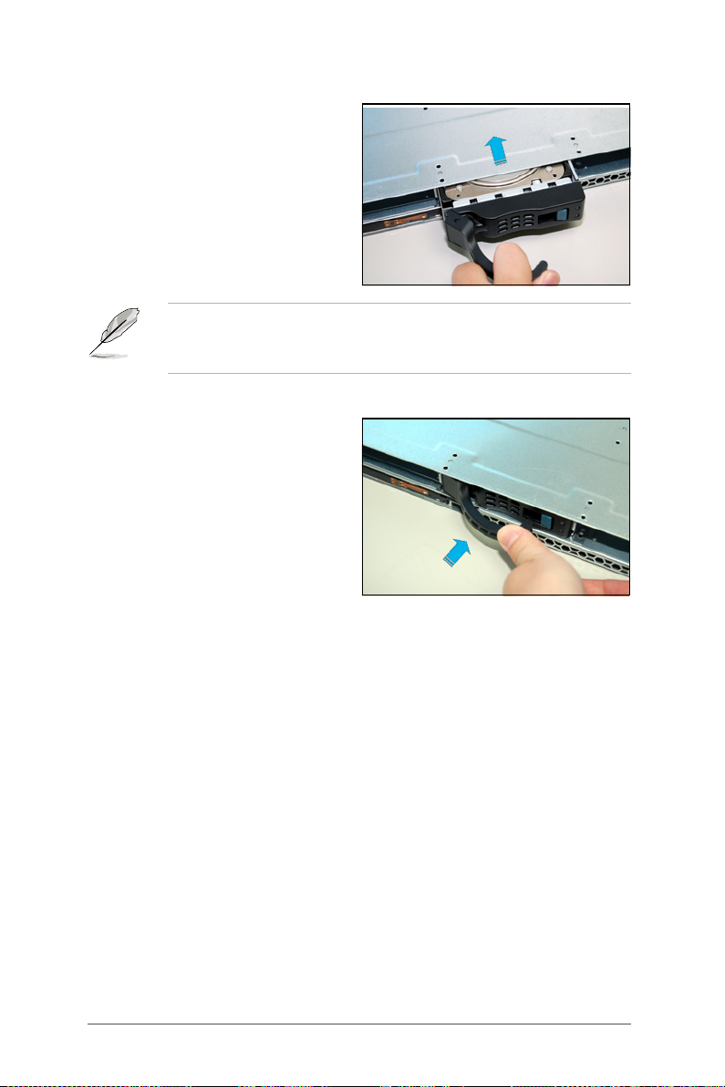
To remove the device fans:
1. Disconnect the device fan cable
form t h e c o n n e c t o r o n th e
backplane board.
2. Lift the fan, then set aside.
To install the device fan:
1. I n s e r t t h e fa n to th e fa n
cage. Take note of the airflow
directional arrows embossed on
the fan side.
2. Connect the device fan cable
to the fan connector o n t he
backplane board.
2.8.3 Device fan with dummy case
The device fan for the PSU comes with a dummy case that allows it to t in
the fan cage. Follow these instructions when replacing these fans.
1. Follow the instruction above to
remove the fan from the system.
2. Using a screw driver to remove
the t w o s c r e w s on the fan
assembly as shown.
ASUS RS162-E4/RX4
2-25
Page 44
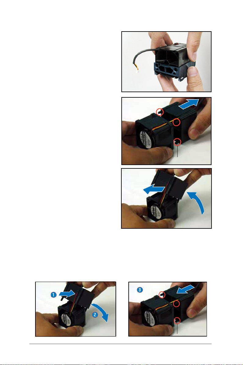
3. Remove the fan from the fan
assembly as shown.
4. Uninstall the fan following the
ins t ructi ons i n the pervi o us
section.
5. Pull the d ummy case to the
d i r e c t i o n of the ar r o w t o
disengage i ts p egs from the
device fan.
6. Move the half of the cover box
upward, then remove the cables
(as arrow show).
7. Replace the device fan.
Retaining tab
To change the fan and reinstall the dummy case:
1. Put the fan power cables into the cable groove on dummy case as
shown.
2. Move the half part of the dummy case to the back of the fan as shown.
3. Match the retaining tab with its notch and lock it.
4. Put the device fan with the dummy case into the fan cage.
Retaining tab
2-26
Chapter 2: Hardware setup
Page 45

2.8.4 Redundant PSU and Power backplabe board
The system comes with a PSU that can be easily removed/installed. To
remove the PSU and the Power backplane board:
To remove the redundant PSU:
1. Press the retaining tab on the
PSU as shown.
2. Pull the PSU outward and remove
it.
3. F o l l o w s t e p 1 - 2 to re m o v e
another PSU.
Remove the Power backplane board
1. After remove the PSU, remove
the device fan as shown.
2. Using a screw driver to remove
the two screws on the power
cable cover.
ASUS RS162-E4/RX4
2-27
Page 46

3. Remove the 8-pin power cable
conne cte d to t he SAS /SA TA
backplane board.
4. Push the power backplane board
as shown until it is completely
removed from the motherboard.
5. Set the power backplane board
aside.
6. Using a screw driver to remove
the screw on the back of the
po wer backpla ne board, then
remove the PSU power backplane
board.
2-28
Chapter 2: Hardware setup
Page 47

Install the PSU and Power backplane
1. Match the screw with the screw
hole and use a screw driver to
fasten it as shown to secure the
power backplane board with the
cover.
2. Put the power backplane board
into its place as shown.
3. P u s h th e po w e r back p l a n e
board forward as shown until a
sligt sound indicates the board
is f i r m l y c o n n e c ted t o the
motherboard.
4. Connect the 8-pin power cable
to the rear panel SAS/SATA2
backplane board.
ASUS RS162-E4/RX4
2-29
Page 48

5. Using a screw driver to fasten
the two screws on the power
cable cover.
6. P u t t h e d e v i c e f a n i n t o i t s
groove and connect the power
cable.
7. Push the PSU into the chassis
until a slight sound indicates it is
properly seated in its place.
2-30
Chapter 2: Hardware setup
Page 49

2.8.5 SAS/SATA2 Backpanel and Bridge Card
Follow the steps below to remove/install SAS/SATA2 Backplane and the
Bridge Card.
To remove the bridge card and and SAS/SATA Backplane:
1. Remove the top cover panel,
then disconnect the 8-pin power
co rd to the SAS /SATA 2 rear
panel.
2. Disconnect the fan cables to the
rear panel.
3. Using a screw driver to remove
the screws on the cover of the
bridge card.
4. R emove t h e c o v er panel t o
expose the bri dge card that
connects SAS/SATA2 rear panel
and the system board.
ASUS RS162-E4/RX4
2-31
Page 50

5. Hold the bridge card and pull out
it.
6. Loosen the screws on the SAS/
SATA2 Backplane.
7. Push the SAS/SATA2 Backplane
as shown and remove it.
8. Remove the IDE cable and FPB/
USB cable.
Install Bridge card and SAS/SATA2 Backplane
1. Connect the IDE and FPB/USB
cable.
2-32
Chapter 2: Hardware setup
Page 51

2. Push the SAS/SATA2 Backplane
as shown until it is rmly seated.
3. Fasten the screws.
4. Insert the bridge cards.
5. Reinstall the Bridge cards cover,
use cross screw driver to fasten
it.
6. Connect all the fan cables and
8-pin power cable.
ASUS RS162-E4/RX4
2-33
Page 52

2.8.6 Optical drive
The system come with a DVD drive (CD-ROM/DVD-ROM), follow the steps
below if you want to change it:
1. Push the blue button to the right
side and pull the lever outward
(see the figure) to remove the
hard disk tray.
2. Remove the six screws (refer to
the figure for the locations) on
the left and right sides of the
front side of the top cover panel.
3. Loosen t he two s cre ws t hat
scure the top cover panel to the
rear panel (refer to the gure for
the locations). Please note that
do not remove the screws when
loosenning them.
4. P u s h th e back c o v e r pa n e l
ba ckwar d unt il it is half inch
away from the front side of the
top cover panel.
2-34
Chapter 2: Hardware setup
Page 53

5. Lift the front side of the top
cover panel to expose the cables
connectors underneath.
6. Disconnect the LED cables to the
front panel.
7. Disconnect the cable and power
cable of the optical drive.
8. Remove the front side of the top
cover panel and set it aside.
9. Use a Phillips screwdriver (cross)
t o rem o v e the sc r e w t h a t
secures the drive.
ASUS RS162-E4/RX4
2-35
Page 54

10. Using a screw driver to remove
t h e sc r e w s as sh o w n , and
remove the riser card.
11. Pull the optical drive carefully
and remove it as shown.
Th e ID E interface of thi s
system is specially designed,
pl ease do not use o pt ical
d r i v e o f other br a n d s .
Otherwise the optical drive
might be damaged due to
capatibility problem.
Follow the steps below to reinstall
the optical drive:
1. Place the optical drive in its place
as shown.
2. Using a screw driver fasten the
screws to secure the riser card
to the optical drive.
3. Secure the three screws that
secure th e op t i cal drive a s
shown.
4. Connect the cables and put back
the front side of the front cover.
2-36
Chapter 2: Hardware setup
Page 55

2.8.7 Motherboard
®
DSBF-DR12
®
DSBF-DR12
Remove the motherboard
To remove the motherboard:
1. Remove all the siginal cables and power cables connected to the system
board. Please refer to section 2.6 for more information about cables.
2. Remove all the devices including CPU, heatsink,PCI transer card and FBD
memory modules that connect
to the b oar d. Ple ase re fer to
the relevant sections for more
information.
3. Remove the PCI riser card and the
screws on it.
4. Remove the PSU Power backplane
and the bridge card. Remove all
the components connected to
the board as shown.
5. Remove the thirteen screws that
secure the board to the chassis.
6. Remov e the bo ards fro m the
chassis carefully as shown.
Th e ret ain ing p ol e is for
securing the ZCR card.
ASUS RS162-E4/RX4
Retaining poles
securing holes
2-37
Page 56

Install the system board
To install the motherboard:
1. Hold t he b oard by e dges a s
shown and carefully place it in
the chassis.
2. Carefully move the board into its
place until it is properly seated.
3. Match all t he sc rew hole and
secure the board to the chassis
using the thirteen screws.
4. Follow the steps in previous sections to install the PSU Power backplane,
Bridge card and cables. Refer to section 2.6 for the instruction of
connecting cables.
5. Reinstall the CPU and heatsink, PCI riser card and FBD memory modules.
2-38
Chapter 2: Hardware setup
Page 57

ASUS RS162-E4/RX4
2-39
Page 58

2-40
Chapter 2: Hardware setup
Page 59

ASUS RS162-E4/RX4
2-41
Page 60

2-42
Chapter 2: Hardware setup
Page 61

Chapter 3
This chapter describes how to install
the optional components and devices
into the barebone server.
Installation options
Page 62

3.1 Rackmount rail kit items
If you have the rackmount rail kit, it contains two pairs of rails (one pair for
each side of the barebone system), and eight (8) pairs of nut-and-bolt type
screws.
Nuts
Bolts
Left pair
Right pair
3.2 Rack rails assembly
To assemble the rack rails:
1. Determine the depth of the rack where you wish to install the system.
2. Match one long and one short rail to your desired length, and x them
together using four (4) pairs of nuts and bolts.
3. Repeat step 2 to assemble the other rail pair.
3-2
Rear ends
Bolts on inner side
Nuts on outer side
Front ends
Chapter 3: Installation options
Page 63

3.3Attachingtherailstotherack
To attach the rails to the rack:
1. Select one unit of space (1U)
on the rack where you wish to
install the barebone server.
2. Remove the screws from the 1U
space on the rack front.
3. Align the front end holes of a
rack rail pair to the 1U space.
4. Drive in two screws on the outer
holes to secure the front end.
1U space
5. Find the rear 1U space that corresponds to the front 1U space where
you attached the rail.
6. Remove the screws from the rear 1U space, and align the rear end
holes.
7. Drive in two screws on the outer holes to secure the rear end.
8. From the rack front, nd the corresponding 1U space for the second rail
pair.
9. Repeat steps 2 to 7 to attach the second rail pair. When properly
installed, the rack rails appear as shown.
ASUS RS162-E4/RX4
3-3
Page 64

3.4Rackmountingtheserver
To mount the server to the rack:
1. Firmly hold the server on both sides and insert the rear panel side to
the front end of the rack rail, then carefully push the server all the way
to the back until the front panel ts the front end of the rack, and the
rack screws on the server match the middle hole on the rack.
2. Tighten the two rack screws to
secure the server to the rack.
3-4
Rack screw
Chapter 3: Installation options
Page 65

Chapter 4
This chapter includes the motherboard
layout, and brief descriptions of the
jumpers and internal connectors.
Motherboard info
Page 66

AMI
8Mb
FWH
KBPWR1
®
ATI
ES1000
Supe r
I/O
CR2032 3V
Lithium Cell
CMOS Power
CPLD1
HDLED1
RAID_SEL1
USBPW1
CLRTC1
VGA_EN1
RECPVERY1
LAN1_EN1
SB_PWR1
SAS_EN1
USBPW2
DSBF-DR12
BP_CON2
DDR DIMM00 (64/72 bit, 240-pin module)
COM2
SAS_CON1
VGA1
MS1KB1
LED1
LOCSW1
LAN1
USB2USB1
DDR DIMM01 (64/72 bit, 240-pin module)
DDR DIMM02 (64/72 bit, 240-pin module)
DDR DIMM10 (64/72 bit, 240-pin module)
DDR DIMM11 (64/72 bit, 240-pin module)
DDR DIMM12 (64/72 bit, 240-pin module)
DDR DIMM20 (64/72 bit, 240-pin module)
DDR DIMM21 (64/72 bit, 240-pin module)
DDR DIMM22 (64/72 bit, 240-pin module)
DDR DIMM30 (64/72 bit, 240-pin module)
DDR DIMM31 (64/72 bit, 240-pin module)
DDR DIMM32 (64/72 bit, 240-pin module)
PCIE1 PCIE2
PCIX2
LAN2
COM1
BP_CON3
BP_CON4
BP_CON1
CPU1
CPU2
CPU_FAN2
BUZZER1
TPM1
BMCSOCKET1
CPU_FAN1
4.1 Motherboard layout
4-2
Chapter 4: Motherboard information
Page 67

Layout contents
Slots/Sockets Page
1. CPU sockets
2. DDR2 DIMM sockets
3. PCI/PCI-X slots
4. Zero-Channel RAID socket
5. Mini-PCI socket
Jumpers Page
1. Clear RTC RAM (3-pin CLRTC1)
2. USB device wake-up (3-pin USBPW12, USBPW34)
3. Keyboard power (3-pin KBPWR1)
4. VGA controller setting (3-pin VGA_EN1)
5. Gigabit LAN1 controller setting (3-pin LAN1_EN1)
6. SAS setting (3-pin SAS_EN1)
7. Force BIOS recovery setting (3-pin RECOVERY1)
Internal connectors Page
1. Hard disk activity LED connector (4-pin HDLED1)
2. Serial port connector (10-1 pin COM2)
4-2
4-2
4-2
4-2
4-2
4-4
4-5
4-5
4-6
4-6
4-7
4-8
4-8
4-13
ASUS RS160-E4/RX4
4-3
Page 68

4.2 Jumpers
®
DSBF-DR12
DSBF-DR12 Clear RTC RAM
CLRTC1
Normal
(Default)
Clear CMOS
1
2
2
3
1.ClearRTCRAM(CLRTC1)
This jumper allows you to clear the Real Time Clock (RTC) RAM in
CMOS. You can clear the CMOS memory of date, time, and system setup
parameters by erasing the CMOS RTC RAM data. The onboard button
cell battery powers the RAM data in CMOS, which include system setup
information such as system passwords.
To erase the RTC RAM:
1. Turn OFF the computer and unplug the power cord.
2. Remove the onboard battery.
3. Move the jumper cap from pins 1-2 (default) to pins 2-3. Keep the cap
on pins 2-3 for about 5~10 seconds, then move the cap back to pins
1-2.
4. Reinstall the battery.
5. Plug the power cord and turn ON the computer.
6. Hold down the <Del> key during the boot process and enter BIOS setup
to re-enter data.
Except when clearing the RTC RAM, never remove the cap on CLRTC
jumper default position. Removing the cap will cause system boot
failure!
4-4
Chapter 4: Motherboard information
Page 69

2.USBdevicewake-up(3-pinUSBPW12)
®
DSBF-DR12
DSBF-DR12 USB device wake up
USBPW1
(Default)
+5V +5VSB
3221
USBPW2
(Default)
+5V +5VSB
3221
®
DSBF-DR12
DSBF-DR12 Keyboard power setting
KBPWR1
1
2
(Default)
+5V +5VSB
2
3
Set these jumpers to +5V to wake up the computer from S1 sleep mode
(CPU stopped, DRAM refreshed, system running in low power mode) using
the connected USB devices. Set to +5VSB to wake up from S4 sleep mode
(no power to CPU, DRAM in slow refresh, power supply in reduced power
mode).
・ The USB device wake-up feature requires a power supply that can
provide 500mA on the +5VSB lead for each USB port; otherwise,
the system would not power up.
・ If you are using Windows 2000, you need to install Service Pack 4
to wake up the system from S4 sleep mode.
・ The total current consumed must NOT exceed the power supply
capability (+5VSB) whether under normal condition or in sleep
mode.
3.Keyboardpower(3-pinKBPWR1)
This jumper allows you to enable or disable the keyboard wake-up feature.
Set this jumper to pins 2-3 (+5VSB) to wake up the computer when you
press a key on the keyboard (the default is the Space Bar). This feature
requires an ATX power supply that can supply at least 1A on the +5VSB
lead, and a corresponding setting in the BIOS.
ASUS RS160-E4/RX4
4-5
Page 70

®
DSBF-DR12
DSBF-DR12 LAN_EN setting
LAN_EN1
Enable
(Default)
Disable
3
22
1
4.VGAcontrollersetting(3-pinVGA_EN1)
®
DSBF-DR12
DSBF-DR12 VGA setting
VGA_EN1
Enable
(Default)
Disable
3
22
1
These jumpers allow you to enable or disable the onboard ATI RAGE-XL PCI
VGA controller. Set to pins 1-2 to activate the VGA feature.
5.GigabitLAN1controllersetting(3-pinLAN1_EN1)
This jumper allows you to enable or disable the on board Broadcom
BCM5721 Gigabit LAN1 controller. Set to pins 1-2 to activate the Gigabit
LAN feature.
4-6
Chapter 4: Motherboard information
Page 71

6.SAScontrollersetting(3-pinSAS_EN1)
®
DSBF-DR12
DSBF-DR12 SAS setting
SAS_EN1
Enable
(Default)
Disable
12 23
®
DSBF-DR12
DSBF-DR12 BIOS recovery setting
RECOVERY1
3
22
1
(Default)
Normal BIOS Recovery
This jumper allows you to enable or disable the onboard LSI SAS1068
controller. Set to pins 1-2 to activate the SAS feature, and support RAID
congurations.
Important! If set to pin 2-3 to disable the SAS feature, the motherboard
will not detect HDDs.
7.ForceBIOSrecoverysetting(3-pinRECOVERY1)
This jumper allows you to quickly update or recover the BIOS settings when
it becomes corrupted.
To update the BIOS:
1. Prepare a oppy disk that contains the latest BIOS for the motherboard
(xxxx-xxx.ROM) and the AFUDOS.EXE utility.
2. Set the jumper to pins 2-3.
3. Insert the oppy disk then turn on the system to update the BIOS.
4. Shut down the system.
5. Set the jumper back to pins 1-2.
6. Turn on the system.
ASUS RS160-E4/RX4
4-7
Page 72

4.3 Connectors
®
DSBF-DR12
DSBF-DR12 Serial port connectors
COM1
PIN 1
COM2
PIN 1
®
DSBF-DR12
DSBF-DR12 SAS/SATA2 card activity LED connector
HDLED1
1
SCSI_ACTLED-
SCSI_ACTLED+
SCSI_ACTLED+
SCSI_ACTLED-
1.IDEconnectors(40-1pinPRI_IDE,SEC_IDE)
This connector supplies power to the hard disk activity LED.The read or
write activities of any device connected to the SCSI connectors or the
SATA connectors cause this LED to light up.
2.Serialportconnector(10-1pinCOM2)
This connector is for a serial (COM) port. Connect the serial port module
cable to this connector, then install the module to a slot opening at the
back of the system chassis.
4-8
Chapter 4: Motherboard information
Page 73

Chapter 5
Thi s chapt er tel l s how t o chan g e
the system settings through the BIOS
Setup menus. Detailed descriptions
of the BIOS parameters ar e al s o
provided.
BIOS Setup
Page 74

5.1ManagingandupdatingyourBIOS
The following utilities allow you to manage and update the motherboard
Basic Input/Output System (BIOS) setup.
1. Phoenix Phlash16 BIOS Flash Utility (Updates the BIOS in DOS mode
using a bootable oppy disk.)
2. ASUS CrashFree BIOS 2 (Updates the BIOS using a bootable floppy
disk or the motherboard support CD when the BIOS file fails or gets
corrupted.)
3. ASUS Update (Updates the BIOS in Windows
Refer to the corresponding sections for details on these utilities.
Save a copy of the original motherboard BIOS le to a bootable oppy
disk in case you need to restore the BIOS in the future. Copy the original
motherboard BIOS using the ASUS Update or AwardBIOS Flash utilities.
5.1.1 Creating a bootable oppy disk
1. Do either one of the following to create a bootable oppy disk.
DOS environment
a. Insert a 1.44MB oppy disk into the drive.
b. At the DOS prompt, type
Windows® XP environment
a. Insert a 1.44 MB oppy disk to the oppy disk drive.
b. Click Start from the Windows
c. Select the 3 1/2 Floppy Drive icon.
d. Click File from the menu, then select Format. A Format 3 1/2 Floppy
Disk window appears.
e. Select Create an MS-DOS startup disk from the format options field,
then click Start.
format A:/S
®
desktop, then select My Computer.
®
environment.)
then press <Enter>.
2. Copy the original or the latest motherboard BIOS le to the bootable
oppy disk.
3. Delete cong.sys and autoexec.bat from oppy disk.
Phlash16 does not run in any environment with memory management
such as an MS-DOS Window or Window Console. Do not run MS-DOS with
CONFIG.SYS or AUTOEXEC.BAT. Do not open any memory manager such
as HIMEM.SYS or EMM.386. Refer to Appendix for detailed information.
5-2
Chapter 5: BIOS setup
Page 75

5.1.2 Updating the BIOS u s ing the P h o e n ix
Phlash16 Utility
The Basic Input/Output System (BIOS) can be updated using the Phoenix
Phlash16 Utility. Follow these instructions to update the BIOS using this
utility.
1. Download the latest BIOS le from the ASUS web site. Save the le to a
oppy disk.
Make sure you copy the correct BIOS le for the specic model of your
motherboard. Save only the updated BIOS le in the oppy disk to avoid
loading the wrong BIOS le.
2. Copy the Phoenix Phlash16 (phlash16.exe) utility from the Software
folder of the support CD to the oppy disk with the latest BIOS le.
3. Boot the system in DOS mode using the bootable floppy disk you
created earlier.
4. After posting and reading the boot data from floppy, press <F5> to
bypass some unnecessary les.
5. When the A:> appears, replace the bootable oppy disk with the oppy
disk containing the new BIOS le and the Phoenix Phlash16 Utility.
6. At the prompt, type the following command string:
<Format>
Phlash16 /mode=3 [Driver label][File Name]
<Example>
Phlash16 /mode=3 A:\BIOS.WPH
7. The Phoenix Phlash16 Utility automatically updates the BIOS.
Do not turn off or reset the system during the ashing process!
8. Restart the system after the utility completes the updating process.
Make sure you remove the oppy disk from the drive.
When you execute the Phlash16.exe. program and the screen displays
“Cannot ash if Memory Managers” error message, refer to the Appendix
to solve it.
ASUS RS162-E4/RX4
5-3
Page 76

5.1.3 ASUS CrashFree BIOS 2 utility
The ASUS CrashFree BIOS 2 is an auto recovery tool that allows you to
restore the BIOS file when it fails or gets corrupted during the updating
process. You can update a corrupted BIOS file using the motherboard
support CD and a oppy disk.
Prepare the motherboard support CD and a oppy disk before using this
utility.
Recovering the BIOS from the support CD and a oppy disk
To recover the BIOS from the support CD and a oppy disk:
1. Insert the support CD and a floppy disk to a PC, then boot from the
support CD; the screen will show several optional items.
2. Select the item “ Create the emergent BIOS Recovery diskette”.
A) FreeDOS command prompt
B) Create LSI 1068 SAS for Win2k / Win2k3 32 bit Driver Disk
C) Create LSI 1068 SAS for RHEL3 UP6 32 bit Driver Disk
D) Create LSI 1068 SAS for RHEL3 UP6 64 bit Driver Disk
E) Create LSI 1068 SAS for RHEL4 UP2 32 bit Driver Disk
F) Create LSI 1068 SAS for RHEL4 UP2 64 bit Driver Disk
G) Write RS162-E4/RX4 FRU
H) ESB2 ASF Fireware update
I) Create the emergent BIOS Recovery diskette
Please choose A TO I:
3. After the oppy disk is created, put this disk in the oppy disk drive,
then turn on the machine.
4. The utility displays the following message and automatically checks the
oppy for the recovery information.
RN50 DDR1 A21 BIOS
5. When found, the utility reads the BIOS file and starts flashing the
corrupted BIOS le.
5-4
Chapter 5: BIOS setup
Page 77

Phoenix Phlash16 Utility Version 1.6.1.9
Copyright (c) Phoenix Technologies Ltd., 2005
Performing the following function
Load Image File BIOS.WPH
Verify interface information
Backup system BIOS ROM
Checkashmemorytype(s)
Flash memory block:
Save block
Restore block
Zero out block
Erase block
Program block
Verify block
Flash programming complete
30% Read in
Identifyingashmemoryparttype 00:00:00 (18)
DO NOT shut down or reset the system while updating the BIOS! Doing
so can cause system boot failure!
6. When the util ity comp let es t he upda ting pro cess , a mess age
appears, informing you that the flash memory has been programmed
successfully.
Phoenix Phlash16 Utility Version 1.6.1.9
Copyright (c) Phoenix Technologies Ltd., 2005
Flash memory has been successfully programmed
Load Image File BIOS.WPH
Verify interface information
Backup system BIOS ROM
Checkashmemorytype(s)
Flash memory block:
Save block
Restore block ..........................
Zero out block ..........................
Eraseblock√√√√√√√√√√√√√√√√√√√√√√√√√.
Programblock.√√√√√√√√√√√√√√√√√√√√√√√√√√
Verifyblock.√√√√√√√√√√√√√√√√√√√√√√√√√√
Flash programming complete
Phoenix Phlash16 Status
Performing the following function
PRESS ANY KEY TO RESTART THE SYSTEM
If the system does not restart
TURN THE POWER OFF, THEN ON
Ready to restart the system 00:00:00 (1E)
Flash part: SST49LF008A DeviceID: 5a Mfr.ID: bf
ASUS RS162-E4/RX4
5-5
Page 78

7. Press the power button for more than four seconds to turn off the
system.
The recovered BIOS m ay not be the la te st BIOS version for th is
motherboard. Visit the ASUS website (www.asus.com) to download the
latest BIOS le.
5.1.4 ASUS Update utility
The ASUS Update is a utility that allows you to manage, save, and update
the motherboard BIOS in Windows® environment. The ASUS Update utility
allows you to:
• Save the current BIOS le
• Download the latest BIOS le from the Internet
• Update the BIOS from an updated BIOS le
• Update the BIOS directly from the Internet, and
• View the BIOS version information.
This utility is available in the support CD that comes with the motherboard
package.
ASUS Update requires an Internet connection either through a network
or an Internet Service Provider (ISP).
Installing ASUS Update
To install ASUS Update:
1. Place the support CD in the optical drive. The Drivers menu appears.
2. Click the Utilities tab, then click Install ASUS Update VX.XX.XX.
3. The ASUS Update utility is copied to your system.
Quit all Windows applications before you update the BIOS using this
utility.
5-6
Chapter 5: BIOS setup
Page 79

Updating the BIOS through the Internet
To update the BIOS through the Internet:
®
1. Launch the ASUS Update utility from the Windows
desktop by clicking
Start > Programs > ASUS > ASUSUpdate > ASUSUpdate. The ASUS
Update main window appears.
2. S e l e c t U p d a t e B I O S fr o m
th e Internet o ption fr om the
dro p -dow n menu , then c l ick
Next.
3. S e l e c t th e AS U S F T P s i t e
nearest you to avoid network
trafc, or click Auto Select. Click
Next.
ASUS RS162-E4/RX4
5-7
Page 80

4. From the FTP site, select the
BIOS version that you wish to
download. Click Next.
5. Follow the screen instructions to
complete the update process.
The ASUS Update utility is
capable of updating itself
through the Internet. Always
update the utility to avail all
its features.
Updating the BIOS through a BIOS le
To update the BIOS through a BIOS le:
1. Launch the ASUS Update utility
from the Windows® desktop by
clicking Start > Programs > ASUS
> ASUSUpdate > ASUSUpdate.
The ASUS Update main window
appears.
2. Select Update BIOS from a file
option from the d rop-down
menu, then click Next.
3. Locate the BIOS le from the Open window, then click Save.
4. Follow the screen instructions to complete the update process.
5-8
Chapter 5: BIOS setup
Page 81

5.2BIOSsetupprogram
This motherboard supports a programmable Low-Pin Count (LPC) chip
that you can update using the provided utility described in section “4.1
Managing and updating your BIOS.”
Use the BIOS Setup program when you are installing a motherboard,
reconfiguring your system, or prompted to “Run Setup.” This section
explains how to congure your system using this utility.
Even if you are not prompted to use the Setup program, you can change
the configuration of your computer in the future. For example, you can
enable the security password feature or change the power management
settings. This requires you to recongure your system using the BIOS Setup
program so that the computer can recognize these changes and record
them in the CMOS RAM of the LPC chip.
The LPC chip on the motherboard stores the Setup utility. When you start
up the computer, the system provides you with the opportunity to run this
program. Press <Del> during the Power-On Self-Test (POST) to enter the
Setup utility; otherwise, POST continues with its test routines.
If you wish to enter Setup after POST, restart the system by pressing
<Ctrl+Alt+Delete>, or by pressing the reset button on the system chassis.
You can also restart by turning the system off and then back on. Do this
last option only if the rst two failed.
The Setup program is designed to make it as easy to use as possible. Being
a menu-driven program, it lets you scroll through the various sub-menus
and make your selections from the available options using the navigation
keys.
• The default BIOS settings for this motherboard apply for most
conditions to ensure optimum performance. If the system becomes
unstable after changing any BIOS settings, load the default settings
to ensure system compatibility and stability. Select the Load Default
Settings item under the Exit Menu. See section “4.8 Exit Menu.”
• The BIOS setup screens shown in this section are for reference
purposes only, and may not exactly match what you see on your
screen.
• Visit the ASUS website (www.asus.com) to download the latest BIOS
le for this motherboard.
ASUS RS162-E4/RX4
5-9
Page 82

5.2.1 BIOS menu screen
Conguration elds General help
ItemSpecicHelp
<Tab>, <Shift+Tab>, or
<Enter>selectseld.
Select Item Select Menu EnterSelect Sub-menu F10:Save and Exit
Change Values F9:Setup Defaults
/+
Help
Menu bar
↑↓
→←
Menu items
PhoenixBIOS SETUP UTILITY
Main Advanced Server Security Boot Exit
System Date [04/19/2006]
System Time [15 : 30 : 36]
IDEConguration
IDE Channel 0 Master [TOSHIBA ODD-DVD SD-C2732]
IDE Channel 0 Slave [None]
SATA Port 1 [None]
SATA Port 2 [None]
SATA Port 3 [None]
SATA Port 4 [None]
System Information
F1
:
ESC:Exit
Sub-menu items Legend bar
5.2.2 Menu bar
The menu bar on top of the screen has the following main items:
Main For changing the basic system conguration
Advanced For changing the advanced system settings
Server For changing the server conguration
Security For changing the security conguration
Boot For changing the system boot conguration
Exit For selecting the exit options and loading default settings
To select an item on the menu bar, press the right or left arrow key on the
keyboard until the desired item is highlighted.
5-10
Chapter 5: BIOS setup
Page 83

5.2.3 Legend bar
At the bottom of the Setup screen is a legend bar. The keys in the legend
bar allow you to navigate through the various setup menus. The following
table lists the keys found in the legend bar with their corresponding
functions.
Navigation Key Function
<F1> Displays the General Help screen
<F9> Loads setup default values
<Esc> Exits the BIOS setup or returns to the main menu
Left or Right arrow Selects the menu item to the left or right
Up or Down arrow Moves the highlight up or down between elds
Page Down or – (minus) Scrolls backward through the values for the
Page Up or + (plus) Scrolls forward through the values for the highlighted
<Enter> Brings up a selection menu for the highlighted eld
<F10> Saves changes and exit
from a sub-menu
highlighted eld
eld
5.2.4 Menu items
The highlighted item on the menu bar displays the specic items for that
menu. For example, selecting Main shows the Main menu items.
The other items (Advanced, Power, Boot, and Exit) on the menu bar have
their respective menu items.
5.2.5 Sub-menu items
A solid triangle before each item on any menu screen means that the
iteam has a sub-menu. To display the sub-menu, select the item and press
<Enter>.
5.2.6 Conguration elds
The s e fie l ds s how t he v a lues f or t he m e nu i tems. If a n item i s
user-congurable, you can change the value of the eld opposite the item.
You cannot select an item that is not user-congurable.
A configurable field is enclosed in brackets, and is highlighted when
selected. To change the value of a eld, select it then press <Enter> to
display a list of options. Refer to “5.2.7 Pop-up window.”
ASUS RS162-E4/RX4
5-11
Page 84

5.2.7 Pop-up window
Select a menu item then press <Enter> to display a pop-up window with
the conguration options for that item.
PhoenixBIOS SETUP UTILITY
Advanced
ChipsetConguration
CystalBeachCongurationEnable[Enabled]
SERR Signal Condition [Single Bit]
Demand Scrub Enable [Enabled]
Patrol Scrub Enable [Enabled]
4GB PCI Hole Granularity [256 MB]
Memory Branch Mode [Interleave]
Branch 0 Rank Interleave [4:1]
Branch 0 Rank Sparing [Disabled]
Branch 1 Rank Interleave [4:1]
Branch 1 Rank Sparing [Disabled]
Enhanced x8 Detection [Enabled]
ForceITKCongClocking [Disabled]
FBDIMM(s) Temal Throttling [ASUS MemCool F]
Open Loop
Closed Loop
ASUS MemCool FAN
Disabled
ItemSpecicHelp
Enable Configuration/
Memory mapped accesses
to the Cry stal Bea ch
Co nf ig ura ti on s pa ce
loca ted in Devi ce 8 ,
Fn 0, and Fn 1.
F1
Help
:
ESC:Exit
Select Item -
↑↓
Select Menu EnterSelect Sub-menu F10:Save and Exit
→←
Change Values F9:Setup Defaults
/+
Pop-up menu
5.2.8 General help
At the top right corner of the menu screen is a brief description of the
selected item.
5-12
Chapter 5: BIOS setup
Page 85

5.3 Main menu
When you enter the BIOS Setup program, the Main menu screen appears,
giving you an overview of the basic system information.
Refer to section “5.2.1 BIOS menu screen” for information on the menu
screen items and how to navigate through them.
PhoenixBIOS SETUP UTILITY
Main Advanced Server Security Boot Exit
System Date [04/19/2006]
System Time [15 : 30 : 36]
IDEConguration
IDE Channel 0 Master [TOSHIBA ODD-DVD SD-C2732]
IDE Channel 0 Slave [None]
SATA Port 1 [None]
SATA Port 2 [None]
SATA Port 3 [None]
SATA Port 4 [None]
System Information
ItemSpecicHelp
<Tab>, <Shift+Tab>, or
<Enter>selectseld.
F1
Help
:
ESC:Exit
Select Item -
↑↓
Select Menu EnterSelect Sub-menu F10:Save and Exit
→←
Change Values F9:Setup Defaults
/+
5.3.1 System Date [Day xx/xx/xxxx]
Allows you to set the system date.
5.3.2 System Time [xx:xx:xx]
Allows you to set the system time.
ASUS RS162-E4/RX4
5-13
Page 86

5.3.4 IDE Conguration
PhoenixBIOS SETUP UTILITY
Main
IDEConguration
Fixed disk boot sector: [Normal]
S-ATAConguration
ItemSpecicHelp
Wr it e prot ec ts b oo t
se cto r on h ar d d is k
t o p r ot e ct a g ai n st
viruses.
F1
Help
:
ESC:Exit
Select Item -
↑↓
Select Menu EnterSelect Sub-menu F10:Save and Exit
→←
Change Values F9:Setup Defaults
/+
Fixed disk boot sector [Normal]
Setting this item to [Write Protect] prevents write access to the boot
sector on the hard disk to protect against viruses. The defaul setting
[Normal] allows write access. Configuration options: [Normal] [Write
Protect]
S-ATA Conguration
PhoenixBIOS SETUP UTILITY
Main
S-ATAConguration
Parallel ATA [Enabled]
Serial ATA [Enabled]
SATA Controller Mode Option [Enhanced]
SATA RAID Enable [Disabled]
SATA AHCI Enable [Disabled]
F1:Help
ESC:Exit
Select Item -
↑↓
Select Menu EnterSelect Sub-menu F10:Save and Exit
→←
Change Values F9:Setup Defaults
/+
ItemSpecicHelp
Enable the PATA
Parallel ATA [Enabled]
Allows you to enable or disable the parallel ATA function. Configuration
options: [Disabled] [Enabled]
5-14
Chapter 5: BIOS setup
Page 87

Serial ATA [Enabled]
Allows you to enable or disable the Serial ATA function. Configuration
options: [Disabled] [Enabled]
The following items appear only if you set the Serial ATA Option item to
[Enabled].
Native Mode Operation [Disabled]
Allows you to choose the ATA native mode. Some operating systems
are not supported under native mode. Conguration options: [Auto]
[Serial ATA]
SATA Controller Mode Option [Enhanced]
Allows selection of the Serial ATA operation mode depending on the installed operating system(OS). Set to [Enhanced] mode if you are using
native OS, e.g. Windows 2000/XP. Set to [Compatible] mode if you are
using legacy OS, e.g. Windows ME/98/NT, MS-DOS. Conguration options:
[Enhanced] [Compatible]
The following items appear only if you set the SATA Controller Mode
Option item to [Enhanced].
SATA RAID Enable [Disabled]
Allows y ou to enabl e or disable the Serial ATA RAID function.
Conguration options: [Disabled] [Enabled]
The following items appear only if you set the SATA RAID enabled option
item to [Disabled]
SATA AHCI Enable [Disabled]
Allows y ou t o enable or disab le the Serial ATA AHCI fu nction.
Conguration options: [Disabled] [Enabled]
ASUS RS162-E4/RX4
5-15
Page 88

5.3.5 IDE Channel 0 Master/Slave SATA Port
1/2/3/4
PhoenixBIOS SETUP UTILITY
Main
I
Type [Auto]
Muti-Sector Transfers [Disabled]
LBA Mode Control [Disabled]
32-Bit I/O [Disabled]
Transfer Mode [Standard]
Ultra DMA Mode [Disabled]
DE Channel 0 Master
ItemSpecicHelp
F1
Help
:
ESC:Exit
Select Item -
↑↓
Select Menu EnterSelect Sub-menu F10:Save and Exit
→←
Change Values F9:Setup Defaults
/+
Type [Auto]
The BIOS automatically detects the values opposite the dimmed items.
These values are not user-congurable.
Muti-Sector Transfers [Disabled]
Enables or disables data multi-sectors transfers. When set to Auto, the
data transfer from and to the device occurs multiple sectors at a time if
the device supports multi-sector transfer feature. When set to [Disabled],
the data transfer from and to the device occurs one sector at a time.
Conguration options: [Disabled] [Auto]
LBA Mode Control [Disabled]
Enables or disables the LBA mode. Setting to Auto enables the LBA mode
if the device supports this mode, and if the device was not previously
formatted with LBA mode disabled. Conguration options: [Disabled] [Auto]
32-Bit I/O [Disabled]
Enables or disables 32-bit data transfer. Conguration options: [Disabled]
[Enabled]
5-16
Chapter 5: BIOS setup
Page 89

Transfer Mode [Disabled]
Shows the data transfer mode if the hard disk supports this feature.
Ultra DMA Mode [Disabled]
When this item is set to [Auto], the UDMA capability allows improved
transfer speeds and data integrity for supported IDE devices. Conguration
options: [Disabled] [Auto]
5.3.6 System Information
This menu gives you an overview of the general system specications. The
BIOS automatically detects the items in this menu.
PhoenixBIOS SETUP UTILITY
Main
System Information
Model Name ASUS DSBF-DR12/SAS
Model ID 8030A0
ASUS BIOS Version 1000.012
Data 06/14/2006
Processor Information
System Memory Information
ItemSpecicHelp
The detailed information
for CPUs
F1
Help
:
ESC:Exit
Select Item -
↑↓
Select Menu EnterSelect Sub-menu F10:Save and Exit
→←
Change Values F9:Setup Defaults
/+
The items in this menu are non-user congurable.
Model Name/Model ID
Displays the auto-detected model information.
ASUS BIOS Version
Displays the auto-detected BIOS inoformation.
Data
Displays the date of the BIOS version.
ASUS RS162-E4/RX4
5-17
Page 90

Processor
Displays the CPU inforamtion.
PhoenixBIOS SETUP UTILITY
Main
Processor Information
*** CPU1:
Brand Intel(R) Xeon(TM) CPU 3.00GHz
Speed 3.00GHz
Ratio Actual 18 Max 18
Cache L1/32 KB L2/4096 KB
ID/uCode 0F64h/02h
ItemSpecicHelp
All items on this menu
cannot modied in user
m od e . I f a n y i t e m s
require changes, please
con su l t y o ur s ys t em
supervisor.
F1
Help
:
ESC:Exit
Select Item -
↑↓
Select Menu EnterSelect Sub-menu F10:Save and Exit
→←
Change Values F9:Setup Defaults
/+
These items are not congurable. The screen displays the information of
the second CPU if you installed two CPUs in the system.
System Memory Information
Displays the auto-detected system memory information.
PhoenixBIOS SETUP UTILITY
Main
System memory Information
Speed :DDR2 533
Total Memory :2048 MB
DIMM-00 -- 2048MB,AMB Temperature:46
DIMM-01 -- None
DIMM-02 -- None
DIMM-10 -- None
DIMM-11 -- None
DIMM-12 -- None
DIMM-20 -- None
DIMM-21 -- None
DIMM-22 -- None
DIMM-30 -- None
DIMM-31 -- None
DIMM-32 -- None
F1
Help
:
ESC:Exit
Select Item -
↑↓
Select Menu EnterSelect Sub-menu F10:Save and Exit
→←
Change Values F9:Setup Defaults
/+
ItemSpecicHelp
All items on this menu
cannot modied in user
m od e . I f a n y i t e m s
require changes, please
con su l t y o ur s ys t em
supervisor.
5-18
Chapter 5: BIOS setup
Page 91

5.4 Advanced menu
The Advanced menu items allow you to change the settings for the CPU
and other system devices.
Take caution when changing the settings of the Advanced menu items.
Incorrect eld values can cause the system to malfunction.
PhoenixBIOS SETUP UTILITY
Main
Advanced Server Security Boot Exit
WARNING: Setting wrong value in below sections
may cause system to malfuntion.
Advanced Processor Options
ChipsetConguration
PCIConguration
ICH USB Control Sub-Menu
PeripheralDevicesConguration
ACPIConguration
PowerOnConguration
Hardware Monitor
ItemSpecicHelp
Option for CPU
F1
Help
:
ESC:Exit
Select Item -
↑↓
Select Menu EnterSelect Sub-menu F10:Save and Exit
→←
Change Values F9:Setup Defaults
/+
5.4.1 Advanced Processor Options
PhoenixBIOS SETUP UTILITY
F1:Help
ESC:Exit
Scroll down to display the following item:
F1
ESC:Exit
Advanced
Advanced Processor Options
MultiprocessorSpecication [1.4]
Frequency Ratio [Default]
Hyperthreading: [Enabled]
Intel(R) Virtualization Technology [Enabled]
Machine Checking [Enabled]
Fast String Operations [Enabled]
Compatible FPU Code [Disabled]
Split Lock Operations [Enabled]
C1 Enhanced Mode [Enabled]
No Execute Mode Mem Protection [Enabled]
Adjacent Cache Line Prefetch [Enabled]
Set Max Ext CPUID=3 [Disabled]
Echo TPR [Disabled]
Select Item -
↑↓
Select Menu EnterSelect Sub-menu F10:Save and Exit
→←
Discrete MTRR Allocation [Disabled]
Intel EIST support [Enabled]
Help
:
Select Item -
↑↓
Select Menu EnterSelect Sub-menu F10:Save and Exit
→←
Change Values F9:Setup Defaults
/+
Change Values F9:Setup Defaults
/+
ItemSpecicHelp
C o n f i g ur e s t h e M P
Specification revision
lev el. Som e o per ati ng
sys tems wi ll r equi re
1.1 fo r om pati bili ty
reasons.
ASUS RS162-E4/RX4
5-19
Page 92

Multiprocessor Specication [1.4]
Allows you to congure the MP Specication revision level. Conguration
options: [1.1] [1.4]
Frequency Ratio [Default]
Allows you to select the processor frequency ratio. Conguration options:
[Default] [X 12] [X 13] [X 14]
Hyperthreading [Enabled]
Allows you to enable or disable the Intel® Hyper-Threading Technology
feature. Conguration options: [Disabled] [Enabled]
Intel(R) Virtualization Technology [Enabled]
Conguration options: [Disabled] [Enabled]
*Machine Checking [Enabled]
Conguration options: [Disabled] [Enabled]
*Fast String Operations [Enabled]
Conguration options: [Disabled] [Enabled]
*Compatible FPU Code [Disabled]
Conguration options: [Disabled] [Enabled]
*Split Lock Operations [Enabled]
Conguration options: [Disabled] [Enabled]
C1 Enhanced Mode [Enabled]
Allows you to enable or disable C1E mode. In C1E mode, the CPU power
consumption is lower when idle. Conguration options: [Disabled] [Enabled]
*No Execute Mode Mem Protection [Enabled]
Conguration options: [Disabled] [Enabled]
*Adjacent Cache Line Prefetch [Enabled]
Conguration options: [Disabled] [Enabled]
Set Max Ext CPUID=3 [Disabled]
Enable this item to boot legacy operating systems that cannot support
CPUs with extended CPUID functions. Configuration options: [Disabled]
[Enabled]
The "*" mark items only for technical personnel ues to debug.
5-20
Chapter 5: BIOS setup
Page 93

Echo TPR [Disabled]
Conguration options: [Disabled] [Enabled]
Discrete MTRR Allocation [Disabled]
Conguration options: [Disabled] [Enabled]
Intel EIST support [Enabled]
Enable or disable the Intel EIST function. Conguration options: [Disabled]
[Enabled].
5.4.2 Chipset Conguration
This menu shows the chipset conguration settings. Select an item then
press <Enter> to display a pop-up menu with the conguration options.
PhoenixBIOS SETUP UTILITY
Advanced
ChipsetConguration
CystalBeachCongurationEnable[Enabled]
SERR Signal Condition [Single Bit]
Demand Scrub Enable [Enabled]
Patrol Scrub Enable [Enabled]
4GB PCI Hole Granularity [256 MB]
Memory Branch Mode [Interleave]
Branch 0 Rank Interleave [4:1]
Branch 0 Rank Sparing [Disabled]
Branch 1 Rank Interleave [4:1]
Branch 1 Rank Sparing [Disabled]
Enhanced x8 Detection [Enabled]
ForceITKCongClocking [Disabled]
FBDIMM(s) Temal Throttling [ASUS MemCool F]
ItemSpecicHelp
Enable Configuration/
Memory mapped accesses
to the Cry stal Bea ch
Co nf ig ura ti on s pa ce
loca ted in Devi ce 8 ,
Fn 0, and Fn 1.
F1:Help
ESC:Exit
Select Item -
↑↓
Select Menu EnterSelect Sub-menu F10:Save and Exit
→←
Change Values F9:Setup Defaults
/+
Crystal Beach Congure Enable [Enabled]
Allows you to enable or disable the Conguration/Memory mapped accesses
to the Crystal Beach Conguration space located in Device 8, Fn 0, and Fn 1.
Conguration options: [Disabled] [Enabled]
SERR Signal Condition [Single Bit]
Allows you to select the ECC error that the SERR# asserts. Conguration
options: [None] [Single Bit] [Multiple Bit] [Both]
Demand Scrub Enable [Enabled]
Allows you to enable or disable the Demand Scrub function. Conguration
options: [Disabled] [Enabled]
ASUS RS162-E4/RX4
5-21
Page 94

Patrol Scrub Enable [Enabled]
Allows you to enable or disable the Patrol Scrub function. Configuration
options: [Disabled] [Enabled]
4GB PCI Hole Granularity [Enabled]
Allows you to select the granularity of the PCI hole for PCI resource.
Conguration options: [256 MB] [512 MB] [1.0 GB] [2.0 GB]
Memory Branch Mode [Enabled]
Allows you to select the memory branch mode. Configuration options:
[Sequential] [Interleave] [Mirror] [Single Channel0]
Branch 0 Rank Interleave [4:1]
Conguration options: [1:1] [2:1] [3:1] [4:1]
Branch 0 Rank Sparing [Disabled]
Allows you to enable or disable the Branch 0 rank/DIMM Sparing feature.
Conguration options: [Disabled] [Enabled]
Branch 1 Rank Interleave [4:1]
Conguration options: [1:1] [2:1] [3:1] [4:1]
Branch 1 Rank Sparing [Disabled]
Allows you to enable or disable the Branch 1 rank/DIMM Sparing feature.
Conguration options: [Disabled] [Enabled]
Enhanced x8 Detection [Enabled]
Allows you to enable or disable the enhanced x8 DRAM UC error detection.
Conguration options: [Disabled] [Enabled]
Force ITK Cong Clocking [Disabled]
Allows you to enable or disable the FBD conguration for ITK test suite.
Conguration options: [Disabled] [Enabled]
FBDIMM Thermal Throttling [ASUS MemCool F]
Allows you to disable or set the thermal throttling control. Conguration
options: [Open Loop] [Close Loop] [ASUS MemCool FAN] [Disabled]
We recommend set [ASUS MemCool] to obtain better fan management.
5-22
Chapter 5: BIOS setup
Page 95

5.4.3 PCI Conguration
This menu shows the PCI conguration settings. Select an item then press
<Enter> to display the conguration options.
Take caut ion when changing the settings of PCI PnP menu items.
Incorrect eld values can cause the system to malfunction.
PhoenixBIOS SETUP UTILITY
Advanced
PCIConguration
ResetCongurationData [No]
Plug & Play OS [No]
Palette Snooping [Disabled]
PCI Device, Slot #1
PCI Device, Slot #2
PCI Device, Slot #3
ItemSpecicHelp
Sele ct ' Yes' if you
wan t to c le a r t h e
E x t e n d e d S y s t e m
Co nf i gu ra ti on Da t a
(ESCD) area.
F1
Help
:
ESC:Exit
Select Item -
↑↓
Select Menu EnterSelect Sub-menu F10:Save and Exit
→←
Change Values F9:Setup Defaults
/+
Reset Conguration Data [No]
This item allows you to clear the Extended System Configuration Data
(ESCD) area. Conguration options: [No] [Yes]
Plug And Play O/S [No]
When set to [No], BIOS congures all the devices in the system. When set
to [Yes] and if you install a Plug and Play operating system, the operating
system configures the Plug and Play devices not required for boot.
Conguration options: [No] [Yes]
Palette Snooping [Disabled]
When set to [Enabled], the palette snooping feature informs the PCI
devices that an ISA graphics device is installed in the system so that the
latter can function correctly. Conguration options: [Disabled] [Enabled]
PCI Device, Slot #1/#2/#3
Option ROM Scan [Enabled]
Conguration options: [Disabled] [Enabled]
ASUS RS162-E4/RX4
5-23
Page 96

5.4.4 ICH USB Control Sub-Menu
The items in this menu allow you to display the USB conguration settings.
Select an item then press <Enter> to display the conguration options.
PhoenixBIOS SETUP UTILITY
Advanced
ICH USB Control Sub-Menu
USB Function [Enabled]
USB 2.0 Controller [Enabled]
Legacy USB Support [Enabled]
ItemSpecicHelp
E n a b l e d U S B h o s t
controller.
F1:Help
ESC:Exit
Select Item -
↑↓
Select Menu EnterSelect Sub-menu F10:Save and Exit
→←
Change Values F9:Setup Defaults
/+
USB Function [Enabled]
Enable or disable the USB controller Configuration options [Disabled]
[Enabled]
The following items appear only if you enabled USB function.
USB 2.0 Controller [Enabled]
Allows you to enable or disable the USB 2.0 controller. Setting this item
to [Enabled] allows the built-in high speed USB support in the BIOS to turn
on automatically when you install high speed USB devices. Configuration
options: [Disabled] [Enabled]
Legacy USB Support [Enabled]
Allows you to enable or disable support for USB devices on legacy operating
systems (OS). Setting to [Enabled] allows the system to detect the
presence of USB devices at startup. If detected, the USB controller legacy
mode is enabled. if no USB device is detected, the legacy USB support is
disabled. Conguration options: [Disabled] [Enabled]
5-24
Chapter 5: BIOS setup
Page 97

5.4.5 Peripheral Devices Conguration
This menu shows the peripheral devices conguration settings. Select an
item then press <Enter> to display the conguration options.
PhoenixBIOS SETUP UTILITY
Advanced
PeripheralDevicesConguration
Serial port A [Enabled]
Base I/O address [3F8]
Interrupt [IRQ 4]
Serial port B [Enabled]
Mode [Normal]
Base I/O address [2F8]
Interrupt [IRQ 3]
ItemSpecicHelp
CongureSerialport
A using options:
[Disabled]
NoConguration
[Enabled]
UserConguration
[Auto]
BIOS or OS chooses
Conguration
(OS Controlled)
D i s p l a y e d w h e n
controlled by OS
F1:Help
ESC:Exit
Select Item -
↑↓
Select Menu EnterSelect Sub-menu F10:Save and Exit
→←
Change Values F9:Setup Defaults
/+
Serial port A [Enabled]
Allows you to configure serial port A. Configuration options: [Disabled]
[Enabled]
The following items appears only when you set serial Port A as Enabled.
Base I/O address [378]
Allows y ou t o s ele ct the bas e I /O a ddr ess for serial p ort A.
Conguration options: [3F8] [2F8] [3E8] [2E8]
Interrupt [IRQ 4]
Allows you to set the interrupt for serial port A. Conguration options:
[IRQ 3] [IRQ 4]
Serial port B [Enabled]
Allows you to configure serial port B. Configuration options: [Disabled]
[Enabled]
The following items appears only when you set Serial Port B as Enabled.
ASUS RS162-E4/RX4
5-25
Page 98

Mode [Normal]
Allows you to set the mode for serial port B. Conguration options: [Normal]
[IR] [ASK-IR]
Base I/O address [2F8]
Allows you to select the base I/O address for serial port B. Conguration
options: [3F8] [2F8] [3E8] [2E8]
Interrupt [IRQ 3]
Allows you to set the interrupt for serial port B. Conguration options: [IRQ
3] [IRQ 4]
5.4.6 ACPI Conguration
This menu shows the Advanced Conguration and Power Interface (ACPI)
conguration settings. Select an item then press <Enter> to display the
conguration options.
PhoenixBIOS SETUP UTILITY
Advanced
ACPIConguration
ACPI Version Features [ACPI v1.0]
Headless Mode [Disabled]
ACPI EMS Support [Disabled]
ItemSpecicHelp
Enab le R SDP poi nters
to 64-bit Fixed System
Description Tables.
F1
Help
:
ESC:Exit
Select Item -
↑↓
Select Menu EnterSelect Sub-menu F10:Save and Exit
→←
Change Values F9:Setup Defaults
/+
ACPI Version Features [ACPI v1.0]
Allows you to enable RSDP pointers to 64-bit fixed system description
tables. Conguration options: [ACPI v1.0] [ACPI v2.0] [ACPI v3.0]
Headless Mode [Disabled]
Allows you to enable or disable the headless operation mode through ACPI.
Conguration options: [Disabled] [Enabled]
ACPI EMS Support [Disabled]
Allows you to enable or disable the ACPI EMS support. Configuration
options: [Disabled] [Enabled]
5-26
Chapter 5: BIOS setup
Page 99

5.4.7 Power On Conguration
This menu shows the power configuration settings. Select an item then
press <Enter> to display the conguration options.
PhoenixBIOS SETUP UTILITY
Advanced
PowerOnConguration
Restore on AC Power Loss [Last State]
Power On By PS/2 Keyboard [Disabled]
Power On By PS/2 Mouse [Disabled]
Power On By PME# [Disabled]
Power On By RTC Alarm [Disabled]
ItemSpecicHelp
Configures the system
state after recovering
from power failure.
F1:Help
ESC:Exit
v02.58 (C) Copyright 1985-2004, American Megatrends, Inc.
Select Item -
↑↓
Select Menu EnterSelect Sub-menu F10:Save and Exit
→←
Change Values F9:Setup Defaults
/+
Restore on AC Power Loss [Power Off]
When set to [Power Off], the system goes into “off state” after an
AC power interruption. When set to [Power On], the system turns on
automatically after a power interruption. When set to [Last State], the
system goes into whatever was the system state (on or off) before
the power interruption. Configuration options: [Power Off] [Power On]
[Last State]
Power Up By PS/2 Keyboard [Disabled]
Allows you to use specific keys on the PS/2 keyboard to turn on the
system. This feature requires an ATX power supply that provides at least
1A on the +5VSB lead. Conguration options: [Disabled] [Enabled]
Power Up By PS/2 Mouse [Disabled]
When set to [Enabled], this parameter allows you to use the PS/2 mouse
to turn on the system. This feature requires an ATX power supply that
provides at least 1A on the +5VSB lead. Conguration options: [Disabled]
[Enabled]
Power On By PME# [Disabled]
Allows you to enable or disable the PME and onboard LAN to generate a
wake-up event. Conguration options: [Disabled] [Enabled]
ASUS RS162-E4/RX4
5-27
Page 100

Power On By RTC Alarm [Disabled]
Allows you to en ab le or disable RTC to g en er at e a wake-up event.
Conguration options: [Disabled] [Enabled]
The following items appear only if you enable the Power On By RTC
Alarm item.
RTC Alarm Date [0]
To set the date of alarm, highlight this item and press <Enter> to display
a date chart. Press <+> or <-> to change scroll through the options, then
press <Enter> when done. The default setting [0] is equivalent to everyday
alarm. Conguration options: [0] [1] ~ [31]
RTC Alarm Date [00 : 00 : 00]
To set the time of alarm:
1. Press <+> or <-> to set the desired value.
2. Use the left/right arrow key or press <Tab> to move to the next eld.
3. Press <Enter> when done.
5.4.8 Hardware Monitor
This menu shows the hardware monitor conguration settings. Select an
item then press <Enter> to display the conguration options.
PhoenixBIOS SETUP UTILITY
Advanced
Hardware Monitor
CPU1 Domain 0 Temperature 47℃/116
CPU1 Domain 1 Temperature 52℃/125
CPU2 Domain 0 Temperature N/A
CPU2 Domain 1 Temperature N/A
SYSTEM 1 Temperature 26℃/78
SYSTEM 2 Temperature 31℃/87
FAN1 2925 RPM
FAN2 667 RPM
FAN3 667 RPM
FAN4 667 RPM
FAN5 667 RPM
FAN6 667 RPM
FAN7 667 RPM
FAN8 667 RPM
Smart Fan Control [Smart Fan II]
℉
℉
℉
℉
ItemSpecicHelp
W h e n t h e c u r r e n t
te m pe ra t ur e eq ua l s
thi s limit, th e f an
will be turned on IF
it is not already.
5-28
F1:Help
ESC:Exit
v02.58 (C) Copyright 1985-2004, American Megatrends, Inc.
Select Item -
↑↓
Select Menu EnterSelect Sub-menu F10:Save and Exit
→←
Change Values F9:Setup Defaults
/+
Chapter 5: BIOS setup
 Loading...