

Page 1
RS161-E5/PA2
1U Rackmount Server
Service Guide
Page 2

E3349
First edition V1
September 2007
Copyright © 2007 ASUSTeK COMPUTER INC. All Rights Reserved.
No part of this manual, including the products and software described in it, may be reproduced, transmitted,
transcribed, stored in a retrieval system, or translated into any language in any form or by any means,
except documentation kept by the purchaser for backup purposes, without the express written permission
of ASUSTeK COMPUTER INC. (“ASUS”).
ASUS provides this manual “as is” without warranty of any kind, either express or implied, including but not
limited to the implied warranties or conditions of merchantability or tness for a particular purpose. In no
event shall ASUS, its directors, ofcers, employees, or agents be liable for any indirect, special, incidental,
or consequential damages (including damages for loss of prots, loss of business, loss of use or data,
interruption of business and the like), even if ASUS has been advised of the possibility of such damages
arising from any defect or error in this manual or product.
Specications and information contained in this manual ae furnished for informational use only, and are
subject to change at any time without notice, and should not be construed as a commitment by ASUS.
ASUS assumes no responsibility or liability for any errors or inaccuracies that may appear in this manual,
including the products and software described in it.
Product warranty or service will not be extended if: (1) the product is repaired, modied or altered, unless
such repair, modication of alteration is authorized in writing by ASUS; or (2) the serial number of the
product is defaced or missing.
Products and corporate names appearing in this manual may or may not be registered trademarks or
copyrights of their respective companies, and are used only for identication or explanation and to the
owners’ benet, without intent to infringe.
ii
Page 3

Contents
Notices ......................................................................................................... vi
Safety information ..................................................................................... vii
About this guide ....................................................................................... viii
Chapter 1: Product introduction
1.1 System package contents ........................................................... 1-2
1.2 Systemspecications .................................................................
1.3 Front panel features .....................................................................
1.4 Rear panel features ......................................................................
1.5 Internal features ...........................................................................
1.6 LED information ...........................................................................
1.6.1 Front panel LEDs ............................................................
1.6.2 Rear panel LEDs .............................................................
Chapter 2: Hardware setup1
2.1 Chassis cover ............................................................................... 2-2
2.1.1 Removing the cover ........................................................
2.1.2 Installing the cover ..........................................................
2.2 Central Processing Unit (CPU) ...................................................
2.2.1 Installing the CPU ...........................................................
2.2.2 Installing the CPU heatsink and airduct ..........................
2.3 System memory ...........................................................................
2.3.1 Overview .........................................................................
2.3.2 Memory Congurations ...................................................
2.3.3 Installing a DIMM ..........................................................
2.3.4 Removing a DIMM ........................................................
2.4 Hard disk drives .........................................................................
2.5 Expansion slot ............................................................................
2.5.1 Installing an expansion card to the riser card bracket ...
2.5.2 Reinstalling the riser card bracket .................................
2.5.3 Conguring an expansion card .....................................
2.6 Cable connections .....................................................................
2.7 SATA backplane cabling ............................................................
2.8 Removable components ............................................................
2.8.1 System fans ..................................................................
2.8.2 System fan with dummy case .......................................
2.8.3 Device fan .....................................................................
2.8.4 Power supply module ....................................................
2.8.5 Optical drive ..................................................................
1-3
1-5
1-5
1-6
1-7
1-7
1-8
2-2
2-3
2-4
2-4
2-6
2-8
2-8
2-9
2-10
2-10
2-11
2-13
2-13
2-14
2-15
2-16
2-17
2-18
2-18
2-20
2-21
2-22
2-23
iii
Page 4

Contents
2.8.6 Motherboard ..................................................................... 25
Chapter 3: Installation options
3.1 Rackmount rail kit items .............................................................. 3-2
3.2 Rack rails assembly .....................................................................
3.3 Attaching the rails to the rack .....................................................
3.4 Rackmounting the server ............................................................
Chapter 4: Motherboard info
4.1 Motherboard layout ...................................................................... 4-2
4.2 Onboard LED ................................................................................
4.3 Jumpers ........................................................................................
4.4 Internal connectors ......................................................................
Chapter 5: BIOS setup
5.1 Managing and updating your BIOS ............................................ 5-2
5.1.1 Creating a bootable oppy disk .......................................
5.1.2 AFUDOS utility ................................................................
5.1.3 ASUS CrashFree BIOS 2 utility ......................................
5.2 BIOS setup program ....................................................................
5.2.1 BIOS menu screen ..........................................................
5.2.2 Menu bar .........................................................................
5.2.3 Navigation keys ...............................................................
5.2.4 Menu items .....................................................................
5.2.5 Sub-
5.2.6 Conguration elds .........................................................
5.2.7 Pop-up window ...............................................................
5.2.8 Scroll bar .........................................................................
5.2.9 General help ...................................................................
5.3 Main menu ....................................................................................
5.3.1 System Date [Day xx/xx/xxxx] .........................................
5.3.2 System Time [xx:xx:xx] ...................................................
5.3.3 Floppy A [Disabled] .........................................................
5.3.4 IDE Conguration ..........................................................
5.3.5 Primary/Secondary IDE Master/Slave;
Tertiary/Fourth/Fifth/Sixth IDE Master ............................5-11
5.3.6 System Information .......................................................
5.4 Advanced menu .........................................................................
5.4.1 CPU Conguration ........................................................
5.4.2 Chipset Conguration ...................................................
menu items .............................................................. 5-8
3-2
3-3
3-4
4-4
4-5
4-9
5-2
5-3
5-5
5-6
5-7
5-7
5-7
5-8
5-8
5-8
5-8
5-8
5-9
5-9
5-9
5-9
5-10
5-12
5-14
5-14
5-15
iv
Page 5

Contents
5.4.3 PCI PnP ........................................................................ 5-21
5.4.4 USB Conguration ........................................................
5.4.5 Peripheral Devices Conguration .................................
5.4.6 ACPI Conguration .......................................................
5.4.7 APM Conguration ........................................................
5.4.8 Hardware Monitor .........................................................
5.5 Server menu ...............................................................................
5.5.1 Remote Access Conguration .......................................
5.6 Security .......................................................................................
5.7 Boot menu ..................................................................................
5.7.1 Boot Device Priority ......................................................
5.7.2 Boot Settings Conguration ..........................................
5.8 Exit menu ....................................................................................
Chapter 6: RAIDConguration
6.1 Setting up RAID ............................................................................ 6-2
6.1.1 RAID denitions ..............................................................
6.1.2 Installing hard disk drives ................................................
6.1.3 RAID conguration utility .................................................
®
6.2 NVIDIA
6.2.1 Setting the BIOS RAID items ..........................................
6.2.2 Entering the NVIDIA
6.2.3 Creating a RAID Volume .................................................
6.2.4 Rebuilding a RAID set .....................................................
6.2.5 Deleting a RAID array .....................................................
6.2.6 Clearing the disk data .....................................................
RAIDcongurations ...................................................... 6-3
®
RAID Utility ................................... 6-4
5-22
5-23
5-24
5-25
5-26
5-28
5-28
5-30
5-32
5-32
5-33
5-34
6-2
6-2
6-2
6-3
6-5
6-7
6-8
6-9
Chapter 7: Driver installation
7.1 RAID driver installation ............................................................... 7-2
7.1.1 Creating a RAID driver disk ............................................
7.1.2 Installing the RAID controller driver ...............................
7.2 LAN driver installation .................................................................
7.3 nVIDIA
®
driver installation ......................................................... 7-11
7.3.1 Windows 2000/Server 2003 ...........................................
7.4 Management applications and utilities installation ................
7.4.1 Running the support CD ...............................................
7.4.2 Drivers menu .................................................................
7.4.3 Management Software menu ........................................
7.4.4 Utilities menu ................................................................
7.4.5 Contact information .......................................................
7-2
7-5
7-8
7-11
7-14
7-14
7-14
7-15
7-15
7-15
v
Page 6

Notices
Federal Communications Commission Statement
This device complies with Part 15 of the FCC Rules. Operation is subject to the
following two conditions:
• This device may not cause harmful interference, and
• This device must accept any interference received including interference that
may cause undesired operation.
This equipment has been tested and found to comply with the limits for a
Class B digital device, pursuant to Part 15 of the FCC Rules. These limits are
designed to provide reasonable protection against harmful interference in a
residential installation. This equipment generates, uses and can radiate radio
frequency energy and, if not installed and used in accordance with manufacturer’
s instructions, may cause harmful interference to radio communications. However,
there is no guarantee that interference will not occur in a particular installation. If
this equipment does cause harmful interference to radio or television reception,
which can be determined by turning the equipment off and on, the user is
encouraged to try to correct the interference by one or more of the following
measures:
• Reorient or relocate the receiving antenna.
• Increase the separation between the equipment and receiver.
• Connect the equipment to an outlet on a circuit different from that to which the
receiver is connected.
• Consult the dealer or an experienced radio/TV technician for help.
WARNING! The use of shielded cables for connection of the monitor to the
graphics card is required to assure compliance with FCC regulations. Changes
or modications to this unit not expressly approved by the party responsible for
compliance could void the user’s authority to operate this equipment.
Canadian Department of Communications Statement
This digital apparatus does not exceed the Class B limits for radio noise emissions
from digital apparatus set out in the Radio Interference Regulations of the
Canadian Department of Communications.
This class B digital apparatus complies with Canadian ICES-003.
This symbol of the crossed out wheeled bin indicates that the product (electrical,
electronic equipment, and mercury-containing button cell battery) should not
be placed in municipal waste. Check local regulations for disposal of electronic
products.
vi
Page 7

Safety information
Electrical safety
• Before installing or removing signal cables, ensure that the power cables for
the system unit and all attached devices are unplugged.
• To prevent electrical shock hazard, disconnect the power cable from the
electrical outlet before relocating the system.
• When adding or removing any additional devices to or from the system, ensure
that the power cables for the devices are unplugged before the signal cables
are connected. If possible, disconnect all power cables from the existing
system before you add a device.
• If the power supply is broken, do not try to x it by yourself. Contact a qualied
service technician or your dealer.
Operation safety
• Any mechanical operation on this server must be conducted by certied or
experienced engineers.
• Before operating the server, carefully read all the manuals included with the
server package.
• Before using the server, make sure all cables are correctly connected and the
power cables are not damaged. If any damage is detected, contact your dealer
as soon as possible.
• To avoid short circuits, keep paper clips, screws, and staples away from
connectors, slots, sockets and circuitry.
• Avoid dust, humidity, and temperature extremes. Place the server on a stable
surface.
This product is equipped with a three-wire power cable and plug for the user’s
safety. Use the power cable with a properly grounded electrical outlet to avoid
electrical shock.
Lithium-Ion Battery Warning
CAUTION! Danger of explosion if battery is incorrectly replaced. Replace
only with the same or equivalent type recommended by the manufacturer.
Dispose of used batteries according to the manufacturer’s instructions.
CD-ROM Drive Safety Warning
CLASS 1 LASER PRODUCT
Heavy System
CAUTION! This server system is heavy. Ask for assistance when moving or
carrying the system.
vii
Page 8

About this guide
Audience
This user guide is intended for system integrators and experienced users with at
least basic knowledge of conguring a server.
Contents
This guide contains the following parts:
1. Chapter 1: Product Introduction
This chapter describes the general features of the barebone server, including
sections on the front panel and rear panel specications.
2. Chapter 2: Hardware setup
This chapter lists the hardware setup procedures that you have to perform
when installing or removing system components.
3. Chapter 3: Installation options
This chapter describes how to prepare the barebone server for rack
mounting.
4. Chapter 4: Motherboard information
This chapter gives information about the motherboard that comes with the
server. This chapter includes the motherboard layout, jumper settings, and
connector locations.
5. Chapter 5: BIOS setup
This chapter tells how to change the system settings through the BIOS Setup
menus. Detailed descriptions of the BIOS parameters are also provided.
6. Chapter6:RAIDconguration
This chapter tells how to change system settings through the BIOS Setup
menus. Detailed descriptions of the BIOS parameters are also provided.
7 Chapter 7: Driver installation
This chapter provides instructions for installing the necessary drivers for
different system components.
viii
Page 9

Conventions
To make sure that you perform certain tasks properly, take note of the following
symbols used throughout this manual.
WARNING
complete a task.
CAUTION
to complete a task.
IMPORTANT
NOTE
: Information to prevent injury to yourself when trying to
: Information to prevent damage to the components when trying
: Instructions that you MUST follow to complete a task.
: Tips and information to aid in completing a task.
Reference
Visit the ASUS websites worldwide that provide updated information for all ASUS
hardware and software products. Refer to the ASUS contact information for details.
ix
Page 10

x
Page 11

Chapter 1
This chapter describes the general
features of the barebone server,
including sections on the front panel
and rear panel specications.
ASUS RS161-E5/PA2 1-1
Product introduction
Page 12

1.1 System package contents
Check your system package for the following items.
Chassis ASUS R11 1U rackmount chassis
Motherboard ASUS KFSN4-DRE motherboard
Components 1 x 500W Single power supply
1 x Optical drive
2 x Hot-swap SATA-II HDD trays
SATA2 backplane
2 x PSU fan (40mm x 28mm)
4 x System fan (40mm x 28 mm)
2 x Device fan (40mm x 28 mm)
1 x Airdut
Cables AC power cable
Pre-connected cables
Pre-connected device/power cables
Accessories Rackmount rail kit
2 x CPU heatsink
RS161-E5/PA2 user guide
RS161-E5/PA2 support CD (includes ASWM*)
CA Anti-virus software CD
Bag of screws
*ASUS System Web-based Management
If any of the above items is damaged or missing, contact your retailer.
Chapter 1: Product introduction1-2
Page 13
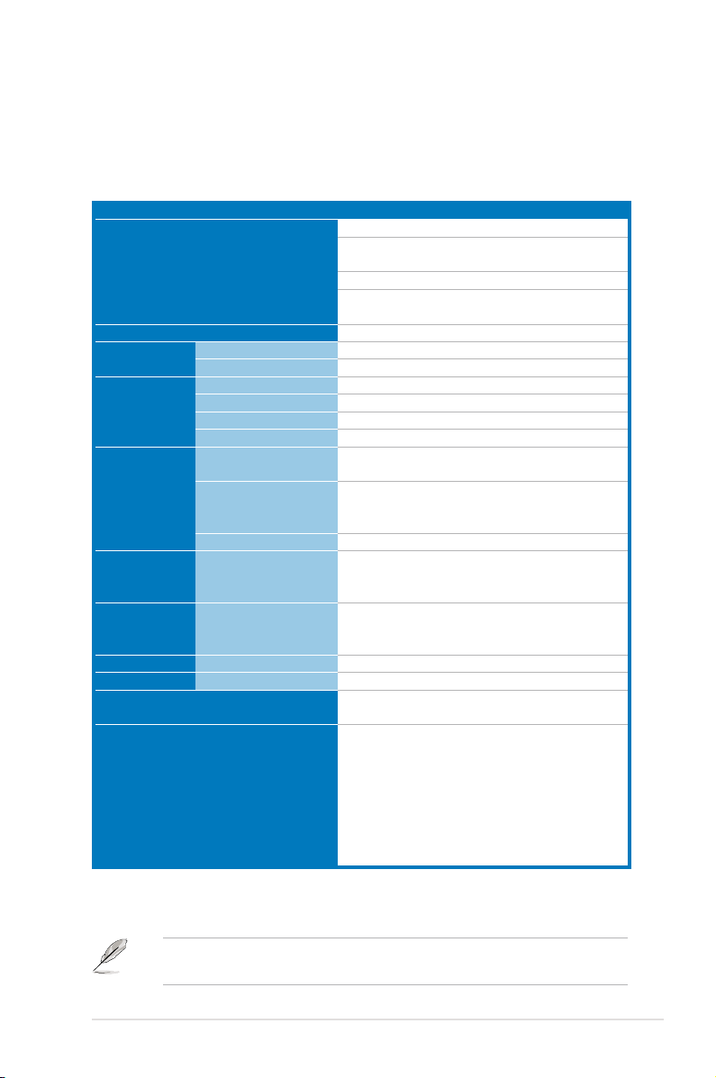
1.2 Systemspecications
The ASUS RS161-E5/PA2 is a 1U barebone server system featuring the ASUS
KFSN4-DRE motherboard. The server supports dual Socket-F(1207) 2000 Series
AMD Opteron™, plus other latest technologies through the chipsets onboard.
Model Name RS161-E5/PA2
Processor / System Bus
Core Logic
ASUS Features Smart Fan
Memory Total Slots
Expansion
Slots
HDD Bays I = internal
Networking LAN
Graphic VGA
Auxiliary Storage FDD / CD / DVD
Rear Panel
ASWM2.0
Capacity
Memory Type
Memory Size
Total PCI/PCI-X/PCI-E
Slots
Slot Type
Additional Slot 1
SATA Controller
A or S will be hotswappable
2 * Socket F (1207)
AMD Opteron™ 2000 series processor
(Barcelona Support)
Quad Core/Dual Core
HyperTransport™ Technology 1.0, 1GHz
512KB L2 cache/Per core, 2MB L3
nVIDIA nForce Professional 2200
Smart Fan II
√
16 (2-channel per CPU)
Maximum Up to 64GB
DDR2 533/667 Reg. ECC
512 MB, 1 GB, 2 GB, 4 GB
2
1 * PCI-E x16 slot (x8 link)
(Full-Heigh/Half-length)
1* PCI-E x16 slot (x8 link) (4.2" x 5.66")
1* SO-DIMM socket for optional ASMB3-SOL
nForce Professional 2200:
2 * SATA2 300MB/s ports
Support software RAID 0, 1 (Windows)
2 * Hot-Swap SATA2 HDDs
2 * Broadcom® BCM5721 PCI-E GbE LAN
XGI®Z9s VGA Controller / 32MB DDR2 VRAM
1 * 5.25" Optical Device Bay
Options: No Device / DVD-ROM / DVD-RW
1 * External Serial Port
2 * RJ-45 ports
1 * RJ-45 port for ASMB3 iKVM only
4 * USB 2.0 ports (Front * 2, Rear * 2)
1 * VGA port
1 * COM1
1 * PS/2 keyboard port
1 * PS/2 mouse port
(continued on the next page)
The RJ-45 port for ASMB3 iKVM is not for Ethernet connection and it functions
only when working with ASMB3 iKVM card.
ASUS RS161-E5/PA2 1-3
Page 14
OS Support
Anti-virus Software
Management
Solution
Software
Out of Band Remote
Management
Safety US / Canada
( UL1950-CSA950)
Europe (TUV / CE,
EN55022 compliance
to EU Directive 89 /
366/ EEC)
Europe (TUV)
EMI US (FCC, CFR47 Part
15, Class A)
Europe (CE, EN55022
& EN55024)
Australia (C-TICK)
Dimension
Net Weight Kg
(CPU, DRAM & HDD not included)
Power Supply
Environment
Windows® Server 2003 Enterprise R2 SP2
32/64-bit
RedHat® Enterprise Linux AS4.0 UP5 32/64-
bit
SuSE® Linux Enterprise Server 10 32/64-bit
Fedora core 7.0 32/64-bit
FreeBSD 6.2
(Subject to change without any notice)
Optional CA® eTrust™ 7.1 anti-virus software
ASWM2.0
Optional (ASMB3-SOL)
√
√
√
√
√
√
670mm * 444mm * 43.6mm
11.25Kg
500W Single Power Supply
Operation temperature: 10℃ ~ 35℃ /
Non operation temperature: -40℃ ~ 70℃
Non operation humidity: 20% ~ 90%
( Non condensing)
*Specications are subject to change without notice.
Refer to
Chapter 4 Motherboard Info
for details on the internal connectors.
Chapter 1: Product introduction1-4
Page 15
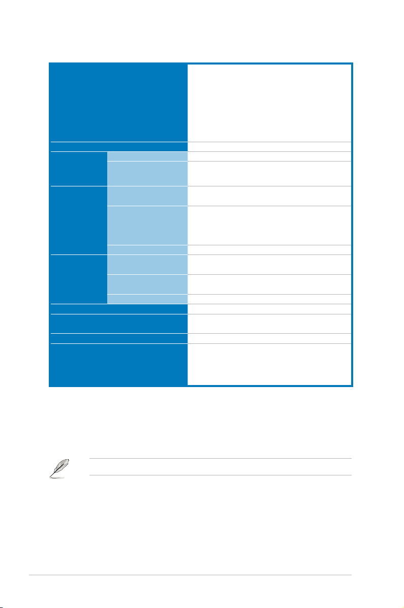
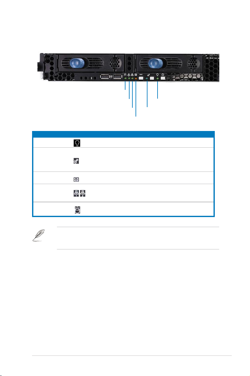
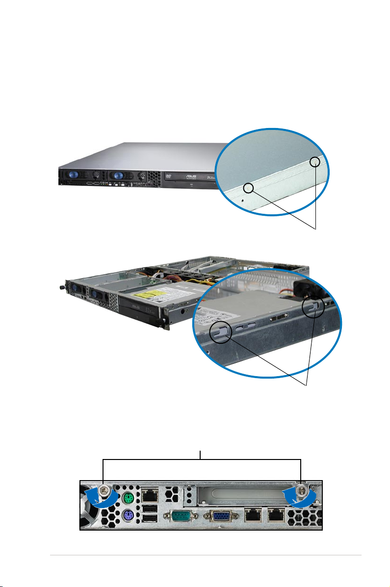
1.3 Front panel features
The barebone server displays a simple yet stylish front panel with easily accessible
features. The power and reset buttons, LED indicators, location switch, optical
drive, and two USB ports are located on the front panel.
Rack screw
Refer to
1.6.1 Front panel LEDs
Hot-swap HDD bay 1-2
USB ports System button and LED
for the LED descriptions.
Rack screw
Optical drive
HDD Access, LAN, Message LED
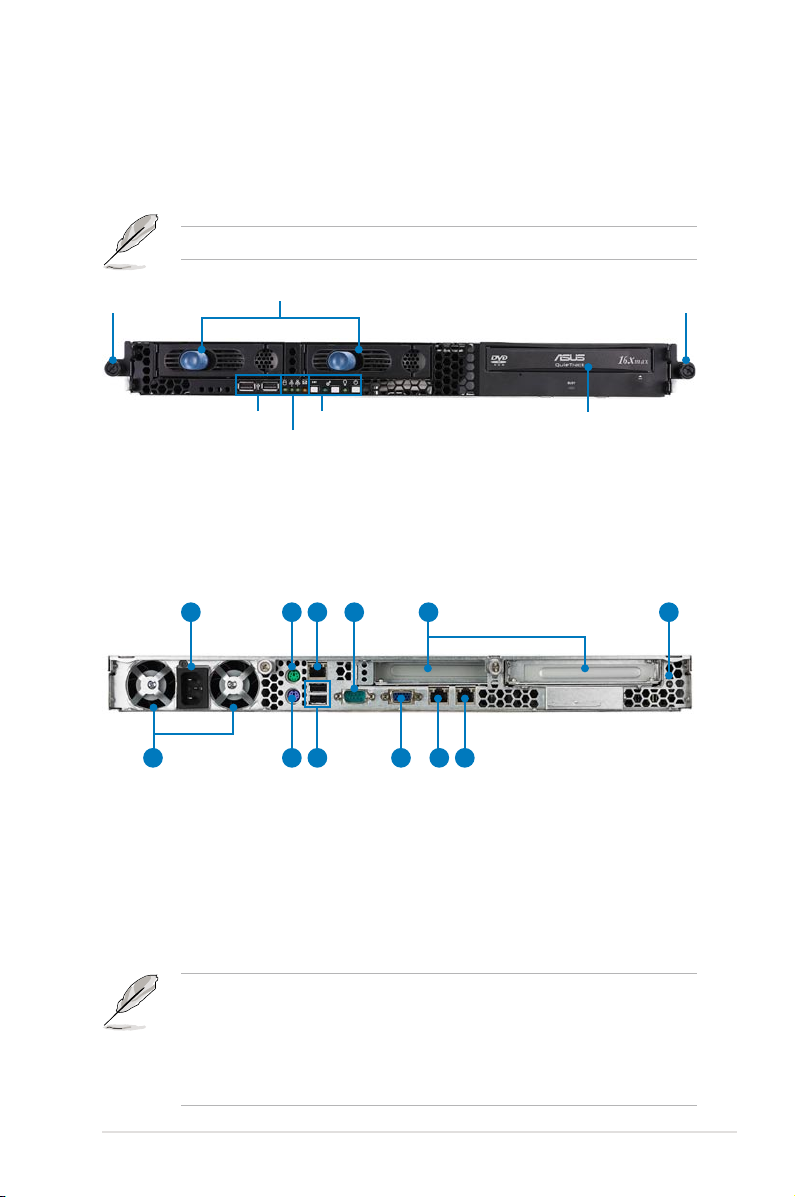
1.4 Rear panel features
The rear panel includes the expansion slot, system power socket, and PSU fans.
The middle part includes the I/O shield with openings for the rear panel connectors
on the motherboard.
1 2 4 5
12 11
1. AC power plug
2. PS/2 mouse port
3. LAN port for ASMB3 iKVM*
4. Serial port
5. Expansion slot
6. Rear location LED
3 6
10
9 8 7
7. LAN port1
8. LAN port2
9. VGA port
10. USB ports
11. PS/2 keyboard port
12. PSU fans
• The ports for the PS/2 keyboard, PS/2 mouse, USB, VGA, and Gigabit LAN
do not appear on the rear panel if motherboard is not present.
• Refer to
• The LAN port for ASMB3 iKVM functions only when you install ASMB3
ASUS RS161-E5/PA2 1-5
1.6.2 Rear panel LEDs
iKVM management card. Remove the mylar on the LAN port before using.
for the LED descriptions.
Page 16
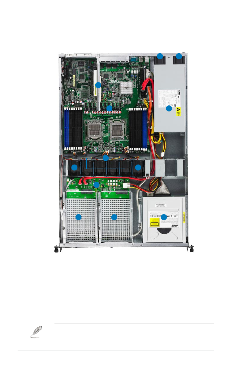
1.5 Internal features
The barebone server includes the basic components as shown.
1 1
6
2 3
4
5 5
7
8 9 10
1. PSU fans
2. ASUS KFSN4-DRE motherboard
3. Power supply
4. System fans (40mm x 28mm) x 4
5. Device fans (40mm x 28mm) x 2
6. 2 x PCI-E Slot (riser card)
7. SATA-II backplane
The air duct lies on top of the motherboard components. Remove the air duct to
access the components. Refer to section
for instructions.
air duct
8. Hot-swap HDD tray 1(port0)
9. Hot-swap HDD tray 2(Port1)
10. Optical drive
2.1.4 Removing and installing the
Chapter 1: Product introduction1-6
Page 17
1.6 LED information
1.6.1 Front panel LEDs
HDD Access LED
LAN2 LED
LAN1 LED
Message LED
LED Icon Display status Description
Power LED ON System power ON
Location LED
Message LED
LAN1/2 LEDs
Storage Access
LED
OFF
ON
OFF
Blinking
OFF
Blinking
ON
OFF
Blinking
Power LED
Location LED
Normal status
Location switch is pressed
(Press the location switch again to
turn off)
System is normal; no incoming event
ASWM indicates a HW monitor event
No LAN connection
LAN is transmitting or receiving data
LAN connection is present
No activity
Read/write data into the HDD
The location switch and LED are for service purposes. When the system fails
or is shut down, the server administrator can press either the front or the rear
location switch to identify the location of the specic system in a rack cabinet.
ASUS RS161-E5/PA2 1-7
Page 18
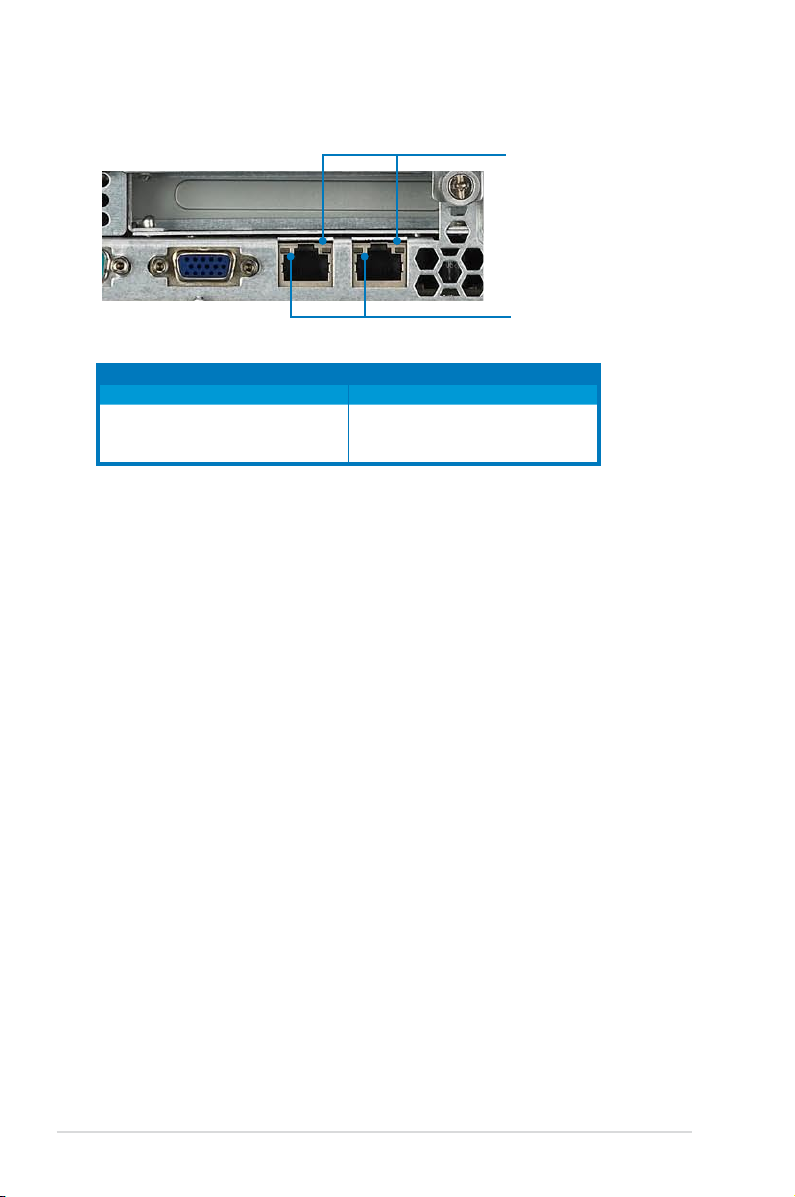
1.6.2 Rear panel LEDs
SPEED LED
ACT/LINK LED
ACT/LINK LED SPEED LED
Status Description Status Description
OFF No link OFF 10 Mbps connection
GREEN Linked ORANGE 100 Mbps connection
BLINKING Data activity GREEN 1 Gbps connection
Chapter 1: Product introduction1-8
Page 19

Chapter 2
This chapter lists the hardware setup
procedures that you have to perform
when installing or removing system
components.
ASUS RS161-E5/PA2
Hardware setup
2-
Page 20
2.1 Chassis cover
2.1.1 Removing the cover
1. Use a Phillips screwdriver to remove the screw on each front end of the top
cover.
2. Loosen the two thumbscrews on the rear panel to release the top cover from
the chassis.
Thumbscrews
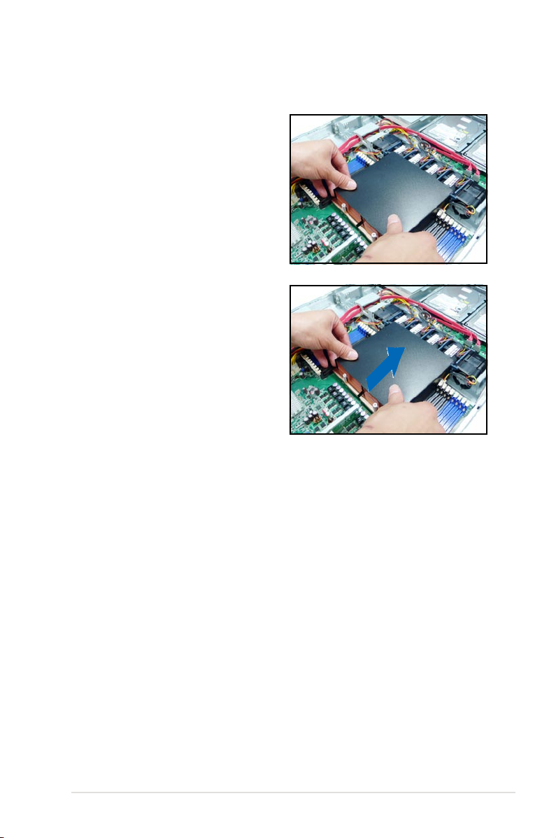
3. Firmly hold the cover and slide it
toward the rear panel for about half
an inch until it is disengaged from
the chassis.
4. Lift the cover from the chassis.
1/2 inch distance
Chapter 2: Hardware setup2-2
Page 21
2.1.2 Installing the cover
1. Position the cover on top of the chassis with the thumbscrews on the rear,
and leaving a gap of about half an inch from the front panel.
2. Make sure that the pegs inside the cover (two on each side) are aligned to
the grooves on the chassis.
Peg inside
3. Slide the cover toward the front until it snaps in place.
4. Tighten the thumbscrews on the rear to secure the cover.
Thumbscrews
Grooves
2-3ASUS RS161-E5/PA2
Page 22
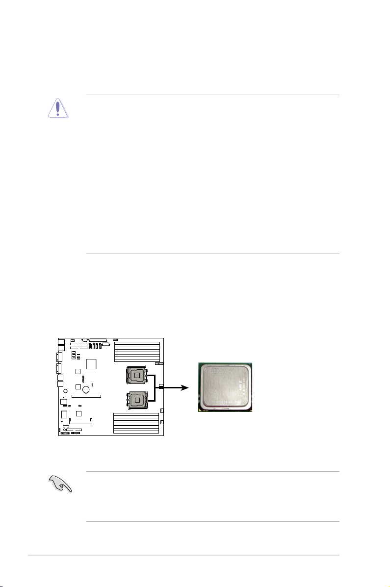
2.2 Central Processing Unit (CPU)
KFSN4-DRE
®
KFSN4-DRE CPU Socket 1207
CPU2
CPU1
The motherboard comes with a surface mount Socket F designed for the AMD®
Opteron® 2000 Series CPU in the Land Grid Array (LGA) package.
•
Upon purchase of the motherboard, make sure that the PnP cap is on
the socket and the socket contacts are not bent. Contact your retailer
immediately if the PnP cap is missing, or if you see any damage to the PnP
cap/socket contacts/motherboard components. ASUS will shoulder the cost
of repair only if the damage is shipment/transit-related.
•
Keep the cap after installing the motherboard. ASUS will process Return
Merchandise Authorization (RMA) requests only if the motherboard comes
with the cap on the CPU socket.
• Ensure to install identical CPUs to the system. DO NOT mix Quad-core and
Dual-core CPUs.
• When you install varying stepping and speed CPUs to the system, the
faster CPU downgrades and runs the speed as the slower one.
• The product warranty does not cover damage to the socket contacts
resulting from incorrect CPU installation/removal, or misplacement/loss/
incorrect removal of the PnP cap.
2.2.1 Installing the CPU
To install a CPU:
1. Locate the CPU socket on the motherboard.
• Before installing the CPU, make sure that the socket box is facing towards
you and the load lever is on your left.
• When installing only one CPU, install it in the CPU1 socket, or the CPU
warning LED will light.
Chapter 2: Hardware setup2-4
Page 23
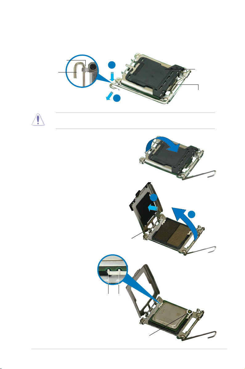
2. Press the load lever with your thumb (A), then move it to the left (B) until it is
released from the retention tab.
Retention tab
A
Load lever
B
To prevent damage to the socket pins, do not remove the PnP cap unless you
are installing a CPU.
3. Lift the load lever in the direction of
the arrow to a 135º angle.
4. Lift the load plate with your thumb
and forenger to a 100º angle (A),
then push the PnP cap from the
load plate window to remove (B).
PnP cap
This side of the socket
box should face you.
B
A
5. Position the CPU over
the socket, making
sure that the gold
triangle is on the
bottom-right corner
of the socket. The
socket alignment keys
should t into the
CPU notches.
Load plate
Alignment keys
Gold triangle mark
2-5ASUS RS161-E5/PA2
Page 24
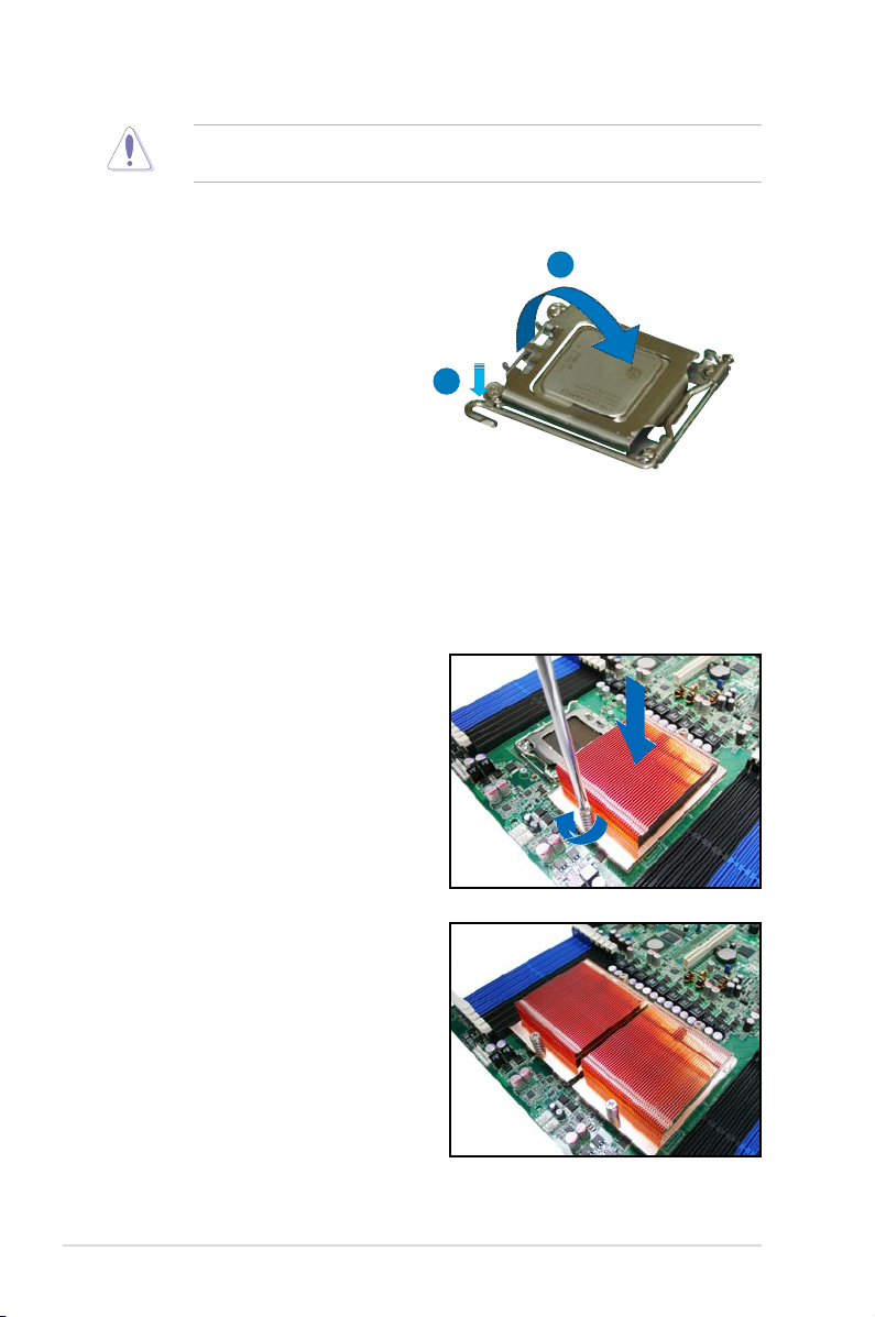
The CPU ts in only one correct orientation. DO NOT force the CPU into the
socket to prevent bending the connectors on the socket and damaging the CPU!
6. Close the load plate (A), then push
A
the load lever (B) until it snaps into
the retention tab.
B
2.2.2 Installing the CPU heatsink and airduct
To install the CPU heatsink:
1. Carefully place the heatsink on top
of the installed CPU and secure the
heatsink to the motherboard with a
Philips (cross) screwdriver.
2. Attach the other heatsink if you
install two CPUs on this system.
Chapter 2: Hardware setup2-6
Page 25
To install the airduct:
1. Position the airduct on top of the
heatsink.
2. Carefully lower the airduct until it ts
in place.
2-7ASUS RS161-E5/PA2
Page 26
KFSN4-DRE
®
KFSN4-DRE
240-pin DIMM sockets
112 Pins128 Pins
DIMM_B4
DIMM_A4
DIMM_B3
DIMM_A3
DIMM_B2
DIMM_A2
DIMM_B1
DIMM_A1
DIMM_C1
DIMM_D1
DIMM_C2
DIMM_D2
DIMM_C3
DIMM_D3
DIMM_C4
DIMM_D4
2.3 System memory
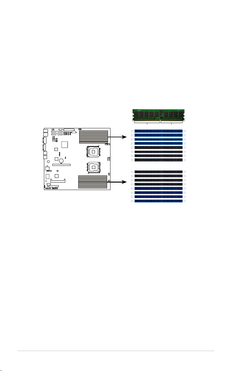
2.3.1 Overview
The motherboard comes with sixteen (16) Double Data Rate 2 (DDR2) Dual Inline
Memory Modules (DIMM) sockets.
A DDR2 module has the same physical dimensions as a DDR DIMM but has a
240-pin footprint compared to the 184-pin DDR DIMM. DDR2 DIMMs are notched
differently to prevent installation on a DDR DIMM socket.
The gure illustrates the location of the DDR2 DIMM sockets:
Chapter 2: Hardware setup2-8
Page 27
2.3.2 MemoryCongurations
You may install 256 MB, 512 MB, 1 GB, 2, or 4 GB registered ECC DDR2 DIMMs
into the DIMM sockets using the memory congurations in this section.
•
For dual-channel conguration, the total size of memory module(s) installed
per channel must be the same for better performance.
Single CPU:
DIMM_A1=DIMM_A2=DIMM_B1=DIMM_B2;
DIMM_A3=DIMM_A4=DIMM_B3=DIMM_B4
Dual CPU:
DIMM_A1=DIMM_A2=DIMM_B1=DIMM_B2=
DIMM_C1=DIMM_C2 =DIMM_D1=DIMM_D2;
DIMM_A3=DIMM_A4=DIMM_B3=DIMM_B4=
DIMM_C3=DIMM_C4 =DIMM_D3=DIMM_D4
•
Always install DIMMs with the same CAS latency. For optimum
compatibility, it is recommended that you obtain memory modules from the
same vendor.
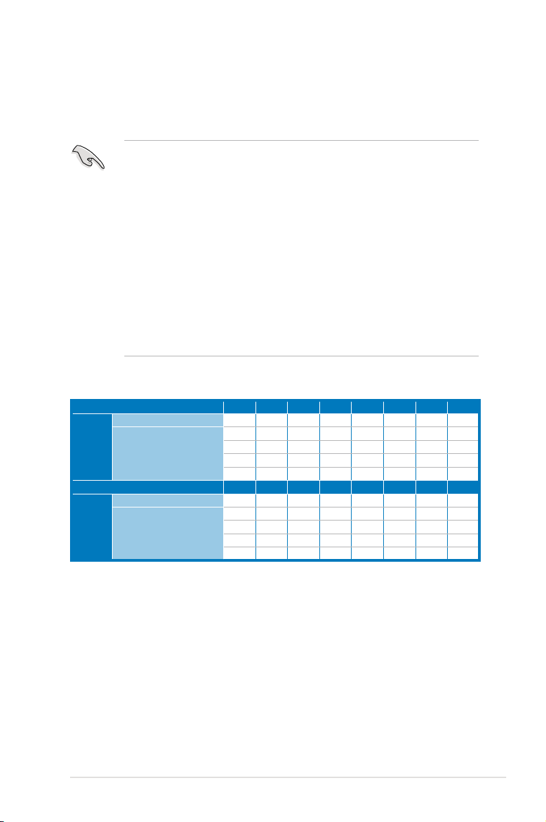
Memory population table
CPU1 SingleChannel
Dual Channel
CPU2 Single Channel
Dual Channel
A1 B1 A2 B2 A3 B3 A4 B4
•
• •
• • • •
• • • • • •
• • • • • • • •
C1 D1 C2 D2 C3 D3 C4 D4
•
• •
• • • •
• • • • • •
• • • • • • • •
2-9ASUS RS161-E5/PA2
Page 28
2.3.3 Installing a DIMM
Make sure to unplug the power supply before adding or removing DIMMs or
other system components. Failure to do so may cause severe damage to both
the motherboard and the components.
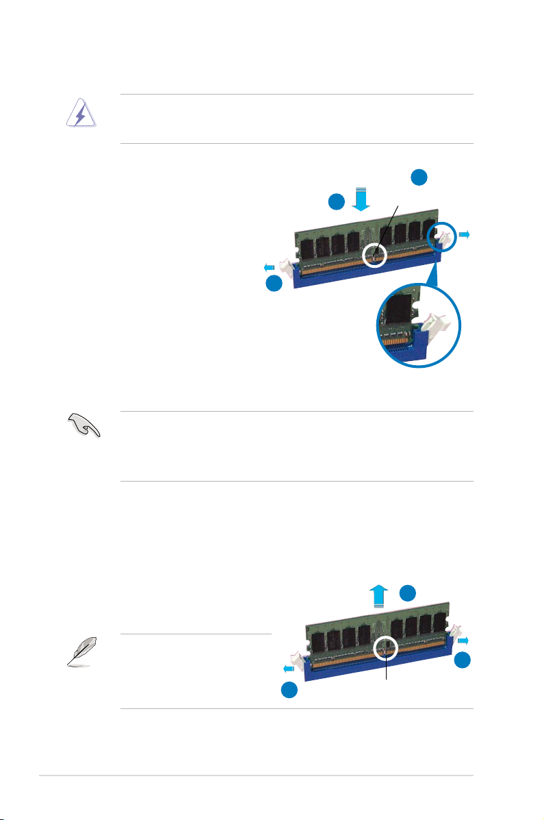
To install a DIMM:
1. Unlock a DIMM socket by
pressing the retaining clips
outward.
2. Align a DIMM on the socket
such that the notch on the
DIMM matches the break on the
socket.
3. Firmly insert the DIMM into the
socket until the retaining clips
snap back in place and the
DIMM is properly seated.
• A DDR2 DIMM is keyed with a notch so that it ts in only one direction. Do not
force a DIMM into a socket to avoid damaging the DIMM.
• The DDR2 DIMM sockets do not support DDR DIMMs. DO NOT install
DDR DIMMs to the DDR2 DIMM sockets.
2.3.4 Removing a DIMM
Follow these steps to remove a DIMM.
2
3
1
DDR2 DIMM notch
Unlocked retaining clip
1. Simultaneously press the retaining
clips outward to unlock the DIMM.
Support the DIMM lightly with
your ngers when pressing the
retaining clips. The DIMM might
get damaged when it ips out with
extra force.
2. Remove the DIMM from the socket.
2
1
1
DDR2 DIMM notch
Chapter 2: Hardware setup2-10
Page 29
2.4 Hard disk drives
The system supports two hot-swap Serial ATA hard disk drives. The hard disk drive
installed on the left tray connects to the motherboard SATA1 (Port0) port, while the
right tray hard disk drive connects to the motherboard SATA3 (Port2) port via the
SATA backplane.
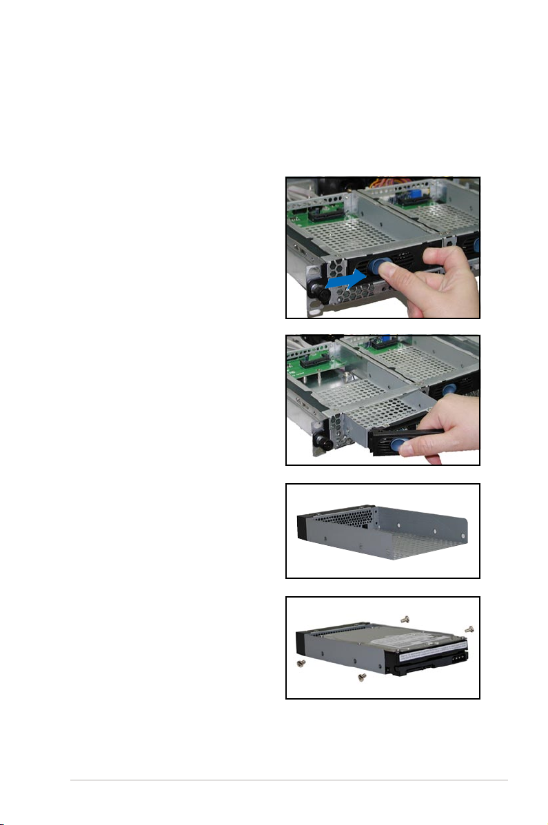
To install a hot-swap SATA HDD:
1. Release a drive tray by pushing the
spring lock to the right, then pulling
the tray lever outward. The drive
tray ejects slightly after you pull out
the lever.
2. Firmly hold the tray lever and pull
the drive tray out of the bay.
3. Take note of the drive tray holes.
Each side has three holes to t
different types of hard disk drives.
Use two screws on each side to
secure the hard disk drive.
4. Place a SATA hard disk drive on the
tray, then secure it with four screws.
2-11ASUS RS161-E5/PA2
Page 30
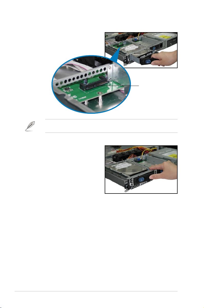
5. Carefully insert the drive tray and
push it all the way to the depth of
the bay until just a small fraction of
the tray edge protrudes.
When installed, the SATA connector on the drive connects to the SATA interface
on the backplane.
6. Push the tray lever until it clicks,
and secures the drive tray in place.
The drive tray is correctly placed
when its front edge aligns with the
bay edge.
7. Repeat steps 1 to 6 if you wish to
install a second SATA drive.
SATA interface
on the backplane
8. Connect the bundled SATA cables to the connectors on the SATA backplane.
Refer to section
2.7 SATA backplane cabling
for information on the SATA
backplane cable connections.
Chapter 2: Hardware setup2-12
Page 31

2.5 Expansion slot
2.5.1 Installing an expansion card to the
riser card bracket
The barebone server comes with a riser card bracket. You need to remove the
bracket if you want to install a PCI Express expansion cards.
To install a PCI-E card:
Your add-on card should be compliant with the PCI Express specication
requirement, or it might cause the system malfunction. Conrm with your vendor
before the installation.
1. Firmly hold the riser card bracket,
then pull it up to detach it from
the PCI Express slot on the
motherboard.
2. Place the riser card bracket on a
at and stable surface, then remove
the screw from the PCI-E x16 slot
bay.
3. Install a PCI-E card to the bracket
as shown, then secure the card
with a screw.
2-13ASUS RS161-E5/PA2
Page 32

2.5.2 Reinstalling the riser card bracket
To reinstall the riser card bracket:
1. Take note of the holes on the riser card bay. The three pegs on the riser card
bracket should match these holes to ensure that the bracket is properly in
place.
Pegs on the riser card
bracket
2. Install the riser card bracket with
the card into the PCI Express x16
slot on the motherboard.
3. Press the riser card bracket until
the golden connectors completely
t the slot and the bracket aligns
with the rear panel.
4. Connect the cable(s) to the card, if
applicable.
Chapter 2: Hardware setup2-14
Page 33

2.5.3 Conguringanexpansion card
After installing the expansion card, congure the it by adjusting the software
settings.
1. Turn on the system and change the necessary BIOS settings, if any. See
Chapter 5 for information on BIOS setup.
2. Assign an IRQ to the card. Refer to the following tables.
3. Install the software drivers for the expansion card.
Standard interrupt assignments
IRQ Priority Standard function
0 1 System Timer
1 2 Keyboard Controller
2 - Programmable Interrupt
3* 11 Communications Port (COM2)
4* 12 Communications Port (COM1)
5* 13 Sound Card (sometimes LPT2)
6 14 Floppy Disk Controller
7* 15 Printer Port (LPT1)
8 3 System CMOS/Real Time Clock
9* 4 ACPI Mode when used
10* 5 IRQ Holder for PCI Steering
11* 6 IRQ Holder for PCI Steering
12* 7 PS/2 Compatible Mouse Port
13 8 Numeric Data Processor
14* 9 Primary IDE Channel
15* 10 Secondary IDE Channel
*These IRQs are usually available for ISA or PCI devices.
2-15ASUS RS161-E5/PA2
Page 34

2.6 Cable connections
8
7
5
11
4
10
6
1
2
9
5
3
Pre-connected system cables
1. 24-pin SSI power connector (from power supply to motherboard)
2. 4-pin SSI power connector (power supply to motherboard)
3. SATA backplane power connector (from power supply)
4. Primary IDE connector (from motherboard to optical drive)
5. Device fan connector (from motherboard FRNT_FAN2&6 to device fans)
6. SATA connectors (from motherboard SATA 1-2 to SATA backplane board)
7. Panel connector (from motherboard to front I/O board)
8. Auxiliary panel connector (from motherboard to front I/O board)
9. USB connector (from motherboard to front I/O board)
10. PSUSMB1 connector (from power supply)
11. System fan connector (from motherboard FRNT_FAN 1/3/4/5 to system fans)
Chapter 2: Hardware setup2-16
Page 35

2.7 SATA backplane cabling
Connects the SMBus
cable from the MB
Connects the SATAII cable from
SATA2 on the MB
Connects the SATAII cable from
SATA1 on the MB
Connects a 4-pin plug from
power supply
Connect the SATAII HDDs
2-17ASUS RS161-E5/PA2
Page 36

2.8 Removable components
You may need to remove previously installed system components when installing
or removing system devices, or when you need to replace defective components.
This section tells how to remove the following components:
1. System fans
2. Device fan
3. Power supply module
4. Optical drive
5. Motherboard
2.8.1 System fans
The system comes with four units of 28 mm x 40 mm 15500 rpm fan with dummy
case. Refer to the illustration below for location of the system fans.
28 mm x 40 mm fan with dummy case
Incorrect installation of the system fan with dummy case may result to CPU
overheating and/or automatic system shutdown.
Chapter 2: Hardware setup2-18
Page 37

To uninstall the system fans:
1. Disconnect a system fan cable
from the fan connector on the
motherboard.
2. Lift the fan, then set aside.
3. Repeat step 1 to 2 to uninstall the
other system fans.
To reinstall the system fan:
1. Insert the fan to the fan cage. The
airow directional arrow on the
fan side should point towards the
system rear panel.
2. Connect the system fan cable to the
fan connector on the motherboard
(refer to
2.6 Cable connections
).
2-19ASUS RS161-E5/PA2
Page 38

2.8.2 System fan with dummy case
The system fan for the memory module(s) comes with a dummy case that allows it
to t in the fan cage.
To replace the system fan with dummy case:
1. Uninstall the fan following the instructions in the previous section.
2. Pull the dummy case to the direction of the arrow just enough to disengage
its pegs from the system fan.
Peg
3. Replace the system fan.
To reinstall the system fan with the dummy case:
1. Insert the dummy case pegs to the system fan holes until it ts in place.
2. Reinstall the system fan by following the instructions in the previous section.
Peg
Chapter 2: Hardware setup2-20
Page 39

2.8.3 Device fan
The system comes with two 28 mm * 40 mm (15500 rpm) device fans with dummy.
Refer to the illustration below for location of the device fans.
28 mm * 40 mm device fans
To uninstall the device fan:
1. Disconnect the device fan
cable from the connector on the
motherboard.
2. Lift the fan, then set aside.
1
2
To reinstall the device fan:
1. Insert the fan to the fan cage. The
airow directional arrow on the fan
side should point towards the rear
panel.
2. Connect the device fan cable
to the fan connector on the
motherboard.
1
2
2-21ASUS RS161-E5/PA2
Page 40

2.8.4 Power supply module
To uninstall the power supply module:
1. Disconnect all the power cables
connected to the motherboard and
other system devices.
2. Use a Phillips (cross) screwdriver
to remove the screws that secure
the front end of the power supply.
3. From the rear panel, remove two
screws that secure the power
supply from the chassis.
4. Slide the power supply forward for
about half an inch, then carefully lift
it out from the chassis.
Chapter 2: Hardware setup2-22
Page 41

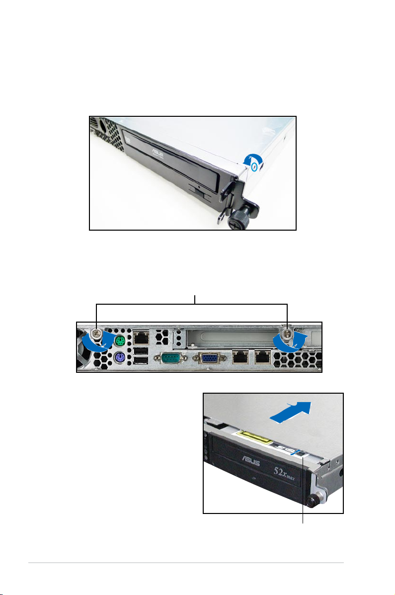
2.8.5 Optical drive
To uninstall the optical drive:
1. Disconnect the power and signal
cables connected to the rear of
the optical drive.
3. Pull out half of the drive tray to
remove the tray bezel.
2. Insert the optical drive emergency
eject pin to the emergency eject
pin hole until the drive tray ejects.
4. Pull the center of the bezel
outward (A), then lift the sides (B)
to remove.
Do not apply too much force when removing the bezel. Too much force may
break the drive tray!
5. Replace the drive tray.
2-23ASUS RS161-E5/PA2
Page 42

6. Remove two metal bracket screws and screws on the other side of the drive.
Keep the screws for later use.
7. Pull the metal bracket to the
direction of the arrow until its pegs
disengage from the drive holes.
8. Lift the metal bracket, then set
aside.
9. Push the drive inward, then lift it
out from the chassis.
10. Remove the metal rail on the
other side of the drive.
Chapter 2: Hardware setup2-24
Page 43

®
KFSN4-DRE
To reinstall the optical drive, follow the instructions in the previous chapter in a
reverse order.
When installing a new optical drive, make sure to remove the drive front panel
assembly and tray bezel before installing it to the chassis.
2.8.6 Motherboard
To uninstall the motherboard:
1. Disconnect all the pre-connected cables from the motherboard.
See section
2.6 Cable connections
for details.
2. Uninstall all the devices from the motherboard including the CPU and
heatsink, riser card bracket, and DDR DIMMs. Refer to the corresponding
sections for instructions on removing these components.
3. Use a Philips (cross) screwdriver to remove the screws that secure the
motherboard to the base of the chassis.
Refer to the illustration below for the location of the motherboard screws.
4. Carefully lift the motherboard out of
the chassis as shown.
2-25ASUS RS161-E5/PA2
Page 44

To reinstall the motherboard:
1. Firmly hold the motherboard by the
sides and insert it into the chassis
as shown.
2. Carefully adjust the motherboard
until the rear panel ports t in place.
3. Use a Phillips (cross) screwdriver to
secure the motherboard with ten (10)
screws in the holes as shown in the
illustration in the previous section.
4. Reconnect all the required cables
to the motherboard. See section
Cable connections
for details.
2.6
5. Reinstall all the devices that you
have previously removed.
Chapter 2: Hardware setup2-26
Page 45

Chapter 3
This chapter describes how to install
the optional components and devices
into the barebone server.
ASUS RS161-E5/PA2
Installation options
2-
Page 46

3.1 Rackmount rail kit items
If you have the rackmount rail kit, it contains two pairs of rails (one pair for each
side of the barebone system), and eight (8) pairs of nut-and-bolt type screws.
Nuts
Bolts
Left pair
Right pair
3.2 Rack rails assembly
To assemble the rack rails:
1. Determine the depth of the rack where you wish to install the system.
2. Match one long and one short rail to your desired length, and x them
together using four (4) pairs of nuts and bolts.
3. Repeat step 2 to assemble the other rail pair.
Rear ends
Bolts on inner side
Nuts on outer side
Front ends
Chapter 3: Installation options3-2
Page 47

3.3 Attaching the rails to the rack
To attach the rails to the rack:
1. Select one unit of space (1U) on the rack
where you wish to install the barebone
server.
2. Remove the screws from the 1U space on
the rack front.
3. Align the front end holes of a rack rail pair
to the 1U space.
4. Drive in two screws on the outer holes to
secure the front end.
1U space
5. Find the rear 1U space that corresponds to the front 1U space where you
attached the rail.
6. Remove the screws from the rear 1U space, and align the rear end holes.
7. Drive in two screws on the outer holes to secure the rear end.
8. From the rack front, nd the corresponding 1U space for the second rail pair.
9. Repeat steps 2 to 7 to attach the second rail pair. When properly installed,
the rack rails appear as shown.
3-3ASUS RS161-E5/PA2
Page 48

3.4 Rackmounting the server
To mount the server to the rack:
1. Firmly hold the server on both sides and insert the rear panel side to the front
end of the rack rail, then carefully push the server all the way to the back until
the front panel ts the front end of the rack, and the rack screws on the server
match the middle hole on the rack..
2. Tighten the two rack screws to
secure the server to the rack.
Rack screw
Chapter 3: Installation options3-4
Page 49

Chapter 4
This chapter includes the motherboard
layout, and brief descriptions of the
jumpers and internal connectors.
ASUS RS161-E5/PA2
Motherboard info
Page 50

AMI
8Mb
FWH
®
FLOPPY1
BUZZ1
COM2
Super
I/O
CR2032 3V
Lithium Cell
CMOS Power
PANEL1
PS/2
T: Mouse
B: Keyboard
USB1
USB2
ATX12V1
nForce
Professional
2200
PSUSMB1
HDLED1
AUX_PANEL1
USB34
KFSN4-DRE
33cm (13in)
30.5cm (12in)
COM1
VGA1
PRI_IDE1
CLRTC1
RECOVERY1
VGA_EN1
REAR_FAN1
FRNT_FAN5
LAN2
ATXPWR1
XGI
Z9S
PCIE1
MEM_WARN1
BCM
5721
LAN1
REAR_FAN2
REAR_FAN3
REAR_FAN4
DDR2 DIMM_B4 (64/72 bit, 240-pin module)
DDR2 DIMM_A4 (64/72 bit, 240-pin module)
DDR2 DIMM_B3 (64/72 bit, 240-pin module)
DDR2 DIMM_A3 (64/72 bit, 240-pin module)
DDR2 DIMM_B2 (64/72 bit, 240-pin module)
DDR2 DIMM_A2 (64/72 bit, 240-pin module)
DDR2 DIMM_B1 (64/72 bit, 240-pin module)
DDR2 DIMM_A1 (64/72 bit, 240-pin module)
DDR2 DIMM_C1 (64/72 bit, 240-pin module)
DDR2 DIMM_D1 (64/72 bit, 240-pin module)
DDR2 DIMM_C2 (64/72 bit, 240-pin module)
DDR2 DIMM_D2 (64/72 bit, 240-pin module)
DDR2 DIMM_C3 (64/72 bit, 240-pin module)
DDR2 DIMM_D3 (64/72 bit, 240-pin module)
DDR2 DIMM_C4 (64/72 bit, 240-pin module)
DDR2 DIMM_D4 (64/72 bit, 240-pin module)
SATA3
SATA4
SATA1
SATA2
SEC_IDE1
CPU1
CPU2
FRNT_FAN6
FRNT_FAN4
FRNT_FAN3
FRNT_FAN1
BCM
5721
CPU_WARN1
FAN_SEL1
LAN1_EN1
LAN2_EN1
BMCSOCKET1
FRNT_FAN2
SB_PWR1
J1
4.1 Motherboard layout
Chapter 4: Motherboard information4-2
Page 51

Layout contents
Onboard LED Page
1. Standby Power LED 4-4
2. CPU warning LED (CPU_WARN1)
3. Memory warning LED (MEM_WARN1)
Jumpers Page
1. Clear RTC RAM (CLRTC1) 4-5
2. Gigabit LAN1 controller setting (3-pin LAN1_EN1, LAN2_EN1)
3. VGA Graphics controller setting (3-pin VGA_EN1)
4. Fan control setting (3-pin FAN_SEL1)
5. Force BIOS recovery setting (3-pin RECOVERY1) 4-8
Internal connectors Page
1. Floppy disk drive connector (34-1 pin FLOPPY1) 4-8
2.
3.
4.
5. USB connectors (10-1 pin USB34)
6.
(4-pin FRNT_FAN1/2/3/4, REAR_FAN1/2/3/4/5/6)
7.
8.
9.
10. LPC debug card connector (14-1 pin LPC1)
11.
12. System panel connector (20-1 pin PANEL1) 4-15
IDE connectors (40-1 pin PRI_IDE1, SEC_IDE1) 4-8
Serial ATA connectors (7-pin SATA1, SATA2, SATA3, SATA4) 4-9
Hard disk activity LED connector (4-pin HDLED1) 4-10
Front and rear fan connectors
Serial port connectors (10-1 pin COM2) 4-11
ATX power connectors (24-pin ATXPWR1, 8-pin ATX12V1) 4-12
Power supply SMBus connector (5-pin PSUSMB1) 4-12
Auxiliary panel connector (20-2 pin AUX_PANEL1) 4-14
4-4
4-4
4-6
4-6
4-7
4-10
4-11
4-13
ASUS RS161-E5/PA2 4-3
Page 52

4.2 Onboard LED
KFSN4-DRE
®
KFSN4-DRE Onboard LED
ON OFF
MEM_WARN1
Abnormal
Normal
(green)
ON OFF
CPU_WARN1
Abnormal
Normal
(green)
KFSN4-DRE
®
KFSN4-DRE Standby power LED
SB_PWR1
ON
Standby
Power
OFF
Powered
Off
1. Standby Power LED
The motherboard comes with a standby power LED. The green LED lights up
to indicate that the system is ON, in sleep mode, or in soft-off mode. This is a
reminder that you should shut down the system and unplug the power cable
before removing or plugging in any motherboard component. The illustration
below shows the location of the onboard LED
2. CPU warning LED (CPU_WARN1)
The CPU warning LED lights up to indicate that a processor is not installed or
the processor is not installed properly in CPU 1 socket.
3. Memory warning LED (MEM_WARN1)
The memory warning LED lights up to indicate that there is no power in the
memory DIMMs.
Chapter 4: Motherboard information4-4
Page 53

4.3 Jumpers
KFSN4-DRE
®
KFSN4-DRE Clear RTC RAM
CLRTC1
Normal
(Default)
Clear CMOS
1
2
3
2
1. Clear RTC RAM (CLRTC1)
This jumper allows you to clear the Real Time Clock (RTC) RAM in CMOS.
You can clear the CMOS memory of date, time, and system setup parameters
by erasing the CMOS RTC RAM data. The onboard button cell battery
powers the RAM data in CMOS, which include system setup information such
as system passwords.
To erase the RTC RAM:
1. Turn OFF the computer and unplug the power cord.
2. Remove the onboard battery.
3. Move the jumper cap from pins 1-2 (default) to pins 2-3. Keep the cap on
pins 2-3 for about 5~10 seconds, then move the cap back to pins 1-2.
4. Reinstall the battery.
5. Plug the power cord and turn ON the computer.
6. Hold down the <Del> key during the boot process and enter BIOS setup
to re-enter data.
Except when clearing the RTC RAM, NEVER remove the cap on CLRTC jumper
default position. Removing the cap will cause system boot failure!
ASUS RS161-E5/PA2 4-5
Page 54

2. Gigabit LAN1 controller setting (3-pin LAN1_EN1, LAN2_EN1)
KFSN4-DRE
®
KFSN4-DRE LAN setting
LAN1_EN1
Enable
(Default)
Disable
LAN2_EN1
Enable
(Default)
Disable
2 31 2
2 31 2
KFSN4-DRE
®
KFSN4-DRE VGA setting
VGA_EN1
Enable
(Default)
Disable
2 31 2
These jumpers allow you to enable or disable the onboard Broadcom
®
BCM5721 Gigabit LAN1/2 controller. Set to pins 1-2 to activate the Gigabit
LAN feature.
3. VGA Graphics controller setting (3-pin VGA_EN1)
This jumper allows you to enable or disable the onboard ATI ES1000 video
graphics controller. Set to pins 1-2 to enable the video graphics controller.
Chapter 4: Motherboard information4-6
Page 55

4. Fan control setting (3-pin FAN_SEL1)
KFSN4-DRE
®
KFSN4-DRE FAN setting
FAN_SEL1
1 2 2 3
4-PIN FAN
(Default)
3-PIN FAN
This jumper allows you to switch for fan pin selection. Set to pins 1-2 for 4-pin
fans or pins 2-3 for 3-pin fans.
• If you use a 4-pin fan but set the jumper to pin 2-3, the fan you installed
may not work.
• If you use a 3-pin fan but set the jumper for a 4-pin fan, the fan controll will
not work and the fan you installed will always run at full speed.
ASUS RS161-E5/PA2 4-7
Page 56

5. Force BIOS recovery setting (3-pin RECOVERY1)
KFSN4-DRE
®
KFSN4-DRE BIOS recovery setting
RECOVERY1
Disable
(Default)
Enable
2 31 2
This jumper allows you to quickly update or recover the BIOS settings when it
becomes corrupted.
To update the BIOS:
1. Prepare a oppy disk that contains the latest BIOS for the motherboard
and the Afudos utility. Make sure you download the correct BIOS for your
motherboard model.
2. Set the jumper to pins 2-3.
3. Insert the oppy disk then turn on the system to update the BIOS.
4. Shut down the system.
5. Set the jumper back to pins 1-2.
6. Turn on the system.
Chapter 4: Motherboard information4-8
Page 57

4.4 Internal connectors
KFSN4-DRE
®
NOTE: Orient the red markings on
the floppy ribbon cable to PIN 1.
PIN 1
FLOPPY1
KFSN4-DRE Floppy disk drive connector
KFSN4-DRE
®
KFSN4-DRE IDE connector
NOTE: Orient the red markings
(usually zigzag) on the IDE
ribbon cable to PIN 1.
SEC_IDE1
PRI_IDE1
PIN 1
PIN 1
1. Floppy disk drive connector (34-1 pin FLOPPY1)
This connector is for the provided oppy disk drive (FDD) signal cable. Insert
one end of the cable to this connector, then connect the other end to the
signal connector at the back of the oppy disk drive.
2. IDE connectors (40-1 pin PRI_IDE1, SEC_IDE1)
The onboard IDE connectors are for Ultra DMA 133/100/66 signal cables.
ASUS RS161-E5/PA2 4-9
Page 58

3. Serial ATA connectors (7-pin SATA1, SATA2, SATA3, SATA4)
KFSN4-DRE
®
SATA2
KFSN4-DRE SATA connectors
GND
RSATA_TXP2
RSATA_TXN2
GND
RSATA_RXN2
RSATA_RXP2
GND
SATA1
GND
RSATA_TXP1
RSATA_TXN1
GND
RSATA_RXN1
RSATA_RXP1
GND
SATA4
GND
RSATA_TXP4
RSATA_TXN4
GND
RSATA_RXN4
RSATA_RXP4
GND
SATA3
GND
RSATA_TXP3
RSATA_TXN3
GND
RSATA_RXN3
RSATA_RXP3
GND
Supported by the NVIDIA® nForce Professional 2200 chipset, these
connectors are for the Serial ATA signal cables for Serial ATA hard disk drives
that allows up to 3Gb/s of data transfer rate.
If you installed Serial ATA hard disk drives, you can create a RAID 0, RAID 1,
RAID 1+0, RAID 5, or JBOD conguration.
The actual data transfer rate depends on the speed of Serial ATA hard disks
installed.
Chapter 4: Motherboard information4-10
Page 59

4. Hard disk activity LED connector (4-pin HDLED1)
KFSN4-DRE
®
KFSN4-DRE storage card activity LED connector
HDLED1
PIN1
ADD_IN_CARDNC
NC
ADD_IN_CARD-
KFSN4-DRE
®
KFSN4-DRE USB connector
USB34
Power
PIN1
USB PortA(-)
USB PortA(+)
GND
Power
USB PortB(-)
USB PortB(+)
GND
NC
This connector is for the storage add-on card cable connected to the SCSI or
SATA add-on card. The read or write activities of any device connected to the
SCSI or SATA add-on card causes the front panel LED to light up.
5. USB connector (10-1 pin USB34)
This connector is for USB 2.0 ports. Connect the USB module cable to
this connector, then install the module to a slot opening at the back of the
system chassis. This USB connector complies with USB 2.0 specication that
supports up to 480 Mbps connection speed.
ASUS RS161-E5/PA2 4-11
Page 60

6. Front and rear fan connectors (3-pin FRNT_FAN1, FRNT_FAN2, FRNT_
KFSN4-DRE
®
KFSN4-DRE Fan connectors
FRNT_FAN1
FRNT_FAN6
FRNT_FAN5
REAR_FAN4
REAR_FAN3
REAR_FAN2
REAR_FAN1
GND
FAN Power
FAN Speed
PWM Control
FRNT_FAN4
FRNT_FAN3
FRNT_FAN1
FRNT_FAN2
GND
FAN Power
FAN Speed
PWM Control
REAR_FAN4
GND
FAN Power
FAN Speed
PWM Control
REAR_FAN3
GND
FAN Power
FAN Speed
PWM Control
REAR_FAN2
GND
FAN Power
FAN Speed
PWM Control
REAR_FAN1
FRNT_FAN2
GND
FAN Power
FAN Speed
PWM Control
GND
FAN Power
FAN Speed
PWM Control
FRNT_FAN4
GND
FAN Power
FAN Speed
PWM Control
FRNT_FAN3
GND
FAN Power
FAN Speed
PWM Control
REAR_FAN6
GND
FAN Power
FAN Speed
PWM Control
REAR_FAN5
KFSN4-DRE
®
KFSN4-DRE Serial port connector
PIN1
COM2
FAN3, FRNT_FAN4, REAR_FAN1, REAR_FAN2, REAR_FAN3, REAR_
FAN4, REAR_FAN5, REAR_FAN6)
The fan connectors support cooling fans of 350mA~2000mA (24 W max.) or
a total of 1A~3.48A (41.76 W max.) at +12V. Connect the fan cables to the
fan connectors on the motherboard, making sure that the black wire of each
cable matches the ground pin of the connector.
• DO NOT forget to connect the fan cables to the fan connectors. Insufcient
air ow inside the system may damage the motherboard components.
These are not jumpers! DO NOT place jumper caps on the fan connectors!
• All fans feature the ASUS Smart Fan technology.
7. Serial port connector (10-1 pin COM2)
This connector is for a serial (COM) port. Connect the serial port module
cable to this connector, then install the module to a slot opening at the back
of the system chassis.
Chapter 4: Motherboard information4-12
Page 61

8. ATX power connectors (24-pin ATXPWR1, 8-pin ATX12V1)
KFSN4-DRE
®
KFSN4-DRE ATX power connectors
8-pin
GND12V2
GND12V2
GND12V1
GND12V1
24-pin Power Connector
ATXPWR1
ATX12V1
+3 Volts
+3 Volts
Ground
+5 Volts
+5 Volts
Ground
Ground
Power OK
+5V Standby
+12 Volts
-5 Volts
+5 Volts
+3 Volts
-12 Volts
Ground
Ground
Ground
PSON#
Ground
+5 Volts
+12 Volts
+3 Volts
+5 Volts
Ground
These connectors are for an ATX power supply plugs. The power supply
plugs are designed to t these connectors in only one orientation. Find the
proper orientation and push down rmly until the connectors completely t.
•
DO NOT forget to connect the 8-pin ATX +12 V power plug; otherwise, the
system will not boot.
• Use of a PSU with a higher power output is recommended when
conguring a system with more power-consuming devices. The system
may become unstable or may not boot up if the power is inadequate.
• Make sure that your power supply unit (PSU) can provide at least the
minimum power required by your system. See the table below for details.
ASUS RS161-E5/PA2 4-13
Page 62

KFSN4-DRE
®
+3.3V
PIN1
+3.3V +3.3V
GND GND
LPC_LAD2 LPC_LAD3
LPC_LAD0 LPC_LAD1
PLTRST LFRAME_N
CLK GND
KFSN4-DRE LPC debug card connector
J1
9. Power Supply SMBus connector (5-pin PSUSMB1)
KFSN4-DRE
®
KFSN4-DRE Power supply SMBus connector
PSUSMB1
+3.3V Remote Sense
GND
NC
I2C_7_DATA#
I2C_7_CLK#
This connector allows you to connect SMBus (System Management Bus) to
the power supply unit to read PSU information. Devices communicate with an
SMBus host and/or other SMBus devices using the SMBus interface.
10. LPC debug card connector (14-1 pin LPC1)
This is a low pin count interface used to plug in the LPC debug card.
Chapter 4: Motherboard information4-14
Page 63

11. Auxiliary panel connector (20-2 pin AUX_PANEL1)
KFSN4-DRE
®
KFSN4-DRE Auxiliary panel connector
AUX_PANEL1
I2C_4_DATA#LOCATORLED1+
+5VSBLOCATORLED1-
LAN1_LINKLOCATORBTN#
LAN1_ACTGND
+5VSB
I2C_4_CLK#
GNDGND
LAN2_ACTLOCATORLED2-
LAN2_LINKLOCATORLED2+
CASEOPEN
PIN1
NC
1 2 2
5 43 4
This connector supports several server system functions.
1. Front Panel SMBus (6-1 pin)
This connector allows you to connect SMBus (System Management Bus)
devices to the system front panel. Devices communicate with an SMBus host
and/or other SMBus devices using the SMBus interface.
2. LAN1 link activity LED (2-pin LAN1_LINKACTLED)
This 2-pin connector is for the LAN1 Activity LED. Connect the LAN1 Activity
LED cable to this connector. This LED blinks during a network activity and is
always lit when linked.
3. LAN2 link activity LED (2-pin LAN2_LINKACTLED)
This 2-pin connector is for the LAN2 Activity LED. Connect the LAN2 Activity
LED cable to this connector. This LED blinks during a network activity and
lights up when linked.
4. Chassis Intrusion connector (3-pin CASEOPEN)
This lead is for a chassis with an intrusion detection feature. This requires
an external detection mechanism such as a chassis intrusion sensor or
microswitch. When you remove any chassis component, the sensor triggers
and sends a high-level signal to this lead to record a chassis intrusion event.
5. Locator LED 1 (2-pin LOCATORLED1)
This 2-pin connector is for the Locator LED 1. Connect the Locator LED
1 cable to this connector. This LED lights up when the Locator button is
pressed.
6. Locator Button/Switch (2-pin LOCATORBTN)
This connector is for the locator button. This button queries the state of the
system locator.
7. Locator LED 2 (2-pin LOCATORLED2)
This 2-pin connector is for the Locator LED 2. Connect the Locator LED 2
cable to this connector.
ASUS RS161-E5/PA2 4-15
Page 64

12. System panel connector (20-1 pin PANEL1)
KFSN4-DRE
®
PANEL1
Message LED-GND
NCPOWERBTN#
+5VGND
GNDNC
POWERLED+IDELED+
NCIDELED-
POWERLED-
Message LED+NMI button
GNDRESETBTN#
SPKROUTGND
1 342
65
KFSN4-DRE System panel connector
This connector supports several chassis-mounted functions.
The system panel connector is color-coded for easy connection. Refer to the
connector description below for details.
1.
System power LED (Green 3-pin PLED)
This 3-pin connector is for the system power LED. Connect the chassis
power LED cable to this connector. The system power LED lights up
when you turn on the system power, and blinks when the system is in
sleep mode.
2.
Message LED (Brown 2-pin MLED)
This 2-pin connector is for the message LED cable that connects to the
front message LED. The message LED shows the hardware status and
is controlled by ASWM software. This function only works under the
operating system installed ASWM.
3.
System warning speaker (Orange 4-pin SPEAKER)
This 4-pin connector is for the chassis-mounted system warning
speaker. The speaker allows you to hear system beeps and warnings.
4.
Hard disk drive activity LED (Red 2-pin IDE_LED)
This 2-pin connector is for the HDD Activity LED. Connect the HDD
Activity LED cable to this connector. The IDE LED lights up or ashes
when data is read from or written to the HDD.
5.
ATX power button/soft-off button (Green 2-pin PWRSW)
This connector is for the system power button. Pressing the power
button turns the system on or puts the system in sleep or soft-off mode
depending on the BIOS settings. Pressing the power switch for more
than four seconds while the system is ON turns the system OFF.
6.
Reset button (Blue 2-pin RESET)
This 2-pin connector is for the chassis-mounted reset button for system
reboot without turning off the system power.
Chapter 4: Motherboard information4-16
Page 65

Chapter 5
This chapter tells how to change the
system settings through the BIOS Setup
menus. Detailed descriptions of the BIOS
parameters are also provided.
ASUS RS161-E5/PA2 5-1
BIOS setup
Page 66

5.1 Managing and updating your BIOS
The following utilities allow you to manage and update the motherboard Basic
Input/Output System (BIOS) setup.
1.
ASUS AFUDOS (Updates the BIOS using a bootable oppy disk)
ASUS CrashFree BIOS 2 (Updates the BIOS using a bootable oppy disk or
2.
the motherboard support CD when the BIOS le fails or gets corrupted.)
Refer to the corresponding sections for details on these utilities.
Save a copy of the original motherboard BIOS le to a bootable oppy disk or
USB ash disk in case you need to restore the BIOS in the future. Copy the
original motherboard BIOS using the ASUS Update or AFUDOS utilities.
5.1.1 Creatingabootableoppydisk
1. Do either one of the following to create a bootable oppy disk.
DOS environment
a. Insert a 1.44MB oppy disk into the drive.
format
b. At the DOS prompt, type
Windows® XP environment
a. Insert a 1.44 MB oppy disk to the oppy disk drive.
b. Click
c. Select the 3½ Floppy Drive icon.
d. Click
e. Select
Start from the Windows® desktop, then select My Computer.
File from the menu, then select Format. A Format 3½ Floppy Disk
window appears.
Create an MS-DOS startup disk from the format options eld,
then click Start.
A:/S then press <Enter>.
2. Copy the original or the latest motherboard BIOS le to the bootable oppy
disk.
5-2 Chapter 5: BIOS setup
Page 67

5.1.2 AFUDOS utility
The AFUDOS utility allows you to update the BIOS le in DOS environment using
a bootable oppy disk with the updated BIOS le. This utility also allows you to
copy the current BIOS le that you can use as backup when the BIOS fails or gets
corrupted during the updating process.
Copying the current BIOS
To copy the current BIOS le using the AFUDOS utility:
• Make sure that the oppy disk is not write-protected and has at least
1024KB free space to save the le.
• The succeeding BIOS screens are for reference only. The actual BIOS
screen displays may not be same as shown.
1. Copy the AFUDOS utility (afudos.exe) from the motherboard support CD to
the bootable oppy disk you created earlier.
2. Boot the system in DOS mode, then at the prompt type:
afudos /o[lename]
where the [lename] is any user-assigned lename not more than eight
alphanumeric characters for the main lename and three alphanumeric
characters for the extension name.
A:\>afudos /oOLDBIOS1.rom
Mainlename Extension name
3. Press <Enter>. The utility copies the current BIOS le to the oppy disk.
A:\>afudos /oOLDBIOS1.rom
AMI Firmware Update Utility - Version 1.19(ASUS V2.07(03.11.24BB))
Copyright (C) 2002 American Megatrends, Inc. All rights reserved.
Reading ash ..... done
Write to le...... ok
A:\>
The utility returns to the DOS prompt after copying the current BIOS le.
UpdatingtheBIOSle
To update the BIOS le using the AFUDOS utility:
1. Visit the ASUS website (www.asus.com) and download the latest BIOS le for
the motherboard. Save the BIOS le to a bootable oppy disk.
ASUS RS161-E5/PA2 5-3
Page 68

Write the BIOS lename on a piece of paper. You need to type the exact BIOS
lename at the DOS prompt.
2. Copy the AFUDOS utility (afudos.exe) from the motherboard support CD to
the bootable oppy disk you created earlier.
3. Boot the system in DOS mode, then at the prompt type:
afudos /i[lename]
where [lename] is the latest or the original BIOS le on the bootable oppy
disk.
A:\>afudos /iKFSN4DRE.ROM
4. The utility veries the le and starts updating the BIOS.
A:\>afudos /iKFSN4DRE.ROM
AMI Firmware Update Utility - Version 1.19(ASUS V2.07(03.11.24BB))
Copyright (C) 2002 American Megatrends, Inc. All rights reserved.
WARNING!! Do not turn off power during ash BIOS
Reading le ....... done
Reading ash ...... done
Advance Check ......
Erasing ash ...... done
Writing ash ...... 0x0008CC00 (9%)
DO NOT shut down or reset the system while updating the BIOS to prevent
system boot failure!
5. The utility returns to the DOS prompt after the BIOS update process is
completed. Reboot the system from the hard disk drive.
A:\>afudos /iKFSN4DRE.ROM
AMI Firmware Update Utility - Version 1.19(ASUS V2.07(03.11.24BB))
Copyright (C) 2002 American Megatrends, Inc. All rights reserved.
WARNING!! Do not turn off power during ash BIOS
Reading le ....... done
Reading ash ...... done
Advance Check ......
Erasing ash ...... done
Writing ash ...... done
Verifying ash .... done
Please restart your computer
A:\>
5-4 Chapter 5: BIOS setup
Page 69

5.1.3 ASUS CrashFree BIOS 2 utility
The ASUS CrashFree BIOS 2 is an auto recovery tool that allows you to restore
the BIOS le when it fails or gets corrupted during the updating process. You can
update a corrupted BIOS le using the CD or the oppy disk that contains the
updated BIOS le.
• Prepare the CD or the oppy disk containing the updated motherboard
BIOS before using this utility.
• Make sure that you rename the original or updated BIOS le in the CD or
oppy disk to KFSN4-DRE.ROM.
RecoveringtheBIOSfromaoppydisk
To recover the BIOS from a oppy disk:
1. Turn on the system.
2. Insert the oppy disk with the original or updated BIOS le to the oppy disk
drive.
3. The utility displays the following message and automatically checks the
oppy disk for the original or updated BIOS le.
Bad BIOS checksum. Starting BIOS recovery...
Checking for oppy...
When found, the utility reads the BIOS le and starts ashing the corrupted
BIOS le.
Bad BIOS checksum. Starting BIOS recovery...
Checking for oppy...
Floppy found!
Reading le “KFN4DRE.ROM”. Completed.
Start ashing...
DO NOT shut down or reset the system while updating the BIOS! Doing so can
cause system boot failure!
4. Restart the system after the utility completes the updating process.
ASUS RS161-E5/PA2 5-5
Page 70

5.2 BIOS setup program
This motherboard supports a programmable Serial Peripheral Interface (SPI) chip
that you can update using the provided utility described in section 5.1 Managing
and updating your BIOS.
Use the BIOS Setup program when you are installing a motherboard, reconguring
your system, or prompted to “Run Setup.” This section explains how to congure
your system using this utility.
Even if you are not prompted to use the Setup program, you can change the
conguration of your computer in the future. For example, you can enable the
security password feature or change the power management settings. This
requires you to recongure your system using the BIOS Setup program so that the
computer can recognize these changes and record them in the CMOS RAM of the
SPI chip.
The SPI chip on the motherboard stores the Setup utility. When you start up the
computer, the system provides you with the opportunity to run this program. Press
<Del> during the Power-On Self-Test (POST) to enter the Setup utility; otherwise,
POST continues with its test routines.
If you wish to enter Setup after POST, restart the system by pressing
<Ctrl+Alt+Delete>, or by pressing the reset button on the system chassis. You can
also restart by turning the system off and then back on. Do this last option only if
the rst two failed.
The Setup program is designed to make it as easy to use as possible. Being a
menu-driven program, it lets you scroll through the various sub-menus and make
your selections from the available options using the navigation keys.
• The default BIOS settings for this motherboard apply for most conditions
to ensure optimum performance. If the system becomes unstable after
changing any BIOS settings, load the default settings to ensure system
compatibility and stability. Select the Load Setup Defaults item under the
Exit Menu. See section 5.8 Exit Menu.
• The BIOS setup screens shown in this section are for reference purposes
only, and may not exactly match what you see on your screen.
• Visit the ASUS website (www.asus.com) to download the latest BIOS le for
this motherboard.
5-6 Chapter 5: BIOS setup
Page 71

5.2.1 BIOS menu screen
Menu items
Main Advanced Server Security Boot Exit
System Date [Wed, 07/25/2007]
System Time [11:07:30]
Floppy A [1.44 MB 3½”]
IDE Conguration
Primary IDE Master [Not Detected]
Primary IDE Slave [Not Detected]
Secondary IDE Master [Not Detected]
Secondary IDE Slave [Not Detected]
Tertiary IDE Master [Not Detected]
Fourth IDE Master [Not Detected]
Fifth IDE Master [Not Detected]
Sixth IDE Master [Not Detected]
System Information
Sub-menu items
Menu bar
V02.61 (C)Copyright 1985-2006, American Megatrends, Inc.
Congurationelds
BIOS SETUP UTILITY
General help
Use [ENTER] to select
a eld.
Use [+] or [-] to
congure system Date.
→← Select Screen
↑↓ Select Item
+- Change Field
Tab Select Field
F1 General Help
F10 Save and Exit
ESC Exit
Navigation keys
5.2.2 Menu bar
The menu bar on top of the screen has the following main items:
Main For changing the basic system conguration
Advanced For changing the advanced system settings
Server For changing the advanced server options
Security For changing the advanced system security options
Boot For changing the system boot conguration
Exit For selecting the exit options and loading default
settings
To select an item on the menu bar, press the right or left arrow key on the keyboard
until the desired item is highlighted.
5.2.3 Navigation keys
At the bottom right corner of a menu screen are the navigation keys for that
particular menu. Use the navigation keys to select items in the menu and change
the settings.
Some of the navigation keys differ from one screen to another.
ASUS RS161-E5/PA2 5-7
Page 72

5.2.4 Menu items
The highlighted item on the
menu bar displays the specic
items for that menu. For
example, selecting Main shows
the Main menu items.
The other items (Advanced,
Power, Boot, and Exit) on the
menu bar have their respective
menu items.
System Date [Wed 07/25/2007]
System Time [11:17:09]
Floppy A [1.44 MB 3½”]
IDE Conguration
Primary IDE Master [Not Detected]
Primary IDE Slave [Not Detected]
Secondary IDE Master [Not Detected]
Secondary IDE Slave [Not Detected]
Tertiary IDE Master [Not Detected]
Fourth IDE Master [Not Detected]
Fifth IDE Master [Not Detected]
Sixth IDE Master [Not Detected]
System Information
Main menu items
Use [ENTER] to select
a eld.
Use [+] or [-] to
congure system Date.
5.2.5 Sub-menu items
A solid triangle before each item on any menu screen means that the iteam has a
sub-menu. To display the sub-menu, select the item and press <Enter>.
5.2.6 Congurationelds
These elds show the values for the menu items. If an item is user-congurable,
you can change the value of the eld opposite the item. You cannot select an item
that is not user-congurable.
A congurable eld is enclosed in brackets, and is highlighted when selected. To
change the value of a eld, select it then press <Enter> to display a list of options.
Refer to 5.2.7 Pop-up window.
5.2.7 Pop-up window
Select a menu item then press <Enter> to display a pop-up window with the
conguration options for that item.
5.2.8 Scroll bar
A scroll bar appears on the right side of a
menu screen when there are items that do
not t on the screen. Press the Up/Down
arrow keys or <Page Up> /<Page Down>
keys to display the other items on the
screen.
Pop-up window
Scroll bar
5.2.9 General help
At the top right corner of the menu screen is a brief description of the selected
item.
5-8 Chapter 5: BIOS setup
Page 73

5.3 Main menu
When you enter the BIOS Setup program, the Main menu screen appears, giving
you an overview of the basic system information.
Refer to section 4.2.1 BIOS menu screen for information on the menu screen
items and how to navigate through them.
Main Advanced Server Security Boot Exit
System Date [Wed, 07/25/2007]
System Time [11:07:30]
Floppy A [Disabled]
IDE Conguration
Primary IDE Master [Not Detected]
Primary IDE Slave [Not Detected]
Secondary IDE Master [Not Detected]
Secondary IDE Slave [Not Detected]
Tertiary IDE Master [Not Detected]
Fourth IDE Master [Not Detected]
Fifth IDE Master [Not Detected]
Sixth IDE Master [Not Detected]
System Information
V02.61 (C)Copyright 1985-2006, American Megatrends, Inc.
BIOS SETUP UTILITY
Use [ENTER] to select
a eld.
Use [+] or [-] to
congure system Date.
→← Select Screen
↑↓ Select Item
+- Change Field
Tab Select Field
F1 General Help
F10 Save and Exit
ESC Exit
5.3.1 System Date [Day xx/xx/xxxx]
Allows you to set the system date.
5.3.2 System Time [xx:xx:xx]
Allows you to set the system time.
5.3.3 Floppy A [Disabled]
Sets the type of oppy drive installed.
Conguration options: [Disabled] [360 KB 5¼”] [1.2 MB 5.¼”] [720 KB 3½”]
[1.44 MB 3½”] [2.88 MB 3½”]
ASUS RS161-E5/PA2 5-9
Page 74

5.3.4 IDEConguration
The items in this menu allow you to set or change the congurations for the IDE
devices installed in the system. Select an item then press <Enter> if you wish to
congure the item.
Main
IDE Conguration
OnBoard IDE Controller [Both]
IDE DMA Transfer [Enabled]
nVidia RAID Setup
V02.61 (C)Copyright 1985-2006, American Megatrends, Inc.
OnBoard IDE Controller [Both]
Enables or disables any or both the primary and/or secondary IDE controllers.
Conguration options: [Disabled] [Primary] [Secondary] [Both]
IDE DMA Transfer [Enabled]
Enables or disables the BIOS to use PCI busmastering for reading/writing to IDE
drives. Conguration options: [Disabled] [Enabled]
BIOS SETUP UTILITY
DISABLED: disables the
integrated IDE
Controller.
PRIMARY: enables only
the Primary IDE
Controller.
SECONDARY: enables
only the Secondary IDE
Controller.
BOTH: enables both IDE
Controllers.
→← Select Screen
↑↓ Select Item
+- Change Field
Tab Select Field
F1 General Help
F10 Save and Exit
ESC Exit
nVidia RAID Setup
Main
RAID Setup
nVidia RAID Function [Disabled]
nVidia RAID Function [Disabled]
Enables or disables the NVIDIA® RAID option ROM.
Conguration options: [Disabled] [Enabled]
The following items appear when the nVidia RAID Function is set to [Enabled].
SATA1/2 Primary/Secondary Channel [Disabled]
Sets the SATA 1/2 Primary/Secondary channel as RAID.
Conguration options: [Disabled] [Enabled]
5-10 Chapter 5: BIOS setup
BIOS SETUP UTILITY
Disabled
Enabled
Options
Page 75

5.3.5 Primary/Secondary IDE Master/Slave; Tertiary/Fourth/
Fifth/Sixth IDE Master
The BIOS automatically detects the connected IDE devices. There is a separate
sub-menu for each IDE device. Select a device item, then press <Enter> to display
the IDE device information.
Main
Primary IDE Master
Device :Hard Disk
Vendor :xxxxxxxxx
Size :xx.xGB
LBA Mode :Supported
Block Mode:16Sectors
PIO Mode :4
Async DMA :MultiWord DMA-2
Ultra DMA :Ultra DMA-6
S.M.A.R.T.:Supported
Type [Auto]
LBA/Large Mode [Auto]
Block(Multi-sector Transfer) [Auto]
PIO Mode [Auto]
DMA Mode [Auto]
S.M.A.R.T. [Auto]
32Bit Data Transfer [Disabled]
V02.61 (C)Copyright 1985-2006, American Megatrends, Inc.
BIOS SETUP UTILITY
Disabled: Disables LBA
Mode.
Auto: Enables LBA
Mode if the device
supports it and the
device is not already
formatted with LBA
Mode disabled.
→← Select Screen
↑↓ Select Item
+- Change Field
Tab Select Field
F1 General Help
F10 Save and Exit
ESC Exit
The BIOS automatically detects the values opposite the dimmed items (Device,
Vendor, Size, LBA Mode, Block Mode, PIO Mode, Async DMA, Ultra DMA, and
S.M.A.R.T. monitoring). These values are not user-congurable. These items show
N/A if no IDE device is installed in the system.
Type [Auto]
Selects the type of IDE drive. Setting to [Auto] allows automatic selection of the
appropriate IDE device type. Select [CDROM] if you are specically conguring a
CD-ROM drive. Select [ARMD] (ATAPI Removable Media Device) if your device is
either a ZIP, LS-120, or MO drive.
Conguration options: [Not Installed] [Auto] [CD/DVD] [ARMD]
LBA/Large Mode [Auto]
Enables or disables the LBA mode. Setting to [Auto] enables the LBA mode if the
device supports this mode, and if the device was not previously formatted with LBA
mode disabled. Conguration options: [Disabled] [Auto]
Block (Multi-sector Transfer) [Auto]
Enables or disables data multi-sectors transfers. When set to [Auto], the data
transfer from and to the device occurs multiple sectors at a time if the device
supports multi-sector transfer feature. When set to [Disabled], the data transfer
from and to the device occurs one sector at a time.
Conguration options: [Disabled] [Auto]
ASUS RS161-E5/PA2 5-11
Page 76

PIO Mode [Auto]
Allows you to select the data transfer mode.
Conguration options: [Auto] [0] [1] [2] [3] [4]
DMA Mode [Auto]
Sets the DMA mode.
Conguration options: [Auto] [SWDMA0] [SWDMA1] [SWDMA2] [MWDMA0]
[MWDMA1] [MWDMA2] [UDMA0] [UDMA1] [UDMA2] [UDMA3] [UDMA4]
S.M.A.R.T. [Auto]
Sets the Smart Monitoring, Analysis, and Reporting Technology.
Conguration options: [Auto] [Disabled] [Enabled]
32Bit Data Transfer [Disabled]
Enables or disables 32-bit data transfer.
Conguration options: [Disabled] [Enabled]
5.3.6 System Information
This menu gives you an overview of the general system specications. The BIOS
automatically detects the items in this menu.
Main
System Information
Model Name ASUS KFSN4-DRE/RS161
Model ID 8067A0
ASUS-BIOS
Version 1000.004
Date 08/20/2007
AGESA Version: 3.1.1.0
Processor Information
System Memory Information
V02.61 (C)Copyright 1985-2006, American Megatrends, Inc.
BIOS SETUP UTILITY
→← Select Screen
↑↓ Select Item
+- Change Field
Tab Select Field
F1 General Help
F10 Save and Exit
ESC Exit
5-12 Chapter 5: BIOS setup
Page 77

Processor
Displays the installed processor information.
Main
Processor Information
*** CPU1 :
Brand D Dual-Core AMD Opteron(tm) Processor 2212
CPU Core Number : 2
ID/uCode 040F12h/None
Speed 2.20GHz
Ratio Actual 11 Max 11
Cache L1/128KB L2/1024KB
Revision F2
V02.61 (C)Copyright 1985-2006, American Megatrends, Inc.
BIOS SETUP UTILITY
System Memory
Displays the installed system memory information.
Main
System Memory Information
Total Memory 2048MB
Node1 Memory Conguration
Node2 Memory Conguration
Node1/2 Memory Configuration
BIOS SETUP UTILITY
→← Select Screen
↑↓ Select Item
+- Change Field
Tab Select Field
F1 General Help
F10 Save and Exit
ESC Exit
Main
Speed DDR2 400
DIMM_A1 - 512MB
DIMM_B1 - None
DIMM_A2 - None
DIMM_B2 - None
DIMM_A3 - None
DIMM_B3 - None
DIMM_A4 - None
DIMM_B4 - None
V02.61 (C)Copyright 1985-2006, American Megatrends, Inc.
BIOS SETUP UTILITY
→← Select Screen
↑↓ Select Item
+- Change Field
Tab Select Field
F1 General Help
F10 Save and Exit
ESC Exit
ASUS RS161-E5/PA2 5-13
Page 78

5.4 Advanced menu
The Advanced menu items allow you to change the settings for the CPU and other
system devices.
Take caution when changing the settings of the Advanced menu items. Incorrect
eld values can cause the system to malfunction.
Main Advanced Server Security Boot Exit
WARNING: Setting wrong values in the below sections
may cause system to malfunction.
CPU Conguration
Chipset Conguration
PCI/PnP Conguration
USB Conguration
Peripheral Devices Conguration
ACPI Conguration
APM Conguration
Hardware Monitor
V02.61 (C)Copyright 1985-2006, American Megatrends, Inc.
BIOS SETUP UTILITY
Congure CPU.
→← Select Screen
↑↓ Select Item
+- Change Field
Tab Select Field
F1 General Help
F10 Save and Exit
ESC Exit
5.4.1 CPUConguration
The items in this menu show the CPU-related information that the BIOS
automatically detects.
Advanced
CPU Conguration
MPS Table Version [1.4]
MTRR Mapping [Continuous]
PowerNow [Enabled]
Secure Virtual Machine Mode [Enabled]
BIOS SETUP UTILITY
Select MPS
Revision.
→← Select Screen
↑↓ Select Item
+- Change Field
Tab Select Field
F1 General Help
F10 Save and Exit
ESC Exit
V02.61 (C)Copyright 1985-2006, American Megatrends, Inc.
MPS Table Version [1.4]
Sets the Multi-Processor System (MPS) table version.
Conguration options: [1.1] [1.4]
5-14 Chapter 5: BIOS setup
Page 79

MTRR Mapping [Continuous]
Determines the method used for programming processor MTRRs when using more
than 4GB of system memory. Conguration options: [Continuous] [Discrete]
PowerNow [Enabled]
Enables or disables the generation of ACPI_PPC/_PSS/_PCT objects.
Conguration options: [Enabled] [Disabled]
Secure Virtual Machine Mode [Enabled]
Enables or disables Secure Virtual Machine mode.
5.4.2 ChipsetConguration
The Chipset conguration menu allows you to change advanced chipset settings.
Select an item then press <Enter> to display the sub-menu.
Advanced
Chipset Conguration
NorthBridge Conguration
SouthBridge/CK804 Conguration
BIOS SETUP UTILITY
Options for NB
→← Select Screen
↑↓ Select Item
+- Change Field
Tab Select Field
F1 General Help
F10 Save and Exit
ESC Exit
V02.61 (C)Copyright 1985-2006, American Megatrends, Inc.
NorthBridgeConguration
The NorthBridge Conguration menu allows you to change the Northbridge
settings.
Advanced
NorthBridge Conguration
Memory Conguration
DRAM Timing Conguration
ECC Conguration
IOMMU Option Menu
Memory CLK :200 MHz
CAS Latency(Tcl) :3.0
RAS/CAS Delay(Trcd) :3 CLK
Row Precharge Time(Trp) :3 CLK
Min Active RAS(Tras) :8 CLK
RAS/RAS Delay(Trrd) :2 CLK
Row Cycle (Trc) :12 CLK
NUMA Function [Enabled]
V02.61 (C)Copyright 1985-2006, American Megatrends, Inc.
ASUS RS161-E5/PA2 5-15
BIOS SETUP UTILITY
→← Select Screen
↑↓ Select Item
+- Change Field
Tab Select Field
F1 General Help
F10 Save and Exit
ESC Exit
Page 80

MemoryConguration
The memory conguration menu allows you to change the memory settings.
Advanced
Memory Conguration
Bank Interleaving [Auto]
Node Interleaving [Disabled]
Channel Interleaving [Auto]
Memory Hole Remapping [Enabled]
Unganged Mode support [Enabled]
Power Down Enable [Enabled]
Power Down Mode [Channel]
V02.61 (C)Copyright 1985-2006, American Megatrends, Inc.
Bank Interleaving [Auto]
Enables bank memory interleaving. Conguration options: [Disabled] [Auto]
Node Interleaving [Disabled]
Enables node interleaving.
Conguration options: [Disabled] [Enabled]
Channel Interleaving [Auto]
Enables channel memory interleaving.
Conguration options: [Disabled] [Auto] [Reserved] [Reserved] [Reserved]
Memory Hole Remapping [Enabled]
Enables memory remapping around memory hole.
Conguration options: [Disabled] [Enabled]
Unganged Mode support [Enabled]
Enables or disables the force unganged mode.
Conguration options: [Disabled] [Enabled]
Power Down Enable [Enabled]
Enables or disables the DDR power down mode.
Conguration options: [Enabled] [Disabled]
BIOS SETUP UTILITY
Enable Bank Memory
Interleaving
→← Select Screen
↑↓ Select Item
+- Change Field
Tab Select Field
F1 General Help
F10 Save and Exit
ESC Exit
The following item appears when you enable the Power Down Enable item.
Power Down Mode [Channel]
Sets the DDR Power down mode.
Conguratoin options: [Channel] [Chip Select]
5-16 Chapter 5: BIOS setup
Page 81

DRAMTimingConguration
Main Advanced
DRAM Timing Conguration
Memory Clock Mode [Auto]
DRAM Timing Mode [Auto]
Memory Clock Mode [Auto]
Conguration options: [Auto] [Limit] [Manual]
The following item appears when Memory Clock Mode is set to [Limit] or
[Manual].
Memclock Value [200 MHz]
Conguration options: [200 MHz] [266 MHz] [333 MHz] [400 MHz] [533 MHz]
DRAM Timing Mode [Auto]
Allows you to select the DRAM timing mode.
Conguration options: [Auto] [DCT 0] [DCT 1] [Both]
The following items appear when DRAM Timing Mode is set to [DCT 0],
[DCT 1] or [Both]. We strongly recommend you not to change the default value
of the following items. Changing the values might cause the system unstable.
CAS Latency (CL) [Auto]
Conguration options: [Auto] [3 CLK] [4 CLK] [5 CLK] [6 CLK]
BIOS SETUP UTILITY
Auto
Limit
Manual
Options
TRCD [Auto]
Conguration options: [3 CLK] [4 CLK] [5 CLK] [6 CLK] [Auto]
TRP [Auto]
Conguration options: [3 CLK] [4 CLK] [5 CLK] [6 CLK] [Auto]
tRTP [Auto]
Conguration options: [2-4 CLK] [3-5 CLK] [Auto]
TRAS [Auto]
Conguration options: [Auto] [5 CLK] [6 CLK] [7 CLK] [8 CLK] [9 CLK] [10 CLK]
[11 CLK] [12 CLK]~ [17 CLK] [18 CLK]
TRRD [Auto]
Conguration options: [Auto] [2 CLK] [3 CLK] [4 CLK] [5 CLK]
TRC [Auto]
Conguration options: [Auto] [12 CLK] [13 CLK] ~ [25 CLK] [26 CLK]
tWR [Auto]
Conguration options: [3 CLK] [4 CLK] [5 CLK] [6 CLK] [Auto]
ASUS RS161-E5/PA2 5-17
Page 82

tRWTTO [2 CLK]
Conguration options: [2 CLK] [3 CLK] [4 CLK] [5 CLK] [6 CLK] [7 CLK] [8 CLK]
[9 CLK] [Auto]
tWRRD [0 CLK]
Conguration options: [0 CLK] [1 CLK] [2 CLK] [3 CLK] [Auto]
tWTR [Auto]
Conguration options: [Auto] [1 CLK] [2 CLK] [3 CLK]
tWRWR [1 CLK]
Conguration options: [1 CLK] [2 CLK] [3 CLK] [4 CLK] [Auto]
tRDRD [2 CLK]
Conguration options: [2 CLK] [3 CLK] [4 CLK] [5 CLK] [Auto]
tRFC0 [Auto]
Conguration options: [75ns] [105ns] [127.5ns] [195ns] [327.5ns] [Auto]
tRFC1 [Auto]
Conguration options: [75ns] [105ns] [127.5ns] [195ns] [327.5ns] [Auto]
tRFC2 [Auto]
Conguration options: [75ns] [105ns] [127.5ns] [195ns] [327.5ns] [Auto]
tRFC3 [Auto]
Conguration options: [75ns] [105ns] [127.5ns] [195ns] [327.5ns] [Auto]
ECCConguration
Main Advanced
ECC Conguration [Good]
DRAM ECC Enable [Enabled]
DRAM SCRUB REDIRECT [Enabled]
4-Bit ECC Mode [Enabled]
DRAM BG Scrub [1.31ms]
Data Cache BG Scrub [Disabled]
L2 Cache BG Scrub [Disabled]
L3 Cache BG Scrub [Disabled]
BIOS SETUP UTILITY
Set GART size in
systems without AGP,
or disable altogether.
Some OSes require
valid GART for proper
operation. If AGP is
present, select
appropriate option to
ensure proper AGP
operation.
ECC Configuration [Good]
Allows you to set the level of ECC protection.
Conguration options: [Basic] [Good] [Super] [Max] [User] [Disabled]
The following items become congurable when ECCConguration is set to
[User]. We strongly recommend you not to change the default value of the
following items.
5-18 Chapter 5: BIOS setup
Page 83

DRAM ECC Enable [Enabled]
Conguration options: [Enabled] [Disabled]
DRAM SCRUB REDIRECT [Enabled]
Conguration options: [Enabled] [Disabled]
4-Bit ECC Mode [Enabled]
Conguration options: [Auto] [1 CLK] [2 CLK] [3 CLK]
DRAM BG Scrub [1.31ms]
Conguration options:
Data Cache BG Scrub [Disabled]
Conguration options: [Enabled] [Disabled]
L2 Cache BG Scrub [Disabled]
Conguration options: [Enabled] [Disabled]
L3 Cache BG Scrub [Disabled]
Conguration options: [Enabled] [Disabled]
IOMMU Option Menu
Main Advanced
IOMMU Mode [Disabled]
BIOS SETUP UTILITY
Set GART size in
systems without AGP,
or disable altogether.
Some OSes require
valid GART for proper
operation. If AGP is
present, select
appropriate option to
ensure proper AGP
operation.
IOMMU Mode [Disabled]
Allows you to set GART size in systems without AGP, or disable altogether.
Some operating systems require valid GART for proper operation. If AGP is
present, select appropriate option to ensure proper AGP operation.
Conguration options: [AGP Present] [Disabled] [32MB] [64MB] [128MB]
[256MB] [512MB] [1GB]
NUMA Function [Enabled]
Enables or disables the building of ACPI SRAT Table.
Conguration options: [Enabled] [Disabled]
ASUS RS161-E5/PA2 5-19
Page 84

SouthBridge/CK804Conguration
The SouthBridge/CK804 Conguration menu allows you to change the
Southbridge settings.
Advanced
SouthBridge/CK804 Conguration
CPU Spread Spectrum [Center Spread]
V02.61 (C)Copyright 1985-2006, American Megatrends, Inc.
CPU Spread Spectrum [Center Spread]
Sets or disables the processor clock spread spectrum.
Conguration options: [Disabled] [Center Spread] [Down Spread]
BIOS SETUP UTILITY
→← Select Screen
↑↓ Select Item
+- Change Field
Tab Select Field
F1 General Help
F10 Save and Exit
ESC Exit
5-20 Chapter 5: BIOS setup
Page 85

5.4.3 PCI PnP
The PCI PnP menu items allow you to change the advanced settings for PCI/PnP
devices. The menu includes setting IRQ and DMA channel resources for either
PCI/PnP or legacy ISA devices, and setting the memory size block for legacy ISA
devices.
Take caution when changing the settings of the PCI PnP menu items. Incorrect
eld values can cause the system to malfunction.
Advanced
PCI/PnP Conguration
Reset ESCD Data [No]
Plug & Play O/S [No]
Palette Snooping [Disabled]
OnBoard PCIE LAN Boot ROM [Enabled]
V02.61 (C)Copyright 1985-2006, American Megatrends, Inc.
BIOS SETUP UTILITY
Clear NVRAM during
System Boot.
→← Select Screen
↑↓ Select Item
+- Change Field
Tab Select Field
F1 General Help
F10 Save and Exit
ESC Exit
Reset ESCD Data [No]
Clears the non-volatile RAM (NVRAM) during boot.
Conguration options: [No] [Yes]
Plug And Play O/S [No]
When set to [No], BIOS congures all the devices in the system. When set to
[Yes] and if you install a Plug and Play operating system, the operating system
congures the Plug and Play devices not required for boot.
Conguration options: [No] [Yes]
Palette Snooping [Disabled]
When set to [Enabled], the pallete snooping feature informs the PCI devices that
an ISA graphics device is installed in the system so that the latter can function
correctly. Conguration options: [Disabled] [Enabled]
OnBoard PCIE LAN Boot ROM [Enabled]
Allows you to enable or disable the option ROM in the onboard PCI Express LAN
controller. Conguration options: [Disabled] [Enabled]
ASUS RS161-E5/PA2 5-21
Page 86

5.4.4 USBConguration
The items in this menu allows you to change the USB-related features. Select an
item then press <Enter> to display the conguration options.
Advanced
USB Conguration
USB Devices Enabled:
None
USB 1.1 Controller [Enabled]
USB 2.0 Controller [Enabled]
Legacy USB Support [Enabled]
USB 2.0 Controller Mode [HiSpeed]
BIOS EHCI Hand-Off [Enabled]
V02.61 (C)Copyright 1985-2006, American Megatrends, Inc.
The USB Devices Enabled item shows the auto-detected values. If no USB
device is detected, the item shows None.
USB 1.1 Controller [Enabled]
Enables or disables the USB 1.1 controller support.
Conguration options: [Enabled] [Disabled]
USB 2.0 Controller [Enabled]
Enables or disables the USB 2.0 controller support.
Conguration options: [Enabled] [Disabled]
BIOS SETUP UTILITY
Options
Enabled
Disabled
→← Select Screen
↑↓ Select Item
+- Change Field
Tab Select Field
F1 General Help
F10 Save and Exit
ESC Exit
Legacy USB Support [Enabled]
Allows you to enable or disable support for legacy USB devices. Setting to [Auto]
allows the system to detect the presence of USB devices at startup. If detected,
the USB controller legacy mode is enabled. If no USB device is detected, the
legacy USB support is disabled. Conguration options: [Disabled] [Enabled] [Auto]
The following items appear when you set Legacy SUB Support to [Enabled] or
[Auto]
USB 2.0 Controller Mode [HiSpeed]
Allows you to set the USB 2.0 controller mode to HiSpeed (480 Mbps) or
FullSpeed (12 Mbps). Conguration options: [FullSpeed ] [HiSpeed]
BIOS EHCI Hand-Off [Enabled]
Enables or disables the BIOS EHCI hand-off support.
Conguration options: [Disabled] [Enabled]
5-22 Chapter 5: BIOS setup
Page 87

5.4.5 PeripheralDevicesConguration
Advanced
Peripheral Devices Conguration
OnBoard Floppy Controller [Enabled]
Serial Port1 Address [3F8/IRQ4]
Serial Port2 Address [2F8/IRQ3]
Serial Port2 Address [Normal]
V02.61 (C)Copyright 1985-2006, American Megatrends, Inc.
OnBoard Floppy Controller [Enabled]
Enables or disables the onboard oppy controller.
Conguration options: [Disabled] [Enabled]
Serial Port1 Address [3F8/IRQ4]
Allows you to select the Serial Port1 base address.
Conguration options: [Disabled] [3F8/IRQ4] [3E8/IRQ4] [2E8/IRQ3]
Serial Port2 Address [2F8/IRQ3]
Allows you to select the Serial Port2 base address.
Conguration options: [Disabled] [2F8/IRQ3] [3E8/IRQ4] [2E8/IRQ3]
Serial Port 2 Mode [Normal]
Sets the serial port 2 mode.
Conguration options: [Normal] [IrDA] [ASK IR]
BIOS SETUP UTILITY
Allows BIOS to Enable
or Disable Floppy
Controller.
→← Select Screen
↑↓ Select Item
+- Change Field
Tab Select Field
F1 General Help
F10 Save and Exit
ESC Exit
ASUS RS161-E5/PA2 5-23
Page 88

5.4.6 ACPIConguration
Advanced
ACPI Conguration
ACPI Version Features [ACPI v2.0]
Headless Mode [Disabled]
ACPI EMS Support [Disabled]
ACPI MCFG Support [Enabled]
V02.61 (C)Copyright 1985-2006, American Megatrends, Inc.
ACPI Version Features [ACPI v2.0]
Conguration options: [ACPI v1.0] [ACPI v2.0] [ACPI v3.0]
Headless Mode [Disabled]
Enables or disables the headless operation mode in ACPI.
Conguration options: [Disabled] [Enabled]
ACPI EMS Support [Disabled]
Enables or disables the ACPI EMS support.
Conguration options: [Disabled] [Enabled]
ACPI MCFG Support [Enabled]
Enables or disables the ACPI MCFG support.
Conguration options: [Disabled] [Enabled]
BIOS SETUP UTILITY
Enable RSDP pointers
to 64-bit Fixed System
Description Tables. Di
ACPI version has some
→← Select Screen
↑↓ Select Item
+- Change Field
Tab Select Field
F1 General Help
F10 Save and Exit
ESC Exit
5-24 Chapter 5: BIOS setup
Page 89

5.4.7 APMConguration
This sub-menu allows you to change Advanced Power Management (APM)
features. Select an item then press <Enter> to display the conguration options.
Advanced
APM Conguration
Restore On AC Power Loss [Last State]
Resume by Ring [Disabled]
Resume by PCIE Wake# [Disabled]
Resume by RTC [Disabled]
V02.61 (C)Copyright 1985-2006, American Megatrends, Inc.
Restore on AC Power Loss [Last State]
When set to [Power Off], the system goes into off state after an AC power loss.
When set to [Power On], the system will reboot after an AC power loss. When set
to [Last State], the system goes into either off or on state, whatever the system
state was before the AC power loss.
Conguration options: [Power Off] [Power On] [Last State]
Resume By Ring [Disabled]
When set to [Enabled], the system will generate a wake event when the external
modem receives a call while the computer is in Soft-off mode.
Conguration options: [Disabled] [Enabled]
BIOS SETUP UTILITY
Options
Power Off
Power On
Last State
→← Select Screen
↑↓ Select Item
+- Change Field
Tab Select Field
F1 General Help
F10 Save and Exit
ESC Exit
Resume By PCIE Wake# [Disabled]
When set to [Enabled], the system enables the PME to generate a wake event
while the computer is in Soft-off mode.
Conguration options: [Disabled] [Enabled]
Resume by RTC [Disabled]
Allows you to enable or disable RTC to generate a wake event. When this item is
set to [Enabled], the items RTC Alarm Date, RTC Alarm Hour, RTC Alarm Minute,
and RTC Alarm Second appear with set values.
Conguration options: [Disabled] [Enabled]
ASUS RS161-E5/PA2 5-25
Page 90

5.4.8 Hardware Monitor
Advanced
Hardware Monitor
CPU1 Temperature [38ºC/100ºF]
CPU2 Temperature [N/A]
System1 Temperature [34ºC/93ºF]
System2 Temperature [26ºC/78.5ºF]
Front1 Fan Speed [N/A]
Front2 Fan Speed [N/A]
Front3 Fan Speed [N/A]
Front4 Fan Speed [N/A]
Front5 Fan Speed [2518RPM]
Front6 Fan Speed [N/A]
REAR1 Fan Speed [N/A]
REAR2 Fan Speed [N/A]
REAR3 Fan Speed [N/A]
REAR4 Fan Speed [N/A]
Smart Fan Control [Smart Fan II]
CPU1 Target Temperature [85]
CPU2 Target Temperature [85]
System1 Target Temperature [70]
V02.61 (C)Copyright 1985-2006, American Megatrends, Inc.
BIOS SETUP UTILITY
This value stands for
the offset temperature
to CPU1 TControl
→← Select Screen
↑↓ Select Item
+- Change Field
Tab Select Field
F1 General Help
F10 Save and Exit
ESC Exit
Scroll down for more items.
VCORE1 Voltage [ 1.372V]
VCORE2 Voltage [ 0.404V]
3V Voltage [ 3.312V]
5V Voltage [ 5.166V]
5VSB Voltage [ 5.070V]
VBAT Voltage [ 3.040V]
12V Voltage [12.096V]
VTT [ 1.210V]
VSEN1 [ 1.792V]
VSEN2 [ 1.792V]
V02.61 (C)Copyright 1985-2006, American Megatrends, Inc.
F1 General Help
F10 Save and Exit
ESC Exit
CPU1/CPU2 Temperature [xxxºC/xxxºF]
System1/2 Temperature [xxxºC/xxxºF]
The onboard hardware monitor automatically detects and displays the motherboard
and CPU temperatures. Select [Ignored] if you do not wish to display the detected
temperatures. The CPU2 Temperature shows N/A if no processor is installed in
CPU2 socket.
Front1/2/3/4/5/6 Fan Speed [xxxxRPM] or [N/A]
Rear1/2/3/4 Fan Speed [xxxxRPM] or [N/A]
The onboard hardware monitor automatically detects and displays the front and
rear fan speed in rotations per minute (RPM). If the fan is not connected to the
motherboard, the eld shows N/A.
Smart Fan Control [Smart Fan II]
Allows you to enable or disable the ASUS Smart Fan feature that smartly adjusts
the fan speeds for more efcient system operation.
Conguration options: [Disabled] [Smart Fan] [Smart Fan II]
5-26 Chapter 5: BIOS setup
Page 91

The following items appear when you enable the Smart Fan Control feature.
CPU1/CPU2 Target Temperature [85]
Allows you to set the CPU target temperature.
Conguration options: [40] [45] [50] [55] [60] [65] [70] [75] [80] [85]
System1 Target Temperature [70]
Allows you to set the system target temperature.
Conguration options: [40] [45] [50] [55] [60] [65] [70] [75] [80] [85]
VCORE1 Voltage, VCORE2 Voltage, 3V Voltage, 5V Voltage,
5VSB Voltage, VBAT Voltage, 12V Voltage, VTT, VSEN1/2
The onboard hardware monitor automatically detects the voltage output through
the onboard voltage regulators. The VCORE2 item shows N/A if no processor is
installed in CPU2 socket.
ASUS RS161-E5/PA2 5-27
Page 92

5.5 Server menu
Main Advanced Server Security Boot Exit
Remote Access Conguration
V02.61 (C)Copyright 1985-2006, American Megatrends, Inc.
BIOS SETUP UTILITY
Congure Remote
Access.
→← Select Screen
↑↓ Select Item
+- Change Field
Tab Select Field
F1 General Help
F10 Save and Exit
ESC Exit
5.5.1 RemoteAccessConguration
The items in this menu allows you to congure the Remote Access features. Select
an item then press <Enter> to display the conguration options.
Server
Congure Remote Access type and parameters
Remote Access [Disabled]
BIOS SETUP UTILITY
Select Remote Access
type.
→← Select Screen
↑↓ Select Item
+- Change Field
Tab Select Field
F1 General Help
F10 Save and Exit
ESC Exit
V02.61 (C)Copyright 1985-2006, American Megatrends, Inc.
Remote Access [Disabled]
Enables or disables the remote access feature.
Conguration options: [Disabled] [Enabled]
The following items appear only when Remote Access is set to [Enabled].
5-28 Chapter 5: BIOS setup
Page 93

Serial port number [COM1]
Selects the serial port for console redirection.
Conguration options: [COM1] [COM2]
Baudrate [57600]
Sets the baudrate. Conguration options: [115200] [57600] [38400] [19200] [9600]
Flow Control [None]
Allows you to select the ow control for console redirection.
Conguration options: [None] [Hardware] [Software]
Redirection After BIOS POST [Always]
Sets the redirection mode after the BIOS Power-On Self-Test (POST). Some
operating system may not work when set to Always.
Conguration options: [Disabled] [Boot Loader] [Always]
Terminal Type [ANSI]
Allows you to select the target terminal type.
Conguration options: [ANSI] [VT100] [VT-UTF8]
VT-UTF8 Combo Key Support [Disabled]
Enables or disables the VT-UTF8 combo key support for ANSI or VT100 terminals.
Conguration options: [Disabled] [Enabled]
Media Type [Serial]
Allows you to select the media for console redirection.
Conguration options: [Serial] [LAN] [Serial + LAN]
ASUS RS161-E5/PA2 5-29
Page 94

5.6 Security
The Security menu items allow you to change the system security settings. Select
an item then press <Enter> to display the conguration options.
Main Advanced Server Security Boot Exit
Supervisor Password : Not Installed
User Password : Not Installed
Change Supervisor Password
V02.61 (C)Copyright 1985-2006, American Megatrends, Inc.
Change Supervisor Password
Select this item to set or change the supervisor password. The Supervisor
Password item on top of the screen shows the default Not Installed. After you set
a password, this item shows Installed.
To set a Supervisor Password:
BIOS SETUP UTILITY
<Enter> to change
password.
<Enter> again to
disable password.
→← Select Screen
↑↓ Select Item
+- Change Field
Tab Select Field
F1 General Help
F10 Save and Exit
ESC Exit
1. Select the
Change Supervisor Password item and press <Enter>.
2. From the password box, type a password composed of at least six letters
and/or numbers, then press <Enter>.
3. Conrm the password when prompted.
The message “Password Installed” appears after you successfully set your
password.
To change the supervisor password, follow the same steps as in setting a user
password.
To clear the supervisor password, select the Change Supervisor Password then
press <Enter>. The message “Password Uninstalled” appears.
If you forget your BIOS password, you can clear it by erasing the CMOS Real
Time Clock (RTC) RAM. See section 2.6 Jumper for information on how to
erase the RTC RAM.
After you have set a supervisor password, the other items appear to allow you to
change other security settings.
5-30 Chapter 5: BIOS setup
Page 95

Main Advanced Server Security Boot Exit
Supervisor Password : Not Installed
User Password : Not Installed
Change Supervisor Password
User Access Level [Full Access]
Change User Password
Password Check [Setup]
Chassis Intrusion Function [Enabled]
BIOS SETUP UTILITY
<Enter> to change
password.
<Enter> again to
disable password.
User Access Level [Full Access]
This item allows you to select the access restriction to the Setup items.
Conguration options: [No Access] [View Only] [Limited] [Full Access]
[No Access] prevents user access to the Setup utility.
[View Only] allows access but does not allow change to any eld.
[Limited] allows changes only to selected elds, such as Date and Time.
[Full Access] allows viewing and changing all the elds in the Setup utility.
Change User Password
Select this item to set or change the user password. The User Password item on
top of the screen shows the default Not Installed. After you set a password, this
item shows Installed.
To set a User Password:
1. Select the
2. On the password box that appears, type a password composed of at least six
letters and/or numbers, then press <Enter>.
3. Conrm the password when prompted.
The message “Password Installed” appears after you set your password
successfully.
To change the user password, follow the same steps as in setting a user password.
Change User Password item and press <Enter>.
Password Check [Setup]
When set to [Setup], BIOS checks for user password when accessing the Setup
utility. When set to [Always], BIOS checks for user password both when accessing
Setup and booting the system. Conguration options: [Setup] [Always]
ASUS RS161-E5/PA2 5-31
Page 96

5.7 Boot menu
The Boot menu items allow you to change the system boot options. Select an item
then press <Enter> to display the sub-menu.
Main Advanced Server Security Boot Exit
Boot Device Priority
Boot Settings Conguration
V02.61 (C)Copyright 1985-2006, American Megatrends, Inc.
5.7.1 Boot Device Priority
Boot
Boot Device Priority
1st Boot Device [1st FLOPPY DRIVE]
2nd Boot Device [Network:MBA v8.3.9]
3rd Boot Device [Network:MBA v8.3.9]
BIOS SETUP UTILITY
BIOS SETUP UTILITY
Species the
Boot Device
Priority sequence.
→← Select Screen
↑↓ Select Item
+- Change Field
Tab Select Field
F1 General Help
F10 Save and Exit
ESC Exit
Species the boot
sequence from the
available devices.
A device enclosed in
parenthesis has been
disabled in the
corresponding type
menu.
→← Select Screen
↑↓ Select Item
+- Change Field
Tab Select Field
F1 General Help
F10 Save and Exit
ESC Exit
V02.61 (C)Copyright 1985-2006, American Megatrends, Inc.
1st ~ xxth Boot Device [1st FLOPPY DRIVE]
These items specify the boot device priority sequence from the available devices.
The number of device items that appears on the screen depends on the number of
devices installed in the system. Conguration options: [xxxxx Drive] [Disabled]
5-32 Chapter 5: BIOS setup
Page 97

5.7.2 BootSettingsConguration
Boot
Boot Settings Conguration
Quick Boot [Enabled]
Full Logo Display [Enabled]
Bootup Num-Lock [On]
PS/2 Mouse Support [Auto]
POST Error [Enabled]
Setup Prompt [Enabled]
Interrupt 19 Capture [Enabled]
V02.61 (C)Copyright 1985-2006, American Megatrends, Inc.
Quick Boot [Enabled]
Enabling this item allows the BIOS to skip some power on self tests (POST) while
booting to decrease the time needed to boot the system. When set to [Disabled],
BIOS performs all the POST items.
Conguration options: [Disabled] [Enabled]
Full Logo Display [Enabled]
Allows you to enable or disable the full screen logo display feature.
Conguration options: [Disabled] [Enabled]
Set this item to [Enabled] to use the ASUS MyLogo2™ feature.
BIOS SETUP UTILITY
Allows BIOS to skip
certain tests while
booting. This will
decrease the time
needed to boot the
system.
→← Select Screen
↑↓ Select Item
+- Change Field
Tab Select Field
F1 General Help
F10 Save and Exit
ESC Exit
Bootup Num-Lock [On]
Allows you to select the power-on state for the NumLock.
Conguration options: [Off] [On]
PS/2 Mouse Support [Auto]
Allows you to enable or disable support for PS/2 mouse.
Conguration options: [Disabled] [Enabled] [Auto]
POST Error [Enabled]
When set to [Enabled], the system waits for the <F1> key to be pressed when error
occurs. Conguration options: [Disabled] [Enabled]
Setup Prompt [Enabled]
When set to [Enabled], the system displays the message “Press DEL to run Setup”
during POST. Conguration options: [Disabled] [Enabled]
Interrupt 19 Capture [Enabled]
When set to [Enabled], this function allows the option ROMs to trap Interrupt 19.
Conguration options: [Disabled] [Enabled]
ASUS RS161-E5/PA2 5-33
Page 98

5.8 Exit menu
The Exit menu items allow you to load the optimal or failsafe default values for the
BIOS items, and save or discard your changes to the BIOS items.
Main Advanced Server Security Boot Exit
Save Changes and Exit
Discard Changes and Exit
Discard Changes
Load Setup Defaults
V02.61 (C)Copyright 1985-2006, American Megatrends, Inc.
Pressing <Esc> does not immediately exit this menu. Select one of the options
from this menu or <F10> from the legend bar to exit.
Exit & Save Changes
Once you are nished making your selections, choose this option from the Exit
menu to ensure the values you selected are saved to the CMOS RAM. An onboard
backup battery sustains the CMOS RAM so it stays on even when the PC is turned
off. When you select this option, a conrmation window appears. Select YES to
save changes and exit.
BIOS SETUP UTILITY
Exit system setup
after saving the
changes.
F10 key can be used
for this operation.
→← Select Screen
↑↓ Select Item
+- Change Field
Tab Select Field
F1 General Help
F10 Save and Exit
ESC Exit
If you attempt to exit the Setup program without saving your changes, the
program prompts you with a message asking if you want to save your changes
before exiting. Press <Enter> to save the changes while exiting.
Exit & Discard Changes
Select this option only if you do not want to save the changes that you made to
the Setup program. If you made changes to elds other than System Date, System
Time, and Password, the BIOS asks for a conrmation before exiting.
Discard Changes
This option allows you to discard the selections you made and restore the
previously saved values. After selecting this option, a conrmation appears. Select
YES to discard any changes and load the previously saved values.
Load Setup Defaults
This option allows you to load the default values for each of the parameters on the
Setup menus. When you select this option or if you press <F5>, a conrmation
window appears. Select YES to load default values. Select Exit & Save Changes
or make other changes before saving the values to the non-volatile RAM.
5-34 Chapter 5: BIOS setup
Page 99

Chapter 6
This chapter provides instructions for
setting up, creating and conguring
RAID sets using the available utilities.
ASUS RS161-E5/PA2
RAIDConguration
2-
Page 100

6.1 Setting up RAID
The system comes with the following RAID solutions:
®
• The NVIDIA
RAID controller that allows you to congure RAID 0 and RAID 1 with SATA
hard disk drives.
6.1.1 RAIDdenitions
(Data striping)
RAID 0
data in parallel, interleaved stacks. Two hard disks perform the same work as a
single drive but at a sustained data transfer rate, double that of a single disk alone,
thus improving data access and storage. Use of two new identical hard disk drives
is required for this setup.
(Data mirroring)
RAID 1
drive to a second drive. If one drive fails, the disk array management software
directs all applications to the surviving drive as it contains a complete copy of
the data in the other drive. This RAID conguration provides data protection and
increases fault tolerance to the entire system. Use two new drives or use an
existing drive and a new drive for this setup. The new drive must be of the same
size or larger than the existing drive.
6.1.2 Installing hard disk drives
nForce Professional 2200 chipset comes with a built-in SATA
optimizes two identical hard disk drives to read and write
copies and maintains an identical image of data from one
If you want to boot the system from a hard disk drive included in a created RAID
set, copy rst the RAID driver from the support CD to a oppy disk before you
install an operating system to the selected hard disk drive. Refer to Chapter 7
for details.
The motherboard supports Serial ATA (both models) for RAID set conguration. For
optimal performance, install identical drives of the same model and capacity when
creating a disk array.
To install the SATA hard disks for RAID conguration:
1. Install the SATA hard disks into the drive bays following the instructions in the
system user guide.
2. Connect a SATA signal cable to the signal connector at the back of each drive
and to the SATA connector on the motherboard.
3. Connect a SATA power cable to the power connector on each drive.
6.1.3 RAIDcongurationutility
You can create a RAID set using the utility embedded in each RAID controller. For
example, you can use the NVIDIA® RAID Utility if you installed SATA hard disk
drives to the SATA connectors supported by the NVIDIA® nForce Professional
2200 chip. Refer to the succeeding sections for details on how to enter the RAID
conguration utility.
Chapter 6: RAID Conguration6-2
 Loading...