


ASUS Pro WS X570-Ace Service Manual
Pro WS X570-ACE
Motherboard

E15611
Revised Edition V2
June 2019
Copyright © 2019 ASUSTeK COMPUTER INC. All Rights Reserved.
No part of this manual, including the products and software described in it, may be reproduced, transmitted, transcribed, stored in a retrieval system, or translated into any language in any form or by any means, except documentation kept by the purchaser for backup purposes, without the express written permission of ASUSTeK COMPUTER INC. (“ASUS”).
Product warranty or service will not be extended if: (1) the product is repaired, modified or altered, unless such repair, modification of alteration is authorized in writing by ASUS; or (2) the serial number of the product is defaced or missing.
ASUS PROVIDES THIS MANUAL “AS IS” WITHOUT WARRANTY OF ANY KIND, EITHER EXPRESS OR IMPLIED, INCLUDING BUT NOT LIMITED TO THE IMPLIED WARRANTIES OR CONDITIONS OF MERCHANTABILITY OR FITNESS FOR A PARTICULAR PURPOSE. IN NO EVENT SHALL ASUS, ITS DIRECTORS, OFFICERS, EMPLOYEES OR AGENTS BE LIABLE FOR ANY INDIRECT, SPECIAL, INCIDENTAL, OR CONSEQUENTIAL DAMAGES (INCLUDING DAMAGES FOR LOSS OF PROFITS, LOSS OF BUSINESS, LOSS OF USE OR DATA, INTERRUPTION OF BUSINESS AND THE LIKE), EVEN IF ASUS HAS BEEN ADVISED OF THE POSSIBILITY OF SUCH DAMAGES ARISING FROM ANY DEFECT OR ERROR IN THIS MANUAL OR PRODUCT.
SPECIFICATIONS AND INFORMATION CONTAINED IN THIS MANUAL ARE FURNISHED FOR INFORMATIONAL USE ONLY, AND ARE SUBJECT TO CHANGE AT ANY TIME WITHOUT NOTICE, AND SHOULD NOT BE CONSTRUED AS A COMMITMENT BY ASUS. ASUS ASSUMES NO RESPONSIBILITY OR LIABILITY FOR ANY ERRORS OR INACCURACIES THAT MAY APPEAR IN THIS MANUAL, INCLUDING THE PRODUCTS AND SOFTWARE DESCRIBED IN IT.
Products and corporate names appearing in this manual may or may not be registered trademarks or copyrights of their respective companies, and are used only for identification or explanation and to the owners’ benefit, without intent to infringe.
Offer to Provide Source Code of Certain Software
This product contains copyrighted software that is licensed under the General Public License (“GPL”), under the Lesser General Public License Version (“LGPL”) and/or other Free Open Source Software Licenses. Such software in this product is distributed without any warranty to the extent permitted by the applicable law. Copies of these licenses are included in this product.
Where the applicable license entitles you to the source code of such software and/or other additional data, you may obtain it for a period of three years after our last shipment of the product, either
(1)for free by downloading it from https://www.asus.com/support/
or
(2)for the cost of reproduction and shipment, which is dependent on the preferred carrier and the location where you want to have it shipped to, by sending a request to:
ASUSTeK Computer Inc.
Legal Compliance Dept.
15 Li Te Rd.,
Beitou, Taipei 112
Taiwan
In your request please provide the name, model number and version, as stated in the About Box of the product for which you wish to obtain the corresponding source code and your contact details so that we can coordinate the terms and cost of shipment with you.
The source code will be distributed WITHOUT ANY WARRANTY and licensed under the same license as the corresponding binary/object code.
This offer is valid to anyone in receipt of this information.
ASUSTeK is eager to duly provide complete source code as required under various Free Open Source Software licenses. If however you encounter any problems in obtaining the full corresponding source code we would be much obliged if you give us a notification to the email address gpl@asus.com, stating the product and describing the problem (please DO NOT send large attachments such as source code archives, etc. to this email address).
ii

Contents
Safety information...................................................................................................... |
iv |
About this guide.......................................................................................................... |
iv |
Package contents....................................................................................................... |
vi |
ASUS Pro WS X570-ACE specifications summary.................................................. |
vi |
Chapter 1: |
Product Introduction |
|
|
1.1 |
Before you proceed.................................................................................... |
1-1 |
|
1.2 |
Motherboard overview............................................................................... |
1-1 |
|
1.3 |
Central Processing Unit (CPU)................................................................ |
1-11 |
|
1.4 |
System memory........................................................................................ |
1-12 |
|
Chapter 2: |
BIOS Information |
|
|
2.1 |
Managing and updating your BIOS |
...........................................................2-1 |
|
2.2 |
BIOS setup program................................................................................... |
2-4 |
|
2.3 |
Exit menu |
..................................................................................................... |
2-9 |
Appendix |
|
|
|
Notices |
..................................................................................................................... |
|
A-1 |
iii

Safety information
Electrical safety
•To prevent electrical shock hazard, disconnect the power cable from the electrical outlet before relocating the system.
•When adding or removing devices to or from the system, ensure that the power cables for the devices are unplugged before the signal cables are connected. If possible, disconnect all power cables from the existing system before you add a device.
•Before connecting or removing signal cables from the motherboard, ensure that all power cables are unplugged.
•Seek professional assistance before using an adapter or extension cord. These devices could interrupt the grounding circuit.
•Ensure that your power supply is set to the correct voltage in your area. If you are not sure about the voltage of the electrical outlet you are using, contact your local power company.
•If the power supply is broken, do not try to fix it by yourself. Contact a qualified service technician or your retailer.
Operation safety
•Before installing the motherboard and adding devices on it, carefully read all the manuals that came with the package.
•Before using the product, ensure all cables are correctly connected and the power cables are not damaged. If you detect any damage, contact your dealer immediately.
•To avoid short circuits, keep paper clips, screws, and staples away from connectors, slots, sockets and circuitry.
•Avoid dust, humidity, and temperature extremes. Do not place the product in any area where it may become wet.
•Place the product on a stable surface.
•If you encounter technical problems with the product, contact a qualified service technician or your retailer.
About this guide
This user guide contains the information you need when installing and configuring the motherboard.
How this guide is organized
This guide contains the following parts:
•Chapter 1: Product Introduction
This chapter describes the features of the motherboard and the new technology it supports. It includes descriptions of the switches, jumpers, and connectors on the motherboard.
•Chapter 2: BIOS Information
This chapter discusses changing system settings through the BIOS Setup menus.
iv
Where to find more information
Refer to the following sources for additional information and for product and software updates.
1.ASUS website
The ASUS website (www.asus.com) provides updated information on ASUS hardware and software products.
2.Optional documentation
Your product package may include optional documentation, such as warranty flyers, that may have been added by your dealer. These documents are not part of the standard package.
Conventions used in this guide
To ensure that you perform certain tasks properly, take note of the following symbols used throughout this manual.
DANGER/WARNING: Information to prevent injury to yourself when trying to complete a task.
CAUTION: Information to prevent damage to the components when trying to complete a task.
IMPORTANT: Instructions that you MUST follow to complete a task.
NOTE: Tips and additional information to help you complete a task.
Typography
Bold text |
Indicates a menu or an item to select. |
Italics |
Used to emphasize a word or a phrase. |
<Key> |
Keys enclosed in the less-than and greater-than sign |
|
means that you must press the enclosed key. |
|
Example: <Enter> means that you must press the Enter or |
|
Return key. |
<Key1> + <Key2> + <Key3> |
If you must press two or more keys simultaneously, the key |
|
names are linked with a plus sign (+). |
v

Package contents
Check your motherboard package for the following items.
Motherboard |
1 x ASUS Pro WS X570-ACE Motherboard |
|
Cables |
4 x Serial ATA 6.0Gb/s Cables |
|
|
1 x ASUS Q-Shield |
|
Accessories |
1 x M.2 Screw Package |
|
1 x VGA Holder (fan is purchased separately) |
||
|
||
|
1 x ACC Activation Key Card |
|
Application DVD |
1 x Support DVD |
|
Documentation |
1 x User manual |
If any of the above items is damaged or missing, contact your retailer.
ASUS Pro WS X570-ACE specifications summary
|
AMD AM4 Socket for 3rd and 2nd Gen AMD Ryzen™/ 2nd and 1st Gen AMD |
|
CPU |
Ryzen™ with Radeon™ Vega Graphics Processors* |
|
|
* Refer to www.asus.com for the AMD CPU support list. |
|
|
|
|
Chipset |
AMD X570 Chipset |
|
|
3rd Gen AMD Ryzen™ Processors |
|
|
4 x DIMM, max. 128GB, DDR4 4400(O.C.) / 4266(O.C.) / 4133(O.C.) / 4000(O.C.) / |
|
|
3866(O.C.) / 3733(O.C.) / 3600(O.C.) / 3466(O.C.) / 3400(O.C.) / 3200 / 3000 / |
|
|
2933 / 2800 / 2666 / 2400 / 2133 MHz, un-buffered memory |
|
|
2nd Gen AMD Ryzen™ Processors |
|
Memory |
4 x DIMM, max. 128GB, DDR4 3600(O.C.) / 3466(O.C.) / 3400(O.C.) / 3200(O.C.) / |
|
3000(O.C.) / 2933 / 2800 / 2666 / 2400 / 2133 MHz, un-buffered memory |
||
|
||
|
2nd and 1st Gen AMD Ryzen™ with Radeon™ Vega Graphics Processors |
|
|
4 x DIMM, max. 128GB, DDR4 3200(O.C.) / 3000(O.C.) / 2933 / 2800 / 2666 / |
|
|
2400 / 2133 MHz, un-buffered memory |
|
|
Dual channel memory architecture |
|
|
* Refer to www.asus.com for the Memory QVL (Qualified Vendors List). |
|
|
|
|
|
3rd Gen AMD Ryzen™ Processors |
|
|
- 2 x PCI Express 4.0 x16 slots (single at x16 or dual at x8/x8 mode) |
|
|
2nd Gen AMD Ryzen™ Processors |
|
Expansion |
- 2 x PCI Express 3.0 x16 slots (single at x16 or dual at x8/x8 mode) |
|
2nd and 1st Gen AMD Ryzen™ with Radeon™ Vega Graphics Processors |
||
slots |
- 1 x PCI Express 3.0 x 16 slot (x8 mode) |
|
|
||
|
AMD X570 chipset |
|
|
- 1 x PCI Express 4.0 x 16 slots (max. at x8 mode) |
|
|
- 1 x PCI Express 4.0 x1 slot |
|
|
(continued on the next page) |
vi

ASUS Pro WS X570-ACE specifications summary
|
Integrated Graphics in the AMD Ryzen™ with Radeon™ Vega Graphics Processors |
|
Graphics |
Multi-VGA output support: DisplayPort/HDMI ports |
|
Supports DisplayPort 1.2 with max. resolution 4096 x 2160@ 60Hz |
||
|
||
|
Supports HDMI 2.0b with max. resolution 4096 x 2160 @24Hz / 2560 x 1600 @ 60Hz |
|
|
3rd and 2nd Gen AMD Ryzen™ Processors |
|
Multi- |
Supports NVIDIA® 2-Way SLI™ Technology |
|
Supports AMD® 3-Way CrossFireX™ Technology |
||
GPU |
||
support |
2nd and 1st Gen AMD Ryzen™ with Radeon™ Vega Graphics Processors |
|
|
Supports AMD® 2-Way CrossFireX™ Technology |
|
|
3rd Gen AMD Ryzen™ Processors |
|
|
- 1 x M.2_1 socket 3 with M Key, Type 2242/2260/2280/22110 |
|
|
(PCIE 4.0 x 4 and SATA modes) storage devices support |
|
|
2nd Gen AMD Ryzen™ / 2nd and 1st Gen AMD Ryzen™ with Radeon™ Vega |
|
|
Graphics Processors |
|
|
- 1 x M.2_1 socket 3 with M Key, Type 2242/2260/2280/22110 |
|
Storage |
(PCIE 3.0 x 4 and SATA modes) storage devices support |
|
AMD X570 chipset |
||
|
||
|
- M.2_2 socket 3* with M Key, Type 2242/2260/2280 |
|
|
(PCIE 4.0 x 2) storage devices support |
|
|
- 4 x Serial ATA 6.0 Gb/s connectors with RAID 0, RAID 1 and RAID 10 support |
|
|
- 1 x U.2 connector (supports U.2 NVMe device) |
|
|
* The M.2_2 socket shares PCIe lanes with PCIeX1_1; when PCIeX1_1 is occupied, M.2_2 |
|
|
only can only run at PCIE 4.0 x 1. |
|
|
|
|
LAN |
Realtek® RTL8117 |
|
Intel® I211-AT Gigabit LAN |
||
|
||
|
Realtek® S1220A 8-channel high definition audio CODEC featuring Crystal Sound 3 |
|
|
- Separate layer for left and right track, ensuring both sound deliver equal quality |
|
|
- Impedance sense for front and rear headphone outputs |
|
|
- Audio shielding ensures precise analog/digital separation and greatly reduced multi- |
|
|
lateral interference |
|
|
- EMI protection cover to prevent electrical noise to affect the amplifier quality |
|
Audio |
- Premium Japan-made audio capacitors provides warm, natural, and immersive |
|
sound with exceptional clarity and fidelity |
||
|
||
|
- High quality 120dB SNR stereo playback output (Line-out@back) & 113dB SNR |
|
|
input (Line-in) support |
|
|
- Supports up to 32-Bit/192kHz playback* |
|
|
- Supports jack-detection, multi-streaming, front panel jack-retasking (MIC) |
|
|
- Optical S/PDIF out port at back I/O |
|
|
* Due to limitations in HDA bandwidth, 32-Bit/192kHz is not supported for 8-Channel audio. |
|
|
(continued on the next page) |
vii

ASUS Pro WS X570-ACE specifications summary
5-Way Optimization by Dual Intelligent Processors 5
-5-Way Optimization tuning key perfectly consolidates TPU, EPU, DIGI+ VRM,
Fan Expert 4, and Turbo App
-DIGI+ VRM: Digital power design with Dr. MOS
-Fan Xpert 4: Fan Auto Tuning function and multiple thermistors selection for optimized system cooling control
-TPU
-EPU
-Turbo App: system performance tuning, network priority, and audio scene configuration for selected applications.
|
Procool II Power connector design |
|
|
ASUS OptiMem |
|
|
UEFI BIOS |
|
|
- CrashFree BIOS 3 |
|
|
- EZ Flash 3 |
|
|
- EZ Tuning Wizard |
|
|
ASUS Exclusive Features |
|
|
- ASUS NODE: hardware control interface |
|
ASUS |
- Turbo LAN |
|
- ASUS Ai Charger |
||
Exclusive |
||
|
||
Features |
- ASUS AI Suite 3 |
|
|
- ASUS Server Management Application |
|
|
ASUS SafeSlot - Protect your graphics card Investment |
|
|
ASUS 5X Protection III |
-ASUS LANGuard: Protects against LAN surges, lightning strikes and staticelectricity discharges!
-ASUS Overvoltage Protection: World-class circuit-protecting power design
-ASUS Stainless-Steel Back I/O: 3X corrosion-resistance for greater durability!
-ASUS DRAM Overcurrent Protection: Enhanced DRAM overcurrent protection
-ASUS ESD Guards - Enhanced ESD protection
-DIGI+ VRM
Q-Design
-ASUS Q-Shield
-ASUS Q-LED (CPU, DRAM, VGA, Boot Device LED)
-ASUS Q-Slot
-ASUS Q-DIMM
Out-of-band Management
-BIOS Update Indicator LED
-LAN Initialization Indicator LED
(continued on the next page)
viii

ASUS Pro WS X570-ACE specifications summary
|
3rd Gen AMD Ryzen™ Processors |
|
|
- 3 x USB 3.2 Gen 1 ports (2 ports at back panel[blue], 1 port at mid-board) |
|
|
2nd Gen AMD Ryzen™ / 2nd and 1st Gen AMD Ryzen™ with Radeon™ Vega |
|
|
Graphics Processors |
|
USB |
- 3 x USB 3.2 Gen 1 ports (2 ports at back panel[blue], 1 port at mid-board) |
|
|
AMD X570 chipset: |
|
|
- 5 x USB 3.2 Gen 2 ports (5 ports at back panel, 4 type A+ 1 type C) |
|
|
- 3 x USB 3.2 Gen 1 ports (3 ports at mid-board) |
|
|
- 4 x USB 2.0 ports at mid-board |
|
ASUS Quiet |
Quiet Thermal Design: |
|
- ASUS Fan Xpert 4 |
||
Thermal |
||
Solution |
- Chipset & MOS Heat-sink with heatpipe, M.2 Heat-sink, and built-in PCH fan solution |
|
|
||
|
1 x DisplayPort |
|
|
1 x HDMI port |
|
|
1 x Intel LAN (RJ45) port |
|
Back Panel |
1 x Realtek LAN (RJ45) port |
|
5 x USB 3.2 Gen 2 ports (teal blue, 4 x Type-A, 1 x Type-C) |
||
I/O Ports |
||
|
||
|
2 x USB 3.2 Gen 1 ports (Type-A) |
|
|
1 x Optical S/PDIF out |
|
|
5 x Audio Jacks (Line in, Front Speaker Out, Mic in, Center/Subwoofer, Rear |
|
|
Speaker Out) |
|
|
(continued on the next page) |
ix

ASUS Pro WS X570-ACE specifications summary
|
2 x USB 3.2 Gen 1 connector supporting additional 4 USB ports |
|
|
2 x USB 2.0 connectors support additional 4 USB ports |
|
|
1 x M.2 Socket 3 for M Key, type 2242/2260/2280/22110 devices support, (both |
|
|
SATA & PCIE mode) |
|
|
1 x M.2 Socket 3 for M Key, type 2242/2260/2280 devices support, (PCIE mode) |
|
|
4 x SATA 6.0Gb/s connectors (gray) |
|
|
1 x 4-pin CPU fan connector |
|
|
1 x 4-pin CPU_OPT fan connector |
|
|
1 x 4-pin AIO_PUMP connector |
|
Internal I/O |
3 x 4-pin Chassis Fan connectors |
|
1 x Front panel audio connector (AAFP) |
||
Connectors |
||
|
1 x COM connector |
|
|
1 x 24-pin EATX Power connector |
|
|
1 x 8-pin EATX 12V Power connector |
|
|
1 x System Panel |
|
|
1 x Node connector |
|
|
1 x Clear CMOS header |
|
|
1 x RTL8117 reset password header |
|
|
1 x T_Sensor Header |
|
|
1 x Debug Header |
|
|
256 Mb Flash ROM, UEFI AMI BIOS, PnP, SMBIOS 3.2, ACPI 6.2, Multi- |
|
BIOS |
language BIOS, ASUS EZ Flash 3, CrashFree BIOS 3, F11 EZ Tuning Wizard, |
|
F6 Qfan Control, F3 My Favorites, Last Modified log, F12 PrintScreen, F9 Search |
||
|
||
|
and ASUS DRAM SPD (Serial Presence Detect) memory information |
|
Manageability |
WOL by PME, PXE |
|
|
Drivers |
|
Support DVD |
ASUS Utilities |
|
EZ Update |
||
|
||
|
Anti-virus software (OEM version) |
|
|
Windows® 10 64-bit |
|
OS Support |
RHEL 7.4 |
|
|
Ubuntu |
|
Form factor |
ATX Form Factor, 12”x 9.6” (30.5 cm x 24.4 cm) |
Specifications are subject to change without notice.
x

Product Introduction |
1 |
1.1Before you proceed
Take note of the following precautions before you install motherboard components or change any motherboard settings.
• Unplug the power cord from the wall socket before touching any component.
•Before handling components, use a grounded wrist strap or touch a safely grounded object or a metal object, such as the power supply case, to avoid damaging them due to static electricity.
•Before you install or remove any component, ensure that the ATX power supply is switched off or the power cord is detached from the power supply. Failure to do so may cause severe damage to the motherboard, peripherals, or components.
1.2Motherboard overview
Place this side towards the rear of the chassis
Unplug the power cord before installing or removing the motherboard. Failure to do so can cause you physical injury and damage motherboard components.
ASUS Pro WS X570-ACE |
1-1 |
1.2.1Layout contents
Connectors/Jumpers/Slots |
Page |
|
1. |
ATX power connectors (24-pin EATXPWR, 8-pin EATX12V) |
1-2 |
2. |
AMD AM4 CPU socket |
1-3 |
3. |
DDR4 DIMM slots |
1-3 |
4. |
CPU, CPU optional, chassis, and AIO pump fan connectors (4-pin CPU_FAN, 4-pin |
1-3 |
|
CPU_OPT, 4-pin CHA_FAN1~3, 4-pin AIO_PUMP FAN) |
|
|
|
|
5. |
USB 3.2 Gen 1 connector (20-1 pin U32G1_12; U32G1_34) |
1-3 |
6. |
SATA 6Gb/s connector (7-pin SATA6G_1-4) |
1-3 |
7. |
Mini-SAS HD connector (U.2) |
1-4 |
8. |
System panel connector (20-3 pin PANEL) |
1-4 |
9. |
USB 2.0 connector (10-1 pin USB1112; USB1314) |
1-5 |
10. |
Node connector (12-1 pin NODE) |
1-5 |
11. |
Thermal Sensor connector (2-pin T_SENSOR) |
1-5 |
12. |
Clear RTC RAM (2-pin CLRTC) |
1-5 |
13. |
Clear LAN Password (3-pin LAN_PWD) |
1-5 |
14. |
Serial port connector (10-1 pin COM) |
1-6 |
15. |
Front panel audio connector (10-1 pin AAFP) |
1-6 |
16. |
PCI Express 4.0/3.0 x16 slots |
1-6 |
17. |
PCI Express 3.0/2.0 x1 slots |
1-6 |
18. |
M.2 sockets (M.2_1(SOCKET3); M.2_2 (SOCKET3)) |
1-8 |
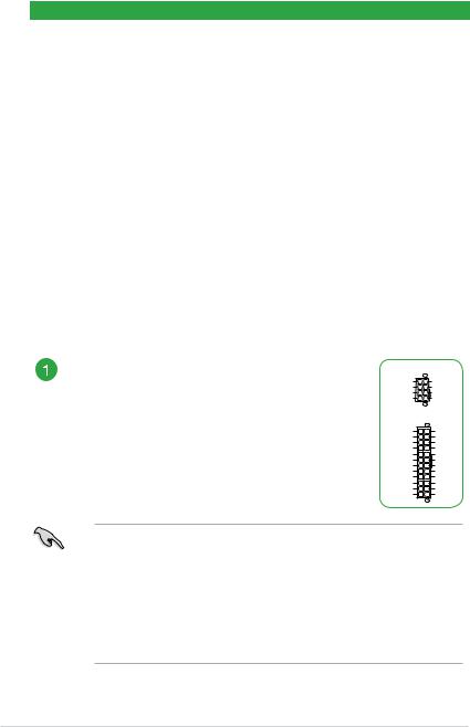
ATX power connectors (24-pin EATXPWR, 8-pin EATX12V)
Correctly orient the ATX power supply plugs into these connectors and push down firmly until the connectors completely fit.
EATX12V
|
GND |
+12V DC |
|
GND |
+12V DC |
|
GND |
+12V DC |
|
GND |
+12V DC |
|
PIN 1 |
|
|
EATXPWR |
|
+3 Volts |
GND |
|
+12 |
Volts |
+5 Volts |
+12 |
Volts |
+5 Volts |
+5V Standby |
+5 Volts |
|
Power OK |
-5 Volts |
|
|
GND |
GND |
+5 Volts |
GND |
|
|
GND |
GND |
+5 Volts |
PSON# |
|
|
GND |
GND |
+3 |
Volts |
-12 Volts |
+3 |
Volts |
+3 Volts |
|
PIN 1 |
|
•The 8-pin Power Plug LED lights up to indicate that the 8-pin power plug is not connected.
•For a fully configured system, we recommend that you use a power supply unit (PSU) that complies with ATX 12 V Specification 2.0 (or later version) and provides a minimum power of 350 W. This PSU type has 24-pin and 8-pin power plugs.
•We recommend that you use a PSU with higher power output when configuring a system with more power-consuming devices or when you intend to install additional devices. The system may become unstable or may not boot up if the power is inadequate.
1-2 |
Chapter 1: Product Introduction |
 Loading...