


ASUS P5G965PDF User Manual
V-Series P5G965
ASUS PC (Desktop Barebone)
E283 5
Firs t E diti o n V1
Sept e m b er 2 0 0 6
Copyright © 2006 ASUSTeK COMPUTER INC. All Rights Reserved.
No part of this manual, including the products and software described in it, may be reproduced,
transmitted, transcribed, stored in a retrieval system, or translated into any language in any form
or by any means, except documentation kept by the purchaser for backup purposes, without the
express written permission of ASUSTeK COMPUTER INC. (“ASUS”).
Product warranty or service will not be extended if: (1) the product is repaired, modied or
altered, unless such repair, modication of alteration is authorized in writing by ASUS; or (2) the
serial number of the product is defaced or missing.
ASUS PROVIDES THIS MANUAL “AS IS” WITHOUT WARRANTY OF ANY KIND, EITHER EXPRESS
OR IMPLIED, INCLUDING BUT NOT LIMITED TO THE IMPLIED WARRANTIES OR CONDITIONS OF
MERCHANTABILITY OR FITNESS FOR A PARTICULAR PURPOSE. IN NO EVENT SHALL ASUS,
ITS DIRECTORS, OFFICERS, EMPLOYEES OR AGENTS BE LIABLE FOR ANY INDIRECT, SPECIAL,
INCIDENTAL, OR CONSEQUENTIAL DAMAGES (INCLUDING DAMAGES FOR LOSS OF PROFITS, LOSS
OF BUSINESS, LOSS OF USE OR DATA, INTERRUPTION OF BUSINESS AND THE LIKE), EVEN IF ASUS
HAS BEEN ADVISED OF THE POSSIBILITY OF SUCH DAMAGES ARISING FROM ANY DEFECT OR
ERROR IN THIS MANUAL OR PRODUCT.
SPECIFICATIONS AND INFORMATION CONTAINED IN THIS MANUAL ARE FURNISHED FOR
INFORMATIONAL USE ONLY, AND ARE SUBJECT TO CHANGE AT ANY TIME WITHOUT NOTICE, AND
SHOULD NOT BE CONSTRUED AS A COMMITMENT BY ASUS. ASUS ASSUMES NO RESPONSIBILITY
OR LIABILITY FOR ANY ERRORS OR INACCURACIES THAT MAY APPEAR IN THIS MANUAL,
INCLUDING THE PRODUCTS AND SOFTWARE DESCRIBED IN IT.
Products and corporate names appearing in this manual may or may not be registered
trademarks or copyrights of their respective companies, and are used only for identication or
explanation and to the owners’ benet, without intent to infringe.
ii
Table of contents
Notices ................................................................................................ vi
Safety information ..............................................................................vii
About this guide .................................................................................viii
System package contents .................................................................... x
Cha p te r 1 : S y ste m I n tro d uc t ion
1.1 Welcome! .............................................................................. 1-2
1.2 Front panel ..........................................................................
1.3 Rear panel .............................................................................
1.4 Internal components .............................................................
Cha p te r 2 : Bas i c I nst a ll a tio n
2.1 Preparation ........................................................................... 2-2
2.2 Before you proceed ..............................................................
2.3 Removing the side cover and front panel assembly .............
2.4 Central Processing Unit .........................................................
2.4.1 Overview .................................................................
2.4.2 Installing CPU ..........................................................
2.4.3 Reinstalling the CPU fan and heatsink assembly .....
2.5 Installing a DIMM ...................................................................
2.5.1 Memory congurations ...........................................
2.5.2 Installing a DDR2 DIMM .........................................
2.5.3 Removing a DDR2 DIMM ........................................
2.6 Expansion slots ...................................................................
2.6.1 Installing an expansion card ..................................
2.6.2 Conguring an expansion card ..............................
2.6.3 PCI Express x 4 slot ..............................................
2.6.4 PCI slots ................................................................
2.6.5 PCI Express x 16 slot ............................................
2.7 Installing an optical drive ....................................................
2.8 Installing a hard disk drive ..................................................
2.9 Installing a oppy disk drive
2.10 Re-connecting cables ..........................................................
2.11 Removing the bay covers and reinstalling
the front panel assembly and side cover ............................
................................................ 2-20
1-2
1-3
1-6
2-2
2-3
2-4
2-4
2-4
2-6
2-8
2-8
2-12
2-12
2-13
2-13
2-13
2-15
2-15
2-15
2-16
2-17
2-21
2-22
iii
Table of contents
Cha p te r 3 : Sta r ti n g u p
3.1 Installing an operating system .............................................. 3-2
3.2 Powering up ..........................................................................
3.3 Support CD information ........................................................
3.3.1 Running the support CD ..........................................
3.3.2 Drivers menu ...........................................................
3.3.3 Utilities Disk ............................................................
3.3.4 Make Disk menu ......................................................
3.3.5 Manuals menu .........................................................
3.3.6 ASUS Contact information ......................................
3.4 Software information ............................................................
3.4.1 SoundMAX® High Denition Audio utility ...............
3.4.2 ASUS AI Gear ..........................................................
3.4.3 ASUS AI Nap ..........................................................
Cha p te r 4 : Mot h er b oar d I n for m at i on
4.1 Introduction .......................................................................... 4-2
4.2 Motherboard layout ..............................................................
4.3 Jumpers ................................................................................
4.4 Connectors ...........................................................................
3-10
3-2
3-3
3-3
3-4
3-5
3-6
3-7
3-7
3-8
3-8
3-9
4-2
4-3
4-5
Cha p te r 5 : BIO S S e tup
5.1 Managing and updating your BIOS ........................................ 5-2
5.1.1 Creating a bootable oppy disk ..............................
5.1.2 ASUS EZ Flash utility ...............................................
5.1.3 AFUDOS utility ........................................................
5.1.4 ASUS CrashFree BIOS 3 utility ................................
5.1.5 ASUS Update utility ................................................
5.2 BIOS setup program ............................................................
5.2.1 BIOS menu screen .................................................
5.2.2 Menu bar ...............................................................
5.2.3 Navigation keys .....................................................
5.2.4 Menu items ...........................................................
5.2.5 Sub-menu items ....................................................
5.2.6 Conguration elds ...............................................
iv
5-2
5-3
5-4
5-6
5-8
5-11
5-12
5-12
5-12
5-13
5-13
5-13

Table of contents
5.2.7 Pop-up window ...................................................... 5-13
5.2.8 Scroll bar ...............................................................
5.2.9 General help ..........................................................
5.3 Main menu ...........................................................................
5.3.1 System Time ........................................................
5.3.2 System Date ........................................................
5.3.3 Legacy Diskette A ...............................................
5.3.4 SATA1, SATA2, SATA3, and SATA4 ....................
5.3.5 IDE Conguation ....................................................
5.3.6 System Information
5.4 Advanced menu ..................................................................
5.4.1 JumperFree Conguration .....................................
5.4.2 USB conguration .................................................
5.4.3 CPU Conguration .................................................
5.4.4 Chipset ..................................................................
5.4.5 Onboard Devices Conguration .............................
5.4.6 PCI PnP ..................................................................
5.5 Power menu ........................................................................
5.5.1 Suspend Mode ......................................................
5.5.2 Repost Video on S3 Resume .................................
5.5.3 ACPI 2.0 Support ..................................................
5.5.4 ACPI APIC Support ................................................
5.5.5 APM Conguration ................................................
5.5.6 Hardware monitor .................................................
5.6 Boot menu ..........................................................................
5.6.1 Boot Device Priority ..............................................
5.6.2 Boot Settings Conguration .................................
5.6.3 Security .................................................................
5.7 Tools menu .........................................................................
5.7.1 ASUS EZ Flash 2 ....................................................
5.8 Exit menu ............................................................................
............................................... 5-17
5-13
5-13
5-14
5-14
5-14
5-14
5-15
5-16
5-18
5-18
5-20
5-21
5-22
5-24
5-26
5-27
5-27
5-27
5-27
5-27
5-28
5-29
5-30
5-30
5-31
5-32
5-34
5-34
5-35
v
Notices
Fed er al Co mm un ica ti on s C om mi ssi on S tat em en t
This device complies with Part 15 of the FCC Rules. Operation is subject to
the following two conditions:
•
This device may not cause harmful interference, and
•
This device must accept any interference received including
interference that may cause undesired operation.
This equipment has been tested and found to comply with the limits for a
Class B digital device, pursuant to Part 15 of the FCC Rules. These limits
are designed to provide reasonable protection against harmful interference
in a residential installation. This equipment generates, uses and can radiate
radio frequency energy and, if not installed and used in accordance with
manufacturer’s instructions, may cause harmful interference to radio
communications. However, there is no guarantee that interference will
not occur in a particular installation. If this equipment does cause harmful
interference to radio or television reception, which can be determined by
turning the equipment off and on, the user is encouraged to try to correct
the interference by one or more of the following measures:
•
Reorient or relocate the receiving antenna.
•
Increase the separation between the equipment and receiver.
•
Connect the equipment to an outlet on a circuit different from that to
which the receiver is connected.
•
Consult the dealer or an experienced radio/TV technician for help.
WARNING! The use of shielded cables for connection of the monitor to
the graphics card is required to assure compliance with FCC regulations.
Changes or modications to this unit not expressly approved by the
party responsible for compliance could void the user’s authority to
operate this equipment.
Can ad ia n D ep ar tme nt o f C om mu nic at io ns St at eme nt
This digital apparatus does not exceed the Class B limits for radio noise
emissions from digital apparatus set out in the Radio Interference
Regulations of the Canadian Department of Communications.
This class B digital apparatus complies with Canadian ICES-003.
vi
Safety information
Ele ct ri cal s af ety
•
To prevent electrical shock hazard, disconnect the power cable from
the electrical outlet before relocating the system.
•
When adding or removing devices to or from the system, ensure that
the power cables for the devices are unplugged before the signal cables
are connected.
•
If the power supply is broken, do not try to fix it by yourself. Contact a
qualified service technician or your retailer.
Ope ra ti on sa fe ty
•
Before installing devices into the system, carefully read all the
documentation that came with the package.
•
Before using the product, make sure all cables are correctly connected
and the power cables are not damaged. If you detect any damage,
contact your dealer immediately.
•
To avoid short circuits, keep paper clips, screws, and staples away from
connectors, slots, sockets and circuitry.
•
Avoid dust, humidity, and temperature extremes. Do not place the
product in any area where it may become wet. Place the product on a
stable surface.
•
If you encounter technical problems with the product, contact a
qualified service technician or your retailer.
Lithium-Ion Battery Warning
CAUTION: Danger of explosion if battery is incorrectly replaced.
Replace only with the same or equivalent type recommended by
the manufacturer. Dispose of used batteries according to the
manufacturer’s instructions.
VORSICHT: Explosionsgetahr bei unsachgemäßen Austausch der
Batterie. Ersatz nur durch denselben oder einem vom Hersteller
empfohlenem ähnljchen Typ. Entsorgung gebrauchter Batterien nach
Angaben des Herstellers.
LASER PRODUCT WARNING
CLA SS 1 LA SE R PRO DU CT
vii
About this guide
Aud ie nc e
This guide provides general information and installation instructions about
the ASUS V-Series P5G965 barebone system. This guide is intended for
experienced users and integrators with hardware knowledge of personal
computers.
How t hi s g ui de is o rg ani ze d
This guide contains the following parts:
1. Chap t e r 1: S y s tem i n t rodu c t i on
This chapter gives a general description of the ASUS V-Series P5G965
barebone system. The chapter lists the system features, including
introduction on the front and rear panel, and internal components.
2. Chap t e r 2: B a s ic i n s t alla t i o n
This chapter provides step-by-step instructions on how to install
components in the system.
3. Chap t e r 3: S t a rtin g u p
This chapter helps you power up the system and install drivers and
utilities from the support CD.
4. Chap t e r 4: M o t herb o a r d in f o r mati o n
This chapter gives information about the motherboard that comes
with the system. This chapter includes the motherboard layout,
jumper settings, and connector locations.
5. Chap t e r 5: B I O S se t u p
This chapter tells how to change system settings through the BIOS
Setup menus and describes the BIOS parameters.
viii
Con ve nt ion s us ed in t his g ui de
WARNING: Information to prevent injury to yourself when trying
to complete a task.
CAUTION: Information to prevent damage to the components
when trying to complete a task.
IMPORTANT: Instructions that you MUST follow to complete a
task.
NOTE: Tips and additional information to aid in completing a
task.
Whe re t o f in d mor e in for ma ti on
Refer to the following sources for additional information and for product
and software updates.
1. ASUS W e bsit e s
The ASUS websites worldwide provide updated information on
ASUS hardware and software products. Refer to the ASUS contact
information.
2. Opti o n a l Do c u m enta t i o n
Your product package may include optional documentation, such as
warranty yers, that may have been added by your dealer. These
documents are not part of the standard package.
ix
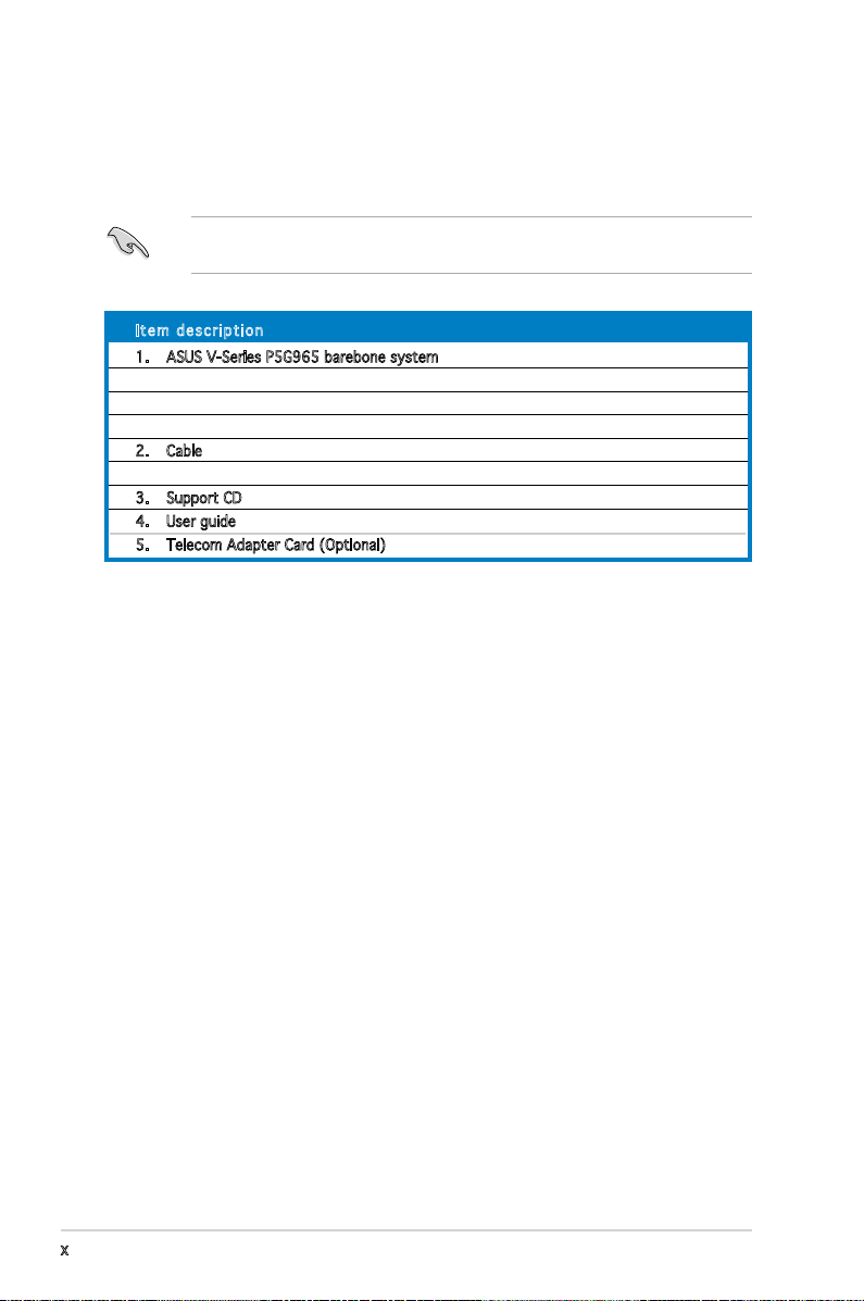
System package contents
Check your ASUS V-Series P5G965 barebone system package for the
following items.
If any of the items is damaged or missing, contact your retailer
immediately.
Ite m d escri p t i on
1. ASUS V-Series P5G965 barebone system with
• ASUS motherboard
• 250 W PFC power supply unit
• ASUS chassis
2. Cable
• AC power cable
3. Support CD
4. User guide
5. Telecom Adapter Card (Optional)
x
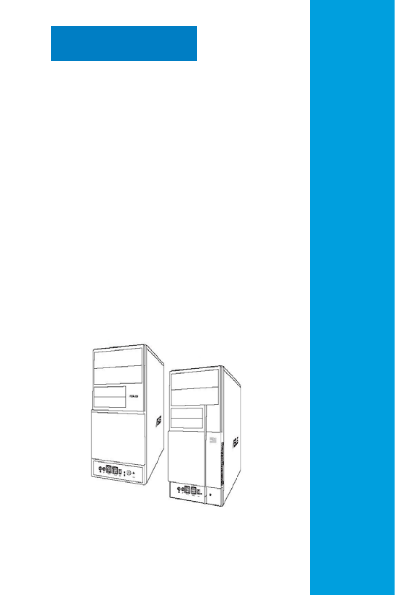
Chapter 1
This chapter gives a general
description of the ASUS
V-Series P5G965 Barebone
System. The chapter lists the
system features including
introduction on the front and rear
panel, and internal components.
System introduction
1.1 Welcome!
Thank you for choosing the ASUS V-Series P5G965!
The ASUS V-Series P5G965 is an all-in-one barebone system with a
versatile home entertainment feature.
The system comes in a stylish mini-tower casing and powered by the ASUS
motherboard that supports the Intel® Pentium® D, Intel® Pentium® 4 or
Intel® Celeron® processor in the 775-land package.
The system supports up to 4 GB of system memory using DDR2533/667/800 DIMMs. ATI integrated graphics, Serial ATA, USB 2.0, and
8-channel audio feature the system and take you ahead in the world of
power computing.
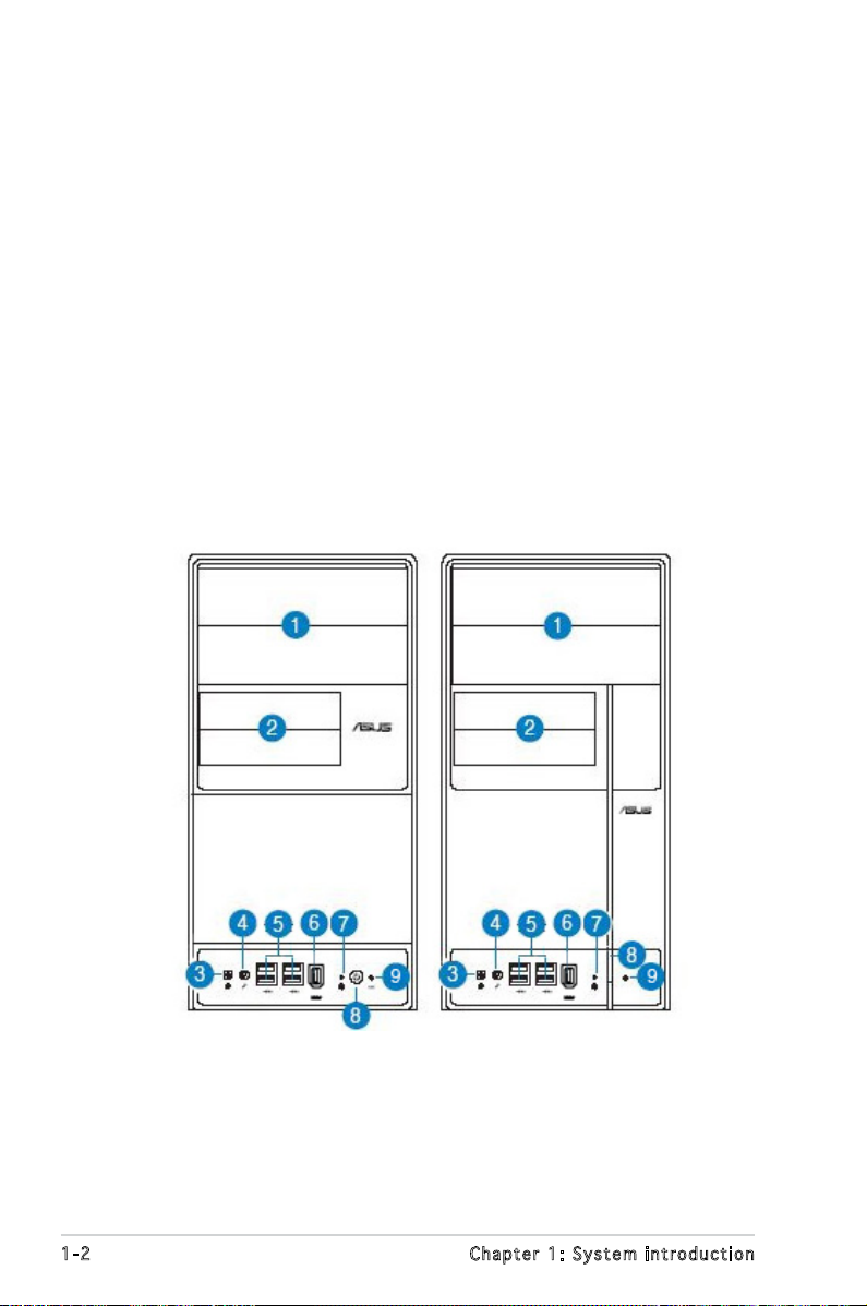
1.2 Front panel
The front panel includes the optical drive bays, oppy disk drive slot, power
button, and several I/O ports are located at the front panel.
1-2 Chapter 1: System introduction
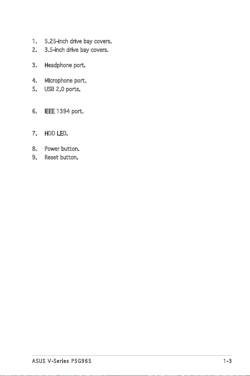
1. 5.25-inch drive bay covers. These bays are for IDE optical drives.
2. 3.5-inch drive bay covers. These slots are for 3.5-inch oppy or hard
disk drives.
3. Headphone port. This Line In (green) port connects a headphone with
a stereo mini-plug.
4. Microphone port. This Mic (pink) port connects a microphone.
5. USB 2.0 ports. These Universal Serial Bus 2.0 (USB 2.0) ports are
available for connecting USB 2.0 devices such as a mouse, printer,
scanner, camera, PDA, and others.
6. IEEE 1394 port. This 6-pin IEEE 1394 port provides high-speed
connectivity for audio/video devices, storage peripherals, PCs, or
portable devices.
7. HDD LED. This LED lights up when data is read from or written to the
hard disk drive.
8. Power button. Press this button to turn the system on.
9. Reset button. Press this button to reboot the system without turning
off the power.
1-3ASUS V-Series P5G965
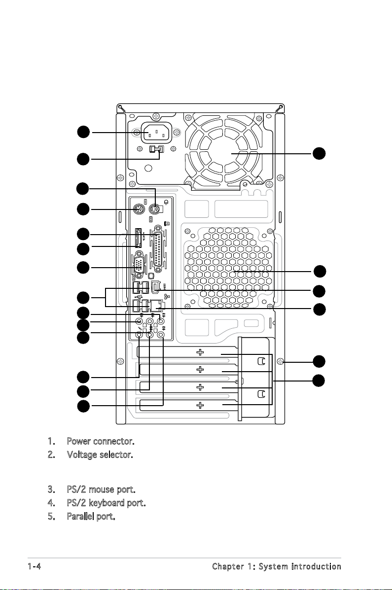
1.3 Rear panel
REAR
S P K
LINE
IN
FRONT
MIC IN
SIDE
S P K
C T R
BASS
The system rear panel includes the power connector and several I/O ports
that allow convenient connection of devices.
1
10
11
12
13
14
2
15
3
4
5
6
7
8
9
16
17
18
19
20
1. Power connector. This connector is for the power cable and plug.
2. Voltage selector. This switch allows you to adjust the system input
voltage according to the voltage supply in your area. See the section
“Voltage selector” on page 1-6 before adjusting this switch.
3. PS/2 mouse port. This port is for a PS/2 mouse.
4. PS/2 keyboard port. This port is for a PS/2 keyboard.
5. Parallel port. This 25-pin port connects a parallel printer, a scanner, or
other devices.
1-4 Chapter 1: System introduction
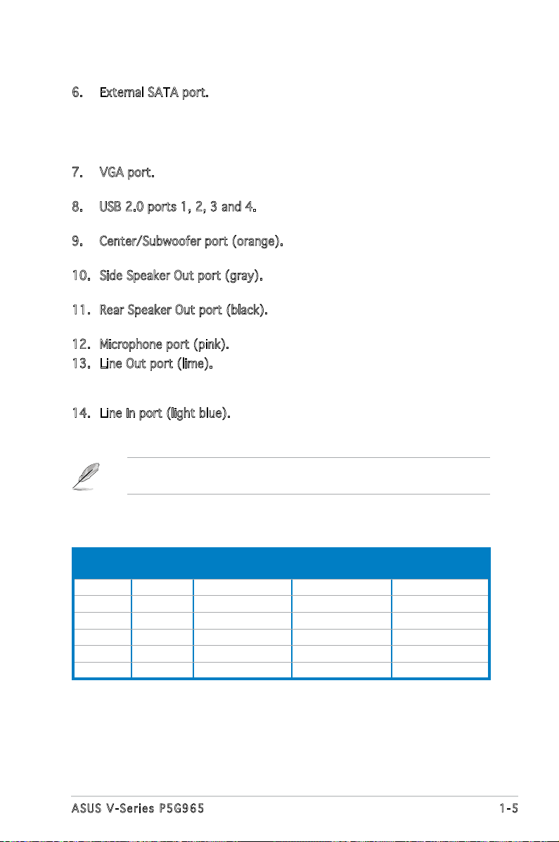
6. External SATA port. This port connects to an external SATA box or
a Serial ATA port multiplier. This port supports a Serial ATA hard
disk drive that you can combine with an external Serial ATA 3.0
Gb/s device to congure a RAID 0, RAID 1, or JBOD set through the
onboard JMicron SATA RAID controller.
7. VGA port. This port is for a VGA monitor or other VGA-compatible
devices.
8. USB 2.0 ports 1, 2, 3 and 4. These 4-pin Universal Serial Bus (USB)
ports are available for connecting USB 2.0 devices.
9. Center/Subwoofer port (orange). This port connects the center/
subwoofer speakers.
10. Side Speaker Out port (gray). This port connects the side speakers in
an 8-channel audio conguration.
11. Rear Speaker Out port (black). This port connects the rear speakers in
a 4-channel, 6-channel, or 8-channel audio conguration.
12. Microphone port (pink). This port connects a microphone.
13. Line Out port (lime). This port connects a headphone or a speaker.
In 4-channel and 6-channel conguration, the function of this port
becomes Front Speaker Out.
14. Line In port (light blue). This port connects the tape, CD, DVD player,
or other audio sources.
Refer to the audio conguration table below for the function of the audio
ports in 2, 4, 6, or 8-channel conguration.
Audio 2, 4, 6, or 8-channel conguration
Port Headset
2-channel
Light Blue Line In Line In Line In Line In
Lime Line Out Front Speaker Out Front Speaker Out Front Speaker Out
Pink Mic In Mic In Mic In Mic In
Orange – – Center/Subwoofer Center/Subwoofer
Black – Rear Speaker Out Rear Speaker Out Rear Speaker Out
Gray – – – Side Speaker Out
4-channel 6-channel 8-channel
1-5ASUS V-Series P5G965
15. Power supply unit fan vent. This vent is for the PSU fan that provides
ventilation inside the power supply unit.
16. Chassis fan vent. This vent is for the fan that provides ventilation
inside the system chassis.
17. IEEE 1394 port. This 6-pin IEEE 1394 port provides high-speed
connectivity for audio/video devices, storage peripherals, PCs, or
portable devices.
18. LAN (RJ-45) port. Supported by Realtek® Gigabit LAN controller,
this port allows Gigabit connection to a Local Area Network (LAN)
through a network hub. Refer to the table below for the LAN port LED
indications.
19. Cover screw. Remove the cover screws on the rear panel when
installing expansion cards.
20. Expansion slot metal brackets. Remove these brackets when installing
expansion cards.
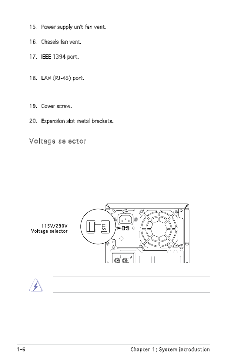
Vol ta ge se le ct or
The system’s power supply unit has a 115 V/230 V voltage selector
switch located beside the power connector. Use this switch to select the
appropriate system input voltage according to the voltage supply in your
area.
If the voltage supply in your area is 100-127 V, set this switch to 115 V.
If the voltage supply in your area is 200-240 V, set this switch to 230 V.
115 V / 2 30V
Vol t a g e sel e c t or
Setting the switch to 115V in a 230V environment or 230V in a 115V
environment will seriously damage the system!
1-6 Chapter 1: System introduction
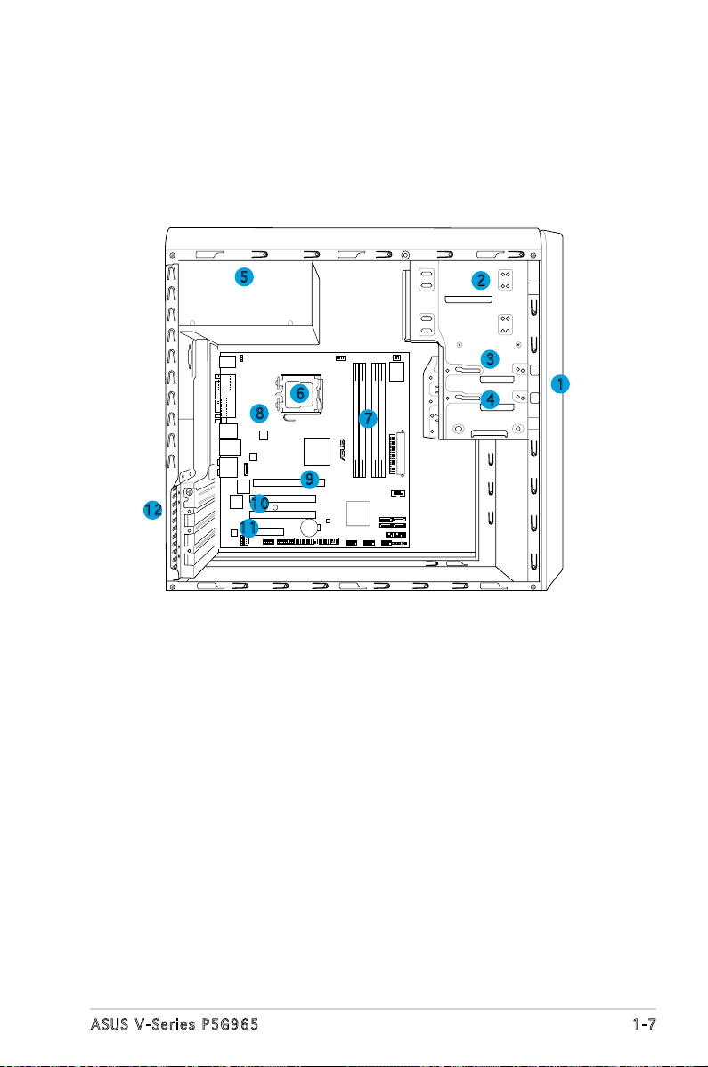
1.4 Internal components
24.5cm (9.6in)
24.5cm (9.6in
)
LGA775
PCIEX16
PCI1
PCI2
PCIEX4_1
EATXPWR
CD
CHA_FAN1
KBPWR
CPU_FAN
Super I/O
DDR2 DIMM_A1 (64 bit,240-pin module)
DDR2 DIMM_A2 (64 bit,240-pin module)
DDR2 DIMM_B1 (64 bit,240-pin module)
DDR2 DIMM_B2 (64 bit,240-pin module)
Intel G965MCH
Intel ICH8
FLOPPY
COM1
SATA1
SATA_RAID1
SATA2
SATA3
SATA4
PANEL
CHASSIS
CLRTC
USB910USB78USB56
PRI_EIDE
ADH
IE1394_2
AAFP
AD1988
RTL8111B
TSB43AB22A
JMicron
JMB363
8Mb BIOS
CR2032 3V
Lithium Cell
CMOS Power
AUDIO
LAN_USB34
1394_USB12
PARALLE PORT
PS/2KBMS
T: Mouse
B: Keyboard
ATX12V
R
P5B-VM
SB_PWR
ESATA
VGA
The illustration below is the internal view of the system when you remove
the top cover and the power supply unit. The installed components are
labeled for your reference. Proceed to Chapter 2 for instructions on
installing additional system components.
5
6
8
9
12
10
11
1. Front panel cover
2. 5.25-inch optical drive bays
3. Hard disk drive bay
4. Floppy disk drive bay
5. Power supply unit
6. CPU socket
2
3
1
4
7
7. DIMM sockets
8. ASUS motherboard
9. PCI Express x16 slot
10. PCI slots
11. PCI Express x4 slot
12. Metal bracket lock
1-7ASUS V-Series P5G965
1-8 Chapter 1: System introduction

Chapter 2
This chapter provides step-by-step
instructions on how to install
components in the system.
Basic installation
2.1 Preparation
R
P5B-VM
Onboard LED
SB_PWR
ON
Standby
Power
OFF
Powered
Off
Before you proceed, make sure that you have all the components you plan
to install in the system.
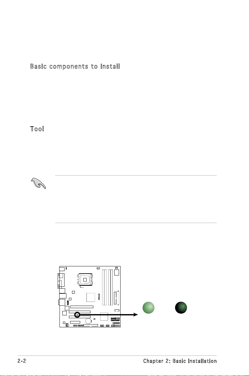
Bas i c c omp o ne n ts t o i nst a ll
1. Central Processing Unit (CPU)
2. DDR2 Dual Inline Memory Module (DIMM)
3. Expansion card(s)
4. Hard disk drive
5. Optical drive
6. Floppy disk drive
Too l
Phillips (cross) screw driver
2.2 Before you proceed
Take note of the following precautions before you install components into
the system.
•
Use a grounded wrist strap or touch a safely grounded object or
a metal object, such as the power supply case, before handling
components to avoid damaging them due to static electricity.
•
Hold components by the edges to avoid touching the ICs on them.
•
Whenever you uninstall any component, place it on a grounded
antistatic pad or in the bag that came with the component.
The motherboard comes with an onboard standby power LED. This LED
lights up to indicate that the system is ON, in sleep mode or in soft-off
mode, and not powered OFF. Unplug the power cable from the power outlet
and make sure that the standby power LED is OFF before installing any
system component.
2-2 Chapter 2: Basic installation
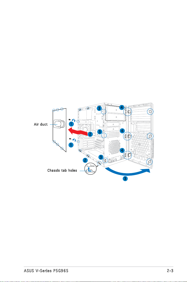
2.3 Removing the side cover and front
panel assembly
1. Remove the cover screws on the rear panel.
2. Pull the side cover toward the rear panel until its hooks disengage
from the chassis tab holes. Set the side cover aside.
3. Locate the front panel assembly hooks, then lift them until they
disengage from the chassis.
4. Swing the front panel assembly to the right, until the hinge-like tabs
on the right side of the assembly are exposed.
5. Remove the front panel assembly, then set aside.
Air d u ct
1
1
Cha s s i s tab h o les
3
3
2
2
3
4
4
4
3
2-3ASUS V-Series P5G965
2.4 Central Processing Unit (CPU)
2.4 .1 Ove rv ie w
The motherboard comes with a surface mount LGA775 socket designed
for the Intel® Core™2/Pentium® D/Pentium® 4/Pentium® Extreme and
Celeron® D processors.
• Your boxed Intel® Pentium® 4 LGA775 processor package should
come with installation instructions for the CPU, heatsink, and the
retention mechanism. If the instructions in this section do not match
the CPU documentation, follow the latter.
•
Check your motherboard to make sure that the PnP cap is on the
CPU socket and the socket contacts are not bent. Contact your
retailer immediately if the PnP cap is missing, or if you see any
damage to the PnP cap/socket contacts/motherboard components.
ASUS will shoulder the cost of repair only if the damage is shipment/
transit-related.
•
Keep the cap after installing the motherboard. ASUS will process
Return Merchandise Authorization (RMA) requests only if the
motherboard comes with the cap on the LGA775 socket.
• The product warranty does not cover damage to the socket
contacts resulting from incorrect CPU installation/removal, or
misplacement/loss/incorrect removal of the PnP cap.
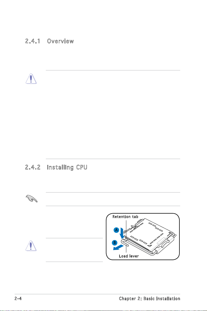
2.4 .2 Ins ta ll ing C PU
To install a CPU:
1. Locate the CPU socket on the motherboard.
Before installing the CPU, make sure that the socket box is facing
towards you and the load lever is on your left.
2. Press the load lever with your
Ret e n t ion t a b
thumb (A), then move it to the
left (B) until it is released from
the retention tab.
To prevent damage to the
socket pins, do not remove
the PnP cap unless you are
installing a CPU.
2-4 Chapter 2: Basic installation
A
B
Loa d l ever
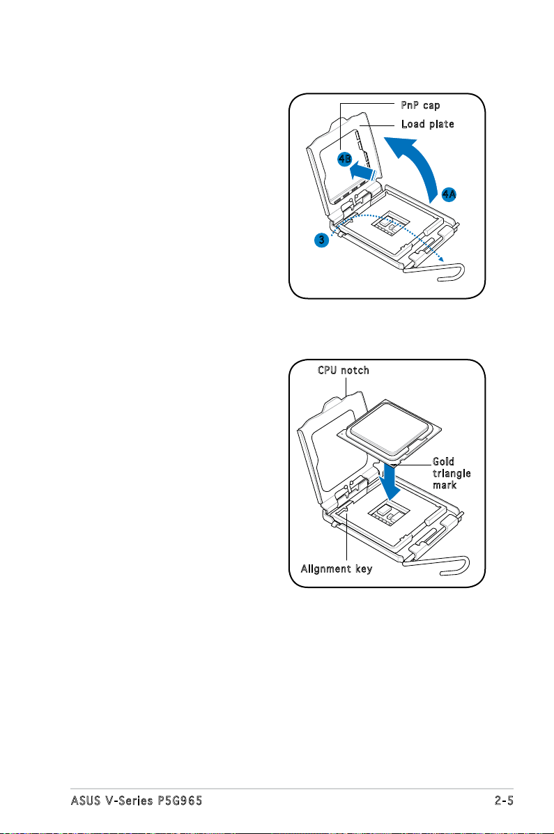
3. Lift the load lever in the
direction of the arrow to a 135º
angle.
PnP c a p
Loa d p late
4. Lift the load plate with your
thumb and forenger to a 100º
angle (4A), then push the PnP
cap from the load plate window
to remove (4B).
5. Position the CPU over the
socket, making sure that
the gold triangle is on the
bottom-left corner of the
socket. Fit the socket alignment
key into the CPU notch.
4B
4A
3
CPU n o tch
Gol d
tri a n g le
mar k
Ali g n m ent k e y
2-5ASUS V-Series P5G965
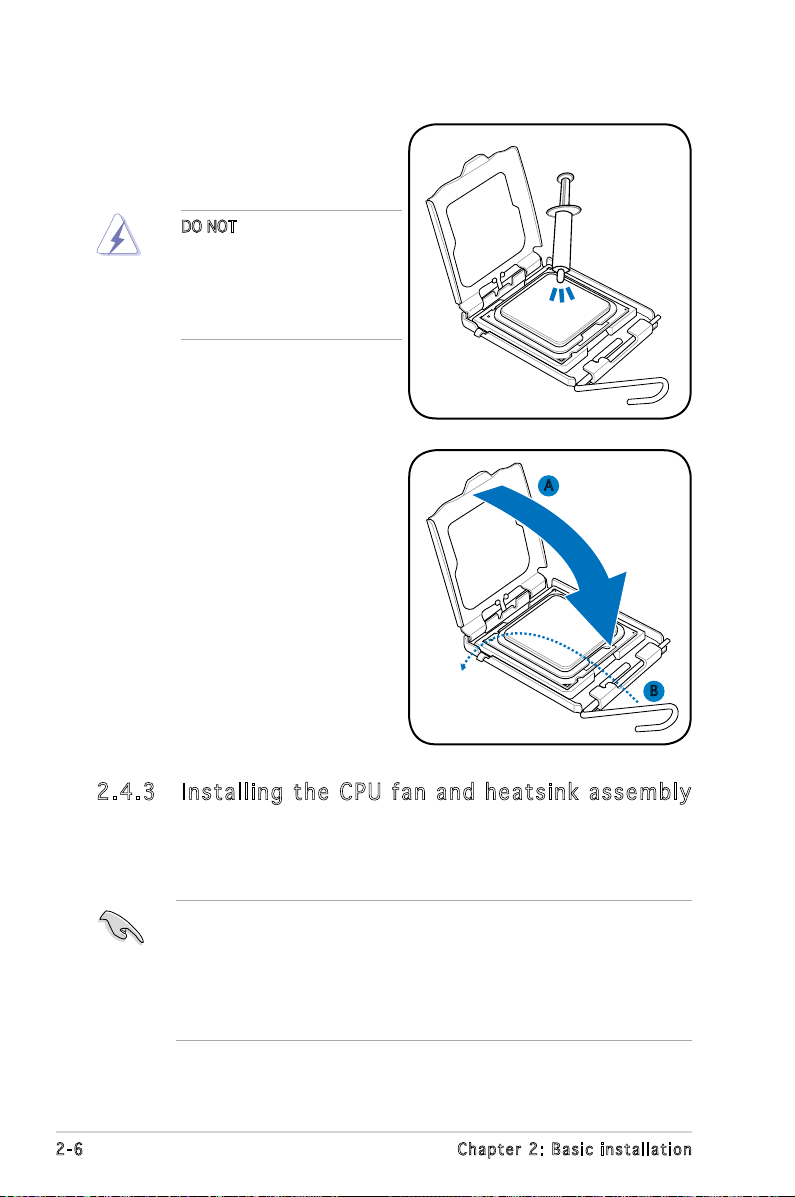
6. Apply Thermal Interface Material
on the CPU before closing the
load plate.
DO NOT eat the Thermal
Interface Material. If it gets
into your eyes or touches
your skin, make sure to wash
it off immediately, and seek
professional medical help.
7. Close the load plate (A), then
push the load lever (B) until it
snaps into the retention tab.
A
B
2.4 .3 Ins ta ll ing t he CP U f an a n d he a ts in k a ss em bly
The Intel® Pentium® 4 LGA775 processor requires a specially designed
heatsink and fan assembly to ensure optimum thermal condition and
performance.
• When you buy a boxed Intel® Pentium® 4 processor, the package
includes the CPU fan and heatsink assembly. If you buy a
CPU separately, make sure that you use only Intel®-certied
multi-directional heatsink and fan.
®
• Your Intel
a push-pin design and requires no tool to install.
2-6 Chapter 2: Basic installation
Pentium® 4 LGA775 heatsink and fan assembly comes in
If you purchased a separate CPU heatsink and fan assembly, make
R
P5B-VM
CPU Fan Connector
CPU_FAN
GND
CPU FAN PWR
CPU FAN IN
CPU FAN PWM
sure that the Thermal Interface Material is properly applied to the CPU
heatsink or CPU before you install the heatsink and fan assembly.
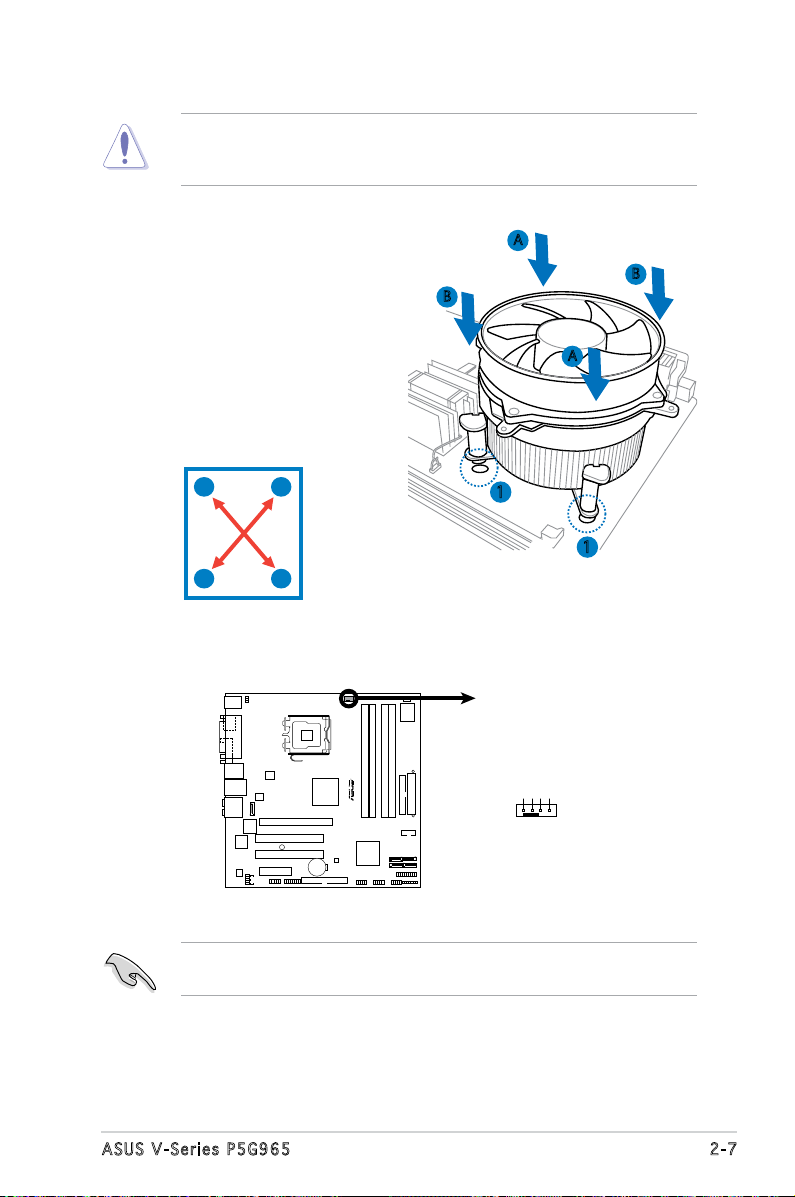
To install the CPU heatsink and fan:
1. Place the heatsink on top of the
installed CPU, making sure that
B
A
B
the four fasteners match the
holes on the motherboard.
A
2. Push down two fasteners at
a time in a diagonal sequence
to secure the heatsink and fan
assembly in place.
A
B
B
1
1
A
3. When the fan and heatsink assembly is in place, connect the CPU fan
cable to the connector on the motherboard.
Do not forget to connect the CPU fan connector! Hardware monitoring
errors can occur if you fail to plug this connector.
2-7ASUS V-Series P5G965
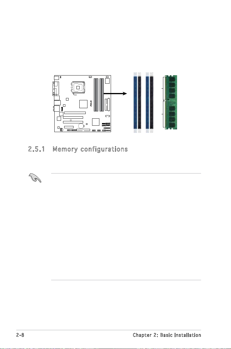
2.5 Installing a DIMM
R
P5B-VM
240-pin DDR2 DIMM Sockets
DIMM_A2
DIMM_B1
DIMM_B2
DIMM_A1
112 Pins128 Pins
The system motherboard comes with two Double Data Rate 2 (DDR2) Dual
Inline Memory Module (DIMM) sockets.
The following gure illustrates the location of the sockets:
2.5 .1 Mem or y con fi gu rat io ns
You may install 256 MB, 512 MB, 1 GB, and 2 GB unbuffered non-ECC DDR2
DIMMs into the DIMM sockets.
• You may install varying memory sizes in Channel A and Channel B.
The system maps the total size of the lower-sized channel for the
dual-channel conguration. Any excess memory from the highersized channel is then mapped for single-channel operation.
• Always install DIMMs with the same CAS latency. For optimum
compatibility, it is recommended that you obtain memory modules
from the same vendor.
• If you install four 1 or 2GB memory modules, the system may only
recognize less than 3GB because the address space is reserved for
other critical functions. This limitation appears on Windows® XP 32-bit
operation system which does not support Physical Address Extension
(PAE).
®
• If you install Windows
of less than 3GB is recommended.
• This motherboard does not support memory modules made up of
128 Mb chips or double sided x16 memory modules.
XP 32-bit operation system, a total memory
2-8 Chapter 2: Basic installation
Notes on memory limitations
• Due to chipset limitation, this motherboard can only support up to
8 GB on the operating systems listed below. You may install a
maximum of 2 GB DIMMs on each slot, but only DDR2-533 and
DDR2-667 2 GB density modules are available for this conguration.
32-bit 64-bit
Windows® 2000 Advanced Windows® XP Professional x64
Server Edition
• Some old-version DDR2-800/667 DIMMs may not match Intel®’s
On-Die-Termination (ODT) requirement and will automatically
downgrade to run at DDR2-533. If this happens, contact your
memory vendor to check the ODT value.
• Due to chipset limitation, DDR2-800 with CL=4 will be downgraded
to run at DDR2-667 by default setting. If you want to operate with
lower latency, adjust the memory timing manually.
• Due to chipset limitation, DDR2-667 with CL=3 will be downgraded
to run at DDR2-533 by default setting. If you want to operate with
lower latency, adjust the memory timing manually. There will be 8MB
reduction in total memory when enabling ASUS Thermostat function
under Single Channel mode, and 16MB reduction under Dual Channel
Mode.
• The total memory may has 8MB reduction under Single Channel
mode, and 16MB reduction under Dual Channel mode because the
address space is reserved for Intel® Quiet System Technology.
2-9ASUS V-Series P5G965
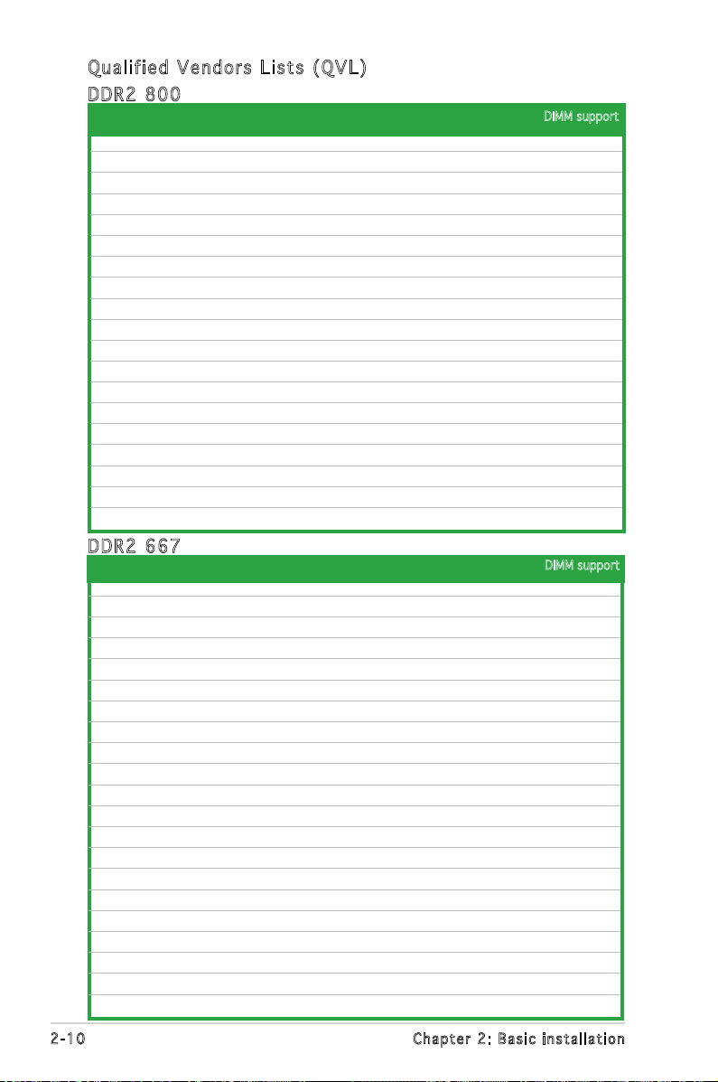
Qua l if i ed V en d ors Li s ts ( QV L )
DDR 2 80 0
Siz e Ve ndo r Chi p No. Side(s) Pa rt No . A B C
512MB KINGSTON K4T51083QC SS KVR800D2N5/512 • • •
1024MB KINGSTON K4T51083QC DS KVR800D2N5/1G • •
512MB Qimonda HYB18T256800AF25F DS HYS64T64020HU-25F-A • •
256MB Qimonda HYB18T512160BF-25F SS HYS64T32000HU-25F-B • •
512MB Qimonda HYB18T512800BF25F SS HYS64T64000HU-25F-B • •
1024MB Qimonda HYB18T512800BF25F DS HYS64T128020HU-25F-B • • •
512MB SAMSUNG EDD339XX SS M378T6553CZ3-CE7 • • •
256MB SAMSUNG K4T51163QC-ZCE7 SS M378T3354CZ3-CE7 • •
512MB Hynix HY5PS12821BFP-S5 SS HYMP564U64BP8-S5 • •
1024MB Hynix HY5PS12821BFP-S5 DS HYMP512U64BP8-S5 •
512MB MICRON 5JAIIZ9DQQ SS MT8HTF6464AY-80EA3 • •
1024MB MICRON 5JAIIZ9DQQ DS MT16HTF12864AY-80EA3 • •
512MB MICRON 5ZD22D9GKX SS MT8HTF6464AY-80ED4 •
1024MB MICRON 5ZD22D9GKX DS MT16HTF12864AY-80ED4 • •
512MB MICRON 6CD22D9GKX SS MT8HTF6464AY-80ED4 • •
1024MB MICRON 6CD22D9GKX DS MT16HTF12864AY-80ED4 •
1024MB CORSAIR Heat-Sink Package DS CM2X1024-6400C4 •
512MB Crucial Heat-Sink Package SS BL6464AA804.8FD • •
1024MB Crucial Heat-Sink Package DS BL12864AA804.16FD •
DDR 2 66 7
Siz e Ve ndo r Chi p No Side (s) Part No . A B C
512MB KINGSTON E5108AE-6E-E SS KVR667D2N5/512 • •
1024MB KINGSTON E5108AE-6E-E DS KVR667D2N5/1G • •
512MB KINGSTON E5108AE-6E-E SS KVR667D2E5/512 • •
256MB KINGSTON HYB18T256800AF3 SS KVR667D2N5/256 • •
256MB Qimonda HYB18T512160AF-3S SS HYS64T32000HU-3S-A • •
512MB Qimonda HYB18T512800AF3S SS HYS64T64000HU-3S-A • •
1024MB Qimonda HYB18T512800AF3S DS HYS64T128020HU-3S-A • •
256MB Qimonda HYB18T512160BF-3S SS HYS64T32000HU-3S-B • •
512MB Qimonda HYB18T512800BF3S SS HYS64T64000HU-3S-B • •
1024MB Qimonda HYB18T512800BF3S DS HYS64T128020HU-3S-B •
256MB SAMSUNG K4T51163QC-ZCE6 SS M378T3354CZ0-CE6 • •
512MB SAMSUNG ZCE6K4T51083QC SS M378T6553CZ0-CE6 •
1024MB SAMSUNG ZCE6K4T51083QC DS M378T2953CZ0-CE6 • •
512MB Hynix HY5PS12821AFP-Y5 SS HYMP564U64AP8-Y5 • • •
512MB Hynix HY5PS12821AFP-Y4 SS HYMP564U64AP8-Y4 • •
256MB ELPIDA E2508AB-6E-E SS EBE25UC8ABFA-6E-E • •
512MB ELPIDA E5108AE-6E-E SS EBE51UD8AEFA-6E-E • •
512MB A-DATA AD29608A8B-3EG SS M20AD5Q3H3163J1C52 • •
512MB Transcend E5108AE-6E-E SS TS64MLQ64V6J • •
1024MB Transcend E5108AE-6E-E DS TS128MLQ64V6J •
1024MB Transcend J12Q3AB-6 DS JM388Q643A-6 •
DIMM support
DIMM support
2-10 Chapter 2: Basic installation
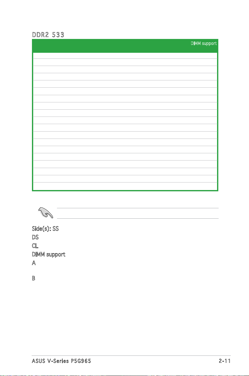
DDR 2 53 3
Siz e Ve ndo r Chi p No. Side(s) Pa rt No . A B C
256MB KINGSTON E5116AF-5C-E SS KVR533D2N4/256 • •
512MB KINGSTON HYB18T512800AF37 SS KVR533D2N4/512 • •
1024MB KINGSTON 5YDIID9GCT DS KVR533D2N4/1G • •
256MB Qimonda HYB18T512160AF-3.7 SS HYS64T32000HU-3.7-A • •
512MB Qimonda HYB18T512800AF37 SS HYS64T64000HU-3.7-A • •
1024MB Qimonda HYB18T512800AF37 DS HYS64T128020HU-3.7-A • •
256MB Qimonda HYB18T5121608BF-3.7 SS HYS64T32000HU-3.7-B • • •
512MB Qimonda HYB18T512800BF37 SS HYS64T64000HU-3.7-B • • •
1024MB Qimonda HYB18T512800BF37 DS HYS64T128020HU-3.7-B •
512MB Hynix HY5PS12821F-C4 SS HYMP564U648-C4 •
1024MB Hynix HY5PS12821F-C4 DS HYMP512U648-C4 • •
512MB Hynix HY5PS12821AFP-C3 SS HYMP564U64AP8-C3 • •
1024MB Hynix HY5PS12821AFP-C3 DS HYMP512U64AP8-C3 • •
512MB ELPIDA E5108AB-5C-E SS EBE51UD8ABFA-5C-E • •
256MB Apacer E5116AB-5C-E SS 78.81077.420 • •
512MB KINGMAX E5108AE-5C-E SS KLBC28F-A8EB4 • • •
1024MB KINGMAX E5108AE-5C-E DS KLBD48F-A8EB4 •
512MB KINGMAX KKEA88E4AAK-37 SS KLBC28F-A8KE4 •
1024MB KINGMAX 5MB22D9DCN DS KLBD48F-A8ME4 •
Visit the ASUS website (www.asus.com) for the latest QVL.
DIMM support
Side(s): SS - Single-sided
DS - Double-sided
CL: CAS Latency
DIMM support:
A -Supports one module inserted into either slot, in Single-channel memory
conguration.
B -Supports one pair of modules inserted into both slots as one pair of
Dual-channel memory conguration.
2-11ASUS V-Series P5G965
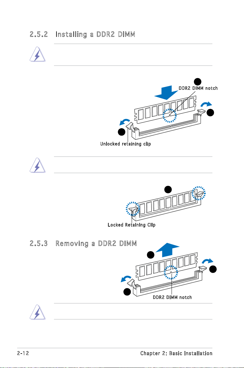
2.5 .2 Ins ta ll ing a D DR2 D IM M
Make sure to unplug the power supply before adding or removing DIMMs
or other system components. Failure to do so may cause severe damage
to both the motherboard and the components.
1. Unlock a DDR2 DIMM socket
by pressing the retaining clips
outward.
2. Align a DIMM on the socket
such that the notch on the
DIMM matches the break on
the socket.
Unl o c k ed re t a i ning c l i p
A DDR2 DIMM is keyed with a notch so that it ts in only one direction.
DO NOT force a DIMM into a socket to avoid damaging the DIMM.
1
2
DDR 2 D IMM n o t c h
1
3. Firmly insert the DIMM into the
3
socket until the retaining clips
snap back in place and the DIMM
is properly seated.
Loc k e d Reta i n i ng Cl i p
2.5 .3 Rem ov in g a D DR 2 D IM M
Follow these steps to remove a DIMM.
1. Simultaneously press the
retaining clips outward to
unlock the DIMM.
1
Support the DIMM lightly with your ngers when pressing the retaining
clips. The DIMM might get damaged when it ips out with extra force.
2. Remove the DIMM from the socket.
2-12 Chapter 2: Basic installation
2
DDR 2 D IMM n o t c h
1
 Loading...