

ASUS M4A78-E User Manual

M4A78-E
Motherboard

E4437
First Edition
January 2009
Copyright © 2009 ASUSTeK COMPUTER INC. All Rights Reserved.
No part of this manual, including the products and software described in it, may be reproduced,
transmitted, transcribed, stored in a retrieval system, or translated into any language in any form or by any
means, except documentation kept by the purchaser for backup purposes, without the express written
permission of ASUSTeK COMPUTER INC. (“ASUS”).
Product warranty or service will not be extended if: (1) the product is repaired, modied or altered, unless
such repair, modication of alteration is authorized in writing by ASUS; or (2) the serial number of the
product is defaced or missing.
ASUS PROVIDES THIS MANUAL “AS IS” WITHOUT WARRANTY OF ANY KIND, EITHER EXPRESS
OR IMPLIED, INCLUDING BUT NOT LIMITED TO THE IMPLIED WARRANTIES OR CONDITIONS OF
MERCHANTABILITY OR FITNESS FOR A PARTICULAR PURPOSE. IN NO EVENT SHALL ASUS, ITS
DIRECTORS, OFFICERS, EMPLOYEES OR AGENTS BE LIABLE FOR ANY INDIRECT, SPECIAL,
INCIDENTAL, OR CONSEQUENTIAL DAMAGES (INCLUDING DAMAGES FOR LOSS OF PROFITS,
LOSS OF BUSINESS, LOSS OF USE OR DATA, INTERRUPTION OF BUSINESS AND THE LIKE),
EVEN IF ASUS HAS BEEN ADVISED OF THE POSSIBILITY OF SUCH DAMAGES ARISING FROM ANY
DEFECT OR ERROR IN THIS MANUAL OR PRODUCT.
SPECIFICATIONS AND INFORMATION CONTAINED IN THIS MANUAL ARE FURNISHED FOR
INFORMATIONAL USE ONLY, AND ARE SUBJECT TO CHANGE AT ANY TIME WITHOUT NOTICE,
AND SHOULD NOT BE CONSTRUED AS A COMMITMENT BY ASUS. ASUS ASSUMES NO
RESPONSIBILITY OR LIABILITY FOR ANY ERRORS OR INACCURACIES THAT MAY APPEAR IN THIS
MANUAL, INCLUDING THE PRODUCTS AND SOFTWARE DESCRIBED IN IT.
Products and corporate names appearing in this manual may or may not be registered trademarks or
copyrights of their respective companies, and are used only for identication or explanation and to the
owners’ benet, without intent to infringe.
ii

Contents
Contents ...................................................................................................................... iii
Notices ......................................................................................................................vii
Safety information .................................................................................................... viii
About this guide ......................................................................................................... ix
M4A78-E specications summary ............................................................................ xi
Chapter 1: Product introduction
1.1 Welcome! ....................................................................................................1-1
1.2 Package contents.......................................................................................1-1
1.3 Special features..........................................................................................1-2
1.3.1 Product highlights........................................................................1-2
1.3.2 ASUS unique features.................................................................1-3
1.3.3 ASUS intelligent performance and overclocking features ........... 1-5
Chapter 2: Hardware information
2.1 Before you proceed ...................................................................................2-1
2.2 Motherboard overview ............................................................................... 2-2
2.2.1 Motherboard layout ..................................................................... 2-2
2.2.2 Layout contents ...........................................................................2-3
2.2.3 Placement direction.....................................................................2-4
2.2.4 Screw holes.................................................................................2-4
2.3 Central Processing Unit (CPU) .................................................................2-5
2.3.1 Installing the CPU .......................................................................2-5
2.3.2 Installing the CPU heatsink and fan ............................................ 2-7
2.4 System memory .......................................................................................2-10
2.4.1 Overview ................................................................................... 2-10
2.4.2 Memory congurations .............................................................. 2-11
2.4.3 Installing a DIMM ......................................................................2-16
2.4.4 Removing a DIMM ....................................................................2-16
2.5 Expansion slots........................................................................................2-17
2.5.1 Installing an expansion card......................................................2-17
2.5.2 Conguring an expansion card .................................................2-17
2.5.3 Interrupt assignments................................................................2-18
2.5.4 PCI slots ....................................................................................2-19
2.5.5 PCI Express x1 slots ................................................................. 2-19
2.5.6 Two PCI Express x16 slots .......................................................2-19
2.6 ASUS VGA switch card ............................................................................2-20
2.7 Jumpers ....................................................................................................2-21
2.8 Connectors ...............................................................................................2-23
iii

Contents
2.8.1 Rear panel connectors .............................................................. 2-23
2.8.2 Audio I/O connections ............................................................... 2-24
2.8.3 Internal connectors....................................................................2-27
2.9 Starting up for the rst time .................................................................... 2-38
2.10 Turning off the computer ......................................................................... 2-38
Chapter 3: BIOS setup
3.1 Knowing BIOS ............................................................................................3-1
3.2 Updating BIOS ............................................................................................ 3-1
3.2.1 ASUS Update utility.....................................................................3-2
3.2.2 Creating a bootable oppy disk ................................................... 3-4
3.2.3 ASUS EZ Flash 2 utility ............................................................... 3-5
3.2.4 ASUS CrashFree BIOS 3 utility...................................................3-6
3.3 BIOS setup program ..................................................................................3-7
3.3.1 BIOS menu screen ...................................................................... 3-7
3.3.2 Menu bar ..................................................................................... 3-7
3.3.3 Navigation keys ........................................................................... 3-8
3.3.4 Menu items..................................................................................3-8
3.3.5 Submenu items ........................................................................... 3-8
3.3.6 Conguration elds .....................................................................3-8
3.3.7 Pop-up window............................................................................3-8
3.3.8 Scroll bar ..................................................................................... 3-8
3.3.9 General help................................................................................3-8
3.4 Main menu ..................................................................................................3-9
3.4.1 Primary IDE Master/Slave; SATA 1–5; ESATA ............................ 3-9
3.4.2 Storage Conguration ............................................................... 3-11
3.4.3 System Information ................................................................... 3-12
3.5 Ai Tweaker menu ...................................................................................... 3-12
3.5.1 AI Overclocking Tuner ............................................................... 3-12
3.5.2 CPU Ratio ................................................................................. 3-13
3.5.3 CPU Bus Frequency .................................................................3-13
3.5.4 PCIE Frequency ........................................................................ 3-13
3.5.5 DRAM Frequency Control ........................................................ 3-13
3.5.6 CPU/NB Frequency ..................................................................3-13
3.5.7 HT Link Speed .........................................................................3-13
3.5.8 Memory Conguration ............................................................... 3-14
3.5.9 DRAM Timing Conguration......................................................3-15
3.5.10 CPU Voltage .............................................................................3-16
3.5.11 CPU/NB Voltage .......................................................................3-17
iv

Contents
3.5.12 CPU VDDA Voltage .................................................................. 3-17
3.5.13 DRAM Voltage ..........................................................................3-17
3.5.14 HT Voltage ...............................................................................3-17
3.5.15 NB Voltage ...............................................................................3-17
3.5.16 NB 1.8V Voltage ....................................................................... 3-17
3.5.17 SB Voltage ...............................................................................3-17
3.5.18 CPU Spread Spectrum..............................................................3-17
3.5.19 PCIE Spread Spectrum ............................................................. 3-17
3.6 Advanced menu .......................................................................................3-18
3.6.1 CPU Conguration .................................................................... 3-18
3.6.2 Chipset ...................................................................................... 3-19
3.6.3 Onboard Devices Conguration ................................................ 3-23
3.6.4 USB Conguration ....................................................................3-24
3.6.5 PCIPnP .....................................................................................3-25
3.7 Power menu .............................................................................................. 3-26
3.7.1 Suspend Mode ......................................................................... 3-26
3.7.2 ACPI 2.0 Support ...................................................................... 3-26
3.7.3 ACPI APIC Support ................................................................... 3-26
3.7.4 APM Conguration .................................................................... 3-27
3.7.5 Hardware Monitor......................................................................3-28
3.8 Boot menu ................................................................................................3-29
3.8.1 Boot Device Priority...................................................................3-29
3.8.2 Boot Settings Conguration ......................................................3-30
3.8.3 Security ..................................................................................... 3-31
3.9 Tools menu ............................................................................................... 3-33
3.9.1 ASUS EZ Flash 2 ...................................................................... 3-33
3.9.2 Express Gate ............................................................................3-34
3.9.3 ASUS O.C. Prole ..................................................................... 3-35
3.9.4 AI NET 2 .................................................................................... 3-36
3.10 Exit menu .................................................................................................. 3-37
Chapter 4: Software support
4.1 Installing an operating system .................................................................4-1
4.2 Support DVD information .......................................................................... 4-1
4.2.1 Running the support DVD ........................................................... 4-1
4.2.2 Obtaining the software manuals..................................................4-2
4.3 Software information .................................................................................4-3
4.3.1 Cool ‘n’ Quiet!™ Technology ....................................................... 4-3
4.3.2 Audio congurations....................................................................4-4
v

Contents
4.3.3 ASUS PC Probe II ....................................................................... 4-5
4.3.4 ASUS Express Gate SSD / ASUS Express Gate ........................ 4-6
4.3.5 ASUS AI Suite ............................................................................. 4-7
4.3.6 ASUS EPU .................................................................................. 4-8
4.3.7 ASUS Q-Fan 2 ............................................................................ 4-9
4.3.8 ASUS AI Nap.............................................................................4-10
4.3.9 ASUS TurboV ............................................................................ 4-11
4.3.10 ASUS Turbo Key ....................................................................... 4-12
4.4 RAID congurations ................................................................................4-13
4.4.1 RAID denitions ........................................................................4-13
4.4.2 Installing Serial ATA hard disks .................................................4-14
4.4.3 Setting the RAID item in BIOS .................................................. 4-14
4.4.4 AMD® Option ROM Utility® ........................................................ 4-15
4.5 Creating a RAID driver disk.....................................................................4-18
4.5.1 Creating a RAID driver disk without entering the OS ................ 4-18
4.5.2 Creating a RAID/SATA driver disk in Windows® ........................ 4-18
Chapter 5: ATI® CrossFireX™ technology support
5.1 ATI® CrossFireX™ technology ..................................................................5-1
5.1.1 Requirements .............................................................................. 5-1
5.1.2 Before you begin ......................................................................... 5-1
5.1.3 Installing CrossFireX™ graphics cards ....................................... 5-2
5.1.4 Installing the device drivers ......................................................... 5-3
5.1.5 Enabling the ATI® CrossFireX™ technology ...............................5-3
5.2 ATI® Hybrid CrossFireX™ .......................................................................... 5-5
5.2.1 System requirements .................................................................. 5-5
5.2.2 Before you proceed ..................................................................... 5-5
5.2.3 Installing AMD Chipset Driver .....................................................5-6
vi

Notices
Federal Communications Commission Statement
This device complies with Part 15 of the FCC Rules. Operation is subject to the following two
conditions:
•
This device may not cause harmful interference, and
•
This device must accept any interference received including interference that may cause
undesired operation.
This equipment has been tested and found to comply with the limits for a Class B digital
device, pursuant to Part 15 of the FCC Rules. These limits are designed to provide
reasonable protection against harmful interference in a residential installation. This
equipment generates, uses and can radiate radio frequency energy and, if not installed
and used in accordance with manufacturer’s instructions, may cause harmful interference
to radio communications. However, there is no guarantee that interference will not occur
in a particular installation. If this equipment does cause harmful interference to radio or
television reception, which can be determined by turning the equipment off and on, the user
is encouraged to try to correct the interference by one or more of the following measures:
•
Reorient or relocate the receiving antenna.
•
Increase the separation between the equipment and receiver.
•
Connect the equipment to an outlet on a circuit different from that to which the receiver is
connected.
•
Consult the dealer or an experienced radio/TV technician for help.
The use of shielded cables for connection of the monitor to the graphics card is required
to assure compliance with FCC regulations. Changes or modications to this unit not
expressly approved by the party responsible for compliance could void the user’s authority
to operate this equipment.
Canadian Department of Communications Statement
This digital apparatus does not exceed the Class B limits for radio noise emissions from
digital apparatus set out in the Radio Interference Regulations of the Canadian Department
of Communications.
This class B digital apparatus complies with Canadian ICES-003.
vii
Safety information
Electrical safety
• To prevent electrical shock hazard, disconnect the power cable from the electrical outlet
before relocating the system.
• When adding or removing devices to or from the system, ensure that the power cables
for the devices are unplugged before the signal cables are connected. If possible,
disconnect all power cables from the existing system before you add a device.
• Before connecting or removing signal cables from the motherboard, ensure that all
power cables are unplugged.
• Seek professional assistance before using an adapter or extension cord. These devices
could interrupt the grounding circuit.
• Make sure that your power supply is set to the correct voltage in your area. If you are
not sure about the voltage of the electrical outlet you are using, contact your local power
company.
• If the power supply is broken, do not try to x it by yourself. Contact a qualied service
technician or your retailer.
Operation safety
• Before installing the motherboard and adding devices on it, carefully read all the manuals
that came with the package.
• Before using the product, make sure all cables are correctly connected and the power
cables are not damaged. If you detect any damage, contact your dealer immediately.
• To avoid short circuits, keep paper clips, screws, and staples away from connectors,
slots, sockets and circuitry.
• Avoid dust, humidity, and temperature extremes. Do not place the product in any area
where it may become wet.
• Place the product on a stable surface.
• If you encounter technical problems with the product, contact a qualied service
technician or your retailer.
viii
DO NOT throw the motherboard in municipal waste. This product has been designed to
enable proper reuse of parts and recycling. This symbol of the crossed out wheeled bin
indicates that the product (electrical and electronic equipment) should not be placed in
municipal waste. Check local regulations for disposal of electronic products.
DO NOT throw the mercury-containing button cell battery in municipal waste. This symbol
of the crossed out wheeled bin indicates that the battery should not be placed in municipal
waste.

About this guide
This user guide contains the information you need when installing and conguring the
motherboard.
How this guide is organized
This guide contains the following parts:
• Chapter 1: Product introduction
This chapter describes the features of the motherboard and the new technology it
supports.
• Chapter 2: Hardware information
This chapter lists the hardware setup procedures that you have to perform when
installing system components. It includes description of the switches, jumpers, and
connectors on the motherboard.
• Chapter 3: BIOS setup
This chapter tells how to change system settings through the BIOS Setup menus.
Detailed descriptions of the BIOS parameters are also provided.
• Chapter 4: Software support
This chapter describes the contents of the support DVD that comes with the
motherboard package and the software.
• Chapter 5: ATI® CrossFireX™ support
This chapter describes the ATI® CrossFireX™ feature and shows the graphics card
installation procedures.
Where to nd more information
Refer to the following sources for additional information and for product and software
updates.
1. ASUS websites
The ASUS website provides updated information on ASUS hardware and software
products. Refer to the ASUS contact information.
2. Optional documentation
Your product package may include optional documentation, such as warranty yers,
that may have been added by your dealer. These documents are not part of the
standard package.
ix
Conventions used in this guide
To make sure that you perform certain tasks properly, take note of the following symbols used
throughout this manual.
DANGER/WARNING: Information to prevent injury to yourself when trying to
complete a task.
CAUTION: Information to prevent damage to the components when trying to
complete a task.
IMPORTANT: Instructions that you MUST follow to complete a task.
NOTE: Tips and additional information to help you complete a task.
Typography
Bold text Indicates a menu or an item to select.
Italic
s Used to emphasize a word or a phrase.
<Key> Keys enclosed in the less-than and greater-than sign means
that you must press the enclosed key.that you must press the enclosed key.
Example: <Enter> means that you must press the Enter or
Return key.Return key.
<Key1> + <Key2> + <Key3> If you must press two or more keys simultaneously, the key
names are linked with a plus sign (+).
Example: <Ctrl> + <Alt> + <Del>
Command Means that you must type the command exactly as shown, then
supply the required item or value enclosed in brackets.
Example: At the DOS prompt, type the command line:
afudos /iM4A78E.ROM
x

M4A78-E specications summary
CPU Phenom™ X4 / Phenom™ X3 / Athlon™ X2 / Athlon™ /
Chipset AMD® 790GX / SB750
System bus Up to 5200 MT/s; HyperTransport™ 3.0 interface for AM3 / AM2+
Memory 4 x DIMM, max. 16 GB, DDR2 1066* / 800 / 667 MHz,
VGA Integrated ATI Radeon™ HD 3300 GPU
Expansion slots 2 x PCIe 2.0 x16 slots (Single x16 with VGA Switch Card or
Storage 1 x Ultra DMA 133 / 100 / 66 for up to 2 PATA devices
LAN Atheros® L1E Gigabit LAN controller featuring AI NET 2
Audio VIA® VT1708S 8-channel High Denition Audio CODEC
IEEE 1394 VIA® VT6315N controller supports 2 x IEEE 1394a ports
Sempron™ processors (socket AM2+/AM2)Sempron™ processors (socket AM2+/AM2)
Compatible with Phenom™ II / Athlon™ X4 / Athlon™ X3 /Phenom™ II / Athlon™ X4 / Athlon™ X3 /
Athlon™ X2 (AM3 CPU)
Supports 45nm CPU
AMD® Cool ‘n’ Quiet™ Technology
CPU
2000 / 1600 MT/s for AM2 CPU
ECC / non-ECC, un-buffered memory
Dual-channel memory architecture
* Due to AMD® CPU limitation, DDR2 1066 MHz is supported
by AM2+ / AM3 CPU for one DIMM per channel only. Refer to
www.asus.com for the memory QVL (Qualied Vendors Lists).
** Due to OS limitation, when installing total memory of 4 GB
capacity or more, Windows® 32-bit operation system may only
recognize less than 3 GB. Hence, a total installed memory of
less than 3 GB is recommended.
- SidePort Memory—onboard 64MB DDR2 800 memory
- Supports HDMI™ Technology with max. resolution up to
1920 x 1200 (1080P)
- Supports Dual-link DVI with max. resolution up to 2560 x 1600
@ 60Hz
- Supports D-Sub with max. resolution up to 2560 x 1440
@ 75Hz
- Hybrid CrossFireX™ support
- Dual independent displays support with HDMI/DVI and D-Sub
- Supports Microsoft® DirectX 10, OpenGL 2.0,
Shader Model 4.0
- Hardware Decode Acceleration for H.264, VC-1, and MPEG-2
- Maximum shared memory of 512MB
Dual x8)*, support ATI® CrossFireX™ technology
2 X PCIe x1 slots
2 x PCI 2.2 slots
5 x SATA 3.0 Gb/s ports with RAID 0, 1, 5 and 10
1 x eSATA 3.0 Gb/s port
- Supports Jack-Detection, Multi-Streaming, and Front Panel
Jack-Retasking
- Optical S/PDIF Out ports at back I/O
- ASUS Noise Filtering
(one at midboard; one at back panel)
(continued on the next page)
xi

M4A78-E specications summary
USB 12 x USB 2.0/1.1 ports (6 ports at midboard; 6 ports at back panel)
ASUS unique features ASUS Power Solutions:
Special features 100% All High-quality conductive polymer capacitors!
ASUS exclusive
overclocking features
Back panel I/O ports 1 x PS/2 keyboard port (purple)
- 8+1 Phase Power Design
- ASUS Anti-Surge Protection
ASUS Green Design:
- ASUS EPU
* ASUS EPU is supported by AM2+/AM3 CPU only.
- ASUS AI Nap
Express Gate
ASUS Quiet Thermal Solutions:
- ASUS Fanless Design: Feather Heatsink solution
- ASUS Q-Fan 2
ASUS EZ DIY
- ASUS Q-Connector
- ASUS O.C. Prole
- ASUS CrashFree BIOS 3
- ASUS EZ Flash 2
(5000hrs VRM, over 57 years operation lifespan at 65ºC)
ASUS MyLogo 2™
AMD® OverDrive (AOD) support*
* Advanced cooling system is required when advanced
overclocking functions of AMD® OverDrive are enabled.
Intelligent overclocking tools:
- AI Overclocking (intelligent CPU frequency tuner)
- TurboV
- Turbo Key
SFS (Stepless Frequency Selection):
- FSB tuning from 200 MHz up to 600 MHz at 1 MHz increment
- PCIe frequency tuning from 100 MHz to 150 MHz at 1 MHz
increment
Overclocking protection:
- ASUS C.P.R. (CPU Parameter Recall)
1 x S/PDIF Out port (optical)
1 x HDMI port
1 x DVI port
1 x D-Sub port
1 x External SATA port
1 x IEEE 1394a port
1 x LAN (RJ-45) port
6 x USB 2.0/1.1 ports
8-channel Audio I/O ports
(continued on the next page)
xii

M4A78-E specications summary
Internal I/O connectors 3 x USB connectors support additional 6 USB ports
BIOS features 8 Mb Flash ROM, AMI BIOS, PnP, DMI 2.0, WfM 2.0,
Manageability WOL by PME, WOR by PME, WOR by Ring, PXE,
Support DVD contents Drivers
Form factor ATX form factor: 12 in x 9.6 in (30.5 cm x 24.5 cm)
*Specications are subject to change without notice.
1 x Floppy disk drive connector
1 x IDE connector
1 x COM connector
5 x SATA connectors
1 x CPU Fan connector
2 x Chassis Fan connectors
1 x Power Fan connector
1 x IEEE1394a connector
Front panel audio connector
1 x S/PDIF Out header
Chassis Intrusion connector
CD audio in
24-pin ATX Power connector
System Panel (Q-Connector)
4-pin ATX 12V Power connector
SM BIOS 2.3, ACPI 2.0a
Chassis Intrusion
Express Gate
ASUS PC Probe II
ASUS Update
ASUS AI Suite
AMD OverDrive (AOD) utility
Anti-virus software (OEM version)
xiii

xiv
User Manual
Chapter 1
Chapter 1: Product introduction
1.1 Welcome!
Thank you for buying an ASUS® M4A78-E motherboard!
The motherboard delivers a host of new features and latest technologies, making it another
standout in the long line of ASUS quality motherboards!
Before you start installing the motherboard, and hardware devices on it, check the items in
your package with the list below.
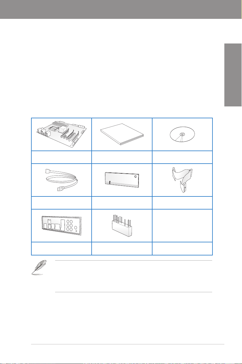
1.2 Package contents
Check your motherboard package for the following items.
ASUS M4A78-E motherboard User guide Support DVD
Chapter 1
4 x Serial ATA signal cables 1 x VGA switch card
ASUS M4A78-E 1-1
1 x Ultra DMA 133/
100/66 cable
1 x Back I/O shield 1 x ASUS Q-Connector kit
• If any of the above items is damaged or missing, contact your retailer.
• The oppy disk drive cable is purchased separately.
• The illustrated items above are for reference only. Actual product specications may
vary with different models.

1.3 Special features
1.3.1 Product highlights
Chapter 1
AMD® Phenom™ X4 / Phenom™ X3 / Athlon™ X2 / Athlon™ / Sempron™
processors (socket AM2+/AM2)socket AM2+/AM2))
This motherboard supports AMD® Socket AM2+ multi-core processors. It features
dual-channel DDR2 1066 memory support, data transfer rate up to 5200MT/s via
HyperTransport™ 3.0 based system bus, and AMD® Cool ‘n’ Quiet™ Technology.
AMD® Phenom™ II / Athlon™ X4 / Athlon™ X3 / Athlon™ X2 (AM3 CPU)Phenom™ II / Athlon™ X4 / Athlon™ X3 / Athlon™ X2 (AM3 CPU) X3 / Athlon™ X2 (AM3 CPU)X3 / Athlon™ X2 (AM3 CPU)(AM3 CPU)AM3 CPU))
This motherboard supports AMD® AM3 multi-core processors with unique L3 cache andmulti-core processors with unique L3 cache and
delivers better overclocking capabilities with less power consumption. It features dualchannel DDR2 1066 memory support and accelerates data transfer rate up to 5200MT/s via
HyperTransport™ 3.0 based system bus. This motherboard also supports AMD. This motherboard also supports AMD® CPUs in the
new 45nm manufacturing process.
AMD® 790GX + SB750 Chipset
AMD® 790GX+SB750 Chipset is designed to support up to 5200MT/s HyperTransport™ 3.0
(HT3.0) interface speed and PCI Express™ 2.0 x 16 graphics. It is optimized with AMD's
latest AM3 and multi-core CPUs to provide excellent system performance and overclocking
capabilities.
ATI Hybrid CrossFireX™ Technology
Boosted Performance with onboard GPU and discrete graphics card
ATI Hybrid CrossFireX™ technology is a unique hybrid multi-GPU technology. It takes your
gaming experience to the next level boosting PC performance by enabling the chipset’s
integrated graphics processor and a discrete GPU to operate simultaneously with combined
output for blisteringly-fast frame rates unleashing the graphics performance
Visit www.amd.com for the Hybrid CrossFireX selected GPUs.
Dual channel DDR2 1066 support
This motherboard supports DDR2 1066, which provides faster data transfer rate and more
bandwidth to increase memory data transfer rate and computing efciency. This enhances
system performance in 3D graphics and other memory demanding applications.
Due to AM2+ / AM3 CPU limitation, only one DDR2 1066 is supported per channel. When
four DDR2 1066 DIMMs are installed, all DIMMs run at 800MHz frequency by default for
system stability.
ATI® CrossFireX™ Technology
ATI’s CrossFireX™ boosts image quality along with rendering speed, eliminating the
need to scale down screen resolution to get high quality images. CrossFireX™ allows
higher antialiasing, anisotropic ltering, shading, and texture settings. Adjust your display
congurations, experiment with the advanced 3D settings, and check the effects with a real-
time 3D-rendered previews within ATI Catalyst™ Control Center.
1-2 Chapter 1: Product Introduction

HDMI support
Enjoy Full HD 1080p Multimedia Home-Theater Entertainment
High-Denition Multimedia Interface (HDMI) is a set of digital video standards that delivers
multi-channel audio and uncompressed digital video for full HD 1080p visuals through a
single cable. Supporting HDCP copy protection such as HD DVD and Blu-ray Discs, HDMI
provides you with the highest-quality home theater experience.
HDMI/DVI/RGB Support
Flexible Graphics Alternatives
This motherboard supports multiple digital and analog display output interfaces - HDMI,
DVI, and D-Sub. With such diversity of display outputs, you are able to choose and upgrade
display devices freely.
1.3.2 ASUS unique features
ASUS Power Solutions
ASUS power solutions intelligently and automatically provide balanced computing power and
energy consumption.
8+1 Phase Power Design
To fully unleash the next-generation AM3 CPU’s potential, the ASUS M4 Series
motherboards have adopted a brand new 8-phase VRM power design. It delivers high
power efciency and supreme overclocking ability. Furthermore, high quality power
components can effectively lower system temperature to ensure longer component
lifespan. This series also features an extra 1 phase power dedicated to integrated
memory/HT controller.
ASUS Anti-Surge Protection
This special design prevents expensive devices and the motherboard from damage
caused by power surges from switching power supply (PSU).
Chapter 1
ASUS Green Design
This motherboard and its packaging comply with the European Union’s Restriction on the
use of Hazardous Substances (RoHS) to safeguard consumers’ health while minimizing the
impact of the environment.
ASUS EPU
The ASUS EPU (Energy Processing Unit) provides total system power management by
detecting current PC loadings and intelligently moderating power usage for critical PC
components in real-time–helping save power and money!
ASUS EPU is supported by AM2+/AM3 CPU only.
AI Nap
With AI Nap, the system can continue running at minimum power and noise when you
are temporarily away. To wake the system and return to the OS environment, simply
click the mouse or press a key.
ASUS M4A78-E 1-3

Express Gate
Taking only 5 seconds to bootup, Express Gate is the one-stop gateway to instant fun! It’s a
Chapter 1
unique motherboard built-in OS. You can utilize the most popular Instant Messengers (IM)
like MSN, Skype, Google talk, QQ, and Yahoo! Messenger to keep in touch with friends,
or quickly check on the weather and e-mails just before leaving your house. What’s more,
the user-friendly picture manager lets you view your pictures without entering Windows at
anytime!
ASUS Quiet Thermal Solutions
ASUS Quiet Thermal solutions make the system more stable and enhance the overclocking
capability.
Fanless Design—Stylish Heatsink Design
The streamline-shaped heatsink features 0-dB thermal solution that offers users a
noiseless PC environment. Not only the beautifully curved ns upgrade the visual
enjoyment for motherboard users, but also the special Streamline Airow Guiding
design lowers the temperature of the north bridge chipset through high efcient
heat-exchange. Combined with usability and aesthetics, the ASUS streamline-shaped
heat-sink will give users an extremely silent and cooling experience with the elegant
appearance!
Q-Fan 2
ASUS Q-Fan 2 technology intelligently adjusts both CPU fan and chassis fan speeds
according to system loading to ensure quiet, cool and efcient operation.
ASUS EZ DIY
ASUS EZ DIY feature collection provides you easy ways to install computer components,
update the BIOS or back up your favorite settings.
The actual boot time is subject to hardware congurations and product models.
ASUS Q-Connector
ASUS Q-Connector allows you to easily connect or disconnect the chassis front panel
cables to the motherboard. This unique module eliminates the trouble of connecting the
system panel cables one at a time and avoiding wrong cable connections.
ASUS O.C. Prole
The motherboard features the ASUS O.C. Prole that allows users to conveniently
store or load multiple BIOS settings. The BIOS settings can be stored in the CMOS or
a separate le, giving users freedom to share and distribute their favorite settings.
ASUS EZ Flash 2
ASUS EZ Flash 2 is a user-friendly BIOS update utility. Simply press the predened
hotkey to launch the utility and update the BIOS without entering the OS. Update your
BIOS easily without preparing a bootable diskette or using an OS-based ash utility.
1-4 Chapter 1: Product Introduction

1.3.3 ASUS intelligent performance and overclocking features
TurboV
Feel the adrenaline rush of real-time OC—now a reality with the ASUS TurboV. This easy OC
tool allows you to overclock without exiting or rebooting the OS; and its user-friendly interface
makes overclock with just a few clicks away. Moreover, the ASUS OC proles in TurboV
provides the best O.C. settings in different scenarios.
Turbo Key
ASUS Turbo Key allows the user to turn the PC power button into a physical overclocking
button. After the easy setup, Turbo Key can boost performances without interrupting ongoing
work or games—with just one touch!
C.P.R. (CPU Parameter Recall)
The C.P.R. feature of the motherboard BIOS allows automatic re-setting to the BIOS default
settings in case the system hangs due to overclocking. When the system hangs due to
overclocking, C.P.R. eliminates the need to open the system chassis and clear the RTC data.
Simply shut down and reboot the system, and the BIOS automatically restores the CPU
default setting for each parameter.
Chapter 1
ASUS M4A78-E 1-5

Chapter 1
1-6 Chapter 1: Product Introduction
Chapter 2
Chapter 2: Hardware information
2.1 Before you proceed
Take note of the following precautions before you install motherboard components or change
any motherboard settings.
• Unplug the power cord from the wall socket before touching any component.
• Before handling components, use a grounded wrist strap or touch a safely grounded
object or a metal object, such as the power supply case, to avoid damaging them due
to static electricity.
• Hold components by the edges to avoid touching the ICs on them.
• Whenever you uninstall any component, place it on a grounded antistatic pad or in the
bag that came with the component.
• Before you install or remove any component, ensure that the ATX power supply is
switched off or the power cord is detached from the power supply. Failure to do so
may cause severe damage to the motherboard, peripherals, or components.
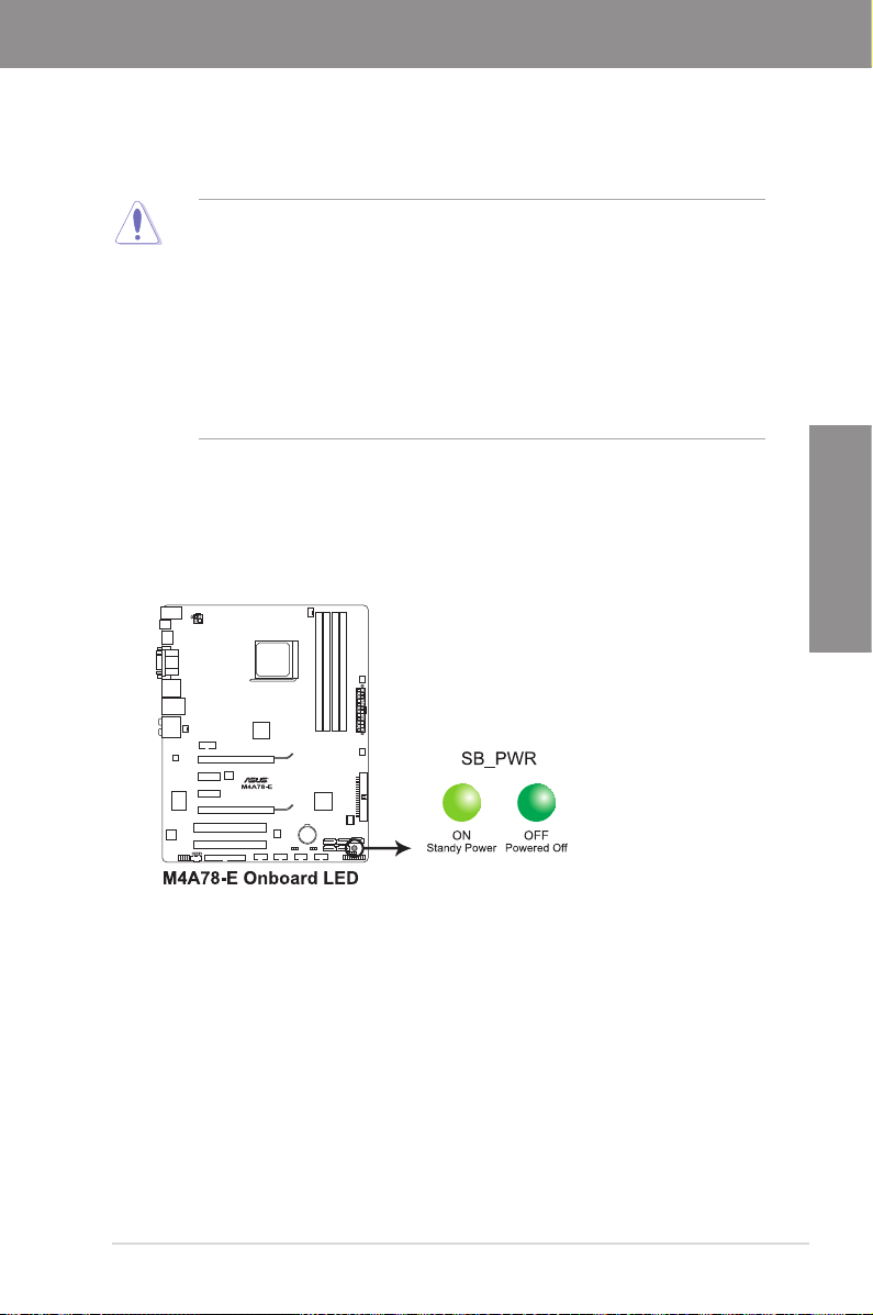
Onboard LED
The motherboard comes with a standby power LED that lights up to indicate that the system
is ON, in sleep mode, or in soft-off mode. This is a reminder that you should shut down
the system and unplug the power cable before removing or plugging in any motherboard
component. The illustration below shows the location of the onboard LED.
Chapter 2
ASUS M4A78-E 2-1
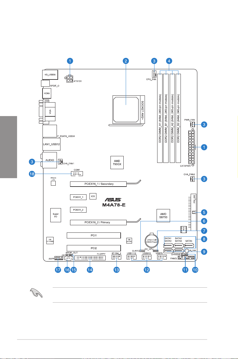
2.2 Motherboard overview
2.2.1 Motherboard layout
Chapter 2
Refer to
2.8 Connectors
connectors.
2-2 Chapter 2: Hardware information
for more information about rear panel connectors and internal
2.2.2 Layout contents
Connectors/Jumpers/Slots Page
1. ATX power connectors (24-pin EATXPWR, 4-pin EATX12V) 2-34
2. AM2/AM2+ CPU socket 2-5
3. CPU, chassis, and power fan connectors
(4-pin CPU_FAN, 3-pin CHA_FAN1–2, 3-pin PWR_FAN)
4. DDR2 DIMM slots 2-10
5. IDE connector (40-1 pin PRI_IDE) 2-28
6. Clear RTC RAM (3-pin CLRTC) 2-21
7. CPU overvoltage setting (3-pin OV_CPU) 2-22
8. AMD® SB750 Serial ATA connectors (7-pin SATA1–5) 2-29
9. Standby Power LED 2-1
10. Chassis intrusion connector (4-1 pin CHASSIS) 2-33
11. System panel connector (20-8 pin PANEL) 2-36
12. USB connectors (10-1 pin USB78, USB910, USB1112) 2-30
13. IEEE 1394a port connector (10-1 pin IE1394_2) 2-31
14. Floppy disk drive connector (34-1 pin FLOPPY) 2-27
15. Digital audio connector (4-1 pin SPDIF_OUT) 2-27
16. Optical drive audio connector (4-pin CD) 2-30
17. Front panel audio connector (10-1 pin AAFP) 2-35
18. Serial port connector (10-1 pin COM1) 2-31
2-32
Chapter 2
ASUS M4A78-E 2-3
2.2.3 Placement direction
When installing the motherboard, ensure that you place it into the chassis in the correct
orientation. The edge with external ports goes to the rear part of the chassis as indicated in
the image below.
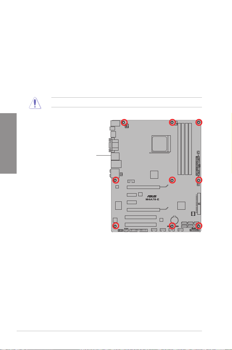
2.2.4 Screw holes
Place nine screws into the holes indicated by circles to secure the motherboard to the
chassis.
Chapter 2
DO NOT overtighten the screws! Doing so can damage the motherboard.
Place this side towards
the rear of the chassis
2-4 Chapter 2: Hardware information
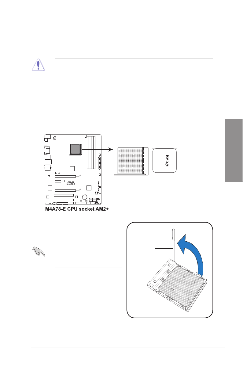
2.3 Central Processing Unit (CPU)
The motherboard comes with an AM2+/AM2 socket designed for Phenom™ X4 /
Phenom™ X3 / Athlon™ X2 / Athlon™/ Sempron™ processors (socket AM2+/AM2). It is also
compatible with AMD® Phenom™ II / Athlon™ X4 / Athlon™ X3 / Athlon™ X2 (AM3 CPU).
The CPU socket is not compatible with AMD® Opteron™ processors. Do not install an
Opteron™ processor on this motherboard.
2.3.1 Installing the CPU
To install a CPU:
1. Locate the CPU socket on the motherboard.
Chapter 2
2. Unlock the socket by pressing the lever
sideways, then lift it up to a 90º angle.
Ensure that the socket lever is lifted
up to a 90º angle; otherwise, the CPU
will not t in completely.
ASUS M4A78-E 2-5
Socket lever
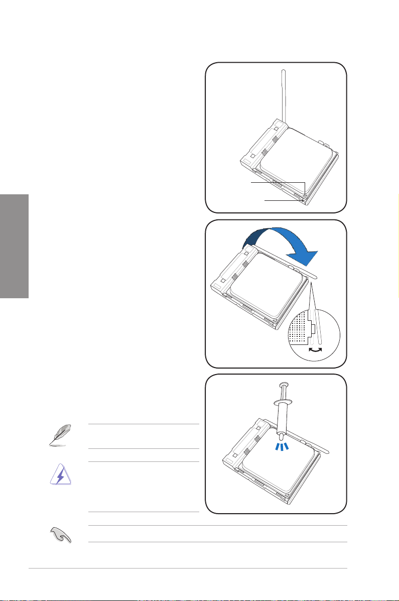
3. Position the CPU above the socket
such that the CPU corner with the gold
triangle matches the socket corner with
a small triangle.
4. Carefully insert the CPU into the socket
until it ts in place.
Chapter 2
5. When the CPU is in place, push down
the socket lever to secure the CPU. The
lever clicks on the side tab to indicate
that it is locked.
Gold triangle
Small triangle
6. Apply some Thermal Interface Material
to the exposed area of the CPU that the
heatsink will be in contact with, ensuring
that it is spread in an even thin layer.
Some heatsinks come with pre-applied
thermal paste. If so, skip this step.
The Thermal Interface Material is
toxic and inedible. If it gets into your
eyes or touches your skin, wash it off
immediately, and seek professional
medical help.
To prevent contaminating the paste, DO NOT spread the paste with your nger.
2-6 Chapter 2: Hardware information
2.3.2 Installing the CPU heatsink and fan
The AMD® AM3/AM2+/AM2 processor requires a specially designed heatsink and fan
assembly to ensure optimum thermal condition and performance.
Ensure that you use only AMD-certied heatsink and fan assembly.
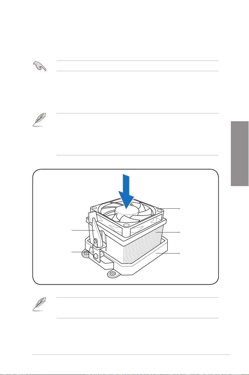
To install the CPU heatsink and fan:
1. Place the heatsink on top of the installed CPU, ensuring that the heatsink ts properly
on the retention module base.
• The retention module base is already installed on the motherboard upon purchase.
• You do not have to remove the retention module base when installing the CPU or
installing other motherboard components.
• If you purchased a separate CPU heatsink and fan assembly, ensure that a Thermal
Interface Material is properly applied to the CPU heatsink or CPU before you install
the heatsink and fan assembly.
CPU fan
Chapter 2
Retention bracket
lock
Retention bracket
Your boxed CPU heatsink and fan assembly should come with installation instructions for
the CPU, heatsink, and the retention mechanism. If the instructions in this section do not
match the CPU documentation, follow the latter.
ASUS M4A78-E 2-7
CPU heatsink
Retention module
base
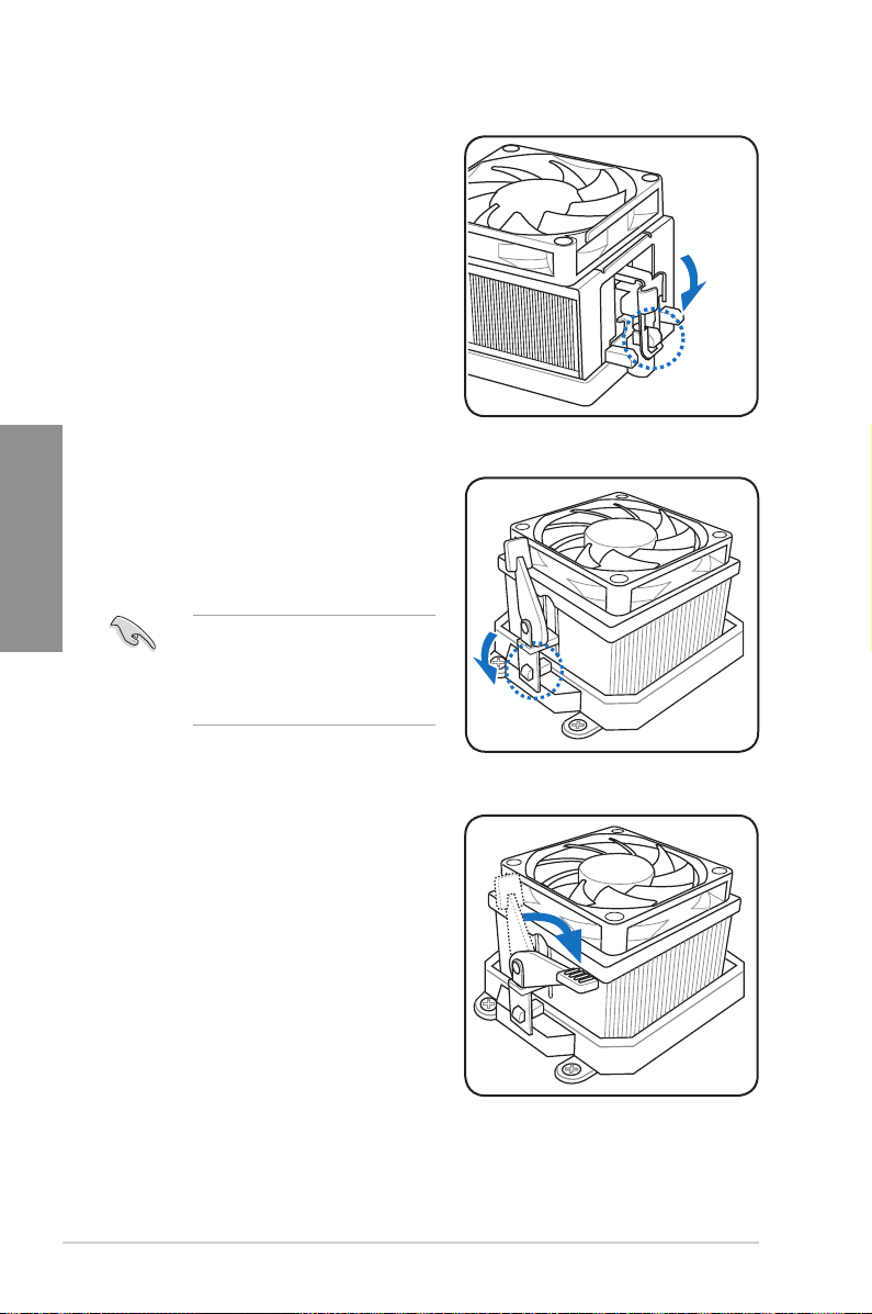
2. Attach one end of the retention bracket
to the retention module base.
Chapter 2
3. Align the other end of the retention
bracket (near the retention bracket lock)
to the retention module base. A clicking
sound denotes that the retention bracket
is in place.
4. Push down the retention bracket lock on
the retention mechanism to secure the
heatsink and fan to the module base.
Ensure that the fan and heatsink
assembly perfectly ts the retention
mechanism module base, otherwise
you cannot snap the retention bracket
in place.
2-8 Chapter 2: Hardware information
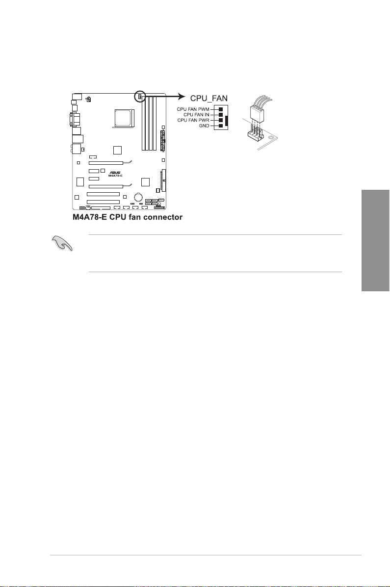
5. When the fan and heatsink assembly is in place, connect the CPU fan cable to the
connector on the motherboard labeled CPU_FAN.
• Do not forget to connect the CPU fan connector! Hardware monitoring errors can
occur if you fail to plug this connector.
• This connector is backward compatible with old 3-pin CPU fan.
Chapter 2
ASUS M4A78-E 2-9
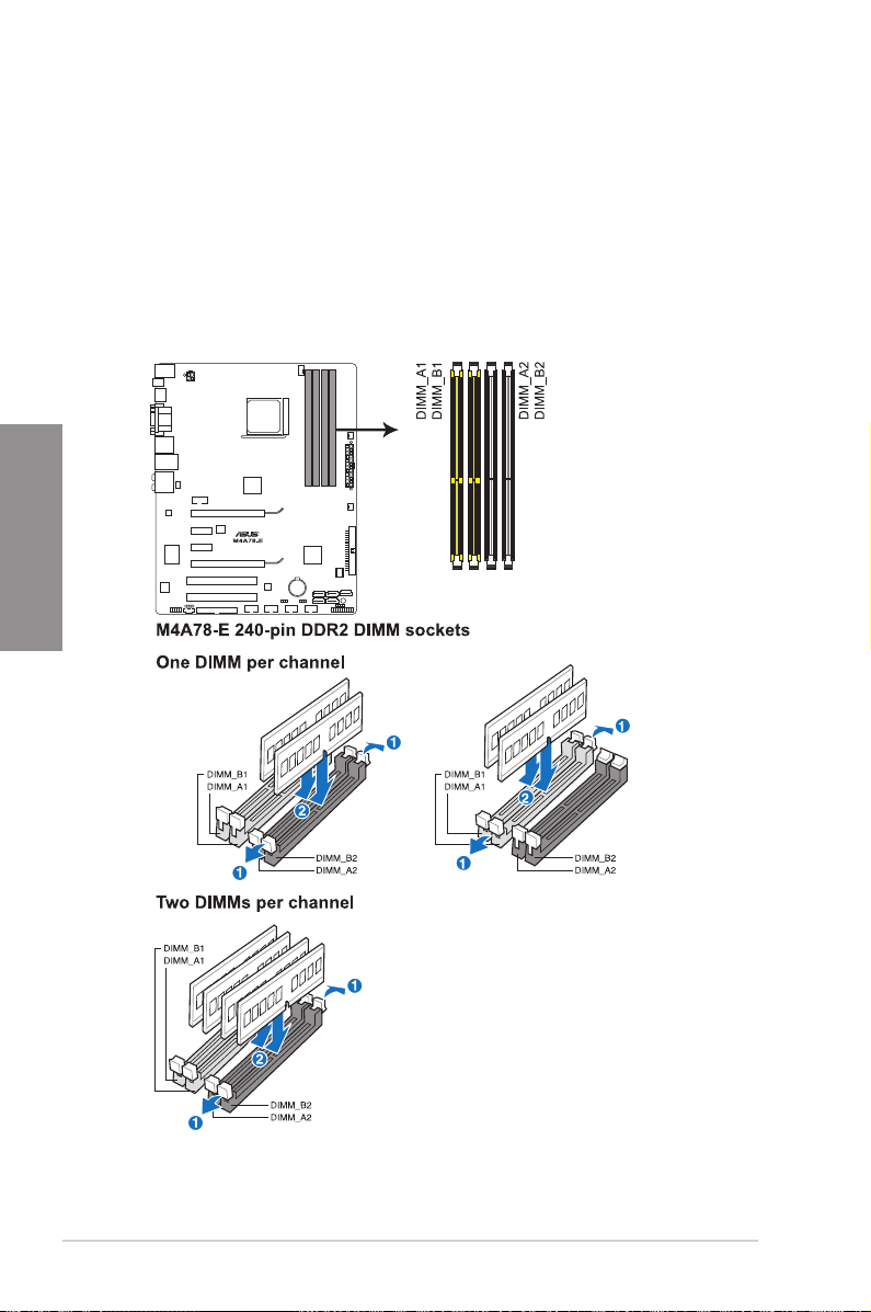
2.4 System memory
2.4.1 Overview
The motherboard comes with four Double Data Rate 2 (DDR2) Dual Inline Memory Modules
(DIMM) sockets.
A DDR2 module has the same physical dimensions as a DDR DIMM but has a 240-pin
footprint compared to the 184-pin DDR DIMM. DDR2 DIMMs are notched differently to
prevent installation on a DDR DIMM socket.
The gure illustrates the location of the DDR2 DIMM sockets:
Chapter 2
2-10 Chapter 2: Hardware information
 Loading...