

V-Series M2A690G
R
R
ASUS PC (Desktop Barebone)
Installation Manual
E306 1
Firs t E diti o n V1
Febr u a r y 20 0 7
Copyright © 2007 ASUSTeK COMPUTER INC. All Rights Reserved.
No part of this manual, including the products and software described in it, may be reproduced,
transmitted, transcribed, stored in a retrieval system, or translated into any language in any form
or by any means, except documentation kept by the purchaser for backup purposes, without the
express written permission of ASUSTeK COMPUTER INC. (“ASUS”).
Product warranty or service will not be extended if: (1) the product is repaired, modied or
altered, unless such repair, modication of alteration is authorized in writing by ASUS; or (2) the
serial number of the product is defaced or missing.
ASUS PROVIDES THIS MANUAL “AS IS” WITHOUT WARRANTY OF ANY KIND, EITHER EXPRESS
OR IMPLIED, INCLUDING BUT NOT LIMITED TO THE IMPLIED WARRANTIES OR CONDITIONS OF
MERCHANTABILITY OR FITNESS FOR A PARTICULAR PURPOSE. IN NO EVENT SHALL ASUS,
ITS DIRECTORS, OFFICERS, EMPLOYEES OR AGENTS BE LIABLE FOR ANY INDIRECT, SPECIAL,
INCIDENTAL, OR CONSEQUENTIAL DAMAGES (INCLUDING DAMAGES FOR LOSS OF PROFITS, LOSS
OF BUSINESS, LOSS OF USE OR DATA, INTERRUPTION OF BUSINESS AND THE LIKE), EVEN IF ASUS
HAS BEEN ADVISED OF THE POSSIBILITY OF SUCH DAMAGES ARISING FROM ANY DEFECT OR
ERROR IN THIS MANUAL OR PRODUCT.
SPECIFICATIONS AND INFORMATION CONTAINED IN THIS MANUAL ARE FURNISHED FOR
INFORMATIONAL USE ONLY, AND ARE SUBJECT TO CHANGE AT ANY TIME WITHOUT NOTICE, AND
SHOULD NOT BE CONSTRUED AS A COMMITMENT BY ASUS. ASUS ASSUMES NO RESPONSIBILITY
OR LIABILITY FOR ANY ERRORS OR INACCURACIES THAT MAY APPEAR IN THIS MANUAL,
INCLUDING THE PRODUCTS AND SOFTWARE DESCRIBED IN IT.
Products and corporate names appearing in this manual may or may not be registered
trademarks or copyrights of their respective companies, and are used only for identication or
explanation and to the owners’ benet, without intent to infringe.
ii
Table of contents
Notices ................................................................................................ vi
Safety information ..............................................................................vii
About this guide .................................................................................viii
System package contents .................................................................... x
Cha p te r 1 : S y ste m I n tro d uc t ion
1.1 Welcome! .............................................................................. 1-2
1.2 Front panel (external) ...........................................................
1.3 Rear panel .............................................................................
1.4 Internal components .............................................................
Cha p te r 2 : Bas i c I nst a ll a tio n
2.1 Preparation ........................................................................... 2-2
2.2 Before you proceed ..............................................................
2.3 Removing the side cover and front panel assembly .............
2.4 Central Processing Unit (CPU) ..............................................
2.4.1 Installing the CPU ....................................................
2.4.2 Installing the CPU fan and heatsink .........................
2.5 Installing a DIMM ...................................................................
2.5.1 Memory congurations ...........................................
2.5.2 Installing a DDR2 DIMM .........................................
2.5.3 Removing a DDR2 DIMM ........................................
2.6 Expansion slots ...................................................................
2.6.1 Installing an expansion card ..................................
2.6.2 Conguring an expansion card ..............................
2.6.3 PCI Express x1 slot ...............................................
2.6.4 PCI slots ................................................................
2.6.5 PCI Express x16 slot .............................................
2.7 Installing an optical drive ....................................................
2.8 Installing a hard disk drive ..................................................
2.9 Installing the card reader ....................................................
2.10 Installing a oppy disk drive
2.11 Re-connecting cables ..........................................................
2.12 Reinstalling the cover .........................................................
................................................ 2-20
1-2
1-4
1-7
2-2
2-3
2-4
2-4
2-6
2-8
2-8
2-11
2-11
2-12
2-12
2-12
2-14
2-14
2-14
2-15
2-16
2-18
2-21
2-22
iii
Table of contents
Cha p te r 3 : Sta r ti n g u p
3.1 Installing an operating system .............................................. 3-2
3.2 Powering up ..........................................................................
3.3 Support CD information ........................................................
3.3.1 Running the support CD ..........................................
3.3.2 Utilities menu ..........................................................
3.3.3 Make disk ................................................................
3.3.4 ASUS contact information ......................................
3.4 Software information ............................................................
Cha p te r 4 : Mot h er b oar d I n fo
4.1 Introduction .......................................................................... 4-2
4.2 Motherboard layout ..............................................................
4.3 Jumpers ................................................................................
4.4 Connectors ...........................................................................
Cha p te r 5 : BIO S I n for m at i on
5.1 Managing and updating your BIOS ........................................ 5-2
5.1.1 Creating a bootable oppy disk ..............................
5.1.2 ASUS EZ Flash 2 utility ............................................
5.1.3 AwardBIOS Flash utility ...........................................
5.1.4 ASUS CrashFree BIOS 2 utility ................................
5.1.5 ASUS Update utility ................................................
3-2
3-2
3-3
3-4
3-5
3-5
3-6
4-2
4-3
4-5
5-2
5-3
5-4
5-6
5-8
5.2 BIOS setup program ............................................................
5.2.1 BIOS menu screen .................................................
5.2.2 Menu bar ...............................................................
5.2.3 Legend bar ............................................................
5.2.4 Menu items ...........................................................
5.2.5 Sub-menu items ....................................................
5.2.6 Conguration elds ...............................................
5.2.7 Pop-up window ......................................................
5.2.8 General help ..........................................................
iv
5-11
5-11
5-11
5-12
5-12
5-12
5-12
5-13
5-13

Table of contents
5.3 Main menu ........................................................................... 5-14
5.3.1 System Time ........................................................
5.3.2 System Date ........................................................
5.3.3 Legacy Diskette A ...............................................
5.3.4 Primary IDE Master/Slave ......................................
5.3.5 SATA 1-4 ..............................................................
5.3.6 HDD SMART Monitoring .........................................
5.3.7 Installed Memory ...................................................
5.3.8 Usable Memory ......................................................
5.4 Advanced menu ..................................................................
5.4.1 JumperFree Conguration .....................................
5.4.2 CPU Conguration .................................................
5.4.3 Chipset ..................................................................
5.4.4 PCIPnP ...................................................................
5.4.5 Onboard Device Conguration ..............................
5.4.6 USB Conguration .................................................
5.5 Power menu ........................................................................
5.5.1 ACPI Suspend Type ...............................................
5.5.2 ACPI APIC Support ................................................
5.5.3 APM Conguration ................................................
5.5.4 Hardware Monitor ..................................................
5.6 Boot menu ..........................................................................
5.6.1 Boot Device Priority ..............................................
5.6.2 Removable Drives ..................................................
5.6.3 Hard Disk Drives ....................................................
5.6.4 Boot Settings Conguration .................................
5.6.5 Security .................................................................
5.7 Tools menu .........................................................................
5.7.1 ASUS Music Alarm .................................................
5.7.2 ASUS O.C. Prole ..................................................
5.7.3 ASUS EZ Flash 2 ....................................................
5.8 Exit menu ............................................................................
5-14
5-14
5-14
5-15
5-16
5-17
5-18
5-18
5-18
5-19
5-20
5-21
5-22
5-23
5-25
5-26
5-26
5-26
5-26
5-28
5-30
5-30
5-30
5-31
5-31
5-33
5-34
5-34
5-36
5-38
5-31
v
Notices
Fed er al Co mm un ica ti on s C om mi ssi on S tat em en t
This device complies with Part 15 of the FCC Rules. Operation is subject to
the following two conditions:
•
This device may not cause harmful interference, and
•
This device must accept any interference received including
interference that may cause undesired operation.
This equipment has been tested and found to comply with the limits for a
Class B digital device, pursuant to Part 15 of the FCC Rules. These limits
are designed to provide reasonable protection against harmful interference
in a residential installation. This equipment generates, uses and can radiate
radio frequency energy and, if not installed and used in accordance with
manufacturer’s instructions, may cause harmful interference to radio
communications. However, there is no guarantee that interference will
not occur in a particular installation. If this equipment does cause harmful
interference to radio or television reception, which can be determined by
turning the equipment off and on, the user is encouraged to try to correct
the interference by one or more of the following measures:
•
Reorient or relocate the receiving antenna.
•
Increase the separation between the equipment and receiver.
•
Connect the equipment to an outlet on a circuit different from that to
which the receiver is connected.
•
Consult the dealer or an experienced radio/TV technician for help.
WARNING! The use of shielded cables for connection of the monitor to
the graphics card is required to assure compliance with FCC regulations.
Changes or modications to this unit not expressly approved by the
party responsible for compliance could void the user’s authority to
operate this equipment.
Can ad ia n D ep ar tme nt o f C om mu nic at io ns St at eme nt
This digital apparatus does not exceed the Class B limits for radio noise
emissions from digital apparatus set out in the Radio Interference
Regulations of the Canadian Department of Communications.
This class B digital apparatus complies with Canadian ICES-003.
vi
Safety information
Ele ct ri cal s af ety
•
To prevent electrical shock hazard, disconnect the power cable from
the electrical outlet before relocating the system.
•
When adding or removing devices to or from the system, ensure that
the power cables for the devices are unplugged before the signal cables
are connected.
•
If the power supply is broken, do not try to fix it by yourself. Contact a
qualified service technician or your retailer.
Ope ra ti on sa fe ty
•
Before installing devices into the system, carefully read all the
documentation that came with the package.
•
Before using the product, make sure all cables are correctly connected
and the power cables are not damaged. If you detect any damage,
contact your dealer immediately.
•
To avoid short circuits, keep paper clips, screws, and staples away from
connectors, slots, sockets and circuitry.
•
Avoid dust, humidity, and temperature extremes. Do not place the
product in any area where it may become wet. Place the product on a
stable surface.
•
If you encounter technical problems with the product, contact a
qualified service technician or your retailer.
Lithium-Ion Battery Warning
CAUTION: Danger of explosion if battery is incorrectly replaced.
Replace only with the same or equivalent type recommended by
the manufacturer. Dispose of used batteries according to the
manufacturer’s instructions.
VORSICHT: Explosionsgetahr bei unsachgemäßen Austausch der
Batterie. Ersatz nur durch denselben oder einem vom Hersteller
empfohlenem ähnljchen Typ. Entsorgung gebrauchter Batterien nach
Angaben des Herstellers.
LASER PRODUCT WARNING
CLA SS 1 LA SE R PRO DU CT
vii
About this guide
Aud ie nc e
This guide provides general information and installation instructions about
the ASUS Vintage V-Series M2A690G barebone system. This guide is
intended for experienced users and integrators with hardware knowledge of
personal computers.
How t hi s g ui de is o rg ani ze d
This guide contains the following parts:
1. Chap t e r 1: S y s tem i n t rodu c t i on
This chapter gives a general description of the ASUS
V-Series M2A690G. The chapter lists the system features, including
introduction on the front and rear panel, and internal components.
2. Chap t e r 2: B a s ic i n s t alla t i o n
This chapter provides step-by-step instructions on how to install
components in the system.
3. Chap t e r 3: S t a rtin g u p
This chapter helps you power up the system and install drivers and
utilities from the support CD.
4. Chap t e r 4: M o t herb o a r d in f o r mati o n
This chapter gives information about the motherboard that comes
with the system. This chapter includes the motherboard layout,
jumper settings, and connector locations.
5. Chap t e r 5: B I O S in f o r mati o n
This chapter tells how to change system settings through the BIOS
Setup menus and describes the BIOS parameters.
viii
Con ve nt ion s us ed in t his g ui de
WARNING: Information to prevent injury to yourself when trying
to complete a task.
CAUTION: Information to prevent damage to the components
when trying to complete a task.
IMPORTANT: Instructions that you MUST follow to complete a
task.
NOTE: Tips and additional information to aid in completing a
task.
Whe re t o f in d mor e in for ma ti on
Refer to the following sources for additional information and for product
and software updates.
1. ASUS W e bsit e s
The ASUS websites worldwide provide updated information on
ASUS hardware and software products. Refer to the ASUS contact
information.
2. Opti o n a l Do c u m enta t i o n
Your product package may include optional documentation, such as
warranty yers, that may have been added by your dealer. These
documents are not part of the standard package.
ix
System package contents
Check your V-Series M2A690G system package for the following items.
If any of the items is damaged or missing, contact your retailer
immediately.
Ite m d escri p t i on
1. ASUS V-Series M2A690G barebone system with
• ASUS motherboard
• Power supply unit
• ASUS chassis
2. Cable
• AC power cable
3. Support CD
4. User guide
An optional card reader is available along with the system for the users
to purchase.
x

R
R
Chapter 1
This chapter gives a general
description of the ASUS
V-Series M2A690G. The chapter
lists the system features including
introduction on the front and rear
panel, and internal components.
System introduction
1.1 Welcome!
R
Thank you for choosing the ASUS V-Series M2A690G!
The ASUS V-Series M2A690G is an all-in-one barebone system with a
versatile home entertainment feature.
The system comes in a stylish casing and powered by the ASUS
motherboard with the AMD Socket M2 that supports the AMD
®
Athlon™
64X2 / Athlon™64 / Sempron™ processors.
The system supports up to 4 GB of system memory using
DDR2-800/667/533 DIMMs. High-resolution graphics via Nividia on board
Gfx or PCI Express x16 slot, Serial ATA, USB 2.0, and
8-channel audio feature the system and take you ahead in the world of
power computing.
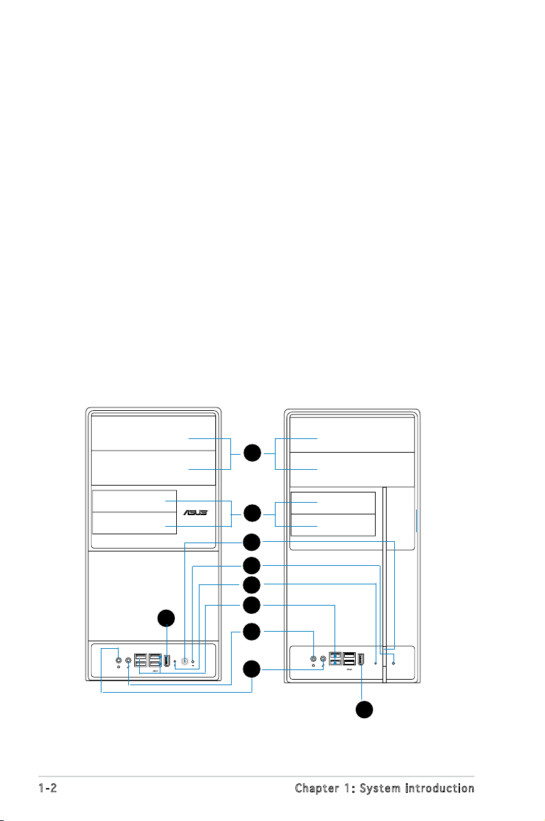
1.2 Front panel
The front panel includes the optical drive bays, oppy disk drive slot, power
button, and several I/O ports are located at the front panel.
1
2
3
4
5
9
1-2 Chapter 1: System introduction
6
7
8
9
1. Two empty 5.25-inch bays. These bays are for IDE optical drives.
2. 3.5-inch drive bays. These slots are for 3.5-inch oppy or hard disk
drives.
3. Power button. Press this button to turn the system on.
4. Reset button. Press this button to reboot the system without turning
off the power.
5. HDD LED. This LED lights up when data is read from or written to the
hard disk drive.
6. USB 2.0 ports. These Universal Serial Bus 2.0 (USB 2.0) ports are
available for connecting USB 2.0 devices such as a mouse, printer,
scanner, camera, PDA, and others.
7. Headphone port. This Line In (green) port connects a headphone with
a stereo mini-plug.
8. Microphone port. This Mic (pink) port connects a microphone.
9. IEEE1394 port.
This V-series provide V2/V3 two types of front panel for users to
choose, please refer to your product package for the front panel type
you purchased.
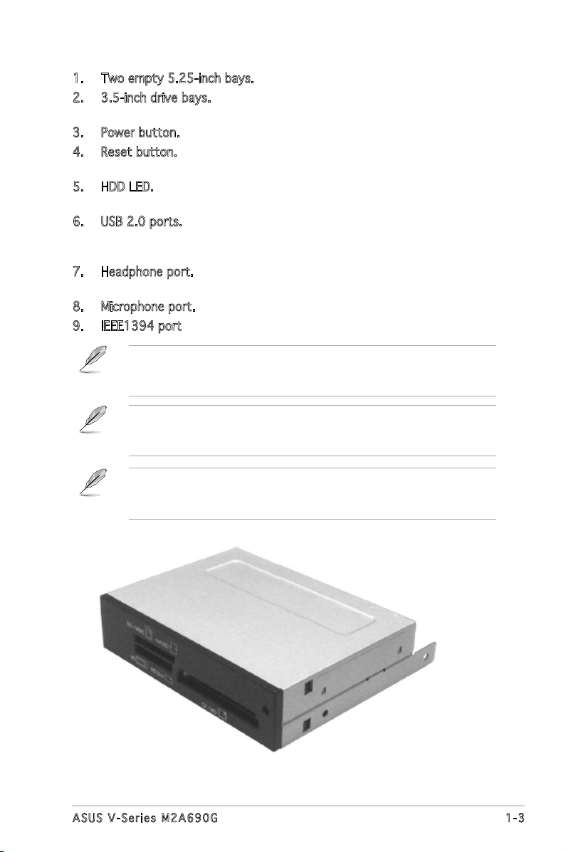
PCI Express Graphics Slot supports most of the ATi® and NVDIA® graphics
cards, except some ATi® graphics cards of old version, such as ATi®
X300, X550, X700, and X800 series.
An optional Card Reader (see the gure bellow) available. It is to be
installed in the 3.5-inch drive bay, and connected to the motherboard
through a USB cable.
1-3ASUS V-Series M2A690G
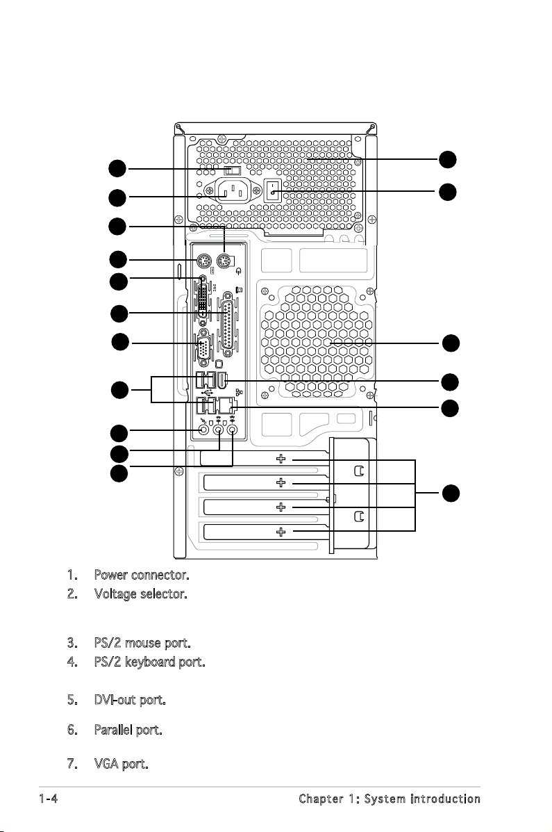
1.3 Rear panel
1394
The system rear panel includes the power connector and several I/O ports
that allow convenient connection of devices.
2
1
3
10
11
12
17
4
5
6
7
8
9
13
14
15
16
1. Power connector. This connector is for the power cable and plug.
2. Voltage selector. This switch allows you to adjust the system input
voltage according to the voltage supply in your area. See the section
“Voltage selector” on page 1-6 before adjusting this switch.
3. PS/2 mouse port. This green 6-pin connector is for a PS/2 mouse.
4. PS/2 keyboard port. This purple 6-pin connector is for a
PS/2 keyboard.
5. DVI-out port. This port connects a Digital Visual Interface (DVI-D)
card.
6. Parallel port. This 25-pin port connects a printer, scanner, or other
devices.
7. VGA port. This port connects a VGA monitor.
1-4 Chapter 1: System introduction
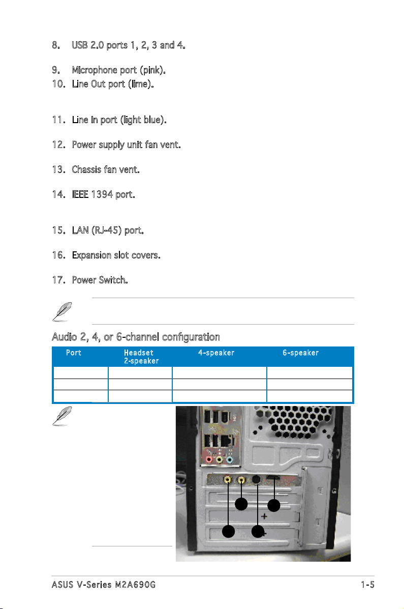
8. USB 2.0 ports 1, 2, 3 and 4. These 4-pin Universal Serial Bus (USB)
ports are available for connecting USB 2.0 devices.
9. Microphone port (pink). This port connects a microphone.
10. Line Out port (lime). This port connects a headphone or a speaker.
In 4-channel and 6-channel conguration, the function of this port
becomes Front Speaker Out.
11. Line In port (light blue). This port connects the tape, CD, DVD player,
or other audio sources.
12. Power supply unit fan vent. This vent is for the PSU fan that provides
ventilation inside the power supply unit.
13. Chassis fan vent. This vent is for the fan that provides ventilation
inside the system chassis.
14. IEEE 1394 port. This 6-pin IEEE 1394 port provides high-speed
connectivity for audio/video devices, storage peripherals, PCs, or
portable devices.
15. LAN (RJ-45) port. This port allows Gigabit connection to a Local Area
Network (LAN) through a network hub.
16. Expansion slot covers. Remove these covers when installing expansion
cards.
17. Power Switch. This switch is for switching on/off the power supply
unit.
Refer to the audio conguration table below for the function of the audio
ports in 2, 4, or 6-channel conguration.
Audio 2, 4, or 6-channel conguration
Por t He adse t 4-s p e a ker 6- s p eake r
2-spe a k e r
Light Blue Line In Surround Out Surround Out
Lime Line Out Front Speaker Out Front Speaker Out
Pink Mic In Mic In Center/Bass
A HDMI card is
avialbe along with
the system. It is to
be installed on the
PCI Express x 16 slot
on the motherboard.
After it is installed,
the ports of the HDMI
card in the expansion
slot area on the rear
panel as shown. Refer
to the next page for
the descriptions for
the HDMI card ports.
C
D
A
B
1-5ASUS V-Series M2A690G
HDM I ca rd po rt s
A. HDMI port. This port is for a high-denition multimedia interface
(HDMI) connector.
B. S-Video port / YPbPr port. This 7-pin port connects any kind of video
source via a YPbPr cable or an S-Video cable.
C. Video port. This port connects any kind of video source via an RCA
cable.
D. S/PDIF Out port. This port connects an external audio output device
via an coaxial S/PDIF cable.
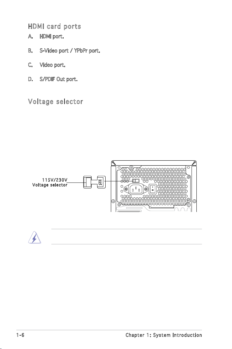
Vol ta ge se le ct or
The PSU has a 115 V/230 V voltage selector switch located beside the
power connector. Use this switch to select the appropriate system input
voltage according to the voltage supply in your area.
If the voltage supply in your area is 100-127 V, set this switch to 115 V.
If the voltage supply in your area is 200-240 V, set this switch to 230 V.
115 V / 2 30V
Vol t a g e sel e c t or
Setting the switch to 115V in a 230V environment or 230V in a 115V
environment will seriously damage the system!
1-6 Chapter 1: System introduction
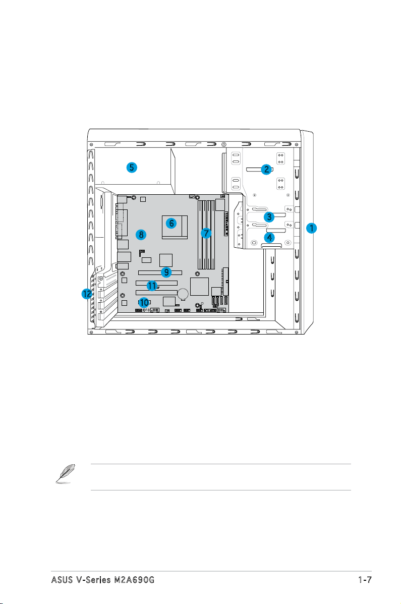
1.4 Internal components
R
The illustration below is the internal view of the system when you remove
the top cover and the power supply unit. The installed components are
labeled for your reference. Proceed to Chapter 2 for instructions on
installing additional system components.
5
6
8
9
11
12
10
1. Front panel cover
2. 5.25-inch optical drive bays
3. Floppy disk drive bay
4. Hard disk drive bay
5. Power supply unit
6. CPU socket
7. DIMM sockets
2
3
7
4
8. ASUS motherboard
9. PCI Express x16 slot
10. PCI Express x1 slot
11. PCI slots
12. Metal bracket lock
1
There is a HDMI module supplying along with the system. Refer to the
chapter 2 for the detailed information about the HDMI module.
1-7ASUS V-Series M2A690G
1-8 Chapter 1: System introduction
R
R
Chapter 2
This chapter provides step-by-step
instructions on how to install
components in the system.
Basic installation
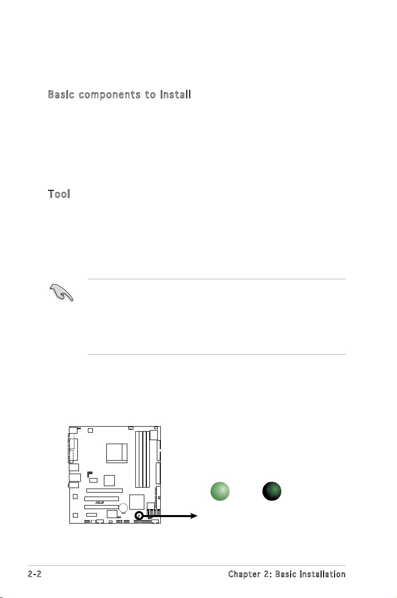
2.1 Preparation
R
Onboard LED
SB_PWR
ON
Standby
Power
OFF
Powered
Off
M2A-VM
Before you proceed, make sure that you have all the components you plan
to install in the system.
Bas i c c omp o ne n ts t o i nst a ll
1. Central Processing Unit (CPU)
2. DDR2 Dual Inline Memory Module (DIMM)
3. Expansion card(s)
4. Hard disk drive
5. Optical drive
6. Floppy disk drive
Too l
Phillips (cross) screw driver
2.2 Before you proceed
Take note of the following precautions before you install components into
the system.
•
Use a grounded wrist strap or touch a safely grounded object or
a metal object, such as the power supply case, before handling
components to avoid damaging them due to static electricity.
•
Hold components by the edges to avoid touching the ICs on them.
•
Whenever you uninstall any component, place it on a grounded
antistatic pad or in the bag that came with the component.
The motherboard comes with an onboard standby power LED. This LED
lights up to indicate that the system is ON, in sleep mode or in soft-off
mode, and not powered OFF. Unplug the power cable from the power outlet
and make sure that the standby power LED is OFF before installing any
system component.
2-2 Chapter 2: Basic installation
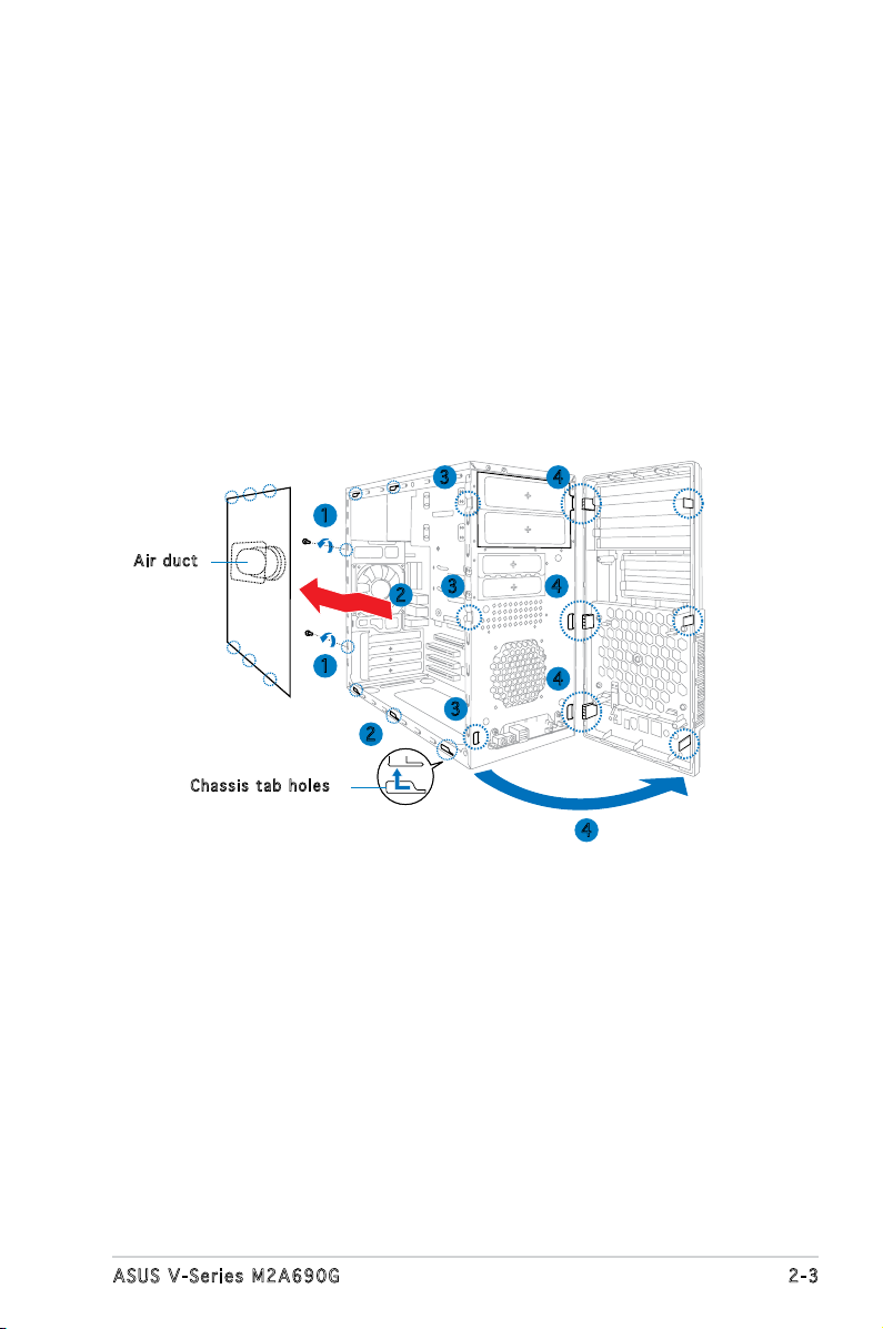
2.3 Removing the side cover and front
panel assembly
1. Remove the cover screws on the rear panel.
2. Pull the side cover toward the rear panel until its hooks disengage
from the chassis tab holes. Set the side cover aside.
3. Locate the front panel assembly hooks, then lift them until they
disengage from the chassis.
4. Swing the front panel assembly to the right, until the hinge-like tabs
on the right side of the assembly are exposed.
5. Remove the front panel assembly, then set aside.
3 4
1
Air d u ct
3
2
4
Cha s s i s tab h o les
1
3
2
4
4
2-3ASUS V-Series M2A690G
2.4 Central Processing Unit (CPU)
R
CPU Socket M2
M2A-VM
The motherboard comes with a 940-pin AM2 socket designed for the AMD
Athlon™ 64 X2/Athlon™ 64/Sempron™ processor.
The AM2 socket has a different pinout from the 940-pin socket designed
for the AMD Opteron™ processor. Make sure you use a CPU is designed
for the AM2 socket. The CPU ts in only one correct orientation. DO NOT
force the CPU into the socket to prevent bending the connectors on the
socket and damaging the CPU!
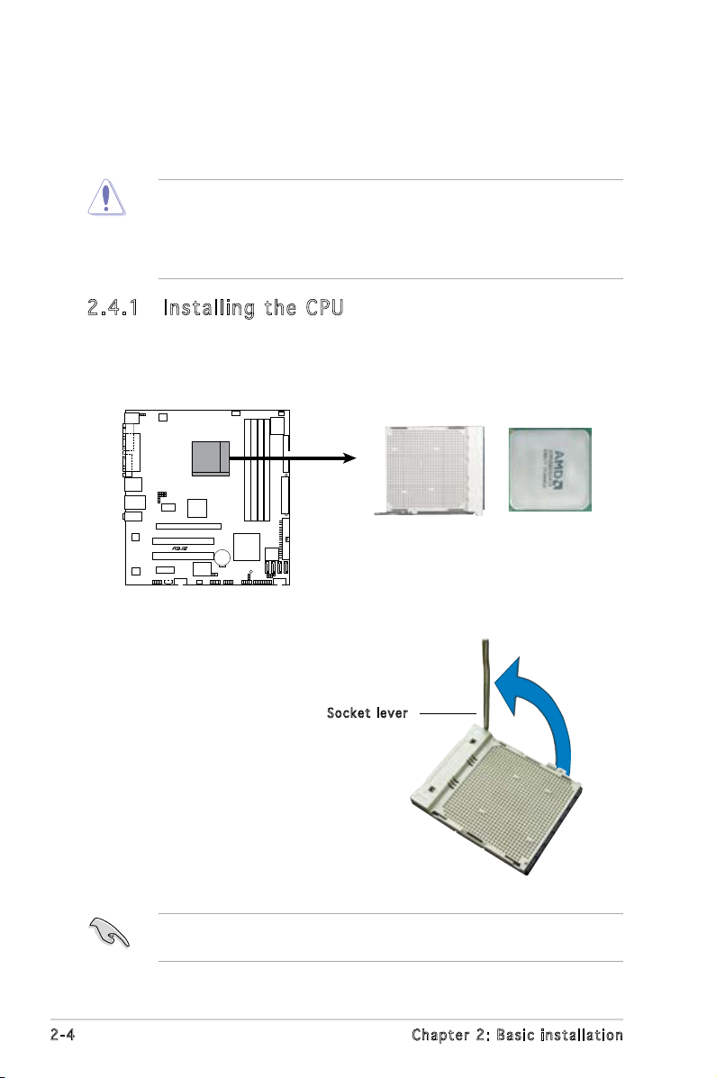
2.4 .1 Ins ta ll ing t he CP U
To install a CPU:
1. Locate the CPU socket on the motherboard.
2. Unlock the socket by pressing
the lever sideways, then lift it up
to a 90º angle.
Make sure that the socket lever is lifted up to a 90º angle; otherwise,
the CPU will not t in completely.
2-4 Chapter 2: Basic installation
Soc k e t leve r
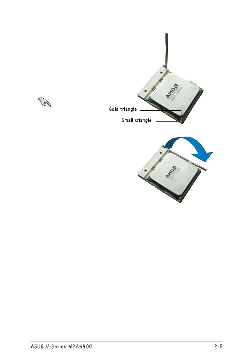
3. Position the CPU above the
socket such that the CPU corner
with the gold triangle matches
the socket corner with a small
triangle.
4. Carefully insert the CPU into the
socket until it ts in place.
Please make sure
your CPU is fully
plugged-in to reduce
abnormal symptom.
Gol d t riang l e
Sma l l trian g l e
5. When the CPU is in place, push
down the socket lever to secure
the CPU. The lever clicks on the
side tab to indicate that it is
locked.
6. Install a CPU heatsink and fan
following the instructions that
came with the heatsink package.
2-5ASUS V-Series M2A690G
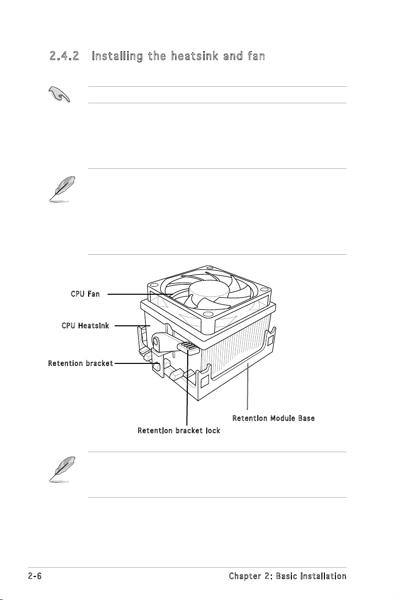
2.4 .2 Ins ta ll ing t he he at si nk an d fan
Make sure that you use only AMD-certied heatsink and fan assembly.
Follow these steps to install the CPU heatsink and fan.
1. Place the heatsink on top of the installed CPU, making sure that the
heatsink ts properly on the retention module base.
• The retention module base is already installed on the motherboard
upon purchase.
• You do not have to remove the retention module base when
installing the CPU or installing other motherboard components.
• If you purchased a separate CPU heatsink and fan assembly, make
sure that a Thermal Interface Material is properly applied to the CPU
heatsink or CPU before you install the heatsink and fan assembly.
CPU F a n
CPU H e atsin k
Ret e n t ion b r a c ket
Ret e n t ion M o d u le Ba s e
Ret e n t ion b r a c ket l o c k
Your boxed CPU heatsink and fan assembly should come with installation
instructions for the CPU, heatsink, and the retention mechanism. If the
instructions in this section do not match the CPU documentation, follow
the latter.
2-6 Chapter 2: Basic installation
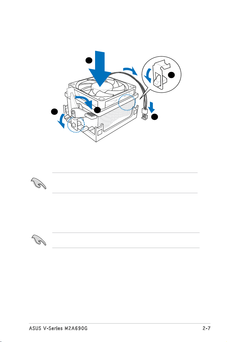
2. Attach one end of the retention bracket to the retention module base.
1
3
4
5
2
3. Align the other end of the retention bracket (near the retention
bracket lock) to the retention module base. A clicking sound denotes
that the retention bracket is in place.
Make sure that the fan and heatsink assembly perfectly ts the
retention mechanism module base, otherwise you cannot snap the
retention bracket in place.
4. Push down the retention bracket lock on the retention mechanism to
secure the heatsink and fan to the module base.
5. When the fan and heatsink assembly is in place, connect the CPU fan
cable to the connector on the motherboard labeled CPU_FAN.
Do not forget to connect the CPU fan connector! Hardware monitoring
errors can occur if you fail to plug this connector.
2-7ASUS V-Series M2A690G
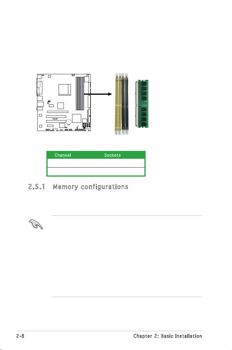
2.5 Installing a DIMM
R
240-pin DDR2 DIMM Sockets
112 Pins
128 Pins
DIMM_A1
DIMM_A2
DIMM_B1
DIMM_B2
M2A-VM
The system motherboard comes with four Double Data Rate 2 (DDR2) Dual
Inline Memory Module (DIMM) sockets.
The following gure illustrates the location of the sockets:
Ch a n nel Sock e t s
Channel A DIMM_A1 and DIMM_A2
Channel B DIMM_B1 and DIMM_B2
2.5 .1 Mem or y con fi gu rat io ns
You may install up to 4 GB system memory using 256 MB, 512 MB, 1 GB,
and 2 GB unbuffered ECC/non-ECC DDR2 DIMMs.
• For dual-channel conguration, the total size of memory module(s)
installed per channel must be the same (DIMM_A1 + DIMM_A2 =
DIMM_B1 + DIMM_B2).
• Always install DIMMs with the same CAS latency. For optimum
compatibility, it is recommended that you obtain memory modules
from the same vendor. Refer to the DDR2 Qualied Vendors List for
details.
• Some odd version DDR2-667 DIMMs may not match Intel On-DieTemination (0DT) requirement and may downgrade to run at DDR2-533. If
this happen, contact your retailer for the ODT value.
• This motherboard does not support memory modules made up of
128 Mb chips.
2-8 Chapter 2: Basic installation
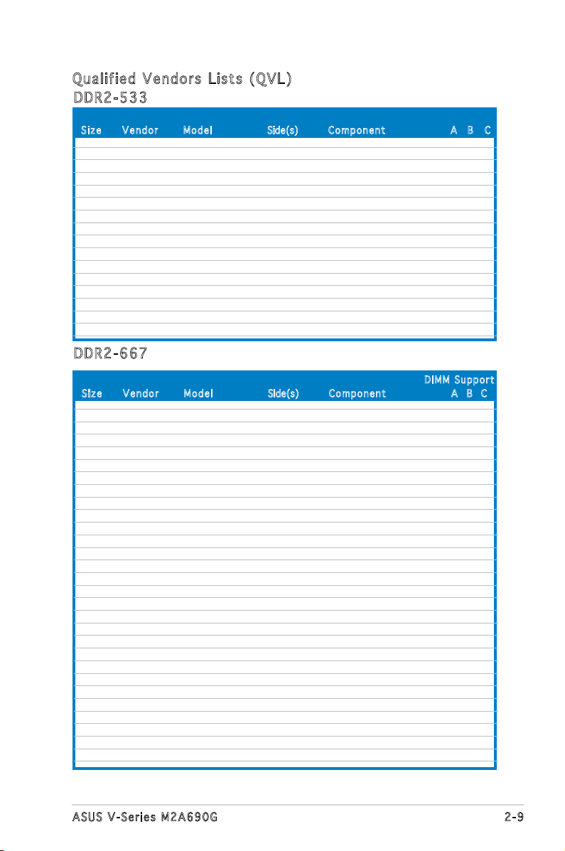
Qua l if i ed V en d ors Li s ts ( QV L )
DDR 2 -53 3
Siz e Ve n d o r Mod e l Side(s) Com p o n ent A B C
256MB KINGSTON E5116AF-5C-E SS KVR533D2N4/256 V V V
512MB KINGSTON HYB18T512800AF37 SS KVR533D2N4/512 V V V
1024MB KINGSTON 5YDIID9GCT DS KVR533D2N4/1G V V V
512MB Qimonda HYB18T512800BF37 SS HYS64T64000HU-3.7-B V V V
1024MB Qimonda HYB18T512800BF37 DS HYS64T128020HU-3.7-B V V V
256MB SAMSUNG K4T51163QC-ZCD5 SS M378T3354CZ3-CD5 V V V
512MB SAMSUNG ZCD5K4T51083QC SS M378T6553CZ3-CD5 V V V
1024MB SAMSUNG ZCD5K4T51083QC DS M378T2953CZ3-CD5 V V V
256MB Hynix HY5PS121621CFP-C4 SS HYMP532U64CP6-C4 V V V
1024MB Hynix HY5PS12821CFP-C4 DS HYMP512U64CP8-C4 V V V
256MB CORSAIR 32M16CEDG SS VS256MB533D2 V V V
512MB CORSAIR MI110052432M8CEC DS VS512MB533D2 V V V
1024MB CORSAIR 64M8CEDG DS VS1GB533D2 V V V
512MB ELPIDA E5108AB-5C-E(ECC) SS EBE51ED8ABFA-5C-E V V V
512MB ELPIDA E5108AB-5C-E SS EBE51UD8ABFA-5C V V V
512MB ELPIDA E5108AB-5C-E SS EBE51UD8ABFA-5C-E V V V
DDR 2 -66 7
Siz e Ve n d o r Mod e l Side(s) C o m ponen t A B C
DIM M S uppor t
512MB KINGSTON D6408TEBGGL3U SS KVR667D2N5/512 V V V
1024MB KINGSTON D6408TEBGGL3U DS KVR667D2N5/1G V V V
256MB KINGSTON HYB18T256800AF3S SS KVR667D2N5/256 V V
1024MB Qimonda HYB18T512800BF3S(ECC) DS HYS72T128020HU-3S-B V V V
256MB Qimonda HYB18T512160BF-3S SS HYS64T32000HU-3S-B V V V
512MB Qimonda HYB18T512800BF3S SS HYS64T64000HU-3S-B V V V
1024MB Qimonda HYB18T512800BF3S DS HYS64T128020HU-3S-B V V V
512MB SAMSUNG ZCE6K4T51083QC SS M378T6553CZ0-CE6 V V V
256MB SAMSUNG K4T51163QC-ZCE6 SS M378T3354CZ3-CE6 V V V
512MB SAMSUNG K4T51083QC SS M378T6553CZ3-CE6 V V V
1024MB SAMSUNG ZCE6K4T51083QC DS M378T2953CZ3-CE6 V V V
256MB CORSAIR MIII00605 SS VS256MB667D2 V
512MB CORSAIR 64M8CFEG SS VS512MB667D2 V V V
1024MB CORSAIR 64M8CFEG DS VS1GB667D2 V
256MB ELPIDA E2508AB-6E-E SS EBE25UC8ABFA-6E-E V V V
512MB ELPIDA E5108AE-6E-E SS EBE51UD8AEFA-6E-E V V V
512MB A-DATA AD29608A8A-3EG SS M2OAD5G3H3166I1C52 V V V
1024MB A-DATA AD29608A8A-3EG DS M2OAD5G3I4176I1C52 V V
512MB crucial Heat-Sink Package SS BL6464AA663.8FD
1024MB crucial Heat-Sink Package DS BL12864AA663.16FD
1024MB crucial Heat-Sink Package DS BL12864AL664.16FD V V V
1024MB crucial Heat-Sink Package DS BL12864AA663.16FD2
512MB Apacer AM4B5708GQJS7E0628F SS AU512E667C5KBGC V
1024MB Apacer AM4B5708GQJS7E DS AU01GE667C5KBGC V
256MB Kingmax N2TU51216AG-3C SS KLCB68F-36KH5 V V V
512MB Kingmax KKEA88B4LAUG-29DX SS KLCC28F-A8KB5 V V
1024MB Kingmax KKEA88B4LAUG-29DX DS KLCD48F-A8KB5 V
512MB Transcend E5108AE-6E-E SS TS64MLQ64V6J V V
1024MB Transcend E5108AE-6E-E DS TS128MLQ64V6J V
2-9ASUS V-Series M2A690G
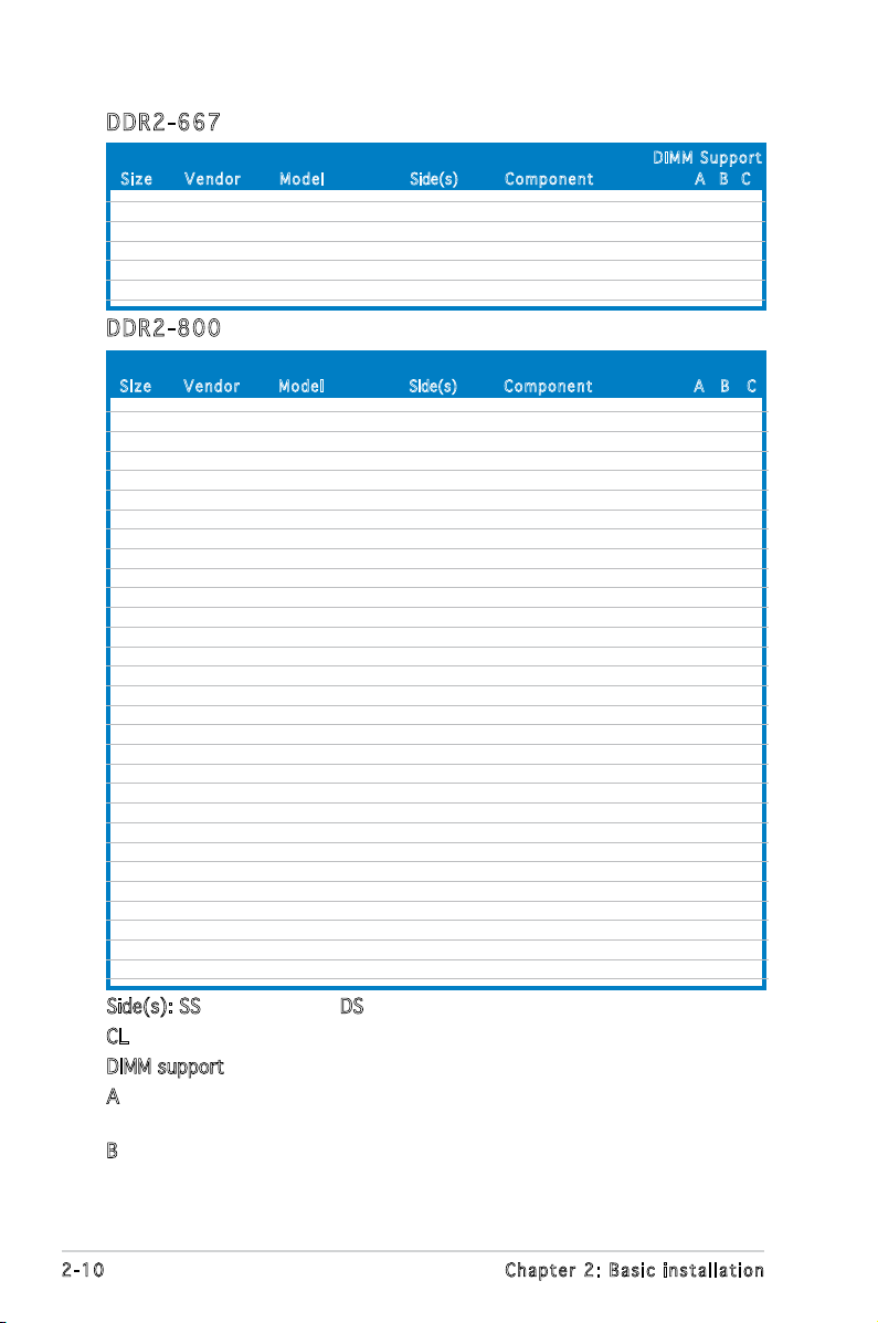
DDR 2 -66 7
Siz e Ve n d o r Mod e l Side(s) C o m ponen t A B C
512MB Transcend J12Q3AB-6 SS JM367Q643A-6 V V V
1024MB Transcend J12Q3AB-6 DS JM388Q643A-6
512MB Super Talent Heat-Sink Package SS T6UA512C5 V
1024MB Super Talent Heat-Sink Package DS T6UB1GC5 V V
512MB SMART G64M8XB3ITIX4TUE SS TB3D2667C58S V V
512MB SMART G64M8XB3ITIX4TUE DS TB4D2667C58D V V V
DIM M S uppor t
DDR 2 -80 0
Siz e Ve n d o r Mod e l Side(s) Com p o n ent A B C
512MB KINGSTON K4T51083QC SS KVR800D2N5/512 V V V
1024MB KINGSTON Heat-Sink Package DS KHX6400D2LL/1G
1024MB KINGSTON Heat-Sink Package SS KHX6400D2LLK2/1GN V V
256MB Qimonda HYB18T512160BF-25F SS HYS64T32000HU-25F-B V V V
512MB Qimonda HYB18T512800BF25F SS HYS64T64000HU-25F-B V V
1024MB Qimonda HYB18T512800BF25F DS HYS64T128020HU-25F-B V V V
512MB SAMSUNG EDD339XX SS M378T6553CZ3-CE7 V V
256MB SAMSUNG K4T51163QC-ZCE7 SS M378T3354CZ3-CE7 V V V
512MB SAMSUNG ZCE7K4T51083QC SS M378T6553CZ3-CE7 V V V
1024MB Hynix HY5PS12821CFP-S5 DS HYMP512U64CP8-S5 V V V
512MB MICRON 5JAIIZ9DQQ SS MT8HTF6464AY-80EA3 V V V
1024MB MICRON 5JAIIZ9DQQ DS MT16HTF12864AY-80EA3 V V V
512MB MICRON 5ZD22D9GKX SS MT8HTF6464AY-80ED4 V V V
1024MB MICRON 5ZD22D9GKX DS MT16HTF12864AY-80ED4 V V
512MB MICRON 6CD22D9GKX SS MT8HTF6464AY-80ED4 V V
1024MB MICRON 6CD22D9GKX DS MT16HTF12864AY-80ED4 V V V
1024MB CORSAIR Heat-Sink Package DS CM2X1024-6400C4 V V V
1024MB ELPIDA E1108AB-8E-E(ECC) SS EBE10EE8ABFA-8E-E V V V
2048MB ELPIDA E1108AB-8E-E(ECC) DS EBE21EE8ABFA-8E-E V V
512MB Crucial Heat-Sink Package SS BL6464AA804.8FD
512MB Crucial Heat-Sink Package SS BL6464AA804.8FD3 V V V
1024MB Crucial Heat-Sink Package DS BL12864AA804.16FD V
1024MB Crucial Heat-Sink Package DS BL12864AL804.16FD3 V V V
1024MB Crucial Heat-Sink Package DS BL12864AA804.16FD3 V V V
512MB Apacer Heat-Sink Package DS AHU512E800C5K1C V
1024MB Apacer Heat-Sink Package DS AHU01GE800C5K1C V V V
512MB Transcend K4T51083QC SS TS64MLQ64V8J V V V
1024MB Transcend K4T51083QC DS TS128MLQ64V8J V V V
512MB KINGMAX KKEA88B4LZUG-25DF SS KLDC28F-A8KB5
1024MB KINGMAX KKEA88B4LZUG-25DF DS KLDD48F-A8KB5 V V V
Side(s): SS - Single-sided DS - Double-sided
CL: CAS Latency
DIMM support:
A - Supports one module inserted into either slot, in Single-channel
memory conguration.
B - Supports one pair of modules inserted into both slots as one pair
of Dual-channel memory conguration.
2-10 Chapter 2: Basic installation
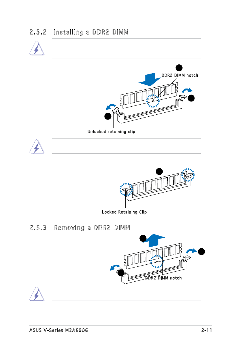
2.5 .2 Ins ta ll ing a D DR2 D IM M
Make sure to unplug the power supply before adding or removing DIMMs
or other system components. Failure to do so may cause severe damage
to both the motherboard and the components.
1. Unlock a DDR2 DIMM
socket by pressing the
retaining clips outward.
2. Align a DIMM on the socket
such that the notch on the
DIMM matches the break
on the socket.
1
Unl o c k ed re t a i ning c l i p
A DDR2 DIMM is keyed with a notch so that it ts in only one direction.
DO NOT force a DIMM into a socket to avoid damaging the DIMM.
3. Firmly insert the DIMM into the
socket until the retaining clips
snap back in place and the DIMM
is properly seated.
Loc k e d Reta i n i ng Cl i p
2.5 .3 Rem ov in g a D DR 2 D IM M
Follow these steps to remove a DIMM.
2
DDR 2 D IMM n o t c h
1
3
2
1. Simultaneously press the
retaining clips outward to
unlock the DIMM.
1
Support the DIMM lightly with your ngers when pressing the retaining
clips. The DIMM might get damaged when it ips out with extra force.
2. Remove the DIMM from the socket.
1
DDR 2 D IMM n o t c h
2-11ASUS V-Series M2A690G
2.6 Expansion slots
In the future, you may need to install expansion cards. The following
sub-sections describe the slots and the expansion cards that they support.
Make sure to unplug the power cord before adding or removing
expansion cards. Failure to do so may cause you physical injury and
damage motherboard components.
PCI Express Graphics Slot supports most of the ATi® and NVDIA® graphics
cards, except some ATi® graphics cards of old version, such as ATi®
X300, X550, X700, and X800 series.
2.6 .1 Ins ta ll ing a n ex p an si on ca rd
To install an expansion card:
1. Before installing the expansion card, read the documentation that
came with it and make the necessary hardware settings for the card.
2. Remove the system unit cover (if your motherboard is already
installed in a chassis).
3. Remove the bracket opposite the slot that you intend to use. Keep
the screw for later use.
4. Align the card connector with the slot and press rmly until the card is
completely seated on the slot.
5. Secure the card to the chassis with the screw you removed earlier.
6. Replace the system cover.
2.6 .2 Con fi gu rin g an e x pa ns io n c ar d
After installing the expansion card, congure it by adjusting the software
settings.
1. Turn on the system and change the necessary BIOS settings, if any.
See Chapter 5 for information on BIOS setup.
2. Assign an IRQ to the card. Refer to the tables on the next page.
3. Install the software drivers for the expansion card.
2-12 Chapter 2: Basic installation
 Loading...