

Asus KFN5-Q, KFN5-SAS User Manual

KFN5-Q
Series
KFN5-Q
KFN5-Q/SAS
KFN5-Q/1U
Motherboard
E292 4
Firs t E diti o n V1
Janu a r y 200 7
Copyright © 2007 ASUSTeK COMPUTER INC. All Rights Reserved.
No part of this manual, including the products and software described in it, may be reproduced,
transmitted, transcribed, stored in a retrieval system, or translated into any language in any form
or by any means, except documentation kept by the purchaser for backup purposes, without the
express written permission of ASUSTeK COMPUTER INC. (“ASUS”).
Product warranty or service will not be extended if: (1) the product is repaired, modied or
altered, unless such repair, modication of alteration is authorized in writing by ASUS; or (2) the
serial number of the product is defaced or missing.
ASUS PROVIDES THIS MANUAL “AS IS” WITHOUT WARRANTY OF ANY KIND, EITHER EXPRESS
OR IMPLIED, INCLUDING BUT NOT LIMITED TO THE IMPLIED WARRANTIES OR CONDITIONS OF
MERCHANTABILITY OR FITNESS FOR A PARTICULAR PURPOSE. IN NO EVENT SHALL ASUS,
ITS DIRECTORS, OFFICERS, EMPLOYEES OR AGENTS BE LIABLE FOR ANY INDIRECT, SPECIAL,
INCIDENTAL, OR CONSEQUENTIAL DAMAGES (INCLUDING DAMAGES FOR LOSS OF PROFITS, LOSS
OF BUSINESS, LOSS OF USE OR DATA, INTERRUPTION OF BUSINESS AND THE LIKE), EVEN IF ASUS
HAS BEEN ADVISED OF THE POSSIBILITY OF SUCH DAMAGES ARISING FROM ANY DEFECT OR
ERROR IN THIS MANUAL OR PRODUCT.
SPECIFICATIONS AND INFORMATION CONTAINED IN THIS MANUAL ARE FURNISHED FOR
INFORMATIONAL USE ONLY, AND ARE SUBJECT TO CHANGE AT ANY TIME WITHOUT NOTICE, AND
SHOULD NOT BE CONSTRUED AS A COMMITMENT BY ASUS. ASUS ASSUMES NO RESPONSIBILITY
OR LIABILITY FOR ANY ERRORS OR INACCURACIES THAT MAY APPEAR IN THIS MANUAL,
INCLUDING THE PRODUCTS AND SOFTWARE DESCRIBED IN IT.
Products and corporate names appearing in this manual may or may not be registered
trademarks or copyrights of their respective companies, and are used only for identication or
explanation and to the owners’ benet, without intent to infringe.
ii
Contents
Notices ................................................................................................vii
Safety information .............................................................................viii
About this guide .................................................................................. ix
Typography .......................................................................................... x
KFN5-Q Series specications summary ............................................... xi
Cha p te r 1: Pr o duc t i n tro d uc t ion
1.1 Welcome! .............................................................................. 1-1
1.2 Package contents .................................................................
1.3 Serial number label
1.4 Special features ....................................................................
1.4.1 Product highlights ...................................................
1.4.2 Innovative ASUS features .......................................
Cha p te r 2: Ha r dwa r e i nfo r ma t ion
2.1 Before you proceed .............................................................. 2-1
Onboard LEDs ....................................................................... 2-1
2.2 Motherboard overview ..........................................................
2.2.1 Placement direction ................................................
2.2.2 Screw holes .............................................................
2.2.3 Motherboard layout ................................................
2.2.4 Layout Contents .....................................................
2.3 Central Processing Unit (CPU) ..............................................
2.3.1 Installing the CPU ....................................................
2.3.2 Installing the CPU heatsink and fan .......................
2.4 System memory ..................................................................
2.4.1 Overview ...............................................................
2.4.2 Memory Congurations .........................................
2.4.3 Installing a DIMM ...................................................
2.4.4 Removing a DIMM ..................................................
2.5 Expansion slots ...................................................................
2.5.1 Installing an expansion card ..................................
2.5.2 Conguring an expansion card ..............................
2.5.3 Interrupt assignments ...........................................
2.5.4 PCI/PCI-X slots ......................................................
2.5.5 PCI Express x16 slot (x8 link) ...............................
................................................................ 1-1
1-1
1-2
1-2
1-4
2-3
2-3
2-3
2-4
2-7
2-9
2-9
2-12
2-14
2-14
2-15
2-17
2-17
2-18
2-18
2-18
2-19
2-19
2-21
iii
Contents
2.5.6 PCI Express x8 slot (x8 link) ................................. 2-21
2.5.7 ZCR slot .................................................................
2.5.8 HyperTransport (HTX) slot ...................................
2.5.9 DDR SO-DIMM slot .................................................
2.6 Jumpers ..............................................................................
2.7 Switches .............................................................................
2.8 Connectors .........................................................................
2.8.1 Rear panel connectors ..........................................
2.8.2 Internal connectors ...............................................
Cha p te r 3: Po w eri n g u p
3.1 Starting up for the rst time ................................................ 3-1
3.2 Powering off the computer ...................................................
3.2.1 Using the OS shut down function ...........................
3.2.2 Using the dual function power switch .....................
Cha p te r 4: BI O S s e tu p
4.1 Managing and updating your BIOS ........................................ 4-1
4.1.1 Creating a bootable oppy disk ..............................
4.1.2 AFUDOS utility ........................................................
4.1.3 ASUS CrashFree BIOS 2 utility ................................
4.1.4 ASUS Update utility ................................................
4.2 BIOS setup program ..............................................................
4.2.1 BIOS menu screen ...................................................
4.2.2 Menu bar .................................................................
4.2.3 Navigation keys .......................................................
4.2.4 Menu items .............................................................
4.2.5 Sub-menu items ......................................................
4.2.6 Conguration elds .................................................
4.2.7 Pop-up window ........................................................
4.2.8 Scroll bar .................................................................
4.2.9 General help ............................................................
4.3 Main menu ...........................................................................
4.3.1 System Time ........................................................
4.3.2 System Date ........................................................
4.3.3 Floppy A ...............................................................
2-22
2-22
2-23
2-24
2-29
2-31
2-31
2-32
3-2
3-2
3-2
4-1
4-2
4-4
4-6
4-7
4-8
4-8
4-8
4-9
4-9
4-9
4-9
4-9
4-9
4-10
4-10
4-10
4-10
iv
Contents
4.3.4 IDE Conguration .................................................. 4-11
4.3.5 System Information
4.4 Advanced menu ..................................................................
4.4.1 CPU Conguration .................................................
4.4.2 Chipset ..................................................................
4.4.3 PCI PnP ..................................................................
4.4.4 USB Conguration .................................................
4.4.5 ACPI Conguration ...............................................
4.4.6 Peripheral Devices Conguration ..........................
4.4.7 Power On Conguration ........................................
4.4.8 Hardware Monitor ..................................................
4.4.9 Trusted Computing ...............................................
4.5 Server Menu ........................................................................
4.5.1 Remote Access Conguration ...............................
4.5.2 ASUSLog Conguration ........................................
4.6 Security menu .....................................................................
4.7 Boot menu ..........................................................................
4.7.1 Boot Settings Conguration .................................
4.7.2 Boot Device Priority ..............................................
4.7.3 Remote Drives .......................................................
4.8 Exit menu ............................................................................
............................................... 4-13
4-14
4-14
4-15
4-20
4-22
4-23
4-24
4-25
4-27
4-28
4-29
4-29
4-31
4-31
4-32
4-33
4-34
4-34
4-35
Cha p te r 5: RA I D c o nf i gur a ti o n
5.1 Setting up RAID .................................................................... 5-1
5.1.1 RAID denitions .......................................................
5.1.2 Installing hard disk drives ........................................
5.1.3 RAID conguration utility ........................................
®
5.2 NVIDIA
5.2.1 Setting the BIOS RAID items ...................................
5.3 LSI Logic MPT Setup Utility
(
5.3.1 Integrated Mirroring ................................................
5.3.2 Integrated Mirroring Enhanced ...............................
5.3.3 Integrated Striping (IS) Volume ............................
RAID congurations................................................. 5-3
For KFN5-Q/SAS model only
) ............................................. 5-4
5-1
5-2
5-2
5-3
5-4
5-9
5-11
v
Contents
5.3.4 Managing arrays ....................................................5-14
5.3.5 Selecting a boot disk ............................................
5.3.6 Global_Properties ..................................................
Cha p te r 6: Dr i ver in s tal l at i on
6.1 RAID driver installation .......................................................... 6-1
6.1.1 Creating a RAID driver disk .....................................
®
Windows
Red Hat
Enterprise Server ....................................................
6.1.2 Installing the RAID controller driver ........................
Windows
Red Hat
SuSE Linux ............................................................
®
6.2 NVIDIA
nForce 3600 Professional
(MCP55) driver installation .................................................
6.2.1 Windows
6.3 LAN driver installation ........................................................
6.3.1 Windows
6.3.2 Red Hat
6.4 VGA driver installation ........................................................
6.4.1 Windows
6.5 AMD processor driver installation .......................................
6.5.1 Windows XP 32bit/64bit and
2003 Server 32bit/64bit .....................................
6.6 Management applications and utilites installation ..............
6.5.1 Running the support CD ........................................
6.5.2 Drivers menu .........................................................
6.5.3 Management Software menu ................................
6.5.4 Utilities menu ........................................................
6.5.5 Contact information ..............................................
2000/2003 Server ................................ 6-2
®
Enterprise Linux/SUSE
®
2000/2003 Server OS ........................... 6-4
®
Enterprise Linux ....................................... 6-9
®
2000/2003 Server .............................. 6-14
®
2000/2003 Server .............................. 6-17
®
Enterprise Linux ..................................... 6-18
®
2000/2003 Server ............................. 6-20
5-20
5-21
6-1
6-3
6-4
6-12
6-14
6-17
6-20
6-23
6-23
6-26
6-26
6-26
6-27
6-27
6-27
App e nd i x: R ef e ren c e I nfo r ma t ion
A.1 KFN5-Q model block diagram ............................................... A-1
A.2 KFN5-Q/SAS model block diagram .......................................
A.3 KFN5-Q/1U model block diagram .........................................
vi
A-2
A-3
Notices
Fed er al Co mm un ica ti on s C om mi ssi on S tat em en t
This device complies with Part 15 of the FCC Rules. Operation is subject to
the following two conditions:
•
This device may not cause harmful interference, and
•
This device must accept any interference received including
interference that may cause undesired operation.
This equipment has been tested and found to comply with the limits for a
Class B digital device, pursuant to Part 15 of the FCC Rules. These limits
are designed to provide reasonable protection against harmful interference
in a residential installation. This equipment generates, uses and can radiate
radio frequency energy and, if not installed and used in accordance with
manufacturer’s instructions, may cause harmful interference to radio
communications. However, there is no guarantee that interference will
not occur in a particular installation. If this equipment does cause harmful
interference to radio or television reception, which can be determined by
turning the equipment off and on, the user is encouraged to try to correct
the interference by one or more of the following measures:
•
Reorient or relocate the receiving antenna.
•
Increase the separation between the equipment and receiver.
•
Connect the equipment to an outlet on a circuit different from that to
which the receiver is connected.
•
Consult the dealer or an experienced radio/TV technician for help.
The use of shielded cables for connection of the monitor to the graphics
card is required to assure compliance with FCC regulations. Changes
or modications to this unit not expressly approved by the party
responsible for compliance could void the user’s authority to operate
this equipment.
Can ad ia n D ep ar tme nt o f C om mu nic at io ns St at eme nt
This digital apparatus does not exceed the Class B limits for radio noise
emissions from digital apparatus set out in the Radio Interference
Regulations of the Canadian Department of Communications.
This class B digital apparatus complies with Canadian
ICES-003.
vii
Safety information
Ele ct ri cal s af ety
•
To prevent electrical shock hazard, disconnect the power cable from
the electrical outlet before relocating the system.
•
When adding or removing devices to or from the system, ensure that
the power cables for the devices are unplugged before the signal
cables are connected. If possible, disconnect all power cables from the
existing system before you add a device.
•
Before connecting or removing signal cables from the motherboard,
ensure that all power cables are unplugged.
•
Seek professional assistance before using an adapter or extension
cord. These devices could interrupt the grounding circuit.
•
Make sure that your power supply is set to the correct voltage in your
area. If you are not sure about the voltage of the electrical outlet you
are using, contact your local power company.
•
If the power supply is broken, do not try to fix it by yourself. Contact
a qualified service technician or your retailer.
Ope ra ti on sa fe ty
•
Before installing the motherboard and adding devices on it, carefully
read all the manuals that came with the package.
•
Before using the product, make sure all cables are correctly connected
and the power cables are not damaged. If you detect any damage,
contact your dealer immediately.
•
To avoid short circuits, keep paper clips, screws, and staples away from
connectors, slots, sockets and circuitry.
•
Avoid dust, humidity, and temperature extremes. Do not place the
product in any area where it may become wet.
•
Place the product on a stable surface.
•
If you encounter technical problems with the product, contact a
qualified service technician or your retailer.
viii
The symbol of the crossed out wheeled bin indicates that the product
(electrical and electronic equipment) should not be placed in municipal
waste. Check local regulations for disposal of electronic products.
About this guide
This user guide contains the information you need when installing and
conguring the motherboard.
How t hi s g ui de is o rg ani ze d
This manual contains the following parts:
• Chap t e r 1: P r o duct i n trod u c t ion
This chapter describes the features of the motherboard and the new
technology it supports.
• Chap t e r 2: H a r dwar e i nfor m a t ion
This chapter lists the hardware setup procedures that you have to
perform when installing system components. It includes description of
the switches, jumpers, and connectors on the motherboard.
• Chap t e r 3: P o w erin g u p
This chapter describes the power up sequence, the vocal POST
messages, and ways of shutting down the system.
• Chap t e r 4: B I O S se t u p
Tells how to change system settings through the BIOS Setup menus.
Detailed descriptions of the BIOS parameters are also provided.
• Chap t e r 5: R A I D co n f i gura t i o n
Provides information on RAID congurations for this motherboard.
• Chap t e r 6: D r i ver i n s tall a t i on
This chapter provides information on RAID and LAN driver installation
for this motherboard.
• Appe n d i x: R e f e renc e i nfor m a t ion
This appendix includes additional information that you may refer to
when conguring the motherboard.
Whe re t o f in d mor e in for ma ti on
Refer to the following sources for additional information and for product
and software updates.
1. ASUS w e bsit e s
The ASUS website provides updated information on ASUS hardware
and software products. Refer to the ASUS contact information.
2. Opti o n a l do c u m enta t i o n
Your product package may include optional documentation, such as
warranty yers, that may have been added by your dealer. These
documents are not part of the standard package.
ix
Con ve nt ion s us ed in t his g ui de
To make sure that you perform certain tasks properly, take note of the
following symbols used throughout this manual.
DANGER/WARNING: Information to prevent injury to yourself
when trying to complete a task.
CAUTION: Information to prevent damage to the components
when trying to complete a task.
IMPORTANT: Instructions that you MUST follow to complete a
task.
NOTE: Tips and additional information to help you complete a
task.
Typography
Bold text Indicates a menu or an item to select.
Italics
Used to emphasize a word or a phrase.
<Key> Keys enclosed in the less-than and
greater-than sign means that you must
press the enclosed key.
Example: <Enter> means that you must
press the Enter or Return key.
<Key1> + <Key2> + <Key3> If you must press two or more keys
simultaneously, the key names are linked
with a plus sign (+).
Example: <Ctrl> + <Alt> +<Del>
Command Means that you must type the command
exactly as shown, then supply the
required item or value enclosed in
brackets.
Example: At the DOS prompt, type the
command line:
x
format A:/S
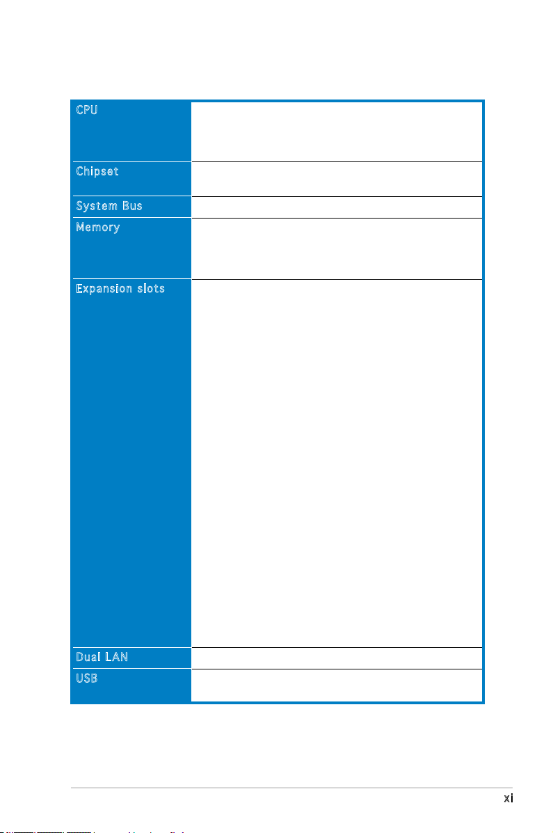
KFN5-Q Series specications summary
CPU
Chipset
System Bus
Memory
Expansion slots
Dual LAN
USB
Quad Socket F (1207) for next generation AMD®
Opteron™ 8000 Series processor
Supports AMD 64 architecture that enables simultaneous
32-bit and 64-bit architecture
NVIDIA® nForce Professional 3600 (MCP55 Pro)
Intel® 6702PXH (I/O Bridge)
1000 MHz HyperTransport Link
Dual-channel memory architecture
16 x 240-pin DIMM sockets support registered
ECC DDR2 400/533/667 memory modules
Supports 256 MB up to 64 GB system memory
KFN5-Q model:
1 x PCI Express™ x16 slot (x8 Link)
1 x PCI Express™ x8 slot (x8 Link)
1 x HyperTransport (HTX) connectors
1 x PCI 32bit/33MHz (5V) slot
2 x PCI-X 64bit/133/100MHz (3.3V) slots
1 x DDR2 SO-DIMM socket for ASUS Server Management
Board 3 Series (ASMB3)
KFN5-Q/SAS model:
1 x PCI Express™ x16 slot (x8 Link)
1 x PCI Express™ x8 slot (x8 Link)
1 x HyperTransport (HTX) connectors
1 x PCI 32bit/33MHz (5V) slot
1 x PCI-X 64bit/100MHz (3.3V) slot for optional Zero
Channel RAID (ZCR) card (green)
1 x PCI-X 64bit/100MHz (3.3V) slots
1 x DDR2 SO-DIMM socket for ASUS Server Management
Board 3 Series (ASMB3)
KFN5-Q/1U model:
1 x PCI Express™ x16 slot (x8 Link)
1 x PCI Express™ x8 slot (x8 Link)
1 x HyperTransport (HTX) connectors
1 x PCI 32bit/33MHz (5V) slot
1 x DDR2 SO-DIMM socket for ASUS Server Management
Board 3 Series (ASMB3)
Dual Onboard BCM5721 Gigabit PCI-E LAN controllers
2 x USB 2.0 ports (on the rear panel)
2 x USB 2.0 connector (on board)
(continued on the next page)
xi
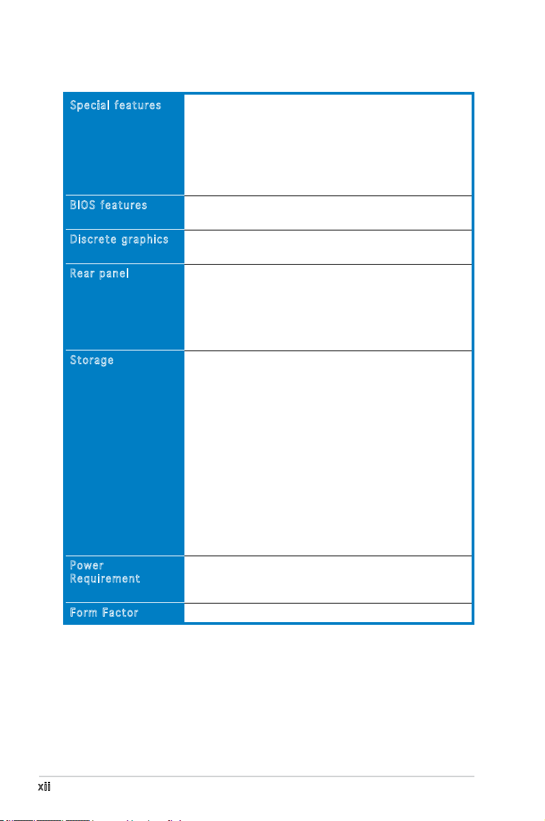
KFN5-Q Series specications summary
Special features
BIOS features
Discrete graphics
Rear panel
Storage
Power
Requirement
Form Factor
ASUS Smart Fan Technology
ASUS Smart Fan2 Technology
ASUS CrashFree BIOS 2
ASUS MyLogo2
ASUS CPU Overheating Protection (C.O.P)
BIOS Recovery
CPU Warning LED
AMI BIOS, 8 MB LPC, Green, PnP, DMI, SMBIOS 2.3,
ACPI 2.0a, Trend Chip Away Virus (TCAV)
ATI ES1000 PCI display controller
Supports 32MB display memory
1 x Serial port
1 x VGA port
2 x USB 2.0 ports
1 x PS/2 keyboard port
1 x PS/2 mouse port
2 x RJ-45 ports
®
NVIDIA
nForce 3600 Professional supports:
- 1 x IDE connector for up to two Ultra DMA
33/66/100/133 devices
- 6 x Serial ATA 3.0 Gb/s connectors support six
Serial ATA devices
- RAID 0, RAID 1, RAID 10, RAID 5, and JBOD
supported across Serial ATA drives via the onboard
NVIDIA
®
MediaShield™ Utility
KFN5-Q/SAS model only:
LSI1068 PCI-X SAS controller supports:
- 2 x Serial Attached SCSI (SAS) channels (each channel
supports four HDDs) with RAID 0, RAID 1, and RAID 1E
congurations
- Zero-Channel RAID card (optional)
SSI power supply (with 24-pin and 2 x 8-pin 12 V plugs)
EPS 12V 2.0 compliant
Minimum 800W power is recommended
Full-AT form factor: 16” x 13” (40.6 cm x 33.0 cm)
xii
(continued on the next page)
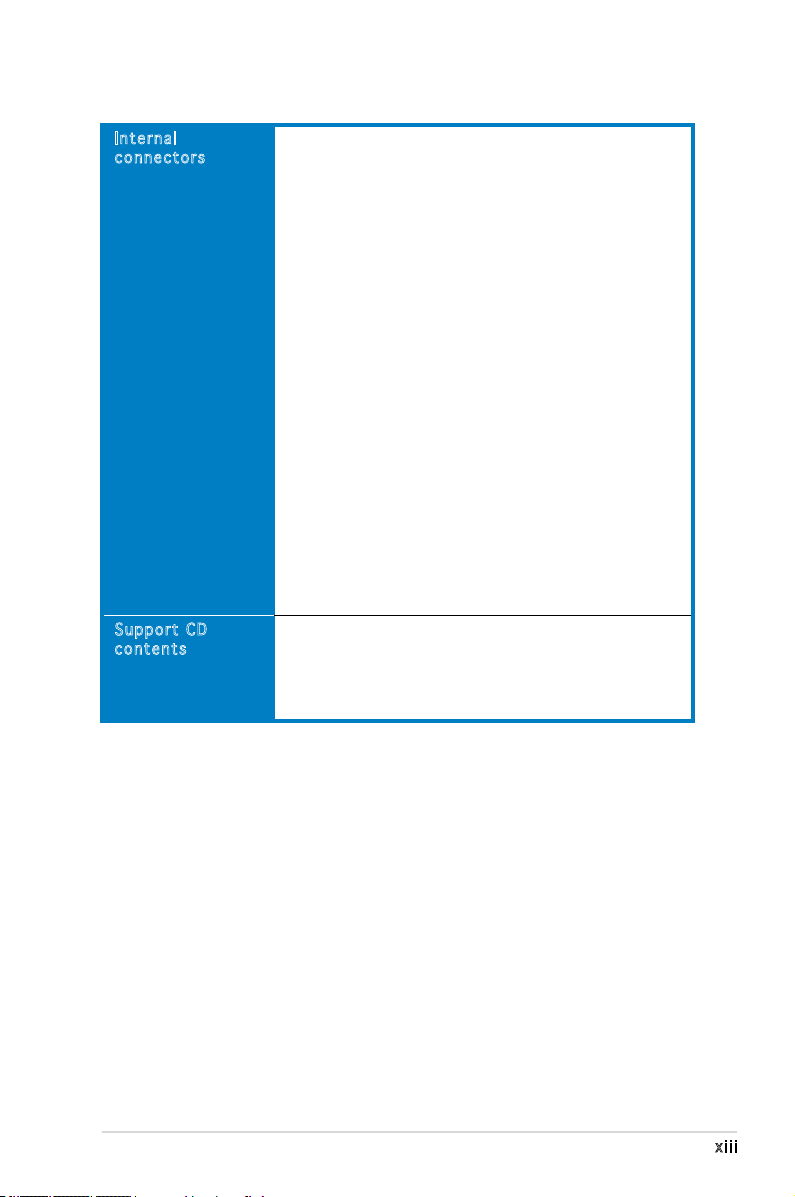
KFN5-Q Series specications summary
Internal
connectors
Support CD
contents
1 x Floppy disk drive connector (34-1 pin FLOPPY1)
1 x IDE connector (40-1 pin PRI_IDE1)
6 x Serial ATA connectors (7-pin SATA1, SATA2,
SATA3, SATA4, SATA5, SATA6)
1 x Hard disk activity LED connector (4-pin HDLED1)
1 x USB connector (10-1 pin USB34)
1 x Serial port connector (10-1 pin COM2)
1 x Power supply SMBUS connector (5-pin PSUSMB1)
1 x Parallel port connector (26-1 pin LPT1)
1 x Backplane SMBUS connector (7-1 pin BPSMB1)
1 x Serial General Purpose Input/Output connector for
NVIDIA® MediaShield™ RAID SATA LED (8-1 pin SGPIO1)
1 x System panel connector (20-1pin PANEL1)
1 x System panel auxiliary connector (20-2 pin AUX_PANEL1)
1 x LPC connector for LPC debug (14-1 pin LPC1)
1 x TPM connector (20-1 pin TPM1)
SSI power connectors (24-pin ATXPWR1, 2x 8-pin ATX12V1,
ATX12V2)
CPU (x4), front (x6), and rear (x2) 4-pin fan connectors
(
KFN5-Q/SAS model only
2 x mini-SAS connectors support a total of eight (8)
devices
1 x SAS LSI1068 ports LED connector (18-1 pin
SASLED1)
Device drivers
ASUS Live Update utility
ASUS Server Web-based Management (ASWM)
NVIDIA Raid Utility
ASUS Flash Utility under DOS
)
*Specications are subject to change without notice.
xiii

This chapter describes the motherboard
features and the new technologies
it supports.
introduction
Product
1
Chapter summary
1
1.1 Welcome! .............................................................................. 1-1
1.2 Package contents .................................................................
1.3 Serial number label ..............................................................
1.4 Special features ....................................................................
1-1
1-1
1-2
ASUS KFN5-Q Series
1.1 Welcome!
Thank you for buying an ASUS® KFN5-Q Series motherboard!
The motherboard delivers a host of new features and latest technologies,
making it another standout in the long line of ASUS quality motherboards!
Before you start installing the motherboard, and hardware devices on it,
check the items in your package with the list below.
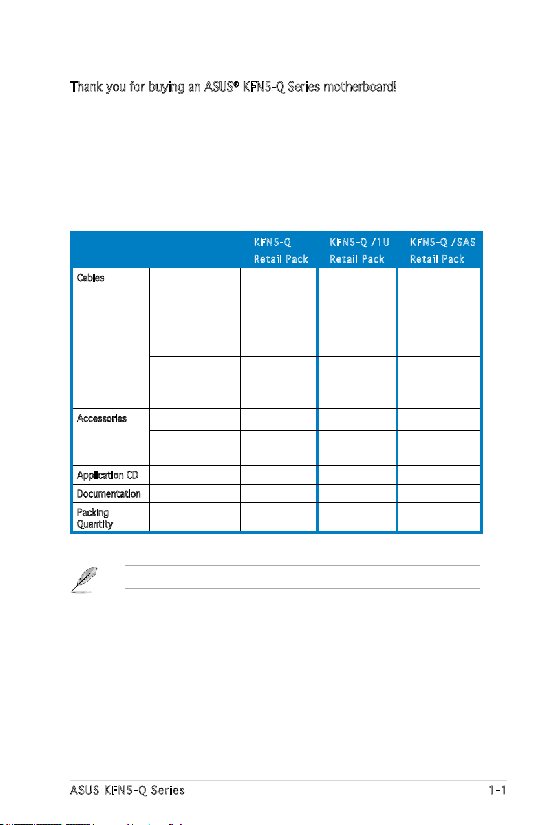
1.2 Package contents
Check your motherboard package for the following items.
KFN 5 - Q
Ret a i l Pack
Cables Serial ATA signal
cable
Serial ATA power
cable
SAS cable - - 2
2-in-1 Floppy/Ultra
ATA disk drive
cable set
Accessories I/O shield 1 1 1
Retention module
& screws
Application CD Support CD 1 1 1
Documentation User guide 1 1 1
Packing
Quantity
6 6 6
3 3 3
1 1 1
4 - 4
3 pieces per
carton
KFN 5 - Q /1U
Ret a i l Pack
3 pieces per
carton
KFN 5 - Q /SAS
Ret a i l Pack
3 pieces per
carton
If any of the above items is damaged or missing, contact your retailer.
ASUS KFN5-Q Series 1-1
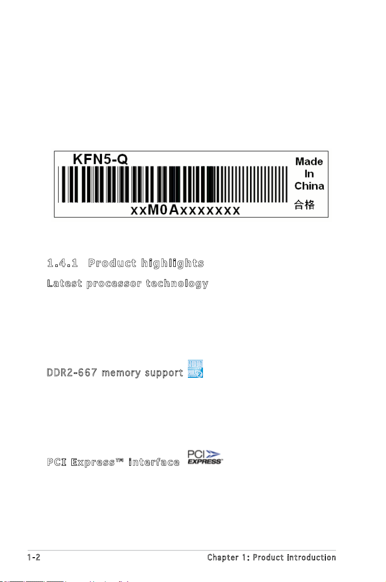
1.3 Serial number label
Before requesting support from the ASUS Technical Support team,
you must take note of the motherboard’s serial number containing 12
characters such as xxM0Axxxxxxx. See gure below.
With the correct serial number of the product, ASUS Technical Support
team members can then offer a quicker and satisfying solution to your
problems.
1.4 Special features
1. 4 .1 P r o du ct h i gh li g h t s
Lat e st pro c es s or t ec h n ol o gy
The motherboard comes with a 1207-pin surface mount Land Grid Array
(LGA) socket coded Socket F, designed for the next generation AMD
Opteron™ 8000 series processor. The motherboard with the new socket
supports registered DDR2-667/533/400 memory, delivering advanced
performance and ensuring reliable data protection.
DDR 2 -66 7 m e mor y s u ppo r t
The motherboard supports DDR2 memory which features data transfer
rates of up to 667 MHz to meet the higher bandwidth requirements of the
latest server applications. The dual-channel memory architecture doubles
the bandwidth of your system memory to boost system performance,
eliminating bottlenecks with peak bandwidths of up to 10.7 GB/s.
PCI Ex p res s ™ i nte r fa c e
The motherboard fully supports PCI Express, the latest I/O interconnect
technology that speeds up the PCI bus. PCI Express features point-to-point
serial interconnections between devices and allows higher clockspeeds by
carrying data in packets. This high speed interface is software compatible
with existing PCI or PCI-X specications.
1-2 Chapter 1: Product introduction
Hyp e rT r ans p or t (H T X)
HyperTransport (HTX) is an industry-standard interconnect that allows
direct peripheral-card to the system CPU communications, speeding
performance, and reducing latency. The HTX specication support up
to 6.4GB/s data transfer rate, and with 2 x 16-bit, double data rate
HyperTransport lnks working at 800MHz clock.
Ser i al Att a ch e d S C SI (SA S ) t ech n ol o g y s up p o rt
(
KFN 5 -Q / SA S on l y
SAS is the latest storage interface for enterprise-class storage devices.
Building on and improving the parallel SCSI foundation, SAS is the new
industry standard that includes Serial ATA interoperability, and is projected
to be the successor of the Ultra320 SCSI technology.
)
Zer o C h ann e l R AID (Z C R) s ol u tio n
(
KFN 5 -Q / SA S on l y
The motherboard comes with a ZCR socket for an optional Zero-Channel
RAID card, allowing RAID 0 (striping), RAID 1 (mirroring), RAID 0+1, and
RAID 5 congurations. The ZCR capability provides a cost-effective high-
performance and added reliability.
)
Gig a bi t LA N s o lut i on
The motherboard comes with dual Gigabit LAN controllers and ports to
provide a total solution for your networking needs. The onboard Broadcom®
BCM5721 Gigabit LAN controllers use the PCI Express interface and could
achieve network throughput close to Gigabit bandwidth.
Ser i al ATA II tec h no l ogy
The motherboard supports the Serial ATA II technology through the Serial
ATA interfaces controlled by the NVIDIA® chipset. The SATA specication
allows for thinner, more exible cables with lower pin count, reduced
voltage requirement, and up to 300 MB/s data transfer rate.
SAS RA I D s o lu t ion
(
KFN 5 -Q / SA S on l y
Onboard RAID controllers provide the motherboard with dual-RAID
functionality that allows you to select the best RAID solution using SAS or
Serial ATA devices.
The NVIDIA® MCP55 Pro allows JBOD, RAID0, RAID1, and RAID5 (Software)
congurations for six SATA connectors.
ASUS KFN5-Q Series 1-3
)
The LSIS AS1068 is an eight-port, 3.0 Gbit/s SAS/SATA controller that is
compliant with the Fusion-MPT™ architecture, and supports the Integrated
RAID™ solution.
USB 2. 0 te c hn o log y
The motherboard implements the Universal Serial Bus (USB) 2.0
specication, dramatically increasing the connection speed from the
12 Mbps bandwidth on USB 1.1 to a fast 480 Mbps on USB 2.0. USB 2.0 is
backward compatible with USB 1.1.
Tem p er a tur e , f an, an d vo l ta g e m o ni t ori n g
The CPU temperature is monitored by the ASIC (integrated in the Winbond
hardware monitor) to prevent overheating and damage. The system fan
rotations per minute (RPM) is monitored for timely failure detection. The
ASIC monitors the voltage levels to ensure stable supply of current for
critical components.
1. 4 .2 I n n ov at i v e A SU S f ea tu r e s
Cra s hF r ee B IO S 2
This feature allows you to restore the original BIOS data from the support
CD in case when the BIOS codes and data are corrupted. This protection
eliminates the need to buy a replacement ROM chip.
ASU S S m art Fa n te c hn o log y
The ASUS Smart Fan technology smartly adjusts the fan speeds according
to the system loading to ensure quiet, cool, and efcient operation.
ASU S M y Log o 2™
This new feature present in the motherboard allows you to personalize and
add style to your system with customizable boot logos.
1-4 Chapter 1: Product introduction

This chapter lists the hardware setup
procedures that you have to perform
when installing system components.
It includes description of the jumpers
and connectors on the motherboard.
information
Hardware
2

Chapter summary
2
2.1 Before you proceed .............................................................. 2-1
2.2 Motherboard overview ..........................................................
2.3 Central Processing Unit (CPU) ..............................................
2.4 System memory ..................................................................
2.5 Expansion slots ...................................................................
2.6 Jumpers ..............................................................................
2.7 Switches .............................................................................
2.7 Connectors .........................................................................
2-3
2-9
2-14
2-18
2-24
2-29
2-31
ASUS KFN5-Q Series
2.1 Before you proceed
KFN5-Q/SAS
KFN5-Q Series Onboard LED
Take note of the following precautions before you install the motherboard
components or change any motherboard settings.
• Make sure that your power supply unit (PSU) can provide at least
the minimum power required by your system. See “10. SSI power
connectors” on page 2-38 for details.
• Unplug the power cord from the wall socket before touching any
component.
• Use a grounded wrist strap, or touch a safely grounded object or
a metal object (such as the power supply case) before handling
components to avoid damaging them due to static electricity.
• Hold the components by the edges to avoid touching the ICs on
them.
• Whenever you uninstall any component, place it on a grounded
antistatic pad or in the bag that came with the component.
• Before you install or remove any component, ensure that the ATX
power supply is switched off or the power cord is detached from
the power supply. Failure to do so may cause severe damage to the
motherboard, peripherals, and/or components.
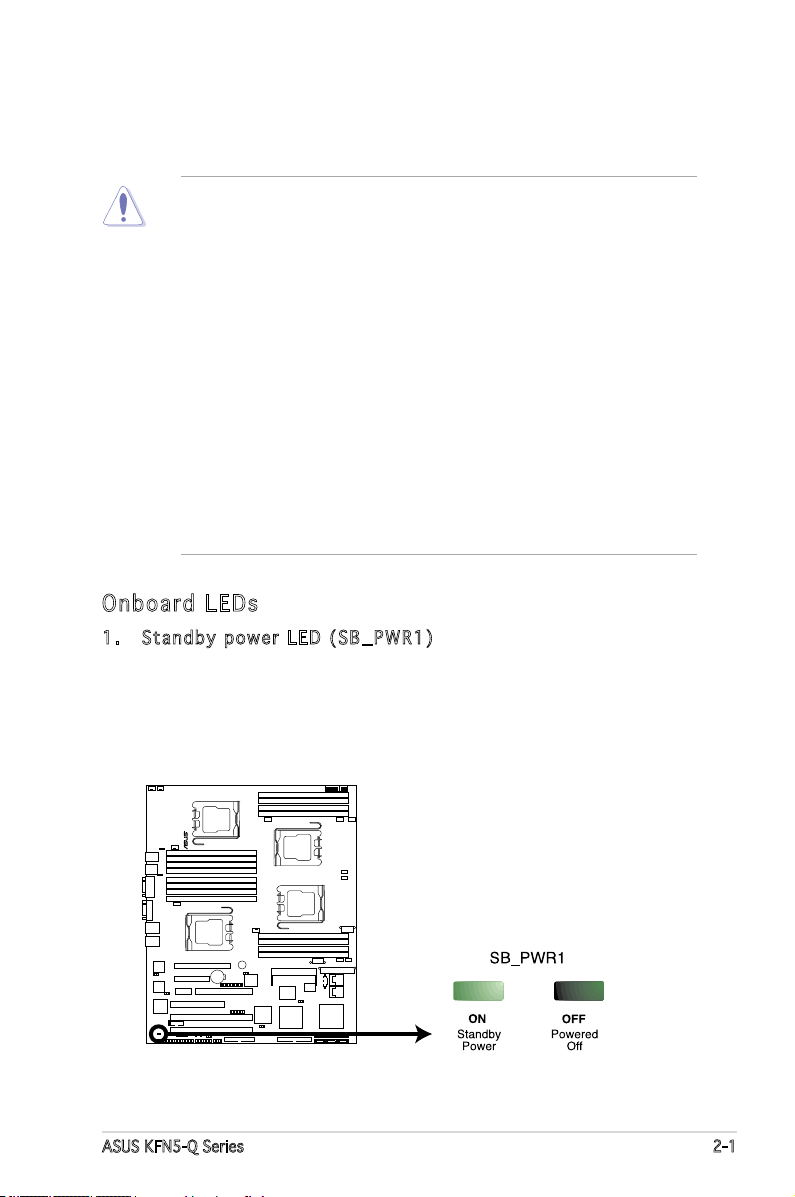
Onb oa rd LE Ds
1. Stan d b y pow e r LED ( S B _PWR 1 )
The motherboard comes with a green standby power LED that lights
up to indicate that the system is ON, in sleep mode, or in soft-off
mode. This is a reminder that you should shut down the system
and unplug the power cable before removing or plugging in any
motherboard component.
ASUS KFN5-Q Series 2-1
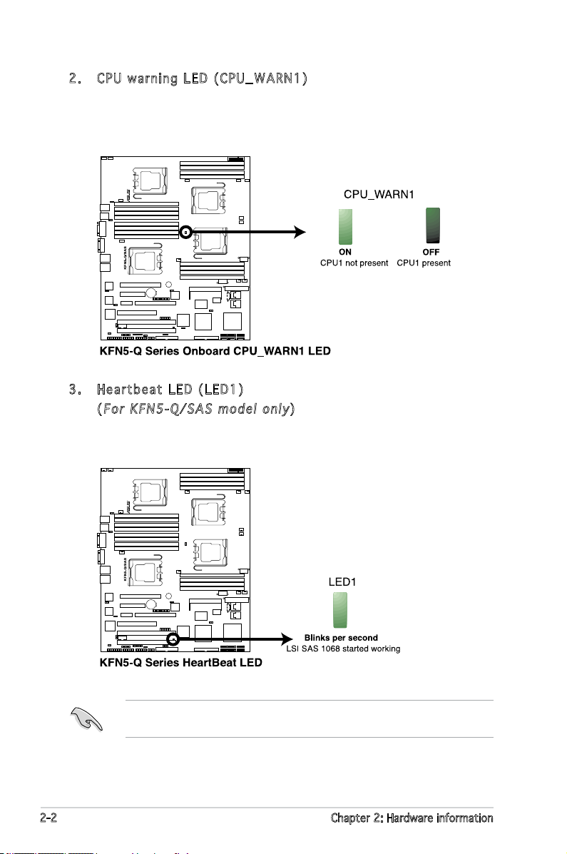
2. CPU w a r ning L E D (C P U _ WARN 1 )
The red CPU warning LED lights up to indicate that a processor is not
installed or the processor is not installed properly in CPU 1 socket.
3. Hear t b e at L E D (LED 1 )
(
For K F N 5-Q/ S A S mo d e l onl y
)
The green Heartbeat LED blinks per second to indicate that the LSI
SAS 1068 chipset has started working.
This LED is only for the KFN5-Q/SAS model, and it indicates if the LSI
SAS 1068 is working normally.
2-2 Chapter 2: Hardware information
2.2 Motherboard overview
KFN5-Q/SAS
Before you install the motherboard, study the conguration of your chassis
to ensure that the motherboard ts into it.
Make sure to unplug the power cord before installing or removing the
motherboard. Failure to do so can cause you physical injury and damage
motherboard components.
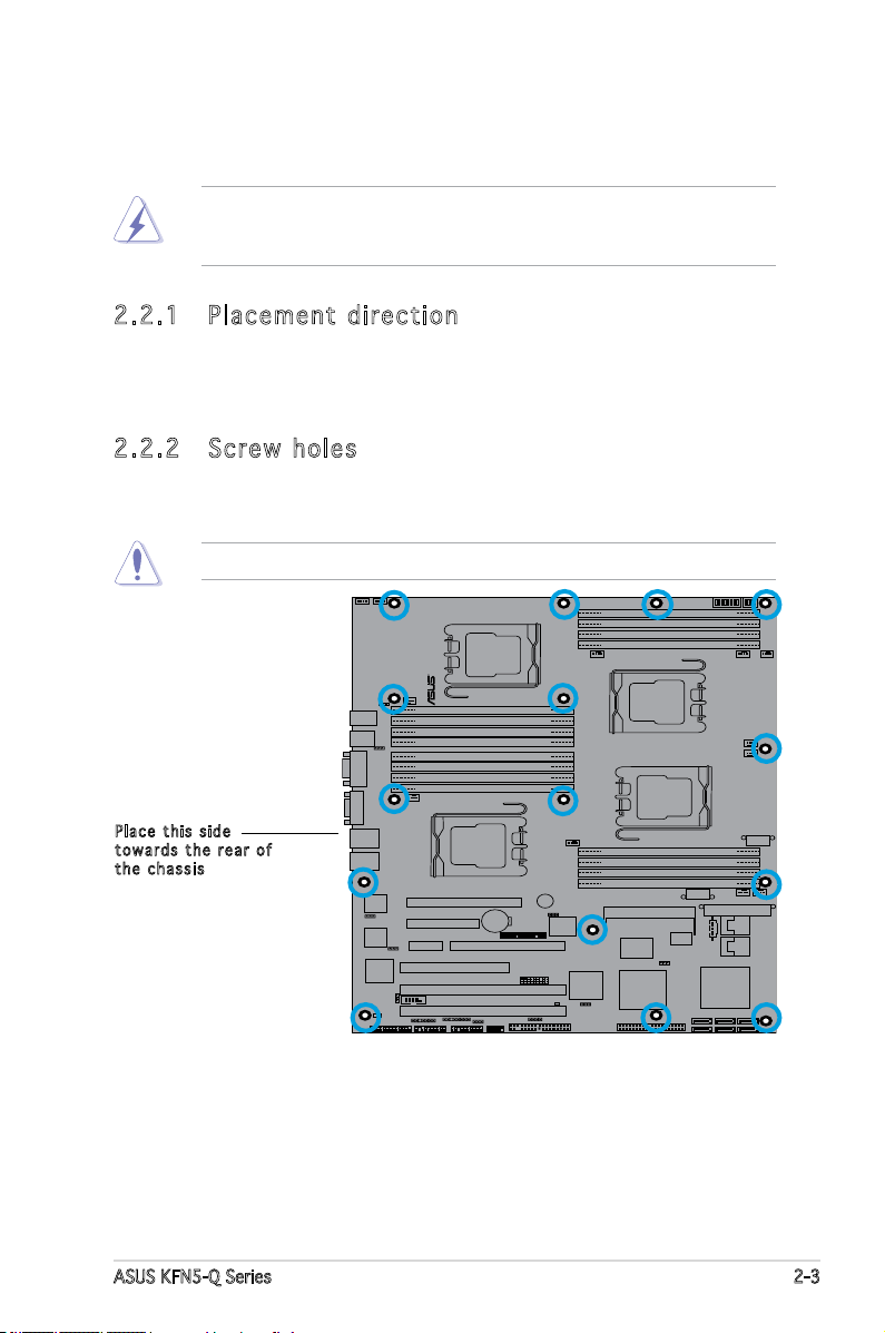
2.2 .1 Pla ce me nt di re cti on
When installing the motherboard, make sure that you place it into the
chassis in the correct orientation. The edge with external ports goes to the
rear part of the chassis as indicated in the image below.
2.2 .2 Scr ew h ole s
Place 15 screws into the holes indicated by circles to secure the
motherboard to the chassis.
Do not overtighten the screws! Doing so can damage the motherboard.
Pla c e this s i d e
tow a r d s the r e ar of
the c h assis
ASUS KFN5-Q Series 2-3
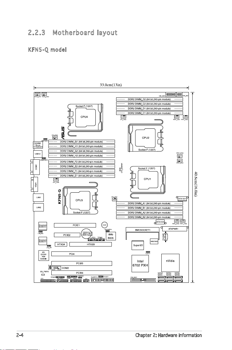
2.2 .3 Mot he rb oar d la you t
NFP-3600
KFN5 - Q mode l
2-4 Chapter 2: Hardware information
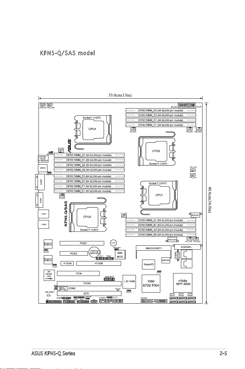
KFN5 - Q / SAS m o d el
ASUS KFN5-Q Series 2-5
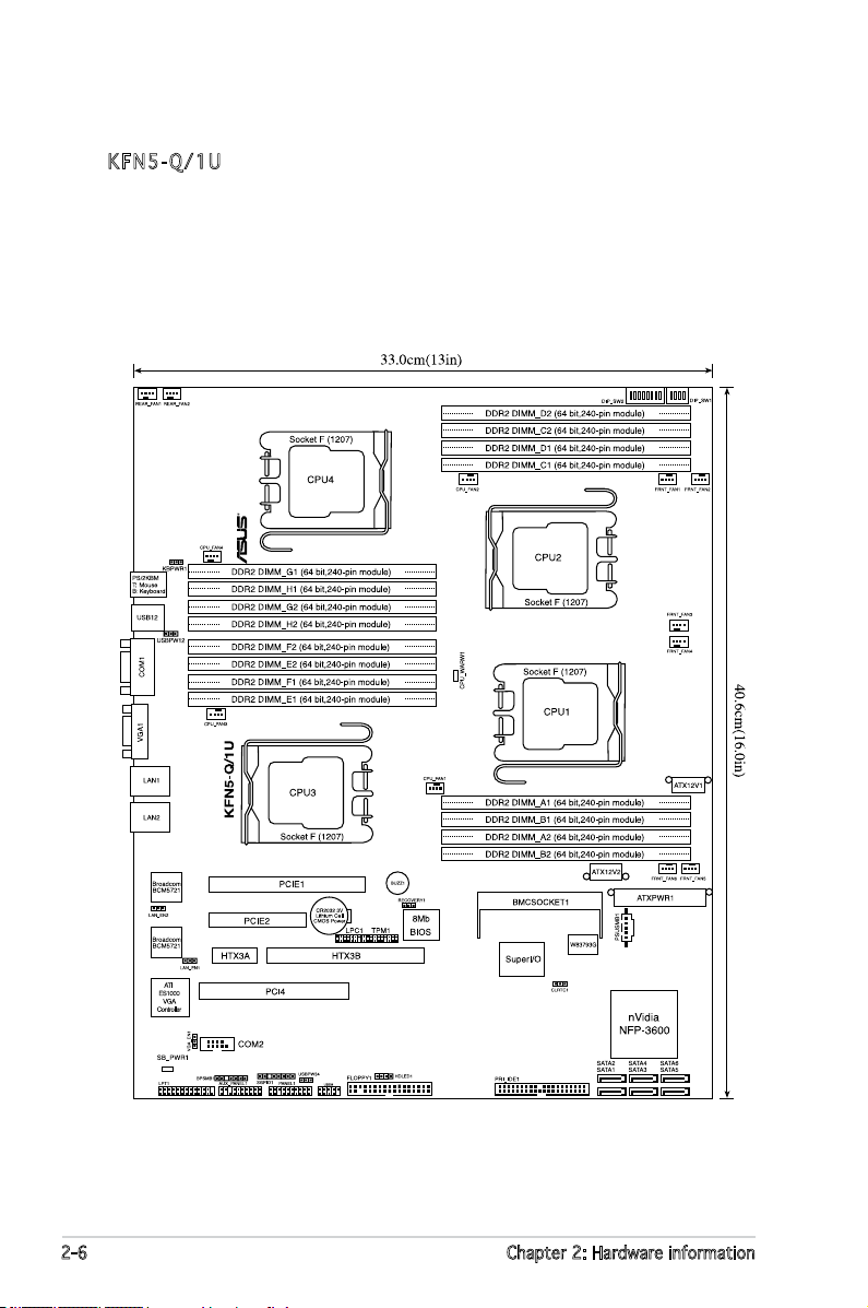
KFN5 - Q / 1U
2-6 Chapter 2: Hardware information
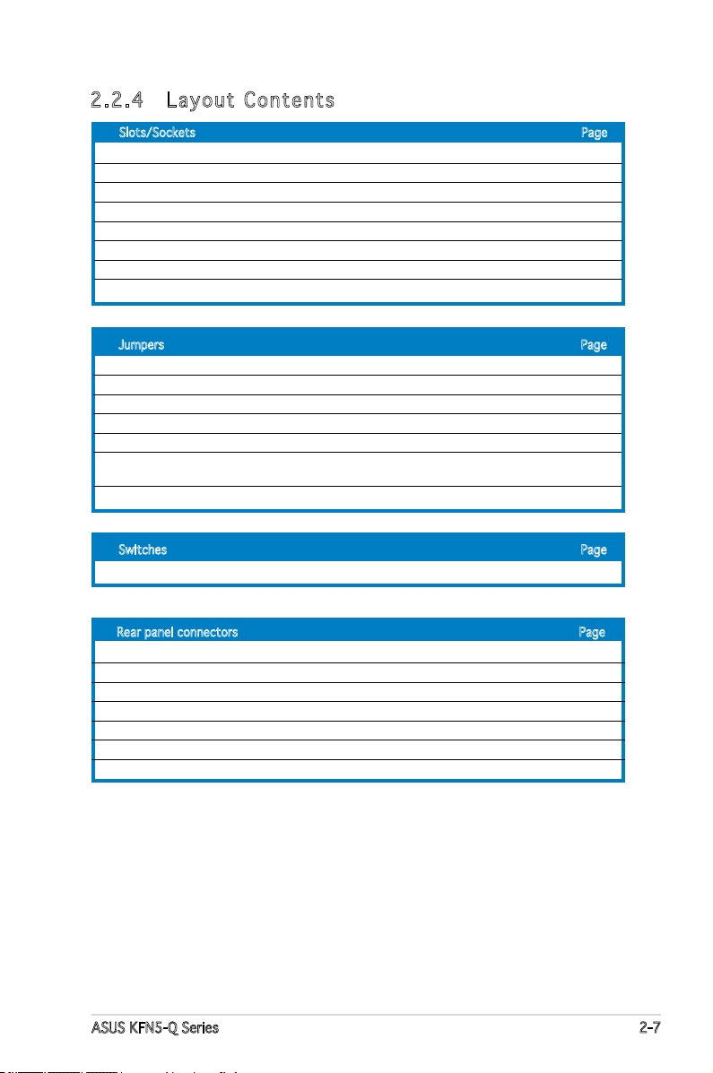
2.2 .4 Lay ou t Con te nt s
Slots/Sockets Page
1. CPU sockets 2-9
2. DDR2 DIMM sockets 2-14
3. PCI/PCI-X slots 2-19
4. PCI Express x16 slot (x8 link) 2-21
5. PCI Express x8 slot (x8 link) 2-21
6. ZCR slot (
7. HyperTransport (HTX) slot 2-22
8. DDR2 SO-DIMM slot 2-23
Jumpers Page
1. Clear RTC RAM (CLRTC1) 2-24
2. Keyboard power (3-pin KBPWR1) 2-25
3. Gigabit LAN controller setting (3-pin LAN_EN1, LAN_EN2) 2-25
4. BIOS Recovery (3-pin RECOVERY1) 2-26
5. VGA Graphics controller setting (3-pin VGA_EN1) 2-27
6. Onboard storage setting (3-pin SAS_EN1)
(
7. USB device wake-up (3-pin USBPW12, USBPW34) 2-28
Switches Page
1. DIP switch (DIP_SW1, DIP_SW2) 2-29
KFN5-Q/SAS model only
KFN5-Q/SAS model only
) 2-22
) 2-27
Rear panel connectors Page
1. PS/2 mouse port (green) 2-31
2. PS/2 keyboard port (purple) 2-31
3. USB 2.0 ports 1 and 2 2-31
4. Serial (COM 1) port 2-31
5. VGA port 2-31
6. LAN1 (RJ-45) port 2-31
7. LAN2 (RJ-45) port 2-31
ASUS KFN5-Q Series 2-7
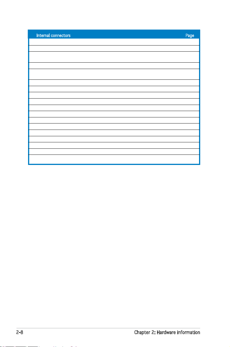
Internal connectors Page
1. Floppy disk drive connector (34-1 pin FLOPPY1) 2-32
2. IDE connectors (40-1 pin PRI_IDE1) 2-32
3. SAS LSI1068 ports LED connector (18-1 pin SASLED1)
(
KFN5-Q/SAS model only
4. Serial ATA connectors (4 SATA SATA1, SATA2, SATA3, SATA 4) 2-34
5. CPU, Front and Rear fan connectors
(4-pin CPU_FAN1/4, 3-pin FRNT_FAN1/6, REAR_FAN1/2) 2-34
6. Backpane SMBus connector (7-1 pin BPSMB1) 2-35
7. USB connector (10-1 pin USB34) 2-36
8. System panel auxiliary connector (20-2 pin AUX_PANEL1) 2-36
9. System panel connector (20-pin PANEL1) 2-37
10. SSI power connectors (24-pin ATXPWR1, 2x 8-pin ATX12V1, ATX12V2) 2-38
11. Serial port connector (10-1 pin COM2) 2-39
12. Power supply SMBus connector (5-pin PSUSMB1) 2-40
13. Hard disk activity LED connector (4-pin HDLED1) 2-40
14. Parallel port connector (26-1 pin LPT1) 2-41
15. Serial General Purpose Input/Output connector (8-1 pin SGPIO1) 2-41
16. TPM connector (20-1 pin TPM) 2-42
17. LPC debug card connector (14-pin LPC1) 2-42
18. Mini-SAS connectors (
) 2-33
KFN5-Q/SAS model only
) 2-43
2-8 Chapter 2: Hardware information

2.3 Central Processing Unit (CPU)
KFN5-Q/SAS
KFN5-Q Series
CPU Socket 1207
The motherboard comes with a surface mount Socket F designed for the
AMD® Opteron® CPU in the Land Grid Array (LGA) package.
•
Upon purchase of the motherboard, make sure that the PnP cap is
on the socket and the socket contacts are not bent. Contact your
retailer immediately if the PnP cap is missing, or if you see any
damage to the PnP cap/socket contacts/motherboard components.
ASUS shoulders the repair cost only if the damage is shipment/
transit-related.
•
Keep the cap after installing the motherboard. ASUS will process
Return Merchandise Authorization (RMA) requests only if the
motherboard comes with the cap on the Socket 1207.
• The product warranty does not cover damage to the socket
contacts resulting from incorrect CPU installation/removal, or
misplacement/loss/incorrect removal of the PnP cap.
2.3 .1 Ins ta ll ing t he CP U
To install a CPU:
1. Locate the CPU socket on the motherboard.
ASUS KFN5-Q Series 2-9
Before installing the CPU, make sure that the cam box is facing towards
you and the load lever is on your left.
 Loading...