


Service overview
1Chapter
Service Overview
Carefully read through this chapter for a look at various components of the Eee PC 4G (701) and necessary cautions and tools before performing any service and repairs.
o provide the best service and support for the ASUS Eee PC 4G (701), we have Tprovided the below information for technicians from distributors and resellers to perform the complete disassembly and assembly. But before performing the procedures, please be sure to read through the overview in this chapter for component overview,
cautions and tools to avoid any unwarranted damages to the hardware.
The following chapter includes:
•Eee PC 4G (701) Overview
•Components
•Precautions
•Appropriate Tools
1-1
O V E R V I E W
Service overview
Eee PC 4G (701) Overview and Components
The ASUS Eee PC 4G (701) is a product combining the power of Intel® Mobile Processor. In this section, an overview for the Eee PC 4G (701), along with its components, will be presented.
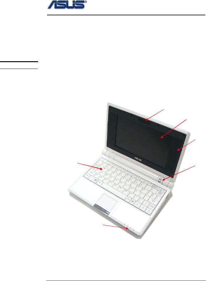
Eee PC 4G (701) Overview
The illustrations below show the overview from front view, right side view, left side view, and rear side view. Most of the parts will be discussed in this manual.
Camera
LCD Panel
LCD Bezel
Keyboard |
Power switch |
Touchpad 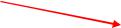
LED status indicator
1 – 2
|
|
Service overview |
LAN port |
USB (2.0) ports |
SPDIF/Headphone |
Modem port |
Air Vents |
Microphone port |
|
USB (2.0) ports |
VGA port |
Card reader |
Kensington Lock |
Front view
Battery Pack |
DC-IN |
1 - 3
C O M P O N E N T S
L C D
I N V E R T E R
B O A R D
M O D U L E
Service overview
Components
The illustrations below show the components of the Eee PC 4G (701).
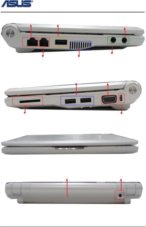
LCD Panel
The illustration below shows the LCD display panel. The Eee PC 4G (701) comes with 7” TFT LCD Panel.
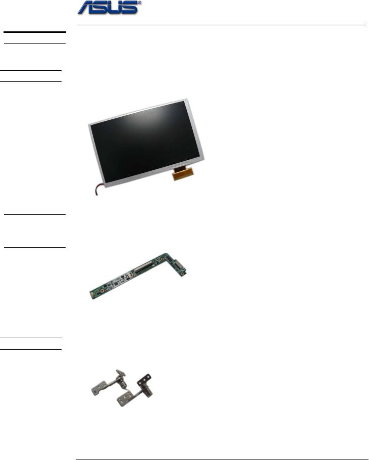
Inverter Board
The illustration below shows the inverter board, which is hidden underneath the lower edge of the LCD front bezel.
L C D H I N G E
LCD Hinge
The illustration below shows the LCD Hinges.
1 - 4
L C D C A S E
Service overview
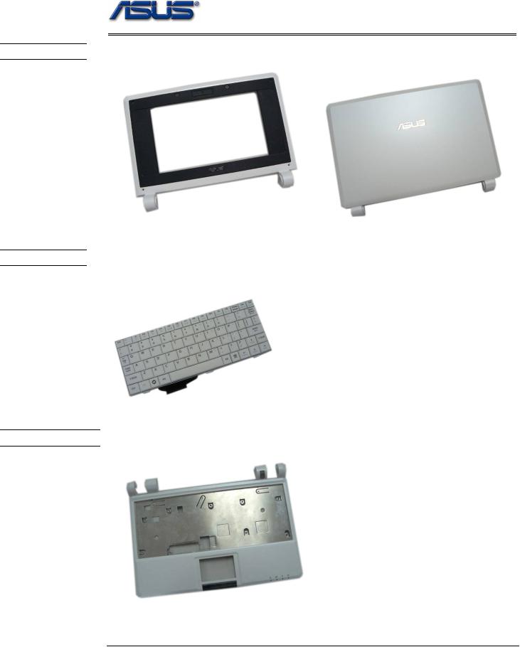
LCD Case
The illustration below shows the LCD case. Here is the LCD front cover, back cover.
K E Y B O A R D
Keyboard
The illustration below shows the keyboard plate. It can be exchanged with keyboard plates with different language layouts, such as U.S., France and others.
T O P C A S E &
Top Case Module
The illustration below shows the top case of the Eee PC 4G (701).
1 - 5
T O U C H P A D
B A T T E R Y
M E M O R Y
Service overview
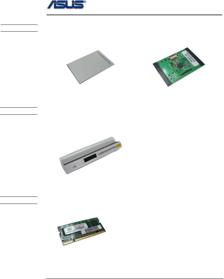
Touch Pad Module
The illustration below shows the Touch Pad module, top and bottom view.
Battery Pack
The illustration below shows the battery packs of the Eee PC 4G (701). It’s located at bottom of the EEE PC 4G (701).
Memory Module
The illustration below shows the memory module for the Eee PC 4G (701).
1 - 6
M O T H E R
B O A R D
M O D U L E
B O T T O M C A S E
W I R E L E S S L A N M O D U L E
Service overview
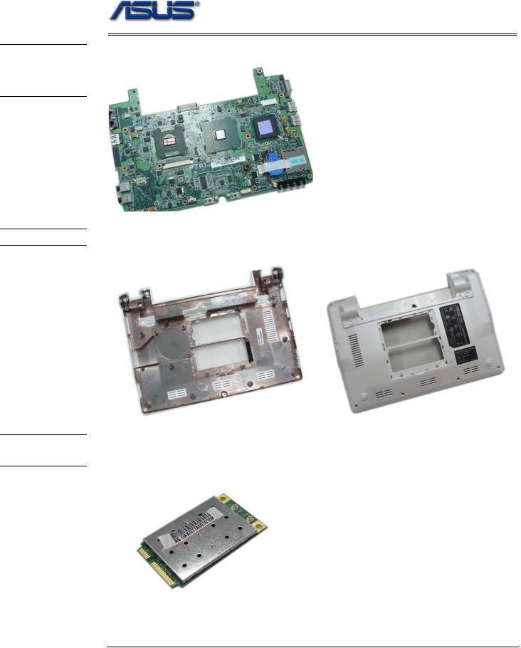
Motherboard Module
The illustration below shows the motherboard module of the Eee PC 4G (701).
Bottom Case Module
The illustration below shows the bottom case module of the Eee PC 4G (701), top and bottom view.
Wireless LAN Module
The illustration below shows the Wireless LAN Module of the Eee PC 4G (701). It contains Wireless LAN Card.
1 - 7
C A U T I O N S
Service overview
Service Overview
Please pay special attention to the cautions below to prevent any damages to the Eee PC 4G (701) and also please be sure to select the appropriate tools described in this section to perform any services desired.
Precautions
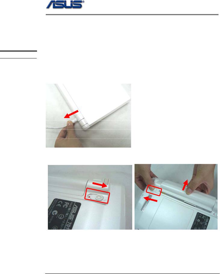
Before you perform any service and or repair on the Eee PC 4G (701), please follow the steps below first.
1.Be sure that the Eee PC 4G (701) is powered down.
2.Disconnect the AC plug from the Eee PC 4G (701)
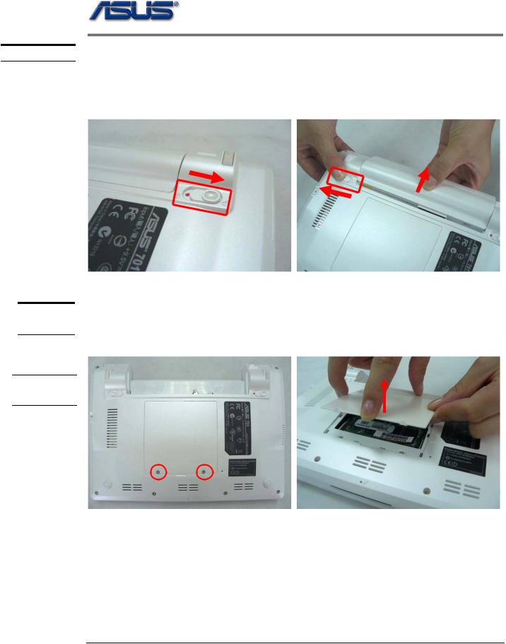
3. Turn the Eee PC 4G (701) over. Unlock latch 1 towards the direction of arrow and then unlock and hold the latch 2 to remove the battery.
2
1
4. Remove all rings, watches and any other metal objects from your hands.
1 - 8
T O O L S
C R O S S
S C R E W -
D R I V E R
F L A T H E A D
S C R E W -
D R I V E R
T W E E Z E R S
I N S E R T I O N
A N D
E X T R A C T I O N T O O L F O R
F P C
C O N N E C T O R
V A C U U M H A N D L I N G T O O L
Service overview
5.Always wear a ground strap on your hand to protect the Eee PC 4G (701) from static discharge.
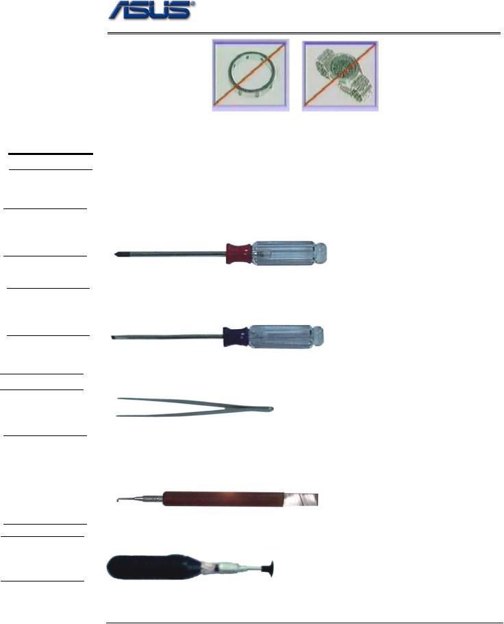
Appropriate Tools
The illustrations below show the appropriate tools that should be used for the Eee PC 4G (701)’s service and repair.
Phillips-head Screwdriver
Use a Phillips-head screwdriver to fasten/remove the K- or B-typed screws.
Single-Slotted Screwdriver
Use a single-slotted screwdriver to lock/unlock the flexible cable connector locks
Tweezers
Use a pair of tweezers to remove/insert flexible cables.
Insertion and extraction tool for FPC connector
Use insertion and extraction tool for FPC connector to handle locking and unlocking of FPC connectors.
Vacuum Handling Tool
1 - 9

D I S A S S E M B L Y
C A U T I O N S
Service overview
Disassembly Cautions
Before you perform any service and or repair on the Eee PC 4G (701), please read the notice below first.
ASUS hereby provides a basic instruction for the disassembly of ASUS products, i.e. to remove components and materials that require selective treatments, which are defined by Annex II of the European Union (EU) Waste Electrical and Electronic Equipment (WEEE) Directive 2002/96/EC. This instruction is intended for the use of end-of-life recyclers or treatment facilities. Following is the list of Annex II of EU WEEE Directive 2002/96/EC.
-polychlorinated biphenyls (PCB) containing capacitors in accordance with Council Directive 96/59/EC of 16 September 1996 on the disposal of polychlorinated biphenyls and polychlorinated terphenyls (PCB/PCT),
-mercury containing components, such as switches or backlighting lamps,
-batteries,
-printed circuit boards of mobile phones generally, and of other devices if the surface of the printed circuit board is greater than 10 square centimetres,
-toner cartridges, liquid and pasty, as well as colour toner,
-plastic containing brominated flame retardants,
-asbestos waste and components which contain asbestos,
-cathode ray tubes,
-chlorofluorocarbons (CFC), hydrochlorofluorocarbons (HCFC) or hydrofluorocarbons (HFC), hydrocarbons (HC),
-gas discharge lamps,
-liquid crystal displays (together with their casing where appropriate) of a surface greater than 100 square centimeters and all those back-lighted with gas discharge lamps,
-external electric cables,
-components containing refractory ceramic fibres as described in Commission Directive 97/69/EC of 5 December 1997 adapting to technical progress Council Directive 67/548/EEC relating to the classification, packaging and labelling of dangerous substances,
-components containing radioactive substances with the exception of components that are below the exemption thresholds set in Article 3 of and Annex I to Council Directive 96/29/Euratom of 13 May 1996 laying down basic safety standards for the protection of the health of workers and the general public against the dangers arising from ionising radiation,
-electrolyte capacitors containing substances of concern (height > 25 mm, diameter > 25 mm or proportionately similar volume)
1 - 10
Disassembly procedure
2Chapter
Disassembly Procedure
Please follow the information provided in this section to perform the complete disassembly procedure of the Eee PC 4G (701). Be sure to use proper tools described before.
SUS Eee PC 4G (701)consists of various modules. This chapter describes the procedures Afor the complete Eee PC 4G (701) disassembly. In addition, in between procedures, the detailed disassembly procedure of individual modules will be provided for your service
needs.
The disassembly procedure consists of the following steps:
•Battery Module
•Memory Module
•Keyboard Module
•WLAN Module
•Top Case Module
•LCD Module
•Motherboard Module
2 - 1
B A T T E R Y
M E M O R Y M O D U L E
M E M O R Y R E M O V A L
Disassembly procedure
Battery Module
The illustration below shows how to remove the battery module.
Remove battery module
1 Slide the battery lock to open it
2 Slide the battery latch and hold the battery to remove it from system.
1
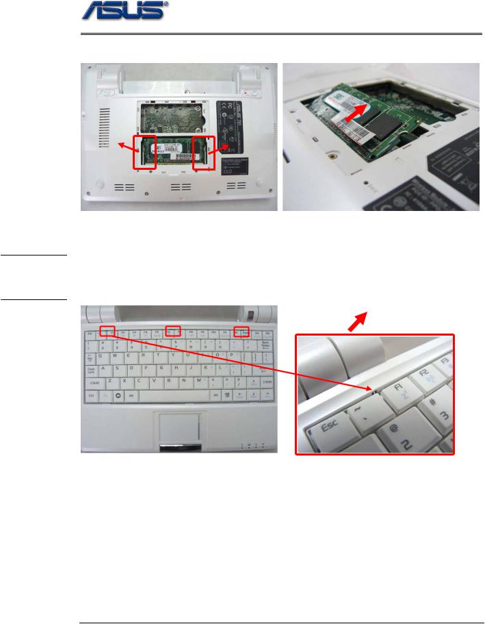
Memory Module
The illustration shows how to remove the memory module form the Eee PC 4G (701).
Removing Memory module
1. Remove 2 screws (M2*4) on the memory cover then remove it from the system.
2 - 2
K E Y B O A R D
M O D U L E
R E M O V A L
Disassembly procedure
2.Softly open the two latches to pop the memory module up at 45 degree angles and then remove the memory at that angle.
Keyboard Module
The illustration of below shows how to remove the keyboard
Removing Keyboard
1. Turn over the NB and push the 3 latches (F1; F6;Pause) on keyboard module to lift the keyboard plate.
2 - 3
Disassembly procedure
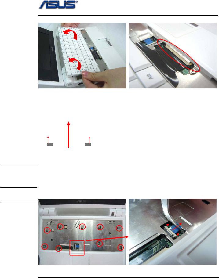
2. Place the keyboard plate on the top case and disconnect the keyboard FPC to remove.
Removing Keyboard Cable
1.Use a flexible connector tool to unlock the cable connector on both ends (no. 1).
2.Carefully pull out the keyboard cable (no. 2) with a pair of tweezers.
3.Lock the connector (no. 3) again to avoid possible breakage.
2.Cable out
T O P C A S E M O D U L E
T O P C A S E R E M O V A L
1. Unlock |
1. Unlock |
|
3.

 3.
3.
Top Case Module
The illustrations below show how to disassemble and remove the top case module of the Eee PC 4G (701). The module contains the top case itself.
Removing Top Case Module
1. Disconnect the touch pad FPC and then remove 9 screws (M2*4) on top case.
2 - 4
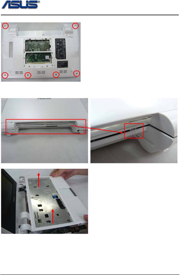
Disassembly procedure
2. Close and turn the system upside down to remove 6 screws (M2*4) on the bottom case.
3.Softly pry the four sides of the system to open the latch hooks securing the top case with bottom case, then remove the top case.
2 - 5
Disassembly procedure
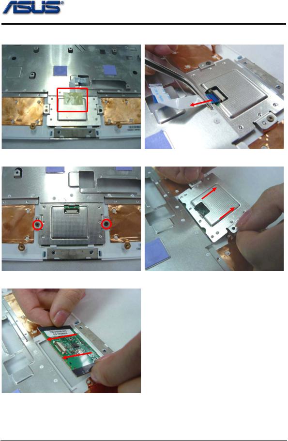
4.Remove 1 piece of tape on the touch pad FPC then open the latch to disconnect it from touch pad board.
5. Remove 2 screws (M2*3) securing touch pad bracket and then remove the bracket.
6. Remove the touch pad board from the top case.
2 - 6
 Service Manual")
W L A N
M O D U L E
W L A N
M O D U L E R E M O V A L
Disassembly procedure
WLAN Module
The illustrations below show how to remove the WLAN module from the Eee PC 4G (701).
Remove WLAN module
1.Remove 3 pieces of tape fixing the cable and then disconnect the following 4 cables, namely speaker cable, CMR cable, Fan cable, LVDS cable.
Speaker cable |
|
|
Camera cable |
Fan cable |
LVDS cable |
|
|
2.Remove 1 piece of tape fixing the microphone cable and disconnect the microphone cable from the mother board, and then take the microphone module away.
2 - 7
Disassembly procedure
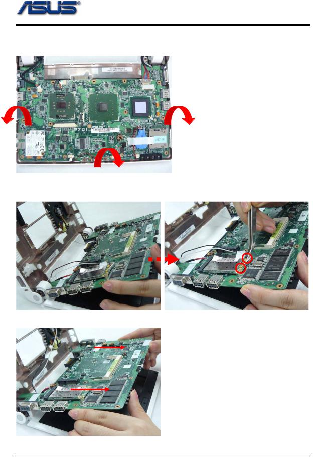
3.Lift the mother board from bottom case by softly separating from the bottom side, two sides to the top.* pay attention not to remove the mother board for now, for that the WLAN antenna is still connected with the mother board.
4. Turn the LCD with its back cover on the platform and hold the mother board while disconnecting the two antennas.
5. Remove the mother board from the bottom case.
2 - 8

M O T H E R
B O A R D
M O T H E R B O A R D
R E M O V A L
Disassembly procedure
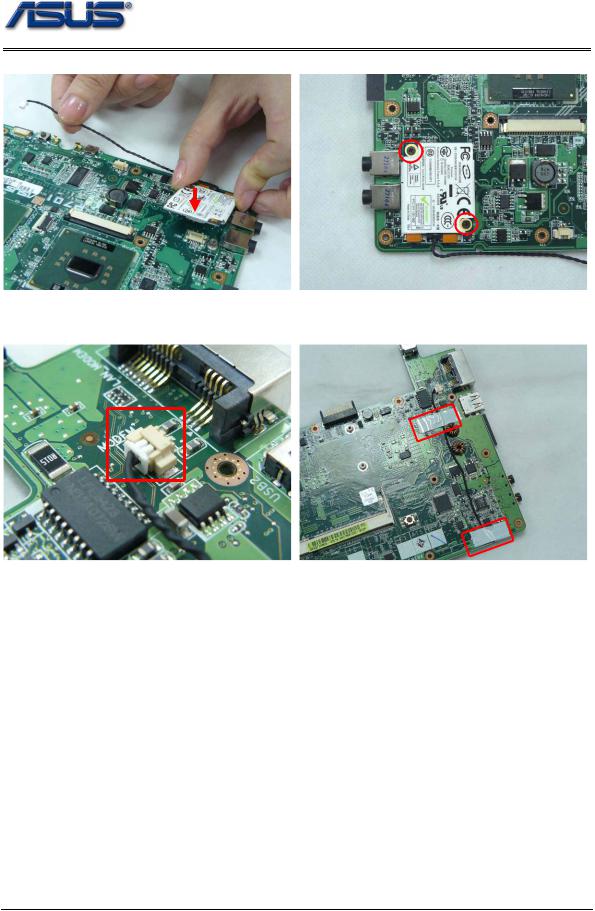
6. Remove 2 screws (M2*4) on the WLAN module to pop up the module at 30 degree angles and then remove it at that angle.
Motherboard
The illustrations below show how to disassemble and remove the Motherboard.
Removing Motherboard
1.Tear off 2 pieces of tape fixing the Modem cable and disconnect the Modem cable from mother board.
2 - 9

Disassembly procedure
2.Remove two screws (M2*3) securing the Modem module and then remove it from the mother board.
3. Remove 2 screws screwing the LCD hinges and then take the LCD display away.
4.Remove 1 piece of tape and 3 screws (M*4) securing the Fan module and then take the Fan module away.
2 - 10
L C D M O D U L E
L C D M O D U L E D I S A S S E M B L Y
Disassembly procedure
LCD Module
The illustrations below show how to remove and disassemble the LCD module. The module contains LCD panel, Inverter board, LCD bezel, LCD back cover.
Disassembling LCD Module
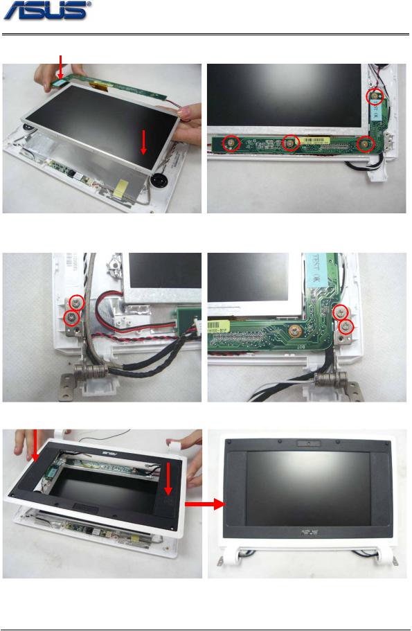
1.Remove 8 rubber pads and screws (M2*4) on LCD front bezel.
2. Pry the four inner sides of LCD front bezel and separate it from LCD module.
3. Remove 2 screws (M2*4) on each LCD hinge and remove both hinges.
2 - 11
Disassembly procedure
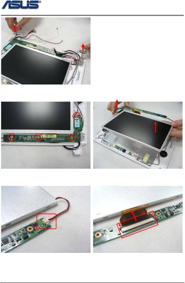
4.Unscrew 4 (M2*4) screws securing the inverter board and then take the LCD panel together with the inverter board away from LCD back cover .
5. Disconnect the inverter cable, LCD FPC cable from inverter board and take the board away.
2 - 12
Disassembly procedure
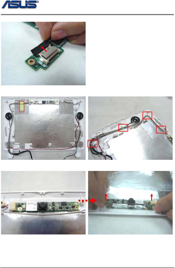
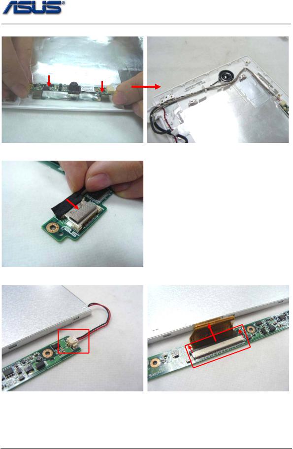
6. Disconnect the coaxial cable from inverter board.
7. Tear off 1 piece of tape fixing camera cable and take the camera cable off cable guide.
8. Remove the camera board from LCD back cover and then take the whole module away.
2 - 13
Disassembly procedure
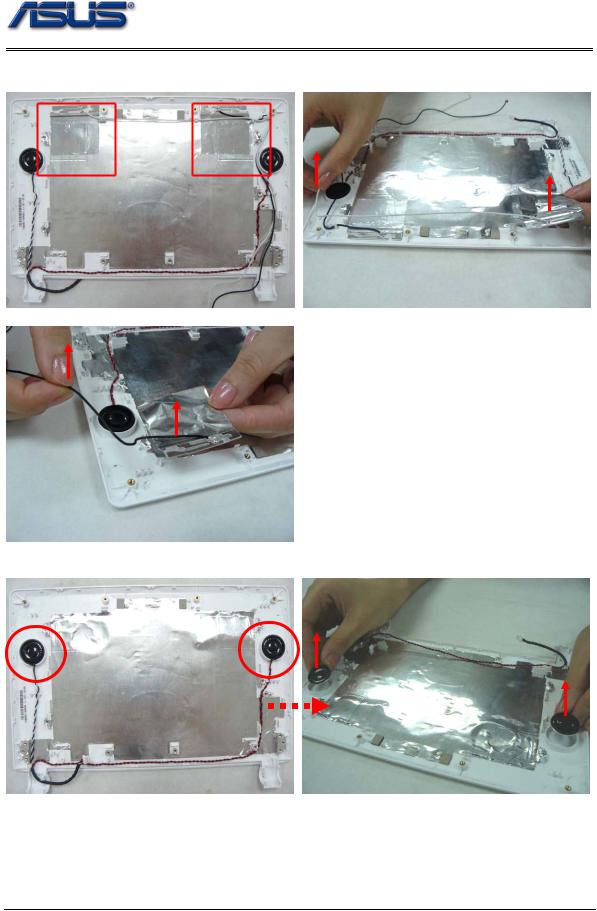
9. Take the WLAN antennas off cable guides and remove the antennas together with its tape from LCD back cover.
10. Take the speaker cables off cable guides and remove both speakers from their slots.
2 - 14
Assembly procedure
3Chapter
Assembly Procedure
Please follow the information provided in this section to perform the complete assembly procedure of the Eee PC 4G (701). Be sure to use proper tools described before.
fter you have completed the previous chapter of complete disassembly, please follow this Achapter to assemble the Eee PC 4G (701) back together. This chapter describes the procedures of the complete Eee PC 4G (701) assembly. In addition, in between procedures, the detailed assembly procedure of individual modules will be provided for
your service needs.
The assembly procedure consists of the following steps:
•LCD Module
•Motherboard Module
•Top Case Module
•WLAN Module
•Keyboard Module
•Memory Module
•Battery Module
3 - 1
Assembly procedure
L C D M O D U L E LCD Module
The illustrations below show how to assemble and install the LCD module of the Eee PC 4G (701).
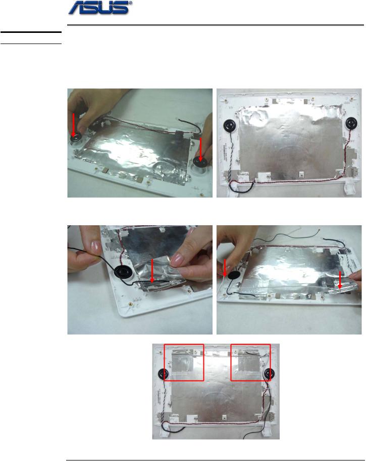
1. Install the two speakers on LCD back cover and arrange the speaker cable well through cable guide.
2. Assembly the black and white antennas on LCD back cover and well arrange the antanna cables through cable guides.
3 - 2
Assembly procedure
3. Install the camera board on LCD back cover, pay attention to the aiming pole.
4. Connect the coaxial cable with inverter board.
5. Connect the inverter cable, LCD FPC cable with inverter board.
3 - 3
Assembly procedure
6. Install the LCD panel together with the inverter board on LCD back cover and then secure 4 screws (M2*4) on it.
7. Assemble both hinges and secure 2 screws (M2*4) on each.*pay attention to differences between the left and right.
8. Install the LCD front bezel on LCD back cover and press the sides to fix them well.
3 - 4
Assembly procedure
9. Secure 6 screws (M2*4)on LCD front bezel and then fix 6 rubber pads on it.
 Motherboard
M O T H E R B O A R D |
The illustrations below show how to assemble and install the motherboard of the Eee |
|
|
|
PC 4G (701). |
M O T H E R B O A R D
A S S E M B L Y
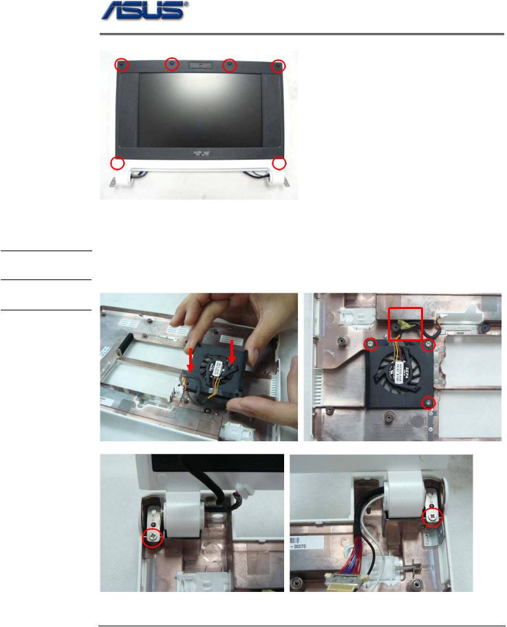
1. Install the Fan module on bottom case, secure 3 screws on it and fix 1 piece of tape on the cable.
2. Hold the LCD to fix its hinges on bottom case and then secure 2 screws(M2*4).
3 - 5
Assembly procedure
3. Connect the Modem module with the mother board and then secure 2 scews (M2*3) .
4. Connect the Modem cable with the mother board and then arrange the cable to fix 2 pieces of tape on it.
3 - 6
 Loading...