


Version 1.0
Published September 2020
is device complies with Part 15 of the FCC Rules. Operation is subject to the following
two conditions:
(1) this device may not cause harmful interference, and
(2) this device must accept any interference received, including interference that
may cause undesired operation.
CALIFORNIA, USA ONLY
e Lithium battery adopted on this motherboard contains Perchlorate, a toxic substance
controlled in Perchlorate Best Management Practices (BMP) regulations passed by the
California Legislature. When you discard the Lithium battery in California, USA, please
follow the related regulations in advance.
“Perchlorate Material-special handling may apply, see www.dtsc.ca.gov/hazardouswaste/
perchlorate”

AUSTRALIA ONLY
Our goods come with guarantees that cannot be excluded under the Australian Consumer
Law. You are entitled to a replacement or refund for a major failure and compensation for
any other reasonably foreseeable loss or damage caused by our goods. You are also entitled
to have the goods repaired or replaced if the goods fail to be of acceptable quality and the
failure does not amount to a major failure.
e terms HDMI® and HDMI High-Denition Multimedia Interface, and the
HDMI logo are trademarks or registered trademarks of HDMI Licensing LLC in the
United States and other countries.

Contents
Chapter 1 Introduction 1
1.1 Package Contents 1
1.2 Specications 2
1.3 Motherboard Layout 5
1.4 Front Panel 7
1.5 Rear Panel 8
Chapter 2 Installation 9
2.1 Installing Memory Modules (SO-DIMM) 10
2.2 Onboard Headers and Connectors 11
2.3 Smart Switch 12
2.4 M.2 WiFi/BT Module Installation Guide 13
2.5 M.2_SSD (NGFF) Module Installation Guide (M2_1) 15
Chapter 3 Software and Utilities Operation 17
3.1 Installing Drivers 17
Chapter 4 UEFI SETUP UTILITY 18
4.1 Introduction 18
4.1.1 UEFI Menu Bar 18
4.1.2 Navigation Keys 19
4.2 Main Screen 20
4.3 OC Tweaker Screen 21
4.4 Advanced Screen 23

4.4.1 CPU Conguration 24
4.4.2 Onboard Devices Conguration 25
4.4.3 Storage Conguration 27
4.4.4 ACPI Conguration 28
4.4.5 Trusted Computing 29
4.5 Tools 30
4.6 Hardware Health Event Monitoring Screen 31
4.7 Security Screen 32
4.8 Boot Screen 33
4.9 Exit Screen 35

Chapter 1 Introduction
ank you for purchasing FP6D4-P1 motherboard. In this documentation, Chapter
1 and 2 contains the introduction of the motherboard and step-by-step installation
guides. Chapter 3 contains the operation guide of the soware and utilities. Chapter
4 contains the conguration guide of the BIOS setup.
Becau se the motherboard specications and the BIOS soware might be updated, the
content of this documentation will be subject to change without notice.
Becau se the motherboard specications and the BIOS soware might be updated, the
content of this documentation will be subject to change without notice.
1.1 Package Contents
FP6D4-P1 Motherboard
•
FP6D4-P1 Quick Insta llation Guide
•
FP6D4-P1 Support CD
•
1 x Screw for M.2 Socket (M2*2) (Optional)
•
1 x Screw for WiFi Module (M2*2) (Optional)
•
FP6D4-P1
English

1.2 Specications
Platform
CPU
Chipset
Memory
•
•
•
•
•
•
•
•
7.0-in x 5.7-in, 17.8 cm x 14.5 cm
Supports AMD FP6 Renoir
3 Power Phase design
SOC
Dual Channel DDR4 Memory Technology
2 x DDR4 SO-DIMM Slots
Supports DDR4 3200/2933/2800/2666/2400/2133 non-ECC,
un-buered memory
Max. capacity of system memory: 64GB
English
Expansion
Slot
Graphics
1 x M.2 Socket (Key E), supports type 2230 WiFi/BT module
•
Integrated AMD RadeonTM Vega Series Graphics in Ryzen
•
Series APU*
* Actual support may vary by CPU
DirectX 12, Pixel Shader 5.0
•
Shared memory default 2GB.
•
Dual graphics output: support D-Sub and HDMI ports by
•
independent display controllers
Supports HDMI with max. resolution up to 4K@ 60Hz
•
Supports D-Sub with max. resolution up to 1920x1200 @
•
60Hz
Supports Auto Lip Sync, Deep Color (12bpc), xvYCC and
•
HBR (High Bit Rate Audio) with HDMI 1.4 Port (Compliant
HDMI monitor is required)
Supports HDCP 2.3 with HDMI 1.4 Port
•
2 3

Audio
LAN
Front
Panel I/O
Rear Panel
I/O
Realtek ALC233 Audio Codec
•
1 x Headphone/Headset Jack
•
1 x MIC-In
•
PCIE x1 Gigabit LAN 10/100/1000 Mb/s
•
Realtek RTL8111H
•
Supports Wake-On-LAN
•
Supports Lightning/ESD Protection
•
Supports Energy Ecient Ethernet 802.3az
•
Supports PXE
•
1 x Power Button
•
2 x USB 3.2 Gen1 Type-A Ports (Support ESD Protection)
•
1 x USB 3.2 Gen1 Type-C Port (Supports ESD Protection)
•
2 x USB 2.0 Ports (Supports ESD Protection)
•
* USB_3_QC supports supports Quick Charge.
1 x SD Card Socket
•
1 x DC Jack (Compatible with the 19V power adapter)*
•
1 x D-Sub Port
•
1 x HDMI Port
•
2 x USB 3.2 Gen1 Type-A Ports (Support ESD Protection)
•
1 x RJ-45 LAN Port with LED (ACT/LINK LED and SPEED
•
LED)
1 x Headphone Jack
•
1 x Microphone Input Jack
•
FP6D4-P1
Storage
Connector
BIOS
Feature
1 x SATA3 6.0 Gb/s with Power Connector , support NCQ,
•
AHCI and Hot Plug*
1 x Ultra M.2 Socket (M2_1), supports type 2260/2280 M.2
•
SATA3 6.0 Gb/s module and M.2 PCI Express module up to
Gen3 x4 (32 Gb/s)*
* Supports NVMe SSD as boot disks
1 x CPU Fan Connector (4-pin)
•
AMI UEFI Legal BIOS with multilingual GUI support
•
ACPI 6.0 Compliant wake up events
•
SMBIOS 2.7 Support
•
English

Hardware
Monitor
OS
Certications
CPU Temperature Sensing
•
CPU Fan Tachometer
•
CPU Quiet Fan (Auto adjust chassis fan speed by CPU
•
temperature)
CPU Fan Multi-Speed Control
•
Voltage monitoring: CPU Vcore, VCCM, +5V, +3.3V
•
Microso® Windows® 10 64-bit
•
FCC, CE
•
ErP/EuP ready (ErP/EuP ready power supply is required)
•
English
4 5
3
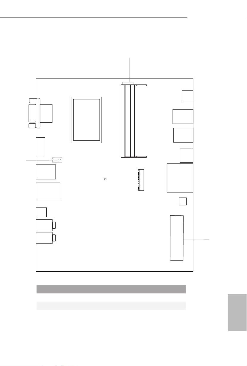
1.3 Motherboard Layout
VGA1
HDMI 1
1
CPU_FAN1
USB 3.2 Gen1
T: USB_6
B: USB_5
RJ-45
DC Jack
Headphone
1
DDR4_A1
DDR4_B1
FP6D4-P1
RoHS
FP6D4-P1
Power
Button
USB 3.2 Gen1
T: USB_2
USB2.0
B: USB_1
USB 3.2 Gen1
T: USB_4
USB2.0
B: USB_3
USB 3.2 Gen1
B: USB3_TC_1
SD Card
M.2 W LAN
BIOS
ROM
Mic In
SATA3_1
2
No. Description
1 2 x 260-pin DDR4 SO-DIMM Slots (DDR4_A1, DDR4_B1)
2 SATA3 Connector (SATA3_1)
3 CPU Fan Connector (CPU_FAN1)
English
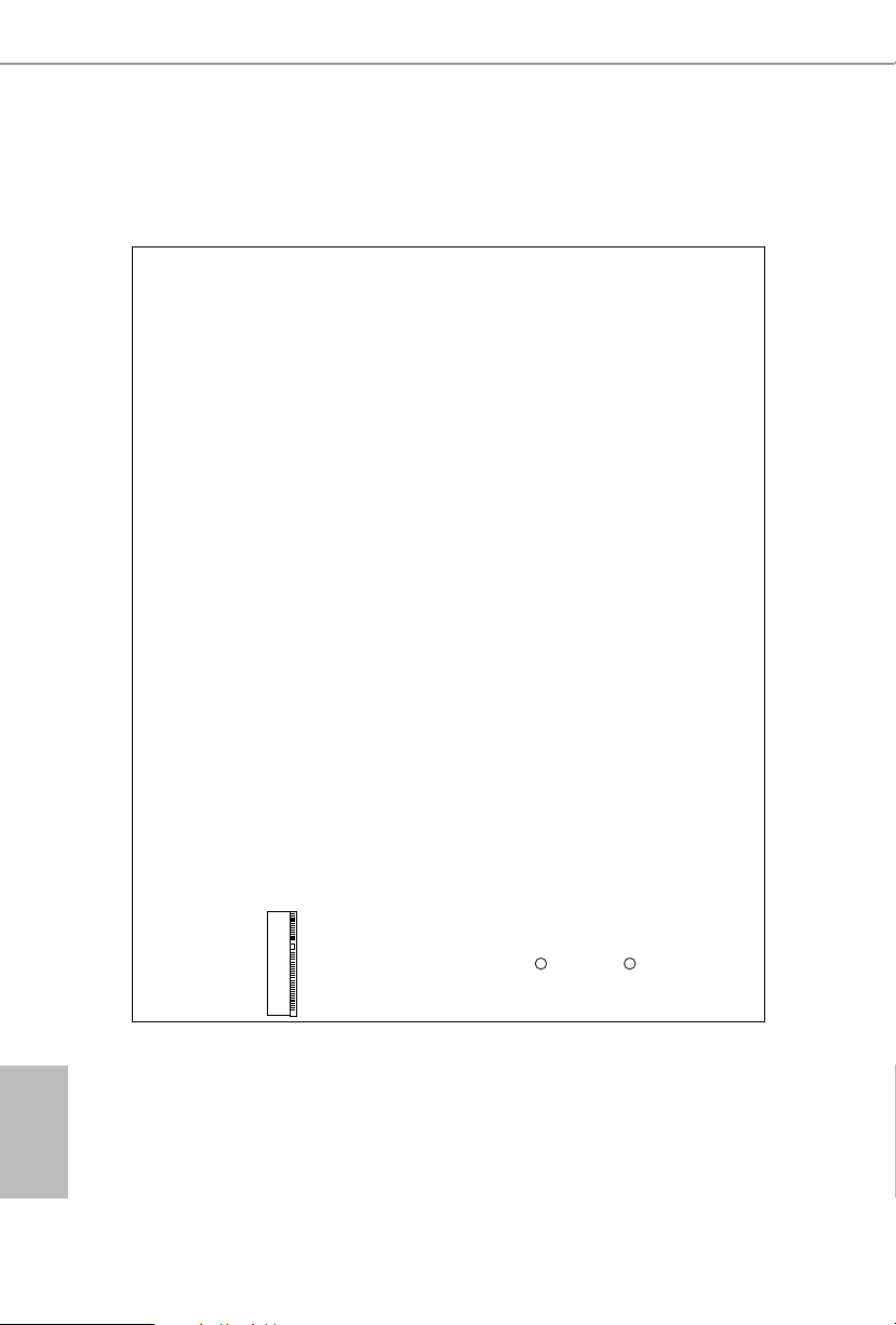
Back Side View
M.2 SSD
English
6 7
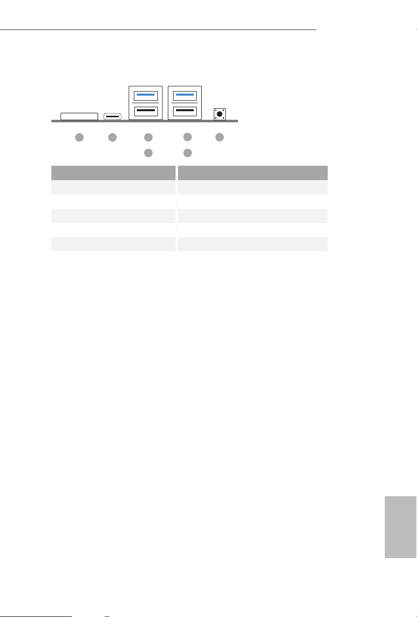
1.4 Front Panel
FP6D4-P1
21 3
4 6
No. Description No. Description
1 SD Card Socket 4 USB 2.0 Port (USB_3)*
2 USB 3.2 Gen1 Type-C Port *Quick Charger Support
(USB3_TC_1) 5 USB 3.2 Gen1 Type-A Port (USB_2)
3 USB 3.2 Gen1 Type-A Port 6 USB 2.0 Port (USB_1)
(USB_4) 7 Power Button (S W1)
5
7
English
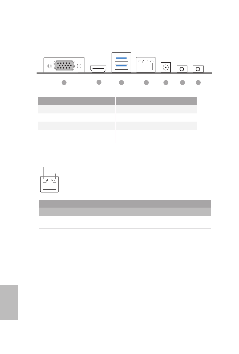
1.5 Rear Panel
1 43 5 6 7
2
No. Description No. Description
1 D-Sub Port 4 LAN RJ-45 Port*
2 HDMI Port 5 DC Jack
3 USB 3.2 Gen1 Type-A Port 6 Headphone Jack
(USB_ 5_6) 7 Microphone Input
* ere are two LEDs on each LAN por t. Please refe r to the table below for the LAN por t LED indications.
ACT/LINK LED
SPEED LED
LAN Por t
Activity / Link LED Speed LED
Status Description Status Description
O No Link O 10Mbps connection
Blinking Data Activity Green 100Mbps connection
On Link Orange 1Gbps connection
English
8 9

Chapter 2 Installation
is is a Proprietary form factor motherboard. Before you install the motherboard,
study the conguration of your chassis to ensure that the motherboard ts into it.
Pre-installation Precautions
Take note of the following precautions before you install motherboard components
or change any motherboard settings.
Make sure to unplug the power cord before installing or removing the motherboard
•
components. Failure to do so may cause physical injuries and damages to motherboard
components.
In order to avoid damage from static electricity to the motherboard’s components,
•
NEVER place your motherboard directly on a carpet. Also remember to use a grounded
wrist strap or touch a safety grounded object before you handle the components.
Hold components by the edges and do not touch the ICs.
•
Whenever you uninstall any components, place them on a grounded anti-static pad or
•
in the bag that comes with the components.
When placing screws to secure the motherboard to the chassis, please do not over-
•
tighten the screws! Doing so may damage the motherboard.
FP6D4-P1
English

2.1 Installing Memory Modules (SO-DIMM)
is motherboard provides two 260-pin DDR4 (Double Data Rate 4) SO-DIMM
slots.
It is not allowed to install a DDR, DDR 2 or DDR3 memory module into a DDR4 slot;
otherwise, this motherboard and SO -DIMM may be damaged.
e SO-DIMM only ts in one correct orientation. It will cause permanent damage to
the motherboard and the SO-DIMM if you force the SO-DIMM into the slot at incorrect
orientation.
1. Carefully insert the SO-DIMM memory modules into the slot at a 30-degree angle.
2. Push down until the modules snap into place.
English
10 11
2.2 Onboard Headers and Connectors
FAN_SPEED_CONTROL
Onboard headers and connec tors are NOT jumpers. Do NOT place jumper caps ove r these
heade rs and connectors. Placing jumper caps over the h eaders and connec tors will cause
permanent damage to the motherboard.
FP6D4-P1
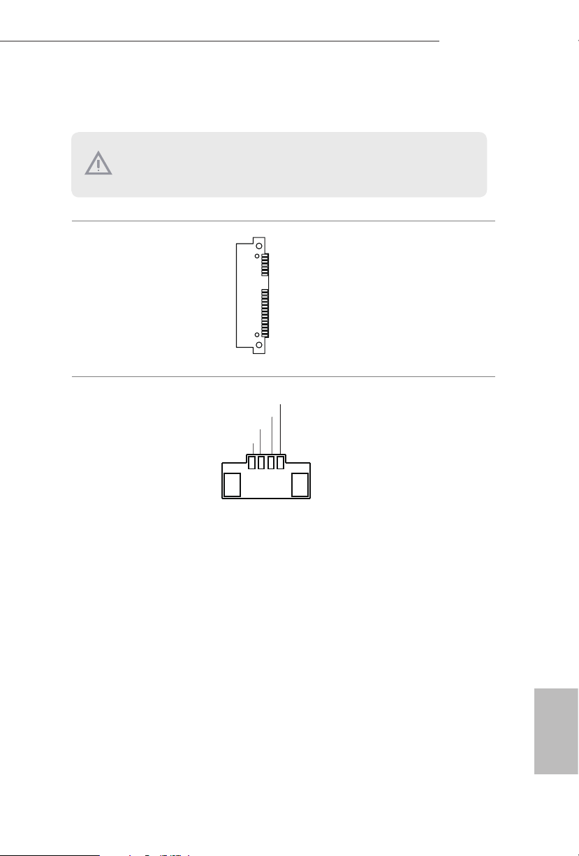
Serial ATA3 Connector
(SATA3_1:
see p.5, No. 2)
CPU Fan Connectors
(4-pin CPU_FAN1)
(see p.5, No. 3)
CPU_FAN_SPEED
FAN_VOLTAGE
GND
1 2 3 4
is SATA3 connector
supports SATA data cables
for internal storage devices
with up to 6.0 Gb/s data
transfer rate.
is motherboard
provides a 4-Pin CPU fan
(Quiet Fan) connector. If
you plan to connect a 3-Pin
CPU fan, please connect it
to Pin 1-3.
English

2.3 Smart Switch
e motherboard has one smart switch: Power Button.
Power Button
(SW1)
(see p.7, No. 7)
Power Button allows users
to quickly turn on/o the
system.
English
12 13
FP6D4-P1
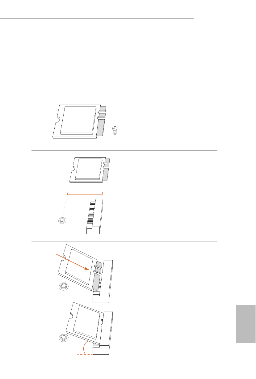
2.4 M.2 WiFi/BT Module Installation Guide
e M.2, also known as the Next Generation Form Factor (NGFF), is a small size and
versatile card edge connector that aims to replace mPCIe and mSATA. e M.2 Socket (Key
E) supports type 2230 WiFi/BT module.
* e M.2 socket does not support SATA M.2 SSDs.
Installing the WiFi/BT module
Step 1
Prepare a type 2230 WiFi/BT module
and the screw.
Step 2
Find the nut location to be used.
PCB Length: 3cm
Module Type: Type2230
A
Step 3
Gently insert the WiFi/BT module
into the M.2 slot. Please be aware
that the module only ts in one
orientation.
A
English
o
A
20

Step 4
Tighten the screw with a screwdriver
to secure the module into place.
Please do not overtighten the screw as
this might damage the module.
A
English
14 15
FP6D4-P1
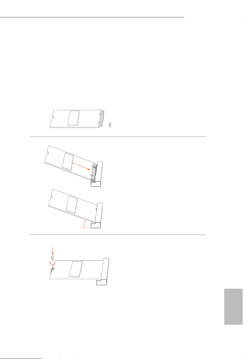
2.5 M.2_SSD (NGFF) Module Installation Guide (M2_1)
e Ultra M.2, also known as the Next Generation Form Factor (NGFF), is a small size
and versatile card edge connector that aims to replace mPCIe and mSATA. e Ultra M.2
Socket (M2_1) supports type 2260/2280 M.2 SATA3 6.0 Gb/s module and M.2 PCI Express
module up to Gen3 x4 (32 Gb/s).
Installing the M.2_SSD (NGFF) Module
Step 1
Prepare a M.2_SSD (NGFF) module
and the screw.
Step 2
Gently insert the M.2 (NGFF) SSD
module into the M.2 slot. Please
be aware that the M.2 (NGFF) SSD
module only ts in one orientation.
o
20
Step3
Tighten the screw with a screwdriver
to secure the module into place.
Please do not overtighten the screw as
NUT1NUT2
this might damage the module.
English

English
M.2_SSD (NGFF) Module Support List
Vendor Interface P/N
ADATA PCIe ADATA ASX7000NPC-512GT-C (XPG SX7000) (NVMe)
ADATA PCIe ADATA ASX8000NPC-512GM-C (XPG ASX8000) (NVMe)
Apacer PCIe Apacer Z280 AP240GZ280-240G (NVMe)
Intel PCIe Intel Optane Memory 32GB (MEMPEK1W032GA)(NVMe)
Intel PCIe Intel Optane Memory 16GB (MEMPEK1W016GA)(NVMe)
INTEL PCIe INTEL 600P-SSDPEKKW256G7-256GB (NVMe)
INTEL PCIe INTEL 600P-SSDPEKKW128G7-128GB (NVMe)
INTEL PCIe INTEL 6000P-SSDPEKKF256G7-256GB (NVMe)
INTEL PCIe INTEL 6000P-SSDPEKKF512G7-512GB (NVMe)
Kingston PCIe Kingston SHPM2280P2/240G
PAT RIO T PCIe PATRIOT Hellre M2 (240G) (NVMe)
PLEXTOR PCIe PLEXTOR PX-256M8PeG (NVMe)
PLEXTOR PCIe PLEXTOR PX-256M8SeGN (NVMe)
Samsung PCIe Samsung XP941-512G (MZHPU512HCGL)
Samsung PCIe Samsung 950Pro-512G (NVMe)
Samsung PCIe Samsung 950Pro-256G (NVMe)
Samsung PCIe Samsung MZ-VLW1280 (PM961) (NVMe)
Samsung PCIe Samsung MZ-VPW1280 (SM961) (NVMe)
TOSHIBA PCIe TOSHIBA XG3-128G (NVMe)
TOSHIBA PCIe TOSHIBA OCZ RD400-256G (NVMe)
WD PCIe WD WDS512G1X0C-00ENX0 (NVMe)
WD PCIe WD WDS256G1X0C-00ENX0 (NVMe)
ADATA SATA ADATA - SU800-SU800NS38-256GT-C-256G
ADATA SATA ADATA - SU800-SU800NS38-512GT-C-512G
Crucial SATA Crucial-CT240M500SSD4-240GB
Ezlink SATA Ezlink P51B-80-120GB
INTEL SATA INTEL-535-SSDSCKJF240A5-QS63-MLC-240G
INTEL SATA INTEL 540S-SSDSCKKW240H6-240GB
Kingston SATA Kingston-RBU-SNS8400S3/180GD
LITON SATA LITON LJ H-256V2G-11-256GB
PLEXTOR SATA PLEXTOR - M7V-PX-128M7VG-128GB
PLEXTOR SATA PLEXTOR PX-128M6G-128GB
Sandisk SATA Sandisk X400-SD8SN8U-128G
Sandisk SATA Sandisk Z400s-SD8SNAT-128G
Tra nscend SATA Transcend TS256GMTS800-256GB
V-Co lo r SATA V-C olo r 120G
V-Co lo r SATA V-C olo r 24 0G
WD SATA WD BLUE WDS100T1B0B
WD SATA WD Green WDS240G1G0B-00RC30
For the latest updates of M.2_SSD (NFGG) module support list, please visit our website for
details.
16 17

Chapter 3 Software and Utilities Operation
3.1 Installing Drivers
e Support CD that comes with the motherboard contains necessary drivers and
useful utilities that enhance the motherboard’s features.
Running The Support CD
To begin using the support CD, insert the CD into your CD-ROM drive. e CD
automatically displays the Main Menu if “AUTORUN” is enabled in your computer.
If the Main Menu does not appear automatically, locate and double click on the le
“ASRSETUP.EXE” in the Support CD to display the menu.
Drivers Menu
e drivers compatible to your system will be auto-detected and listed on the
support CD driver page. Please click Install All or follow the order from top to
bottom to install those required drivers. erefore, the drivers you install can work
properly.
Utilities Menu
e Utilities Menu shows the application soware that the motherboard supports.
Click on a specic item then follow the installation wizard to install it.
FP6D4-P1
English

Chapter 4 UEFI SETUP UTILITY
4.1 Introduction
is section explains how to use the UEFI SETUP UTILITY to congure your
system. You may run the UEFI SETUP UTILITY by pressing <F2> or <Del> right
aer you power on the computer, otherwise, the Power-On-Self-Test (POST) will
continue with its test routines. If you wish to enter the UEFI SETUP UTILITY aer
POST, restart the system by pressing <Ctl> + <Alt> + <Delete>, or by pressing the
reset button on the system chassis. You may also restart by turning the system o
and then back on.
Becau se the UEFI soware is constantly being updated, the following UEFI setup
screens and descriptions are for reference purpose only, and they may not exactly
match what you see on your screen.
4.1.1 UEFI Menu Bar
e top of the screen has a menu bar with the following selections:
Main
OC Tweaker
Advanced
Tool
H/W Monitor
Security
Boot
For setting system time/date information
For overclocking congurations
For advanced system congurations
Useful tools
Displays current hardware status
For security settings
For conguring boot settings and boot priority
English
Exit
18 19
Exit the current screen or the UEFI Setup Utility

4.1.2 Navigation Keys
Use < > key or < > key to choose among the selections on the menu bar, and
use < > key or < > key to move the cursor up or down to select items, then
press <Enter> to get into the sub screen. You can also use the mouse to click your
required item.
Please check the following table for the descriptions of each navigation key.
Navigation Key(s) Description
FP6D4-P1
+ / -
<Tab>
<PGUP>
<PGDN>
<HOME>
<END>
<F1>
<F7>
<F9>
<F10>
<F12>
<ESC>
To change option for the selected items
Switch to next function
Go to the previous page
Go to the next page
Go to the top of the screen
Go to the bottom of the screen
To display the General Help Screen
Discard changes and exit the SETUP UTILITY
Load optimal default values for all the settings
Save changes and exit the SETUP UTILITY
Print screen
Jump to the Exit Screen or exit the current screen
English
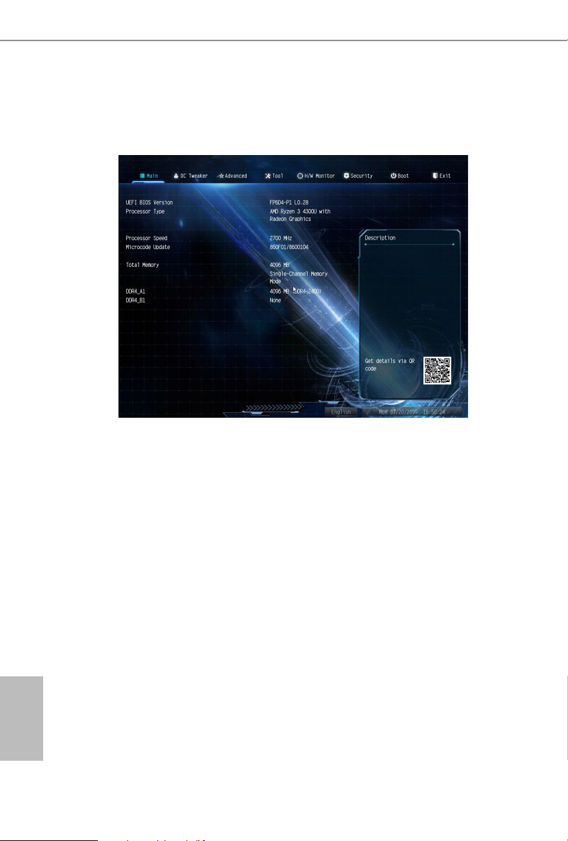
4.2 Main Screen
When you enter the UEFI SETUP UTILITY, the Main screen will appear and
display the system over view.
English
20 21

4.3 OC Tweaker Screen
In the OC Tweaker screen, you can set up overclocking features.
FP6D4-P1
Becau se the UEFI soware is constantly being updated, the following UEFI setup
screens and descriptions are for reference purpose only, and they may not exactly
match what you see on your screen.
Load XMP Setting
Load XMP settings to overclock the memory and perform beyond standard
specications.
DRAM Frequency
If [Auto] is selected, the motherboard will detect the memory module(s) inserted
and assign the appropriate frequency automatically. Setting DRAM Frequency can
adjust DRAM Timing.
English

DRAM Timing Conguration
Voltage Conguration
DRAM Voltage
Congure the voltage for the DRAM Voltage.
Save User Default
Type a prole name and press enter to save your settings as user default.
Load User Default
Load previously saved user defaults.
Save User UEFI Setup Prole to Disk
It helps you to save current UEFI settings as an user prole to disk.
Load User UEFI Setup Prole from Disk
You can load previous saved prole from the disk.
English
22 23

4.4 Advanced Screen
In this section, you may set the congurations for the following items: CPU
Conguration, Onboard Devices Conguration, Storage Conguration, ACPI
Conguration and Trusted Computing.
FP6D4-P1
Setting wrong values in this section may cause the s ystem to malfunction.
UEFI Conguration
Full HD UEFI BIOS
When [Auto] is selected, the resolution will be set to 1920 x 1080 if the monitor
supports Full HD resolution. If the monitor does not support Full HD resolution,
then the resolution will be set to 1024 x 768. When [Disable] is selected, the
resolution will be set to 1024 x 768 directly.
English

4.4.1 CPU Conguration
PSS Support
Use this to enable or disable the generation of ACPI_PPC, _PSS, and _PCT objects.
NX Mode
Use this to enable or disable NX mode.
SVM Mode
When this is set to [Enabled], a VMM (Virtual Machine Architecture)can utilize the
additional hardware capabilities provided by AMD-V. e default value is [Enabled].
Coniguration options: [Enabled] and [Disabled].
SMT Mode
is item can be used to disable symmetric multithreading. To re-enable SMT, a
power cycle is needed aer selecting [Auto].
Warning: S3 is not supported on systems where SMT is disabled.
AMD fTPM Switch
English
Use this to enable or disable AMD CPU fTPM.
24 25

4.4.2 Onboard Devices Conguration
SR-IOV Support
Enable/disable the SR-IOV (Single Root IO Virtualization Support) if the system
has SR-IOV capable PCIe devices.
FP6D4-P1
UMA Frame buer Size
is item allows you to set the size of the UMA frame buer.
(Only for processor with integrated graphics)
Onboard HD Audio
Enable/disable onboard HD audio. Set to Auto to enable onboard HD audio and
automatically disable it when a sound card is installed.
Restore on AC/Power Loss
Select the power state aer a power failure. If [Power O] is selected, the power will
remain o when the power recovers. If [Power On] is selected, the system will start
to boot up when the power recovers.
Onboard WAN Device
Enable or disable the onboard WAN device.
WAN Radio
Enable/disable the WiFi module's connectivity.
English

Bluetooth
Enable/disable the bluetooth's connectivity
Onboard LAN
Enable or disable the onboard network interface controller.
English
26 27
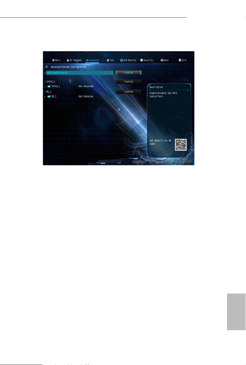
4.4.3 Storage Conguration
SATA Controller(s)
Enable/disable the SATA controllers.
FP6D4-P1
English
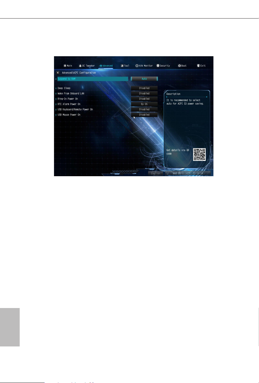
4.4.4 ACPI Conguration
Suspend to RAM
It is recommended to select auto for ACPI S3 power saving.
Deep Sleep
Congure deep sleep mode for power saving when the computer is shut down.
Wake From Onboard LAN
Allow the system to be waked up by onboard LAN.
Ring-In Power On
Allow the system to be waked up by onboard COM port modem Ring-In signals.
RTC Alarm Power On
Allow the system to be waked up by the real time clock alarm. Set it to By OS to let
it be handled by your operating system.
USB Keyboard/Remote Power On
English
Allow the system to be waked up by an USB keyboard or remote controller.
USB Mouse Power On
Allow the system to be waked up by an USB mouse.
28 29
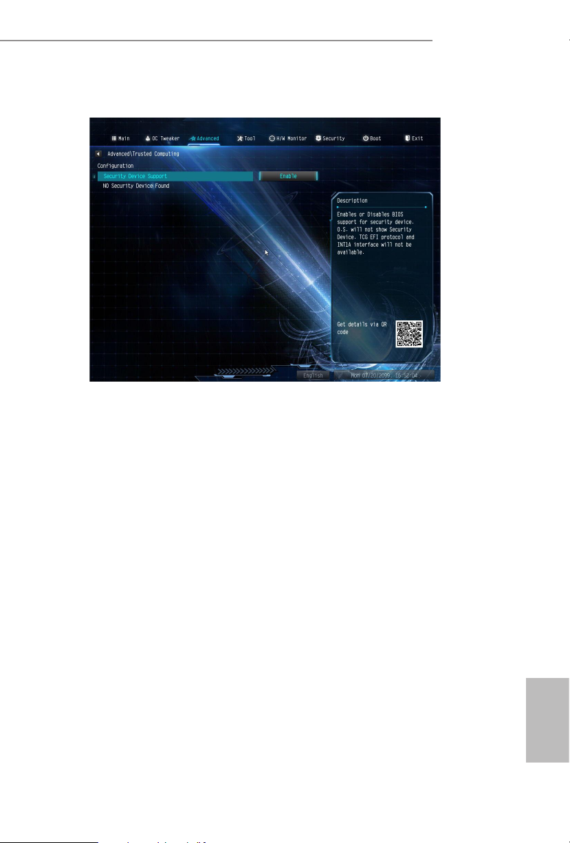
4.4.5 Trusted Computing
Security Device Support
Enable or disable BIOS support for security device.
FP6D4-P1
English
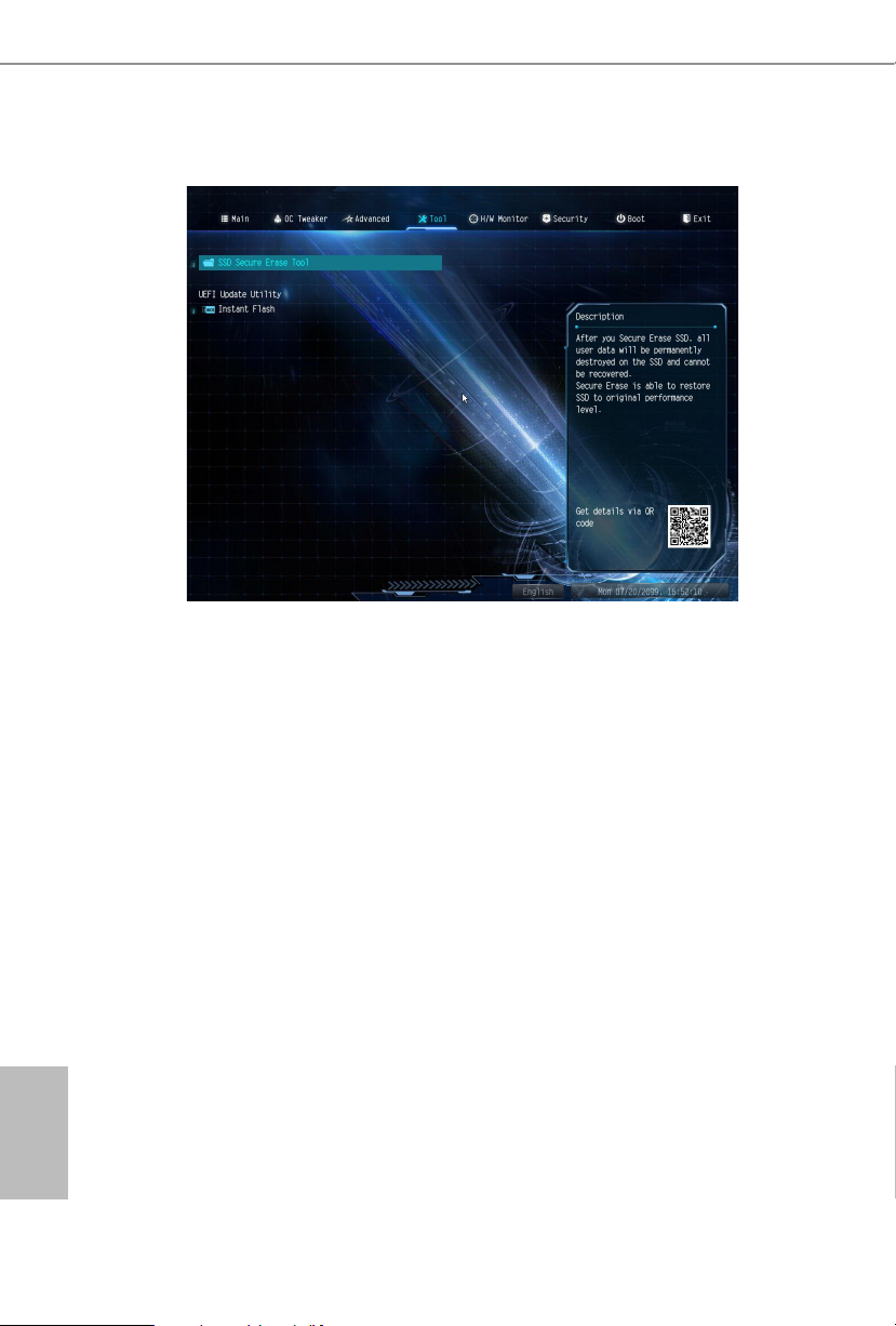
4.5 Tools
SSD Secure Erase Tool
Use this tool to securely erase SSD.
Instant Flash
Save UEFI les in your USB storage device and run Instant Flash to update your
UEFI.
English
30 31

4.6 Hardware Health Event Monitoring Screen
is section allows you to monitor the status of the hardware on your system,
including the parameters of the CPU temperature, motherboard temperature, fan
speed and voltage.
FP6D4-P1
CPU FAN1 Setting
Select a fan mode for CPU Fan 1, or choose Customize to set 5 CPU temperatures
and assign a respective fan speed for each temperature.
English
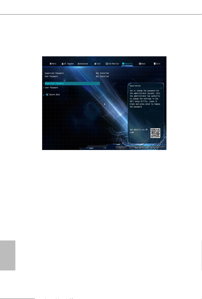
4.7 Security Screen
In this section you may set or change the supervisor/user password for the system.
You may also clear the user password.
Supervisor Password
Set or change the password for the administrator account. Only the administrator
has authority to change the settings in the UEFI Setup Utility. Leave it blank and
press enter to remove the password.
User Password
Set or change the password for the user account. Users are unable to change the
settings in the UEFI Setup Utility. Leave it blank and press enter to remove the
password.
Secure Boot
Enable to support Secure Boot.
English
32 33

4.8 Boot Screen
is section displays the available devices on your system for you to congure the
boot settings and the boot priority.
Fast Boot
Fast Boot minimizes your computer's boot time. In fast mode you may not boot
from an USB storage device.
FP6D4-P1
Boot From Onboard LAN
Allow the system to be waked up by the onboard LAN.
Setup Prompt Timeout
Congure the number of seconds to wait for the setup hot key.
Bootup Num-Lock
Select whether Num Lock should be turned on or o when the system boots up.
Full Screen Logo
Enable to display the boot logo or disable to show normal POST messages.
English
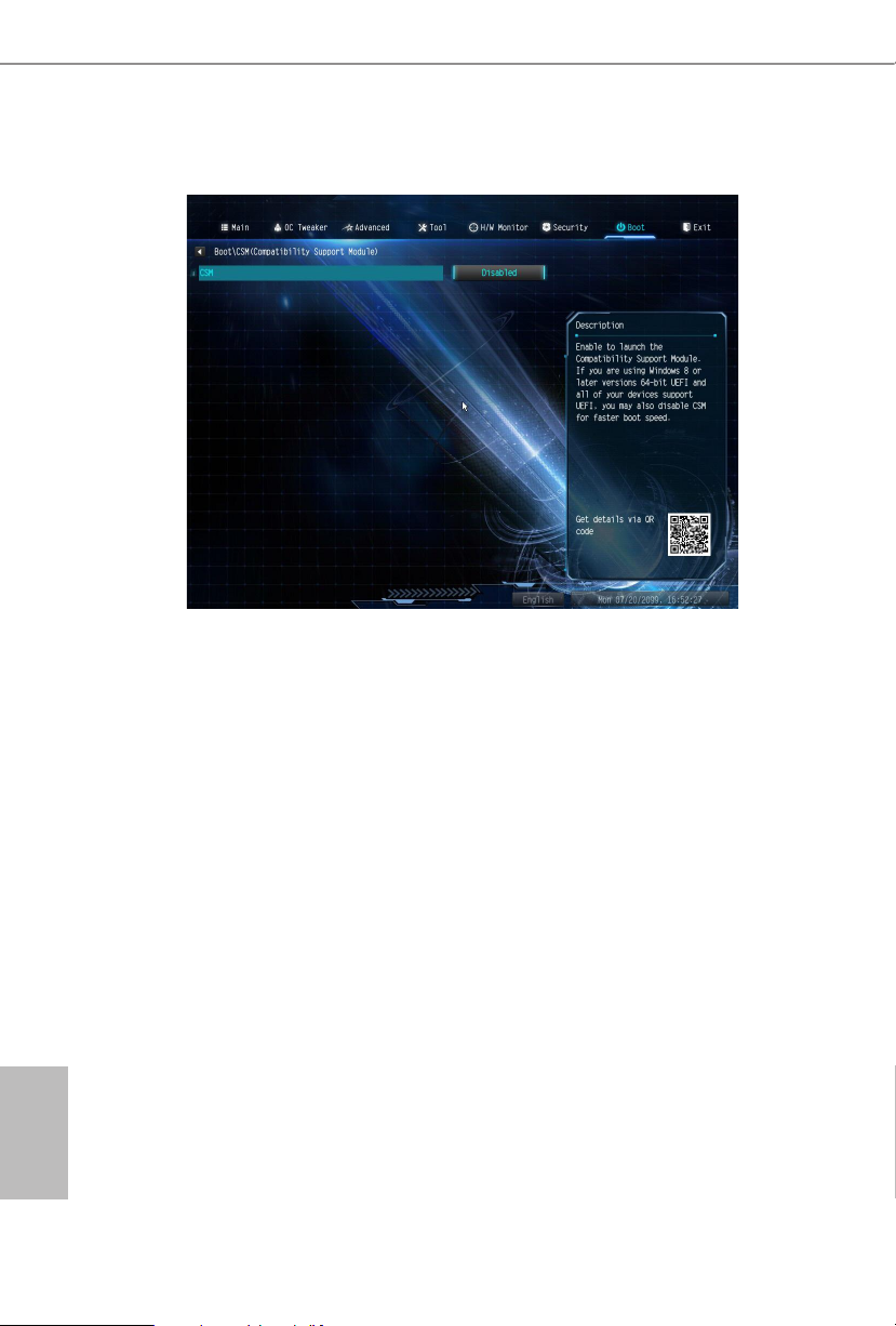
CSM (Compatibility Support Module)
CSM
Enable to launch the Compatibility Support Module. Please do not disable unless
you’re running a WHCK test.
Other PCI Device ROM Priority
For PCI devices other than Network. Mass storage or Video denes which OpROM-
to launch.
English
34 35

4.9 Exit Screen
Save Changes and Exit
When you select this option the following message, “Save conguration changes
and exit setup?” will pop out. Select [OK] to save changes and exit the UEFI SETUP
UTILITY.
FP6D4-P1
Discard Changes and Exit
When you select this option the following message, “Discard changes and exit
setup?” will pop out. Select [OK] to exit the UEFI SETUP UTILITY without saving
any changes.
Discard Changes
When you select this option the following message, “Discard changes?” will pop
out. Select [OK] to discard all changes.
Load UEFI BIOS Defaults
Load UEFI BIOS Default values for all the setup questions. e F9 key can be used
for this operation.
English

DECLARATION OF CONFORMITY
Per FCC Part 2 Section 2.1077(a)
Responsible Party Name: ASRock Incorporation
Address:
Phone/FaxNo:
hereby declares that the product
Product Name : Motherboard
13848 Magnolia Ave, Chino, CA91710
+1-909-590-8308/+1-909-590-1026
Model Number :
Conforms to the following specications:
FCC Part 15, Subpart B, Unintentional Radiators
Supplementary Information:
FP6D4-P1
is device complies with part 15 of the FCC Rules. Operation is subject to the
following two conditions: (1) is device may not cause harmful interference,
and (2) this device must accept any interference received, including interference
that may cause undesired operation.
James
Representative Person’s Name:
Signature :
Date :
May 12, 2017

EMC —Directive 2014/30/EU (from April 20th, 2016)
ڛ
☐
EU Declaration of Conformity
For the following equipment:
Motherboard
(Product Name)
FP6D4-P1
(Model Designation / Trade Name)
☐ EN 55022:2010/AC:2011 Class B EN 55024:2010/A1:2015
ڛ EN 55032:2012+AC:2013 Class B ڛڛ EN 61000-3-3:2013
ڛ EN 61000-3-2:2014
☐
LVD —Directive 2014/35/EU (from April 20th, 2016)
EN 60950-1 : 2011+ A2: 2013 ☐
ڛ RoHS — Directive 2011/65/EU
ڛ CE marking
EN 60950-1 : 2006/A12: 2011
(EU conformity marking)
 Loading...