


Version 1.1
Published May 2014
Copyright©2014 ASRock INC. All rights reserved.
Copyright Notice:
No part of this documentation may be reproduced, transcribed, transmitted, or
translated in any language, in any form or by any means, except duplication of
documentation by the purchaser for backup purpose, without written consent of
ASRock Inc.
Products and corporate names appearing in this documentation may or may not
be registered trademarks or copyrights of their respective companies, and are used
only for identication or explanation and to the owners’ benet, without intent to
infringe.
Disclaimer:
Specications and information contained in this documentation are furnished for
informational use only and subject to change without notice, and should not be
constructed as a commitment by ASRock. ASRock assumes no responsibility for
any errors or omissions that may appear in this documentation.
With respect to the contents of this documentation, ASRock does not provide
warranty of any kind, either expressed or implied, including but not limited to
the implied warranties or conditions of merchantability or tness for a particular
purpose.
In no event shall ASRock, its directors, ocers, employees, or agents be liable for
any indirect, special, incidental, or consequential damages (including damages for
loss of prots, loss of business, loss of data, interruption of business and the like),
even if ASRock has been advised of the possibility of such damages arising from any
defect or error in the documentation or product.
is device complies with Part 15 of the FCC Rules. Operation is subject to the following
two conditions:
(1) this device may not cause harmful interference, and
(2) this device must accept any interference received, including interference that
may cause undesired operation.
CALIFORNIA, USA ONLY
e Lithium battery adopted on this motherboard contains Perchlorate, a toxic substance
controlled in Perchlorate Best Management Practices (BMP) regulations passed by the
California Legislature. When you discard the Lithium battery in California, USA, please
follow the related regulations in advance.
“Perchlorate Material-special handling may apply, see www.dtsc.ca.gov/hazardouswaste/
perchlorate”
ASRock Website: http://www.asrock.com

e terms HDMI™ and HDMI High-Denition Multimedia Interface, and the HDMI
logo are trademarks or registered trademarks of HDMI Licensing LLC in the United
States and other countries.
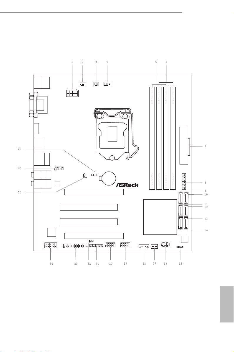
Motherboard Layout
Intel
H97
DDR 3_A2 (64 bit, 240- pin modu le)
DDR 3_A1 (64 bit, 240- pin modu le)
DDR 3_B2 (64 bit, 240- pin modu le)
DDR 3_B1 (64 bit, 240- pin modu le)
ATX12V1
CMO S
Bat ter y
Supe r
I/O
ATXP WR1
Top:
RJ-4 5
USB 3.0
T: USB 4
B: U SB5
Top:
Centr al/Bas s
Cente r:
REAR SPK
Top:
LINE IN
Cente r:
FRONT
Botto m:
Optic al
SPDIF
Botto m:
MIC IN
CLRCMO S1
1
1
SPEAKER1
HDLED RE SET
PLED PWRBTN
PANEL1
1
COM1
1
1
HD_AUD IO1
H97M Pro 4
SATA_0_1 SATA_2_3 SATA_4_5
CHA_FAN 1
CHA_FAN 2
PCI1
CPU_FAN 1
CPU_FAN 2
128M b
BIOS
HDMI 1
VGA 1
DVI 1
PCI2
USB 3.0
T:U SB2
B: USB3
Audio
CODEC
PCIE1
PCI Ex pr ess 3. 0
PCIE2
PWR_FAN 1
1
TPMS1
1
1
LPT1
CI1
RoH S
Fro nt US B 3.0
USB 2. 0
T: USB0
B: USB 1
Ps2
Keyb oard/
Mous e
1
USB10_ 11
TB1
USB6_7
1
USB8_9
1
H97M Pro4
English
1

No. Description
1 ATX 12V Power Connector (ATX12V1)
2 Power Fan Connector (PWR_FAN1)
3 CPU Fan Connector (CPU_FAN2)
4 CPU Fan Connector (CPU_FAN1)
5 2 x 240-pin DDR3 DIMM Slots (DDR3_A1, DDR3_B1)
6 2 x 240-pin DDR3 DIMM Slots (DDR3_A2, DDR3_B2)
7 ATX Power Connector (ATXPWR1)
8 USB 3.0 Header (USB10_11)
9 SATA3 Connector (SATA_4)
10 SATA3 Connector (SATA_5)
11 SATA3 Connector (SATA_2)
12 SATA3 Connector (SATA_3)
13 SATA3 Connector (SATA_1)
14 SATA3 Connector (SATA_0)
15 Chassis Speaker Header (SPEAKER1)
16 System Panel Header (PANEL1)
17 Chassis Fan Connector (CHA_FAN1)
18 underbolt AIC Connector (TB1)
19 USB 2.0 Header (USB8_9)
20 USB 2.0 Header (USB6_7)
21 TPM Header (TPMS1)
22 Chassis Intrusion Header (CI1)
23 Print Port Header (LPT1)
24 COM Port Header (COM1)
25 Chassis Fan Connector (CHA_FAN2)
26 Front Panel Audio Header (HD_AUDIO1)
27 Clear CMOS Jumper (CLRCMOS1)
English
2
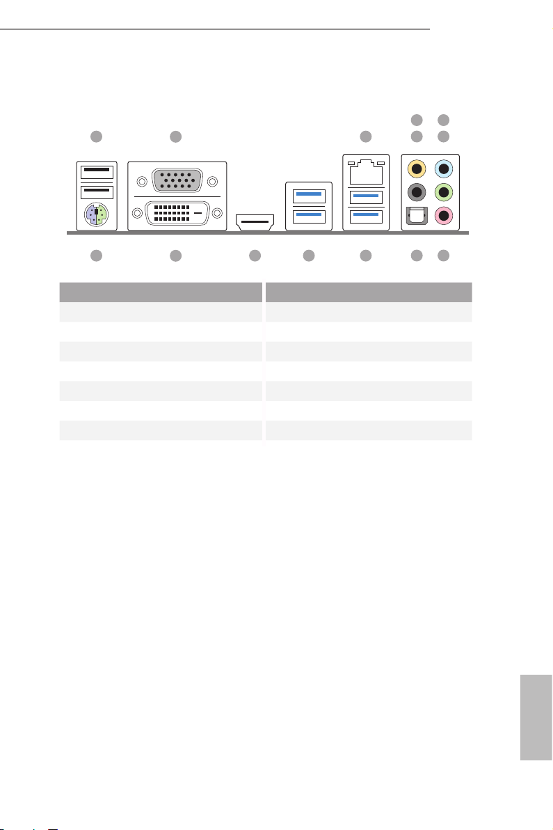
I/O Panel
1 3
2
H97M Pro4
476
5
14 101112
No. Description No. Description
1 USB 2.0 Ports (USB01) 8 Microphone (Pink)
2 D-Sub Port 9 Optical SPDIF Out Port
3 LAN RJ-45 Port* 10 USB 3.0 Ports (USB45)
4 Central / Bass (Orange) 11 USB 3.0 Ports (USB23)
5 Rear Speaker (Black) 12 HDMI Port
6 Line In (Light Blue) 13 DVI-D Port
7 Front Speaker (Lime)** 14 PS/2 Mouse/Keyboard Port
13
89
English
3
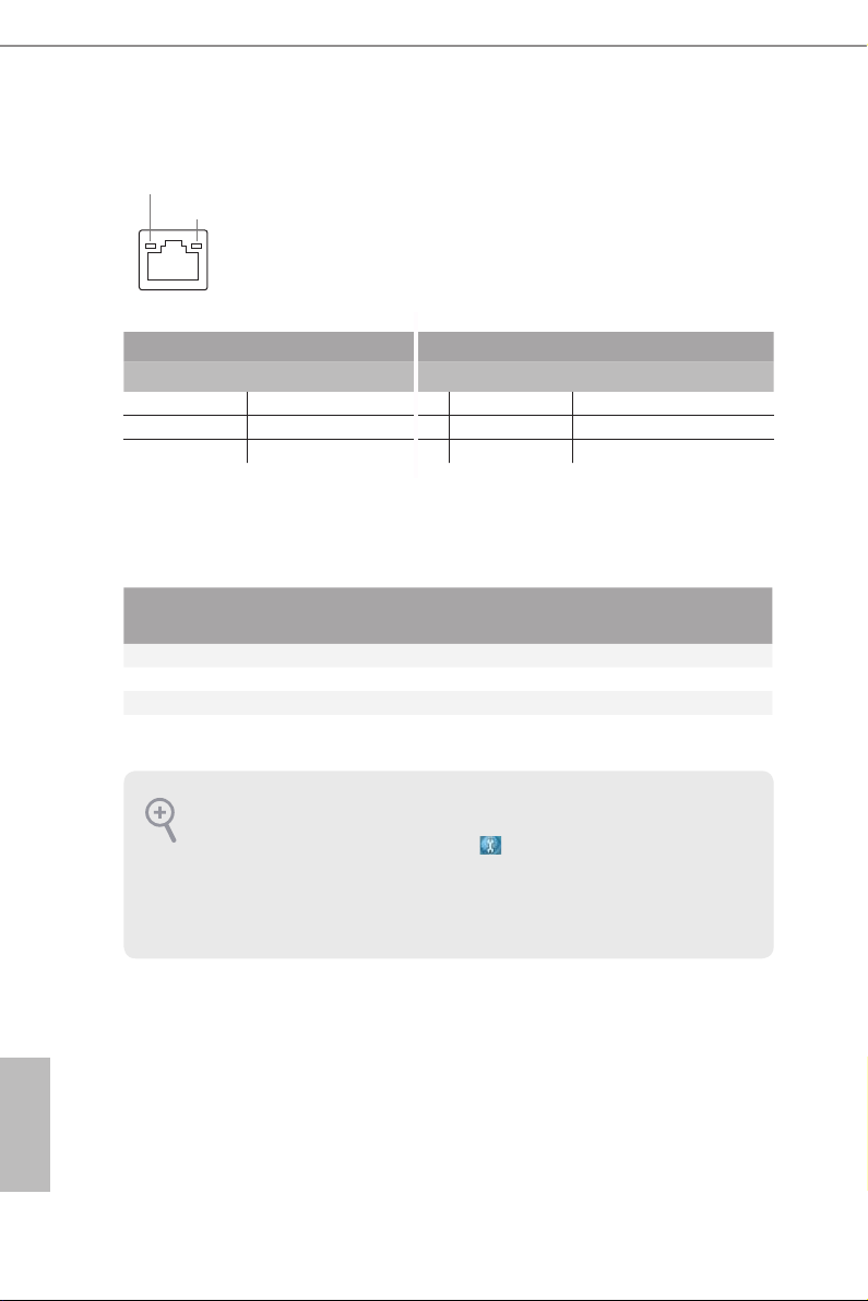
* ere are two LEDs on each LAN port. Please refer to the table below for the LAN port LED indications.
ACT/LINK L ED
SPEED LE D
LAN Por t
Activity / Link LED Speed LED
Status Description Status Description
O No Link O 10Mbps connection
Blinking Data Activity Orange 100Mbps connection
On Link Green 1Gbps connection
** If you use a 2- channel speaker, plea se connect the speake r’s plug into “Front Speaker Jack”. See the table below
for connection d etails in accordance w ith the type of speaker you use.
English
Audio Output
Channels
Front Speaker
(No. 7)
Rear Speaker
(No. 5)
Central / Bass
(No. 4)
2 V -- -- --
4 V V -- --
6 V V V --
8 V V V V
To enable Multi-Streaming, you need to connect a front panel audio cable to the front
panel audio header. Aer restarting your computer, you will nd the “Mixer” tool
on your system. Please select “Mixer ToolBox” , click “Enable playback multistreaming”, and click “ok”. Choose “2CH”, “4CH”, “6CH”, or “8CH” and then you are
allowed to select “Realtek HDA Pr imary output” to use the Rear Speaker, Central/
Bass, and Front Speake r, or select “Realtek HDA Audio 2nd output” to use the front
panel audio.
Line In
(No. 6)
4

Chapter 1 Introduction
ank you for purchasing ASRock H97M Pro4 motherboard, a reliable
motherboard produced under ASRock’s consistently stringent quality control.
It delivers excellent performance with robust design conforming to ASRock’s
commitment to quality and endurance.
Becau se the motherboard specications and the BIOS soware might be updated, the
content of this manual will be subject to change without notice. In ca se any modications of this manual occur, the updated version will be available on ASRock’s website
without further notice. If you require technical suppor t related to this motherboard,
please visit our website for spe cic information about the model you are using. You
may nd the l atest VGA cards and CPU support list on ASRock’s website a s well.
ASRock website http://www.asrock.com.
1.1 Package Contents
ASRock H97M Pro4 Motherboard (Micro ATX Form Factor)
•
ASRock H97M Pro4 Quick Installation Guide
•
ASRock H97M Pro4 Support CD
•
2 x Serial ATA (SATA) Data Cables (Optional)
•
1 x I/O Panel Shield
•
H97M Pro4
English
5

1.2 Specications
Platform
CPU
Chipset
Memory
Expansion
Slot
Micro ATX Form Factor
•
All Solid Capacitor design
•
High Density Glass Fabric PCB
•
Supports 5th Generation, New 4th and 4th Generation Intel®
•
CoreTM i7/i5/i3/Pentium®/Celeron® Processors (Socket 1150)
Digi Power design
•
4 Power Phase design
•
Supports Intel® Turbo Boost 2.0 Technology
•
Intel® H97
•
Supports Intel® Small Business Advantage 2.0
•
Dual Channel DDR3 Memory Technology
•
4 x DDR3 DIMM Slots
•
Supports DDR3 1600/1333/1066 non-ECC, un-buered
•
memory
Max. capacity of system memory: 32GB (see CAUTION)
•
Supports Intel® Extreme Memory Prole (XMP) 1.3 / 1.2
•
1 x PCI Express 3.0 x16 Slot (PCIE1: x16 mode)
•
1 x PCI Express 2.0 x16 Slot (PCIE2: x4 mode)
•
2 x PCI Slots
•
Supports AMD Quad CrossFireXTM and CrossFireXTM
•
English
6
Graphics
Intel® HD Graphics Built-in Visuals and the VGA outputs can
•
be supported only with processors which are GPU integrated.
Supports Intel® HD Graphics Built-in Visuals : Intel® Quick
•
Sync Video with AVC, MVC (S3D) and MPEG-2 Full
HW Encode1, Intel® InTruTM 3D, Intel® Clear Video HD
Technology, Intel® InsiderTM, Intel® HD Graphics 4400/4600
Pixel Shader 5.0, DirectX 11.1
•
Max. shared memory 1792MB
•
ree graphics output options: D-Sub, DVI-D and HDMI
•
Supports Triple Monitor
•
Supports HDMI with max. resolution up to 1920x1200 @
•
60Hz

Audio
LAN
Supports DVI-D with max. resolution up to 1920x1200 @
•
60Hz
Supports D-Sub with max. resolution up to 1920x1200 @
•
60Hz
Supports Auto Lip Sync, Deep Color (12bpc), xvYCC and
•
HBR (High Bit Rate Audio) with HDMI Port (Compliant
HDMI monitor is required)
Supports HDCP with DVI-D and HDMI Ports
•
Supports Full HD 1080p Blu-ray (BD) playback with DVI-D
•
and HDMI Ports
7.1 CH HD Audio with Content Protection (Realtek ALC892
•
Audio Codec)
Premium Blu-ray Audio support
•
Supports Surge Protection (ASRock Full Spike Protection)
•
ELNA Audio Caps
•
Gigabit LAN 10/100/1000 Mb/s
•
Giga PHY Intel® I218V
•
Supports Intel® Remote Wake Technology
•
Supports Wake-On-LAN
•
Supports Lightning/ESD Protection (ASRock Full Spike
•
Protection)
Supports Energy Ecient Ethernet 802.3az
•
Supports PXE
•
H97M Pro4
Rear Panel
I/O
1 x PS/2 Mouse/Keyboard Port
•
1 x D-Sub Port
•
1 x DVI-D Port
•
1 x HDMI Port
•
1 x Optical SPDIF Out Port
•
2 x USB 2.0 Ports (Supports ESD Protection (ASRock Full
•
Spike Protection))
4 x USB 3.0 Ports (Supports ESD Protection (ASRock Full
•
Spike Protection))
1 x RJ-45 LAN Port with LED (ACT/LINK LED and SPEED
•
LED)
HD Audio Jacks: Rear Speaker / Central / Bass / Line in /
•
Front Speaker / Microphone
English
7

Storage
Connector
BIOS
Feature
6 x SATA3 6.0 Gb/s Connectors, support RAID (RAID 0,
•
RAID 1, RAID 5, RAID 10, Intel Rapid Storage Technology
13 and Intel Smart Response Technology), NCQ, AHCI and
Hot Plug
1 x Print Port Header
•
1 x COM Port Header
•
1 x Chassis Intrusion Header
•
1 x TPM Header
•
2 x CPU Fan Connectors (1 x 4-pin, 1 x 3-pin)
•
2 x Chassis Fan Connectors (1 x 4-pin, 1 x 3-pin)
•
1 x Power Fan Connector (3-pin)
•
1 x 24 pin ATX Power Connector
•
1 x 8 pin 12V Power Connector
•
1 x Front Panel Audio Connector
•
1 x underbolt AIC Connector
•
2 x USB 2.0 Headers (Support 4 USB 2.0 ports) (Supports ESD
•
Protection (ASRock Full Spike Protection))
1 x USB 3.0 Header (Supports 2 USB 3.0 ports) (Supports ESD
•
Protection (ASRock Full Spike Protection))
128Mb AMI UEFI Legal BIOS with multilingual GUI support
•
ACPI 1.1 Compliant wake up events
•
SMBIOS 2.3.1 support
•
CPU, DRAM, PCH 1.05V, PCH 1.5V Voltage multi-adjust-
•
ment
English
8
Hardware
Monitor
OS
CPU/Chassis temperature sensing
•
CPU/Chassis/Power Fan Tachometer
•
CPU/Chassis Quiet Fan (Auto adjust chassis fan speed by
•
CPU temperature)
CPU/Chassis Fan multi-speed control
•
CASE OPEN detection
•
Voltage monitoring: +12V, +5V, +3.3V, CPU Vcore
•
Microso® Windows® 10 64-bit / 8.1 32-bit / 8.1 64-bit / 8 32-bit /
•
8 64-bit / 7 32-bit / 7 64-bit
FCC, CE, WHQL
Certications
* For detailed product information, please visit our website: http://www.asrock.com
Please realize that the re is a certain risk involved with overclocking, including adjusting the setting in the BIOS, applying Untied Ove rclocking Technology, or using thirdparty overclocking tools. Overclocking may aect your system’s stability, or even cause
damage to the components and devices of your system. It should be done at your own
risk and expense. We are not responsible for possible damage cau sed by overclocking.
Due to limitation, the actual memory size may be less than 4GB for the reservation
for system usage under Windows® 32-bit operating systems. Windows® 64-bit operating systems do not have such limitations. You can use ASRock XFast RAM to utilize
the memory that Windows® cannot use.
•
ErP/EuP ready (ErP/EuP ready power supply is required)
•
H97M Pro4
English
9

Chapter 2 Installation
is is a Micro ATX form factor motherboard. Before you install the motherboard,
study the conguration of your chassis to ensure that the motherboard ts into it.
Pre-installation Precautions
Take note of the following precautions before you install motherboard components
or change any motherboard settings.
Make sure to unplug the power cord before installing or removing the motherboard
•
components. Failure to do so may cause physical injuries and damages to motherboard
components.
In order to avoid damage from static electricity to the motherboard’s components,
•
NEVER place your motherboard directly on a carpet. Also remember to use a grounded
wrist strap or touch a safety grounded object before you handle the components.
Hold components by the edges and do not touch the ICs.
•
Whenever you uninstall any components, place them on a grounded anti-static pad or
•
in the bag that comes with the components.
When placing screws to secure the motherboard to the chassis, please do not over-
•
tighten the screws! Doing so may damage the motherboard.
English
10
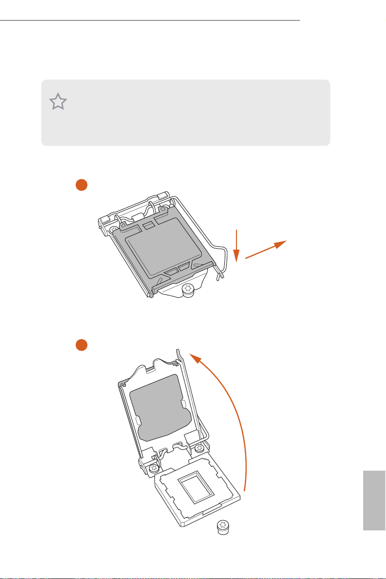
2.1 Installing the CPU
1. Before you inser t the 1150-Pin CPU into the socket, please check if the PnP cap is on
the socket, if the CPU surfa ce is unclean, or if there are any bent pins in the socket.
Do not force to insert the CPU into the socket if above situation is found. Otherwise,
the CPU will be seriously damaged .
2. Unplug all power cables before installing the CPU.
1
H97M Pro4
A
B
2
English
11
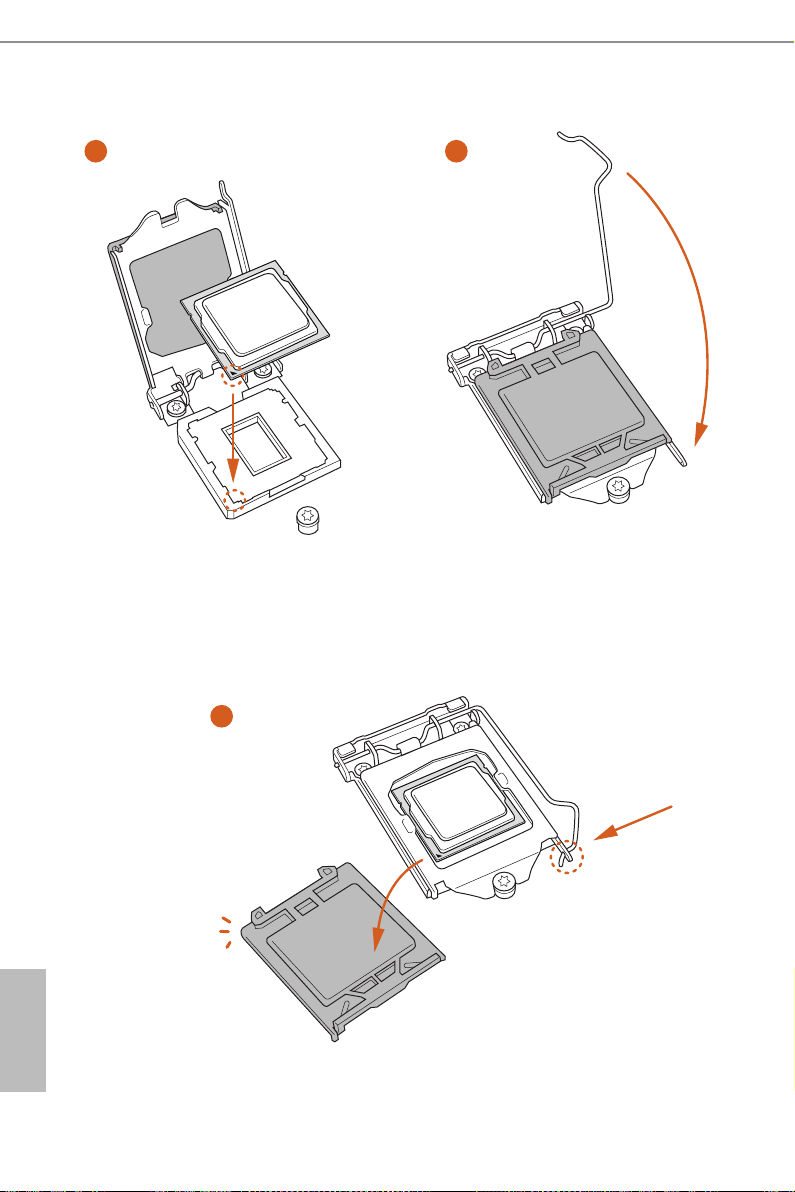
3
5
4
English
12

Please save and replace the cover if the processor i s removed. e cover must be placed
if you wish to retur n the motherboard for aer service.
H97M Pro4
13
English
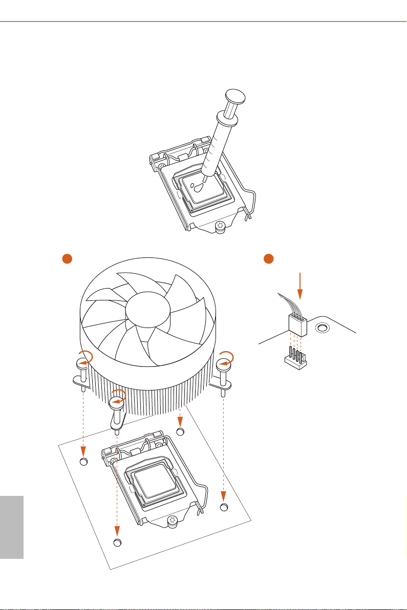
2.2 Installing the CPU Fan and Heatsink
1 2
English
14
N
FA
_
U
P
C
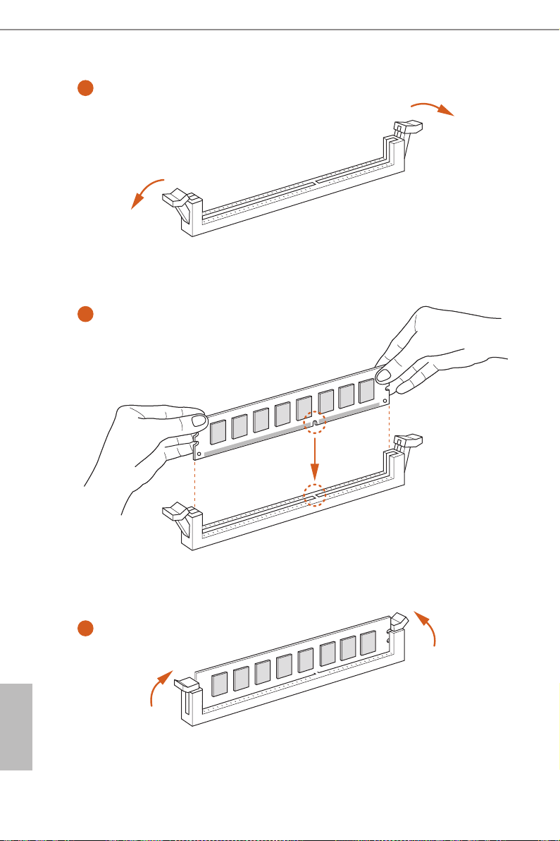
2.3 Installing Memory Modules (DIMM)
is motherboard provides four 240-pin DDR3 (Double Data Rate 3) DIMM slots,
and supports Dual Channel Memory Technology.
1. For dual channel conguration, you always need to install identical (the same
brand, speed , size and chip-type) DDR3 DIMM pairs.
2. It is unable to activate Dual Channel Memory Technology with only one or three
memory module installed.
3. It is not allowed to install a DDR or DDR2 memory module into a DDR3 slot;
otherwise, this motherboard and DIMM may be damaged.
Dual Channel Memory Conguration
Priority DDR3_A1 DDR3_A2 DDR3_B1 DDR3_B2
1 Populated Populated
2 Populated Populated
3 Populated Populated Populated Populated
H97M Pro4
e DIMM only ts in one correct orientation. It will cause permanent damage to
the mothe rboard and the DIMM if you force the DIMM into the slot at incor rect
orientation.
English
15
1
2
English
16
3

2.4 Expansion Slots (PCI and PCI Express Slots)
ere are 2 PCI slots and 2 PCI Express slots on the motherboard.
Before installing an ex pansion card, please make sure that the power supply is
switched o or the power cord is unplugged. Plea se read the documentation of the
expan sion card and make necessary hardware settings for the card before you start
the installation.
PCI slots:
e PCI1 and PCI2 slots are used to install expansion cards that have 32-bit PCI
interface.
PCIe slots:
PCIE1 (PCIe 3.0 x16 slot) is used for PCI Express x16 lane width graphics cards.
PCIE2 (PCIe 2.0 x16 slot) is used for PCI Express x4 lane width graphics
cards.
PCIe Slot Congurations
PCIE1 PCIE2
H97M Pro4
Single Graphics Card x16 N/A
Two Graphics Cards in
CrossFireXTM Mode
For a better ther mal environment, please connect a chassi s fan to the motherboard’s
chassis fan connector (CHA_ FAN1 or CHA_ FAN2) when using multiple graphics
cards.
x16 x4
English
17
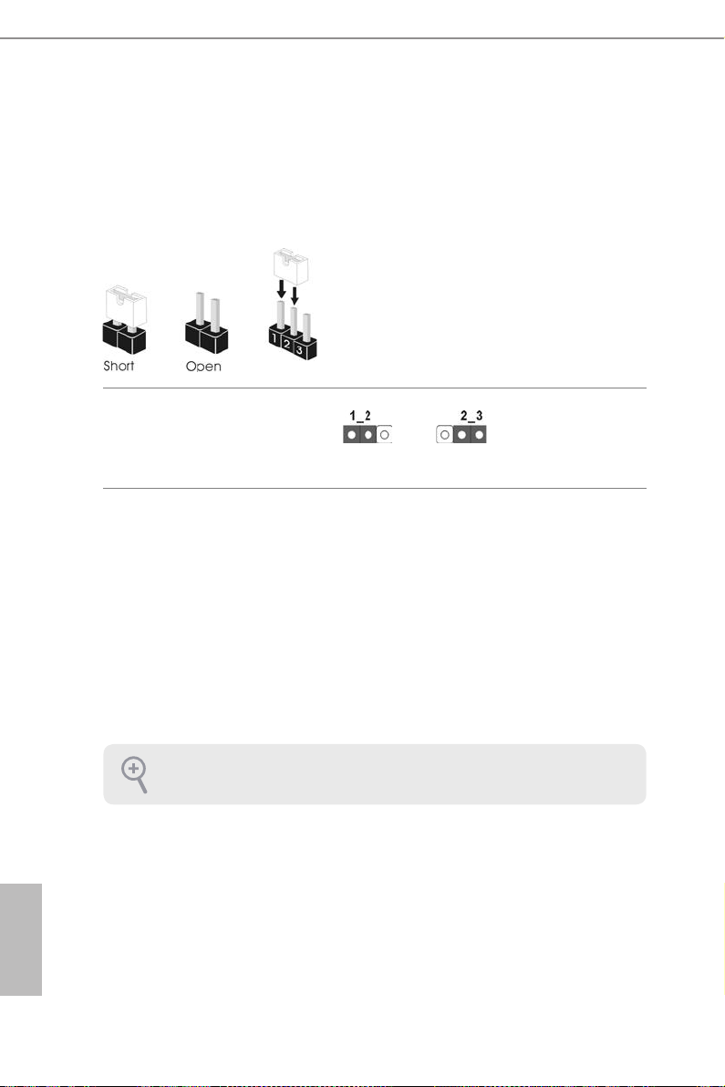
2.5 Jumpers Setup
e illustration shows how jumpers are setup. When the jumper cap is placed on
the pins, the jumper is “Short”. If no jumper cap is placed on the pins, the jumper
is “Open”. e illustration shows a 3-pin jumper whose pin1 and pin2 are “Short”
when a jumper cap is placed on these 2 pins.
Clear CMOS Jumper
(CLRCMOS1)
(see p.1, No. 27)
CLRCMOS1 allows you to clear the data in CMOS. To clear and reset the system
parameters to default setup, please turn o the computer and unplug the power
cord from the power supply. Aer waiting for 15 seconds, use a jumper cap to
short pin2 and pin3 on CLRCMOS1 for 5 seconds. However, please do not clear
the CMOS right aer you update the BIOS. If you need to clear the CMOS when
you just nish updating the BIOS, you must boot up the system rst, and then shut
it down before you do the clear-CMOS action. Please be noted that the password,
date, time, and user default prole will be cleared only if the CMOS battery is
removed.
Clear CMOSDefault
English
18
If you clear the CMOS, the case open may be detec ted. Please adjust the BIOS option
“Clear Status” to clear the record of previou s chassis intrusion status.
2.6 Onboard Headers and Connectors
Onboard headers and connectors are NOT jumpers. Do NOT place jumper caps over
these headers and connectors. Placing jumper caps over the headers and connectors
will cause permanent damage to the motherboard.
H97M Pro4
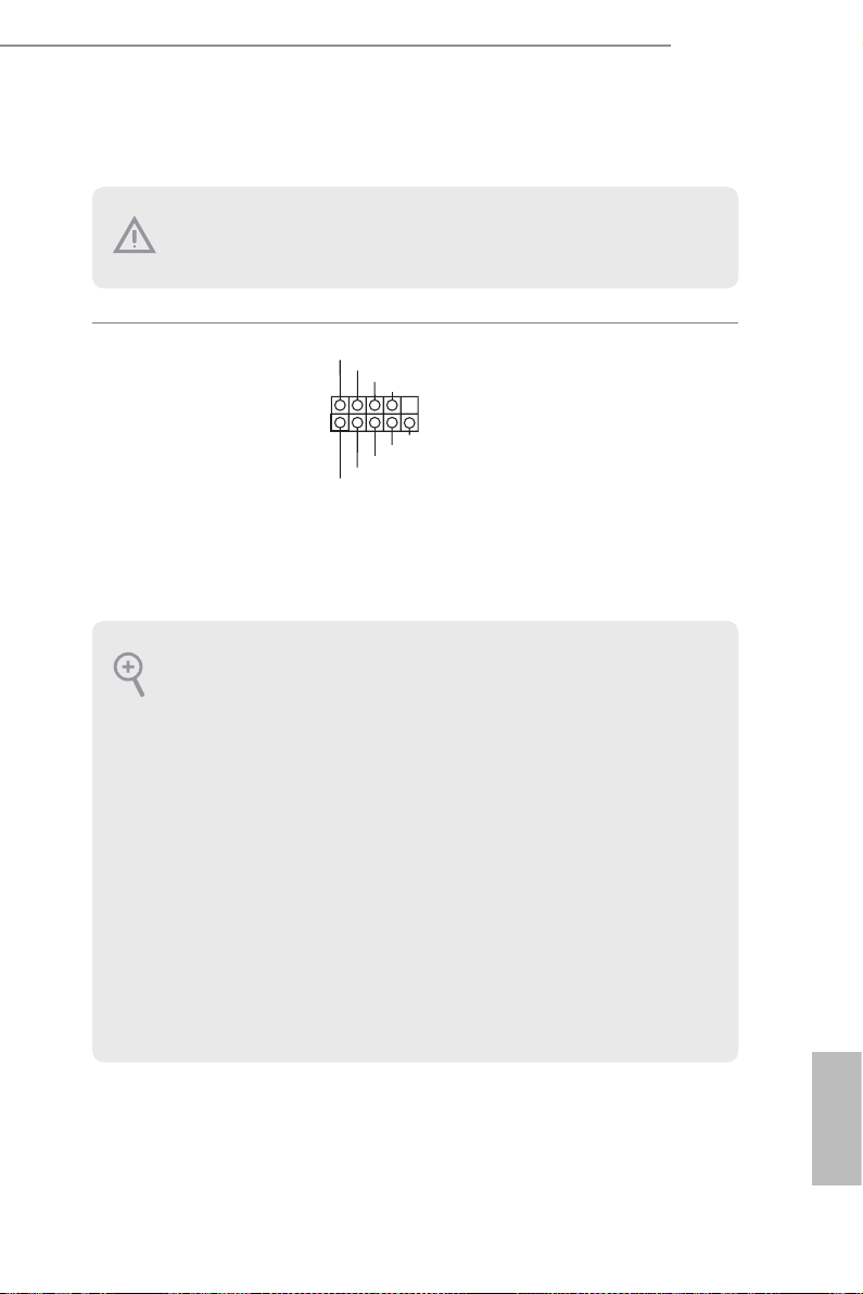
System Panel Header
(9-pin PANEL1)
(see p.1, No. 16)
PWRBTN (Power Switch):
Connec t to the power switch on the chassi s front panel. You may congure the way to
turn o your system using the power switch.
RESET (Reset Switch):
Connec t to the reset switch on the chassis front panel. Press the reset sw itch to restart
the computer if the compute r freezes and fails to perform a normal restart.
PLED (Syste m Power LED):
Connec t to the power status indicator on the chassis front panel. e LED i s on when
the system is ope rating. e LED keeps blinking when the system i s in S1/S3 sleep state.
e LED is o when the system is in S4 sleep state or powered o (S5).
HDLED (Ha rd Drive Activity LED):
Connec t to the hard drive activity LED on the chassis front panel. e LED is on when
the hard dr ive is reading or writing data.
e front panel design may dier by chassis. A front panel module mainly consists
of power switch, reset switch, power LED, hard dr ive activity LED, speak er and etc.
When connecting your chassis front panel module to this head er, make sure the wire
assig nments and the pin assig nments are matched correctly.
1
PLE D+
PLE D-
HDL ED-
HDL ED+
PWR BTN #
GND
RES ET#
GND
GND
Connect the power
switch, reset switch and
system status indicator on
the chassis to this header
according to the pin
assignments below. Note
the positive and negative
pins before connecting
the cables.
19
English

Serial ATA3 Connectors
(SATA_0:
see p.1, No. 14)
(SATA_1:
see p.1, No. 13)
(SATA_2:
see p.1, No. 11)
(SATA_3:
see p.1, No. 12)
(SATA_4:
see p.1, No. 9)
(SATA_5:
see p.1, No. 10)
SATA_4SATA_0 SATA_2
ese six SATA3
connectors support SATA
data cables for internal
SATA_5SATA_1 SATA_3
storage devices with up to
6.0 Gb/s data transfer rate.
English
USB 2.0 Headers
(9-pin USB6_7)
(see p.1, No. 20)
(9-pin USB8_9)
(see p.1, No. 19)
USB 3.0 Header
(19-pin USB10_11)
(see p.1, No. 8)
Front Panel Audio Header
(9-pin HD_AUDIO1)
(see p.1, No. 26)
USB _PW R
1
USB _PW R
IntA _PA_S SRX-
IntA _PA_S SRX+
IntA _PA_S STX-
IntA _PA_S STX+
IntA _PA_D -
IntA _PA_D +
1
P-
P-
Vbus
GND
GND
GND
PRE SEN CE#
MIC 2_R
MIC 2_L
P+
P+
1
MIC _RE T
OUT 2_R
GND
DUM MY
GND
VbusVbus
IntA _PB_ SSRX -
IntA _PB_ SSRX +
GND
IntA _PB_ SSTX -
IntA _PB_ SSTX +
GND
IntA _PB_ D-
IntA _PB_ D+
Dumm y
OUT _RE T
OUT 2_L
J_S ENS E
Besides two USB 2.0 ports
on the I/O panel, there
are two headers on this
motherboard. Each USB
2.0 header can support
two ports.
Besides four USB 3.0
ports on the I/O panel,
there is one header on this
motherboard. Each USB
3.0 header can support
two ports.
is header is for
connecting audio devices
to the front audio panel.
20

1. High Denition Audio supports Jack Sensing, but the panel wire on the chassis must
GND
+12 V
FAN_ SPE ED
FAN_S PEE D
FAN_S PEE D_CO NTR OL
GND
+12V
1 2 3 4
GND
FAN_ VOLTAG E
FAN_ SPE ED
suppor t HDA to function correctly. Please follow the instructions in our manual and
chassis manual to install your system.
2. If you use an AC’97 audio panel, please install it to the f ront panel audio header by
the steps below:
A. Connect Mic_IN (MIC) to MIC2_ L.
B. Conne ct Audio_R (RIN) to OUT2_R and Audio_ L (LIN) to OUT2_ L.
C. Connect Ground (GND) to Ground (GND).
D. MIC_ RET and OUT_RET are for the HD audio panel only. You don’t need to
connect them for the AC’97 audio panel.
E. To activate the front mic, go to the “FrontMic” Tab in the Realtek Control panel
and adju st “Recording Volume”.
H97M Pro4
Chassis Speaker Header
(4-pin SPEAKER1)
(see p.1, No. 15)
Chassis and Power Fan
Connectors
(4-pin CHA_FAN1)
(see p.1, No. 17)
(3-pin CHA_FAN2)
(see p.1, No. 25)
(3-pin PWR_FAN1)
(see p.1, No. 2)
DUM MY
1
+5V
SPE AKE R
DUM MY
Please connect the chassis
speaker to this header.
Please connect fan cables
to the fan connectors and
match the black wire to
the ground pin.
English
21

CPU Fan Connectors
FAN_S PEE D
FAN_S PEE D_CO NTR OL
GND
+12V
1 2 3 4
GND
FAN_ VOLTAG E
FAN_ SPE ED
(4-pin CPU_FAN1)
(see p.1, No. 4)
(3-pin CPU_FAN2)
(see p.1, No. 3)
ATX Power Connector
(24-pin ATXPWR1)
(see p.1, No. 7)
is motherboard provides a 4-Pin CPU fan
(Quiet Fan) connector.
If you plan to connect a
3-Pin CPU fan, please
connect it to Pin 1-3.
12
24
is motherboard provides a 24-pin ATX power
connector. To use a 20-pin
ATX power supply, please
plug it along Pin 1 and Pin
1
13
13.
English
ATX 12V Power
Connector
(8-pin ATX12V1)
(see p.1, No. 1)
underbolt AIC
Connector
(5-pin TB1)
(see p.1, No. 18)
Serial Port Header
(9-pin COM1)
(see p.1, No. 24)
8 5
4 1
RRXD 1
DDTR #1
DDSR #1
CCTS #1
1
RRTS #1
GND
TTXD 1
DDCD #1
is motherboard provides an 8-pin ATX 12V
power connector. To use a
4-pin ATX power supply,
please plug it along Pin 1
and Pin 5.
Please connect a 5-pin signal
cable (GPIO cable) to this
connector when you install
a underboltTM add-in card
(AIC).
is COM1 header
supports a serial port
module.
RRI# 1
22

H97M Pro4
1
Chassis Intrusion Header
(2-pin CI1)
(see p.1, No. 22)
TPM Header
(17-pin TPMS1)
(see p.1, No. 21)
Print Port Header
(25-pin LPT1)
(see p.1, No. 23)
1
AFD #
STB #
ERR OR#
PIN I T#
SPD 1
SPD 0
SLI N #
SPD 2
SPD 3
SPD 4
1
SPD 5
Sig nal
SPD 6
GND
GND
SPD 7
ACK #
BUS Y
is motherboard
supports CASE OPEN
detection feature that
detects if the chassis cove
has been removed. is
feature requires a chassis
with chassis intrusion
detection design.
is connector supports
Trusted Platform Module
(TPM) system, which can
securely store keys, digital
certicates, passwords,
and data. A TPM system
also helps enhance
network security, protects
digital identities, and
ensures platform integrity.
is is an interface
for print port cable
that allows convenient
connection of printer
PE
SLC T
devices.
English
23

1 Einleitung
Vielen Dank für den Kauf unseres ASRock H97M Pro4, eines zuverlässigen
Motherboards, das nach ASRocks strengen Qualitätsrichtlinien gefertigt wurde. Es
liefert ausgezeichnete Leistung mit robustem Design, das ASRocks Streben nach
Qualität und Beständigkeit erfüllt.
Da die technischen Daten des Motherboards sowie die BIOS-Soware aktualisiert werden
können, kann der Inhalt dieser Anleitung ohne Ankündigung geändert werden. Falls diese
Anleitung irgendwelchen Änderungen unterliegt, wird die aktualisierte Version ohne weitere Hinweise auf der ASRock-Webseite zur Verfügung gestellt. Sollten Sie technische Hilfe
in Bezug auf dieses Motherboard benötigen, erhalten Sie auf unserer Webseite spezischen
Informationen über das von Ihnen verwendete Modell. Auch nden Sie eine aktuelle Liste
unterstützter VGA-Karten und Prozessoren auf der ASRock-Webseite: ASRock-Website
http://www.asrock.com.
1.1 Lieferumfang
• ASRock H97M Pro4-Motherboard (Micro-ATX-Formfaktor)
• ASRock H97M Pro4 – Schnellinstallationsanleitung
• ASRock H97M Pro4-Unterstützungs-CD
• 2 x Serial-ATA- (SATA) Datenkabel (optional)
• 1 x E/A-Blendenabschirmung
Deutsch
24

1.2 Technische Daten
H97M Pro4
Plattform
Prozessor
Chipsatz
Speicher
Erweiterungssteckplatz
• Micro-ATX-Formfaktor
• Vollständig solides Kondensatordesign
• Leiterplatte mit hochdichtem Glasgewebe
• Unterstützt Intel® CoreTM i7/i5/i3/Pentium®/Celeron®-
Prozessoren (Sockel 1150) der 5., 4. und neuen 4. Generation
• Digipower-Design
• 4-Leistungsphasendesign
• Unterstützt Intel® Turbo Boost 2.0-Technologie
• Intel® H97
• Unterstützt Intel® Small Business Advantage 2.0
• Dualkanal-DDR3-Speichertechnologie
• 4 x DDR3-DIMM-Steckplätze
• Unterstützt DDR3 1600/1333/1066 non-ECC, ungepuerter
Speicher
• Systemspeicher, max. Kapazität: 32 GB (siehe ACHTUNG)
• Unterstützt Intel® Extreme Memory Prole (XMP)1.3/1.2
• 1 x PCI-Express 3.0-x16-Steckplatz (PCIE1:x16-Modus)
• 1 x PCI-Express 2.0-x16-Steckplatz (PCIE2:x4-Modus)
• 2 x PCI-Steckplätze
• Unterstützt AMD Quad CrossFireXTM und CrossFireXTM
Grakkarte
• Integrierte Intel® HD Graphics-Visualisierung und VGAAusgänge können nur mit Prozessoren unterstützt werden, die
GPU-integriert sind.
• Unterstützt integrierte Intel® HD Graphics-Visualisierung:
Intel® Quick Sync Video mit AVC, MVC (S3D) und MPEG2 Full HW Encode1, Intel® InTruTM 3D, Intel® Clear Video HD
Technology, Intel® InsiderTM, Intel® HD Graphics 4400/4600
• Pixel Shader 5.0, DirectX 11.1
• Max. geteilter Speicher: 1792 MB
• Drei Grakkarten-Ausgangsoptionen: D-Sub, DVI-D und
HDMI
Deutsch
25

• Unterstützt drei Monitore
• Unterstützt HDMI mit maximaler Auösung von 1920 x 1200
bei 60 Hz
• Unterstützt DVI-D mit maximaler Auösung von 1920 x 1200
bei 60 Hz
• Unterstützt D-Sub mit maximaler Auösung von 1920 x 1200
bei 60 Hz
• Unterstützt Auto-Lippensynchronizität, hohe Farbtiefe (12
bpc), xvYCC und HBR (Audio mit hoher Bitrate) mit HDMIPort (konformer HDMI-Monitor erforderlich)
• Unterstützt HDCP mit DVI-D- und HDMI-Ports
• Unterstützt Blu-ray- (BD) Wiedergabe (Full HD/1080p) mit
DVI-D- und HDMI-Ports
Deutsch
Audio
LAN
Rückblende,
E/A
• 7.1-Kanal-HD-Audio mit Inhaltsschutz (Realtek ALC892Audiocodec)
• Erstklassige Blu-ray-Audiounterstützung
• Unterstützt Überspannungsschutz (ASRock Full Spike
Protection)
• ELNA-Audiokondensatoren
• Gigabit LAN 10/100/1000 Mb/s
• Giga PHY Intel® I218V
• Unterstützt Intel® Remote Wake Technology
• Unterstützt Wake-On-LAN
• Unterstützt Blitzschutz/Schutz gegen elektrostatische Entla-
dung (ASRock Full Spike Protection)
• Unterstützt energieezientes Ethernet 802.3az
• Unterstützt PXE
• 1 x PS/2-Maus-/Tastaturanschluss
• 1 x D-Sub-Port
• 1 x DVI-D-Port
• 1 x HDMI-Port
• 1 x Optischer SPDIF-Ausgang
• 2 x USB 2.0-Ports (unterstützt Schutz gegen elektrostatische
Entladung (ASRock Full Spike Protection))
• 4 x USB 3.0-Ports (unterstützt Schutz gegen elektrostatische
Entladung (ASRock Full Spike Protection))
26

H97M Pro4
• 1 x RJ-45-LAN-Port mit LED (Aktivität/Verbindung-LED und
Geschwindigkeit-LED)
• HD-Audioanschlüsse: Hintere Lautsprecher / Zentral / Bass /
Line-in / Vorderer Lautsprecher / Mikrofon
Speicher
Anschluss
BIOSFunktion
• 6 x SATA-III-6,0-Gb/s-Anschlüsse, unterstützt RAID (RAID 0,
RAID 1, RAID 5, RAID 10, Intel Rapid Storage Technology 13
und Intel Smart Response Technology), NCQ, AHCI und HotPlugging
• 1 x Druckerport-Anschlussleiste
• 1 x COM-Anschluss-Stileiste
• 1 x Gehäuseeingri-Stileiste
• 1 x TPM-Stileiste
• 2 x CPU-Lüeranschlüsse (1 x 4-polig, 1 x 3-polig)
• 2 x Gehäuselüeranschlüsse (1 x 4-polig, 1 x 3-polig)
• 1 x Netzteillüeranschluss (3-polig)
• 1 x 24-poliger ATX-Netzanschluss
• 1 x 8-poliger 12-V-Netzanschluss
• 1 x Audioanschluss an Frontblende
• 1 x underbolt-Erweiterungskartenanschluss
• 2 x USB 2.0-Stileisten (unterstützen 4 USB 2.0-Ports)
(unterstützt Schutz gegen elektrostatische Entladung (ASRock
Full Spike Protection))
• 1 x USB 3.0-Stileiste (unterstützt 2 USB 3.0-Ports) (unterstützt
Schutz gegen elektrostatische Entladung (ASRock Full Spike
Protection))
• 128-Mb-AMI-UEFI-Legal-BIOS mit Unterstützung mehrsprachiger grascher Benutzerschnittstellen
• ACPI 1.1-konforme Aufweckereignisse
• SMBIOS 2.3.1-Unterstützung
• CPU, DRAM, PCH 1,05 V, PCH 1,5 V / Mehrfachspannung-
sanpassung
27
Deutsch
Hardwareüberwachung
• CPU-/Gehäusetemperaturerkennung
• CPU/Gehäuse/Netzteil-Lüertachometer
• Lautloser CPU-/Gehäuselüer (automatische Anpassung der
Gehäuselüergeschwindigkeit durch CPU-Temperatur)
• CPU-/Gehäuselüer-Mehrfachgeschwindigkeitssteuerung
• Gehäuse-oen-Erkennung
• Spannungsüberwachung: +12 V, +5 V, +3,3 V, CPU Vcore
Betriebssystem
Zertizierungen
* Detaillierte Produktinformationen nden Sie auf unserer Webseite: http://www.asrock.com
Bitte beachten Sie, dass mit einer Übertaktung, zu der die Anpassung von BIOS-Einstellungen, die Anwendung der Untied Overclocking Technology oder die Nutzung von Übertaktungswerkzeugen von Drittanbietern zählen, bestimmte Risiken verbunden sind. Eine
Übertaktung kann sich auf die Stabilität Ihres Systems auswirken und sogar Komponenten
und Geräte Ihres Systems beschädigen. Sie sollte auf eigene Gefahr und eigene Kosten
durchgeführt werden. Wir übernehmen keine Verantwortung für mögliche Schäden, die
durch eine Übertaktung verursacht wurden.
Aufgrund von Beschränkungen kann die Größe des tatsächlich für die Systemnutzung
reservierten Speichers unter Windows®-Betriebssystemen mit 32 Bit weniger als 4 GB
betragen. Windows®-Betriebssysteme mit 64 Bit haben keine derartigen Beschränkungen.
Mit ASRock XFast RAM können Sie den Speicher einsetzen, den Windows® nicht nutzen
kann.
• Microso® Windows® 10, 64 Bit / 8.1, 32 Bit / 8.1, 64 Bit / 8, 32 Bit
/ 8, 64 Bit / 7, 32 Bit / 7, 64 Bit
• FCC, CE, WHQL
• ErP/EuP ready (ErP/EuP ready-Netzteil erforderlich)
Deutsch
28
 Loading...