

Page 1
H97MH97M
H97MH97M
Page 2

Version 1.0
Published April 2014
Copyright©2014 ASRock INC. All rights reserved.
Copyright Notice:
No part of this documentation may be reproduced, transcribed, transmitted, or
translated in any language, in any form or by any means, except duplication of
documentation by the purchaser for backup purpose, without written consent of
ASRock Inc.
Products and corporate names appearing in this documentation may or may not
be registered trademarks or copyrights of their respective companies, and are used
only for identication or explanation and to the owners’ benet, without intent to
infringe.
Disclaimer:
Specications and information contained in this documentation are furnished for
informational use only and subject to change without notice, and should not be
constructed as a commitment by ASRock. ASRock assumes no responsibility for
any errors or omissions that may appear in this documentation.
With respect to the contents of this documentation, ASRock does not provide
warranty of any kind, either expressed or implied, including but not limited to
the implied warranties or conditions of merchantability or tness for a particular
purpose.
In no event shall ASRock, its directors, ocers, employees, or agents be liable for
any indirect, special, incidental, or consequential damages (including damages for
loss of prots, loss of business, loss of data, interruption of business and the like),
even if ASRock has been advised of the possibility of such damages arising from any
defect or error in the documentation or product.
is device complies with Part 15 of the FCC Rules. Operation is subject to the following
two conditions:
(1) this device may not cause harmful interference, and
(2) this device must accept any interference received, including interference that
may cause undesired operation.
CALIFORNIA, USA ONLY
e Lithium battery adopted on this motherboard contains Perchlorate, a toxic substance
controlled in Perchlorate Best Management Practices (BMP) regulations passed by the
California Legislature. When you discard the Lithium battery in California, USA, please
follow the related regulations in advance.
“Perchlorate Material-special handling may apply, see www.dtsc.ca.gov/hazardouswaste/
perchlorate”
ASRock Website: http://www.asrock.com
Page 3

e terms HDMI™ and HDMI High-Denition Multimedia Interface, and the HDMI
logo are trademarks or registered trademarks of HDMI Licensing LLC in the United
States and other countries.
Page 4

Contents
Chapter 1 Introduction 1
1.1 Package Contents 1
1.2 Specications 2
1.3 Unique Features 6
1.4 Motherboard Layout 10
1.5 I/O Panel 12
Chapter 2 Installation 14
2.1 Installing the CPU 15
2.2 Installing the CPU Fan and Heatsink 18
2.3 Installing Memory Modules (DIMM) 19
2.4 Expansion Slots (PCI and PCI Express Slots) 21
2.5 Jumpers Setup 22
2.6 Onboard Headers and Connectors 23
2.7 CrossFireXTM and Quad CrossFireXTM Operation Guide 28
2.7.1 Installing Two CrossFireXTM-Ready Graphics Cards 28
2.7.2 Driver Installation and Setup 30
Chapter 3 Software and Utilities Operation 31
3.1 Installing Drivers 31
3.2 A-Tuning 32
3.3 Intel® Rapid Start Technology 38
3.4 Intel® Smart Connect Technology 43
3.5 ASRock Cloud 48
Page 5

3.6 ASRock APP Shop 58
3.6.1 UI Overview 58
3.6.2 Apps 59
3.6.3 BIOS & Drivers 62
3.6.4 Setting 63
3.7 Start8 64
Chapter 4 UEFI SETUP UTILITY 67
4.1 Introduction 67
4.1.1 UEFI Menu Bar 67
4.1.2 Navigation Keys 68
4.2 Main Screen 69
4.3 OC Tweaker Screen 70
4.4 Advanced Screen 79
4.4.1 CPU Conguration 80
4.4.2 Chipset Conguration 82
4.4.3 Storage Conguration 84
4.4.4 Intel® Rapid Start Technology 86
4.4.5 Intel® Smart Connect Technology 87
4.4.6 Super IO Conguration 88
4.4.7 ACPI Conguration 89
4.4.8 USB Conguration 91
4.4.9 Trusted Computing 93
4.5 Tools 94
4.6 Hardware Health Event Monitoring Screen 97
Page 6

Chapter 1 Introduction
ank you for purchasing ASRock H97M motherboard, a reliable motherboard
produced under ASRock’s consistently stringent quality control. It delivers excellent
performance with robust design conforming to ASRock’s commitment to quality
and endurance.
In this manual, Chapter 1 and 2 contains the introduction of the motherboard
and step-by-step installation guides. Chapter 3 contains the operation guide of the
soware and utilities. Chapter 4 contains the conguration guide of the BIOS setup.
1.1 Package Contents
•
ASRock H97M Motherboard (Micro ATX Form Factor)
•
ASRock H97M Quick Installation Guide
•
ASRock H97M Support CD
•
2 x Serial ATA (SATA) Data Cables (Optional)
•
1 x I/O Panel Shield
4.7 Boot Screen 98
4.8 Security Screen 101
4.9 Exit Screen 102
Page 7

H97M
1
English
Chapter 1 Introduction
ank you for purchasing ASRock H97M motherboard, a reliable motherboard
produced under ASRock’s consistently stringent quality control. It delivers excellent
performance with robust design conforming to ASRock’s commitment to quality
and endurance.
In this manual, Chapter 1 and 2 contains the introduction of the motherboard
and step-by-step installation guides. Chapter 3 contains the operation guide of the
soware and utilities. Chapter 4 contains the conguration guide of the BIOS setup.
1.1 Package Contents
•
ASRock H97M Motherboard (Micro ATX Form Factor)
•
ASRock H97M Quick Installation Guide
•
ASRock H97M Support CD
•
2 x Serial ATA (SATA) Data Cables (Optional)
•
1 x I/O Panel Shield
Because the motherboard specications and the BIOS soware might be updated, the
content of this documentation will be subject to change without notice. In case any
modications of this documentation occur, the updated version will be available on
ASRock’s website without further notice. If you require technical support related to
this motherboard, please visit our website for specic information about the model
you are using. You may nd the latest VGA cards and CPU support list on ASRock’s
website as well. ASRock website http://www.asrock.com.
Page 8

2
English
1.2 Specications
Platform
•
Micro ATX Form Factor
•
All Solid Capacitor design
•
High Density Glass Fabric PCB
Unique
Feature
ASRock Full Spike Protection
ASRock Cloud
ASRock APP Shop
CPU
•
Supports 4th Gen & 5th Generation Intel® Coreth Processors
(Socket 1150)
•
4 Power Phase design
•
Supports Intel® Turbo Boost 2.0 Technology
Chipset
•
Intel® H97
Memory
•
Dual Channel DDR3 Memory Technology
•
2 x DDR3 DIMM Slots
•
Supports DDR3 1600/1333/1066 non-ECC, un-buered
memory
•
Max. capacity of system memory: 16GB (see CAUTION)
•
Supports Intel® Extreme Memory Prole (XMP) 1.3 / 1.2
Expansion
Slot
•
1 x PCI Express 3.0 x16 Slot (PCIE1: x16 mode)
•
1 x PCI Express 2.0 x16 Slot (PCIE2: x4 mode)
•
2 x PCI Slots
•
Supports AMD Quad CrossFireXTM and CrossFireXTM
Graphics
•
Intel® HD Graphics Built-in Visuals and the VGA outputs can
be supported only with processors which are GPU integrated.
•
Supports Intel® HD Graphics Built-in Visuals : Intel® Quick
Sync Video with AVC, MVC (S3D) and MPEG-2 Full
HW Encode1, Intel® InTruTM 3D, Intel® Clear Video HD
Technology, Intel® InsiderTM, Intel® HD Graphics 4400/4600
•
Pixel Shader 5.0, DirectX 11.1
•
Max. shared memory 1792MB
•
ree graphics output options: D-Sub, DVI-D and HDMI
Page 9

H97M
3
English
•
Supports Triple Monitor
•
Supports HDMI with max. resolution up to 1920x1200 @
60Hz
•
Supports DVI-D with max. resolution up to 1920x1200 @
60Hz
•
Supports D-Sub with max. resolution up to 1920x1200 @
60Hz
•
Supports Auto Lip Sync, Deep Color (12bpc), xvYCC and
HBR (High Bit Rate Audio) with HDMI Port (Compliant
HDMI monitor is required)
•
Supports HDCP with DVI-D and HDMI Ports
•
Supports Full HD 1080p Blu-ray (BD) playback with DVI-D
and HDMI Ports
Audio
•
7.1 CH HD Audio with Content Protection (Realtek ALC892
Audio Codec)
•
Premium Blu-ray Audio support
•
Supports Surge Protection (ASRock Full Spike Protection)
•
ELNA Audio Caps
LAN
•
PCIE x1 Gigabit LAN 10/100/1000 Mb/s
•
Qualcomm® Atheros® AR8171
•
Supports Qualcomm® Atheros® Security Wake On Internet
Technology
•
Supports Wake-On-LAN
•
Supports Lightning/ESD Protection (ASRock Full Spike
Protection)
•
Supports Energy Ecient Ethernet 802.3az
•
Supports PXE
Rear Panel
I/O
•
1 x PS/2 Mouse/Keyboard Port
•
1 x D-Sub Port
•
1 x DVI-D Port
•
1 x HDMI Port
•
1 x Optical SPDIF Out Port
•
4 x USB 2.0 Ports (Supports ESD Protection (ASRock Full
Spike Protection))
Page 10

4
English
•
4 x USB 3.0 Ports (Supports ESD Protection (ASRock Full
Spike Protection))
•
1 x RJ-45 LAN Port with LED (ACT/LINK LED and SPEED
LED)
•
HD Audio Jacks: Rear Speaker / Central / Bass / Line in /
Front Speaker / Microphone
Storage
•
6 x SATA3 6.0 Gb/s Connectors, support RAID (RAID 0,
RAID 1, RAID 5, RAID 10, Intel Rapid Storage Technology
13 and Intel Smart Response Technology), NCQ, AHCI and
Hot Plug
Connector
•
1 x Print Port Header
•
1 x COM Port Header
•
1 x Chassis Intrusion Header
•
1 x TPM Header
•
2 x CPU Fan Connectors (1 x 4-pin, 1 x 3-pin)
•
2 x Chassis Fan Connectors (1 x 4-pin, 1 x 3-pin)
•
1 x Power Fan Connector (3-pin)
•
1 x 24 pin ATX Power Connector
•
1 x 8 pin 12V Power Connector
•
1 x Front Panel Audio Connector
•
1 x SPDIF Out Connector
•
2 x USB 2.0 Headers (Support 4 USB 2.0 ports) (Supports ESD
Protection (ASRock Full Spike Protection))
•
1 x USB 3.0 Header (Supports 2 USB 3.0 ports) (Supports ESD
Protection (ASRock Full Spike Protection))
BIOS
Feature
•
64Mb AMI UEFI Legal BIOS with multilingual GUI support
•
ACPI 1.1 Compliant wake up events
•
SMBIOS 2.3.1 support
•
DRAM, PCH 1.05V, PCH 1.5V Voltage multi-adjustment
Support
CD
•
Drivers, Utilities, AntiVirus Soware (Trial Version), Google
Chrome Browser and Toolbar, Start8 (30 days trial), Kloudian
Orbweb.ME Professional (Win 8.1 / 7)
Page 11

H97M
5
English
* For detailed product information, please visit our website: http://www.asrock.com
Please realize that there is a certain risk involved with overclocking, including adjusting the setting in the BIOS, applying Untied Overclocking Technology, or using thirdparty overclocking tools. Overclocking may aect your system’s stability, or even cause
damage to the components and devices of your system. It should be done at your own
risk and expense. We are not responsible for possible damage caused by overclocking.
Due to limitation, the actual memory size may be less than 4GB for the reservation
for system usage under Windows® 32-bit operating systems. Windows® 64-bit operating systems do not have such limitations. You can use ASRock XFast RAM to utilize
the memory that Windows® cannot use.
Hardware
Monitor
•
CPU/Chassis temperature sensing
•
CPU/Chassis/Power Fan Tachometer
•
CPU/Chassis Quiet Fan (Auto adjust chassis fan speed by
CPU temperature)
•
CPU/Chassis Fan multi-speed control
•
CASE OPEN detection
•
Voltage monitoring: +12V, +5V, +3.3V, CPU Vcore
OS
•
Microso® Windows® 8.1 32-bit / 8.1 64-bit / 8 32-bit / 8 64-
bit / 7 32-bit / 7 64-bit
Certications
•
FCC, CE, WHQL
•
ErP/EuP ready (ErP/EuP ready power supply is required)
Page 12
6
English
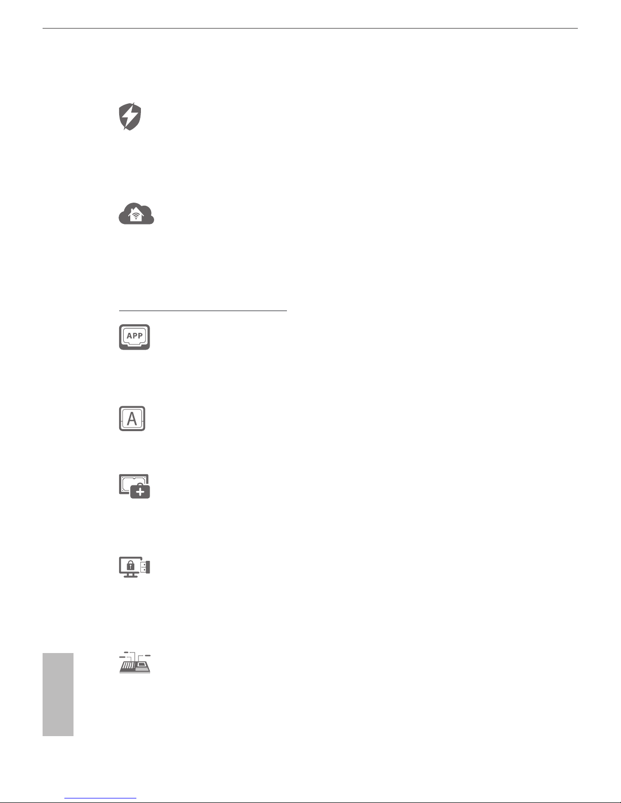
1.3 Unique Features
ASRock Full Spike Protection
A technology consists of 3 unique features: Surge Protection, Lightning Protection,
and ESD Protection. By adding specialized ICs and reworking circuits, the onboard
USB ports, LAN ports, and MOSFETs in critical areas are all well protected from
surges, spikes, and electrostatic discharge.
ASRock Cloud
ASRock partners with Kloudian to make your mobile devices connect to your PC
seamlessly! ASRock Cloud allows you to get connected with your PC’s les, music,
photos, and video clips remotely with tablets anytime, anywhere.
* OrbWeb ME is prov ided by a third part y. Restriction may apply and the oer is subject to change, termina-
tion or discontinuation by the third party without prior notice. Please visit the website for further details:
http://ww w.asrock.com/feature/cloud/index.html
ASRock APP Shop
ASRock APP Shop is designed for your convenience. We provide various apps and
support soware for users to download on the mainpage of APP Shop. You can eas-
ily optimize your system and keep your motherboard up to date with a few clicks.
ASRock A-Tuning
A-Tuning is ASRock’s multi purpose soware suite with a new interface, more new
features and improved utilities.
ASRock Disk Health Report
Displaying detailed HDD information. You can check the model names, capacities,
temperatures, SMART info, health status, and other information of your HDDs
here.
ASRock USB Key
In a world where time is money, why waste precious time everyday typing
usernames to log in to Windows? Why should we even bother memorizing those
foot long passwords? Just plug in the USB Key and let your computer log in to
windows automatically!
ASRock System Browser
ASRock System Browser shows the overview of your current PC and the devices
connected.
Page 13

H97M
7
English
ASRock APP Charger
Simply by installing the ASRock APP Charger makes your iPhone/iPad/iPod Touch
charge up to 40% faster than before on your computer. ASRock APP Charger allows
you to quickly charge many Apple devices simultaneously and even supports
continuous charging when your PC enters into Standby mode (S1), Suspend to RAM
(S3), hibernation mode (S4) or power o (S5).
ASRock XFast LAN
ASRock XFast LAN provides faster internet access, which includes the benets
listed below. LAN Application Prioritization: You can congure your application’s
priority ideally and add new programs to the list. Lower Latency in Game: Aer
setting online game’s priority higher, it can lower the latency in games. Trac
Shaping: You can watch Youtube HD videos and download simultaneously. Real-
Time Analysis of Your Data: With the status window, you can easily recognize
which data streams you are currently transferring.
ASRock XFast RAM
ASRock XFast RAM is included in F-Stream. It fully utilizes the memory space that
cannot be used under Windows® 32-bit operating systems. ASRock XFast RAM
shortens the loading time of previously visited websites, making web surng faster
than ever. And it also boosts the speed of Adobe Photoshop 5 times faster. Another
advantage of ASRock XFast RAM is that it reduces the frequency of accessing your
SSDs or HDDs in order to extend their lifespan.
ASRock Restart to UEFI
Windows® 8 brings the ultimate boot up experience. e lightning boot up speed
makes it hard to access the UEFI setup. ASRock Restart to UEFI allows users to
enter the UEFI automatically when turning on the PC. By enabling this function,
the PC will enter the UEFI directly aer you restart.
ASRock Full HD UEFI
All new Full HD UEFI with a resolution of 1920 x 1080. e UEFI should be de-
signed easy to use and setup. With Full HD resolution, now it is much easier and
clearer for all users to setup, optimize, and update their BIOS.
ASRock My Favorites in UEFI
Another handy design in ASRock UEFI. You can select and add commonly used
BIOS options to “My Favorites” by clicking the asterisk icon at the upper right hand
corner of the screen. ese chosen options will show up on “My Favorites” page in
UEFI.
Page 14

8
English
ASRock UEFI Guide
Need help to optimize your UEFI setting? Got lost among UEFI pages? Just select
“UEFI Guide”! e tutorial will explain every detailed setting and help you to cus-
tomize your UEFI easily.
ASRock Instant Flash
ASRock Instant Flash is a BIOS ash utility embedded in Flash ROM. is conve-
nient BIOS update tool allows you to update the system BIOS in a few clicks without
preparing an additional oppy diskette or other complicated ash utility. Just save
the new BIOS le to your USB storage and launch this tool by pressing <F6> or
<F2> during POST to enter the BIOS setup menu to access ASRock Instant Flash.
Please be noted that the USB ash drive or hard drive must use FAT32/16/12 le
system.
ASRock Internet Flash
ASRock Internet Flash downloads and updates the latest UEFI rmware version
from our servers for you without entering Windows® OS. Please setup network
conguration before using Internet Flash.
ASRock Crashless BIOS
ASRock Crashless BIOS allows users to update their BIOS without fear of failing. If
power loss occurs during the BIOS updating process, ASRock Crashless BIOS will
automatically nish the BIOS update procedure aer regaining power. Please note
that BIOS les need to be placed in the root directory of your USB disk. Only USB 2.0
ports support this feature.
ASRock OMG (Online Management Guard)
Administrators are able to establish an internet curfew or restrict internet access
at specied times via OMG. You may schedule the starting and ending hours of
internet access granted to other users. In order to prevent users from bypassing
OMG, guest accounts without permission to modify the system time are required.
ASRock UEFI Tech Service
Contact ASRock Tech Service by sending a support request from the UEFI setup
utility if you are having trouble with your personal computer. Users may try to
choose the category of the issue they have encountered, describe the problem in
detail, and then attach an optional picture or log le for our technical support team.
Page 15

H97M
9
English
ASRock Dehumidier Function
Users may prevent motherboard damages due to dampness by enabling
“Dehumidier Function”. When enabling Dehumidier Function, the computer
will power on automatically to dehumidify the system aer entering S4/S5 state.
ASRock Easy RAID Installer
ASRock Easy RAID Installer can help you to copy the RAID driver from the
support CD to your USB storage device. Aer copying the RAID driver to your
USB storage device, please change “SATA Mode” to “RAID”, then you can start
installing the OS in RAID mode.
ASRock Easy Driver Installer
For users that don’t have an optical disk drive to install the drivers from our support
CD, Easy Driver Installer is a handy tool in the UEFI that installs the LAN driver
to your system via an USB storage device, then downloads and installs the other
required drivers automatically.
Page 16
10
English
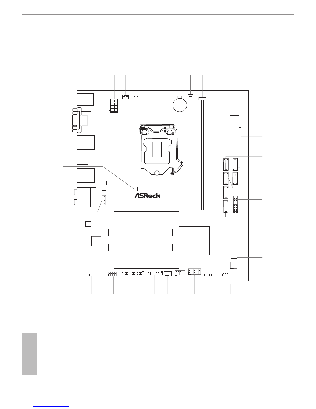
1.4 Motherboard Layout
Intel
H97
DDR 3_ A 2 (6 4 bit , 240 -pi n mod ul e)
DDR 3_ A 1 (6 4 bit , 240 -pi n mod ul e)
ATX12V 1
CMO S
Bat te ry
Sup er
I/O
USB 2.0
T: USB 0
B: U SB1
ATXPW R1
LAN
Top:
RJ- 45
USB 3. 0
T: US B0
B: USB 1
Top:
Cent ral/ Bass
Cent er:
REAR SPK
Top:
LINE IN
Cent er:
FRON T
Bott om:
Opti cal
SPDI F
Bott om:
MIC I N
CLRCM OS1
1
1
SPEAKER1
HDLED RESET
PLED PWR BTN
PANEL1
1
USB8_ 9
1
USB6 _7
1
COM1
1
1
HD_AU DIO1
H9 7 M
SATA_2 SATA_3 SATA_1 SATA_5
CHA_FA N1
CHA_FAN 2
PCI1
Ro HS
7
8
14
16
12
13
17
19
20
21
22
18
15
24
2
CPU_FAN 1
CPU_FAN 2
3
4
6
5
1
64Mb
BIOS
23
HDM I1
VGA1
DVI 1
PCI2
USB 3.0
T: USB 4
B: U SB5
Audio
CODEC
1
SPDIF1_ OUT1
PCIE 1
X
Fas t R AM
X
Fas t L AN
Fro nt USB 3.0
PCIE 2
PWR_FAN 1
1
TPMS1
1
1
LPT1
CI1
USB 2. 0
T: US B2
B: USB 3
1
USB3_ 2_3
9
10
11
SATA_0 SATA_4
25
26
PS2
Keyb oar d/
Mous e
Page 17

H97M
11
English
No. Description
1 ATX 12V Power Connector (ATX12V1)
2 CPU Fan Connector (CPU_FAN1)
3 CPU Fan Connector (CPU_FAN2)
4 Power Fan Connector (PWR_FAN1)
5 2 x 240-pin DDR3 DIMM Slots (DDR3_A1, DDR3_A2)
6 ATX Power Connector (ATXPWR1)
7 SATA3 Connector (SATA_5)
8 SATA3 Connector (SATA_4)
9 SATA3 Connector (SATA_0)
10 SATA3 Connector (SATA_1)
11 SATA3 Connector (SATA_3)
12 USB 3.0 Header (USB3_2_3)
13 SATA3 Connector (SATA_2)
14 Clear CMOS Jumper (CLRCMOS1)
15 System Panel Header (PANEL1)
16 Chassis Speaker Header (SPEAKER1)
17 USB 2.0 Header (USB6_7)
18 USB 2.0 Header (USB8_9)
19 Chassis Fan Connector (CHA_FAN1)
20 TPM Header (TPMS1)
21 Print Port Header (LPT1)
22 COM Port Header (COM1)
23 Chassis Intrusion Header (CI1)
24 Front Panel Audio Header (HD_AUDIO1)
25 SPDIF Out Connector (SPDIF_OUT)
26 Chassis Fan Connector (CHA_FAN2)
Page 18
12
English
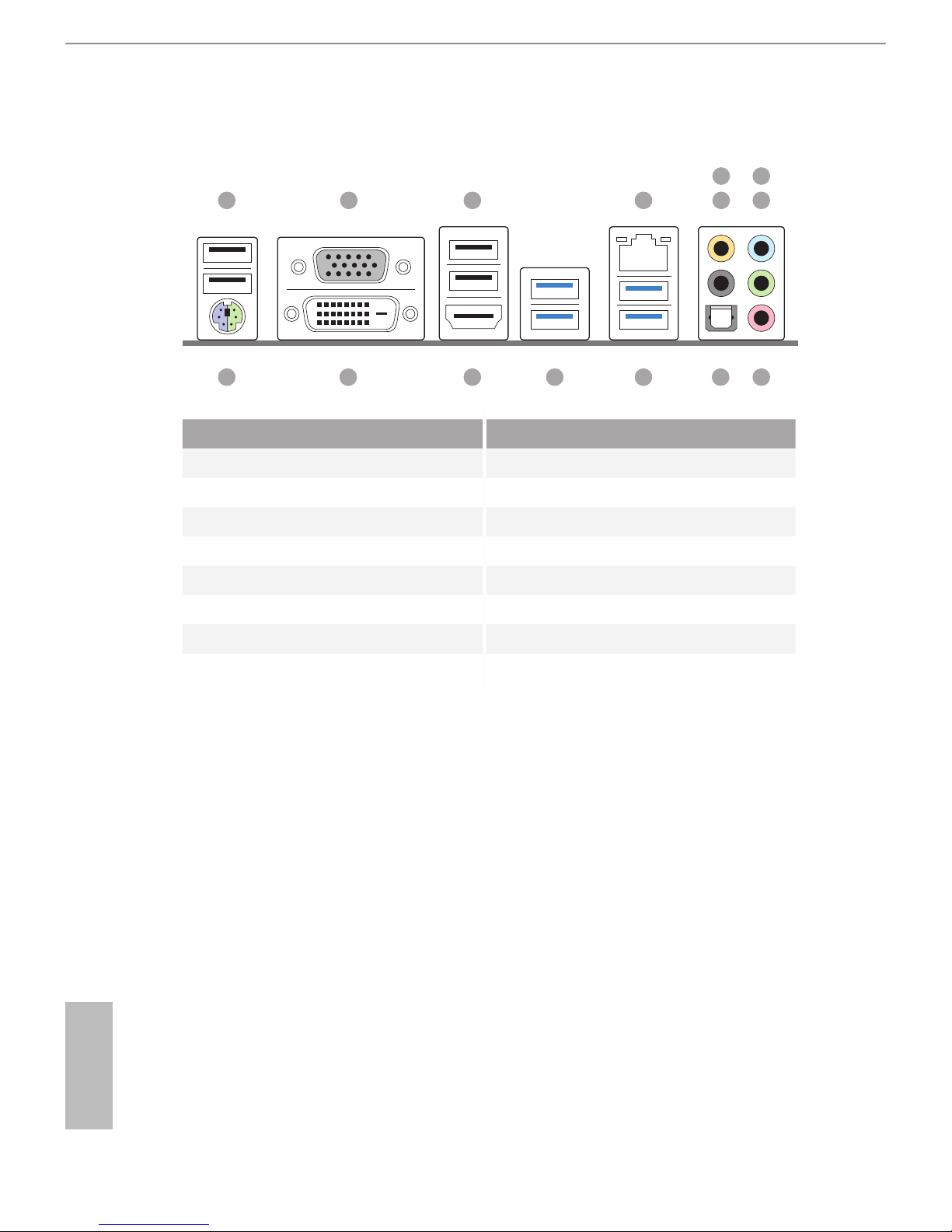
1.5 I/O Panel
No. Description No. Description
1 USB 2.0 Ports (USB01) 9 Microphone (Pink)
2 D-Sub Port 10 Optical SPDIF Out Port
3 USB 2.0 Ports (USB23) 11 USB 3.0 Ports (USB3_01)
4 LAN RJ-45 Port* 12 USB 3.0 Ports (USB45)
5 Central / Bass (Orange) 13 HDMI Port
6 Rear Speaker (Black) 14 DVI-D Port
7 Line In (Light Blue) 15 PS/2 Mouse/Keyboard Port
8 Front Speaker (Lime)**
91015 11121314
1 2 3 4 6
5
8
7
Page 19
H97M
13
English
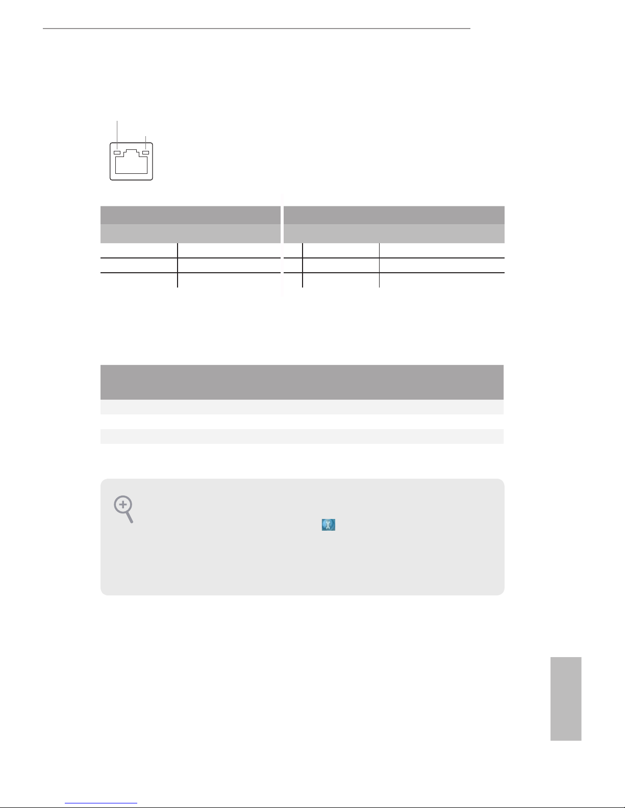
* ere are two LEDs on each LAN port. Please refer to the table below for the LAN port LED indications.
Activity / Link LED Speed LED
Status Description Status Description
O No Link O 10Mbps connection
Blinking Data Activity Orange 100Mbps connection
On Link Green 1Gbps connection
** If you use a 2-channel speaker, please connect the speaker’s plug into “Front Speaker Jack”. See the table below
for connection details in accordance with the type of speaker you use.
Audio Output
Channels
Front Speaker
(No. 8)
Rear Speaker
(No. 6)
Central / Bass
(No. 5)
Line In
(No. 7)
2 V -- -- --
4 V V -- --
6 V V V --
8 V V V V
ACT/LINK LED
SPEED LED
LAN Por t
To enable Multi-Streaming, you need to connect a front panel audio cable to the front
panel audio header. Aer restarting your computer, you will nd the “Mixer” tool
on your system. Please select “Mixer ToolBox” , click “Enable playback multistreaming”, and click “ok”. Choose “2CH”, “4CH”, “6CH”, or “8CH” and then you are
allowed to select “Realtek HDA Primary output” to use the Rear Speaker, Central/
Bass, and Front Speaker, or select “Realtek HDA Audio 2nd output” to use the front
panel audio.
Page 20

14
English
is is a Micro ATX form factor motherboard. Before you install the motherboard,
study the conguration of your chassis to ensure that the motherboard ts into it.
Pre-installation Precautions
Take note of the following precautions before you install motherboard components
or change any motherboard settings.
•
Make sure to unplug the power cord before installing or removing the motherboard
components. Failure to do so may cause physical injuries and damages to motherboard
components.
•
In order to avoid damage from static electricity to the motherboard’s components,
NEVER place your motherboard directly on a carpet. Also remember to use a grounded
wrist strap or touch a safety grounded object before you handle the components.
•
Hold components by the edges and do not touch the ICs.
•
Whenever you uninstall any components, place them on a grounded anti-static pad or
in the bag that comes with the components.
•
When placing screws to secure the motherboard to the chassis, please do not over-
tighten the screws! Doing so may damage the motherboard.
Chapter 2 Installation
Page 21

H97M
15
English
2.1 Installing the CPU
1. Before you insert the 1150-Pin CPU into the socket, please check if the PnP cap is on
the socket, if the CPU surface is unclean, or if there are any bent pins in the socket.
Do not force to insert the CPU into the socket if above situation is found. Otherwise,
the CPU will be seriously damaged.
2. Unplug all power cables before installing the CPU.
2
1
A
B
Page 22

16
English
4
5
3
Page 23

H97M
17
English
Please save and replace the cover if the processor is removed. e cover must be placed
if you wish to return the motherboard for aer service.
Page 24

18
English
2.2 Installing the CPU Fan and Heatsink
1 2
C
P
U
_
FA
N
Page 25

H97M
19
English
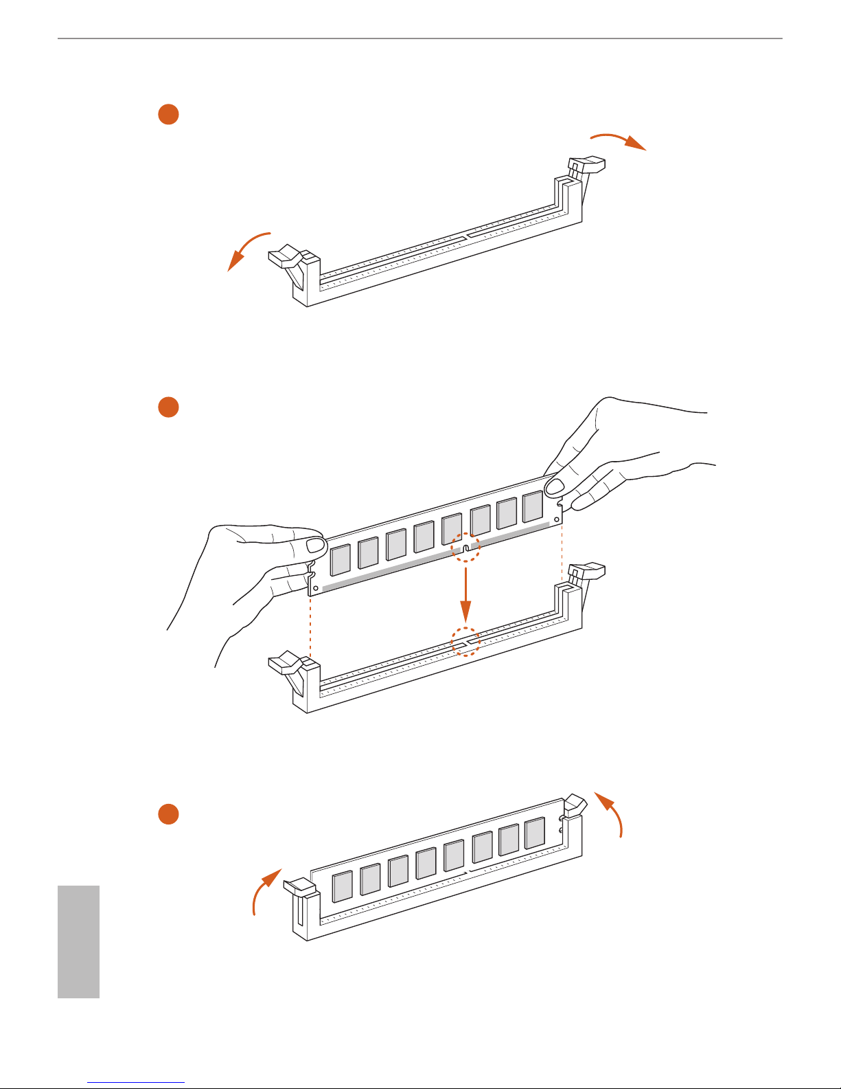
2.3 Installing Memory Modules (DIMM)
is motherboard provides two 240-pin DDR3 (Double Data Rate 3) DIMM slots,
and supports Dual Channel Memory Technology.
e DIMM only ts in one correct orientation. It will cause permanent damage to
the motherboard and the DIMM if you force the DIMM into the slot at incorrect
orientation.
1. For dual channel conguration, you always need to install identical (the same
brand, speed, size and chip-type) DDR3 DIMM pairs.
2. It is unable to activate Dual Channel Memory Technology with only one memory
module installed.
3. It is not allowed to install a DDR or DDR2 memory module into a DDR3 slot;
otherwise, this motherboard and DIMM may be damaged.
Page 26
20
English
1
2
3
Page 27

H97M
21
English
2.4 Expansion Slots (PCI and PCI Express Slots)
ere are 2 PCI slots and 2 PCI Express slots on the motherboard.
PCI slot:
e PCI1 and PCI2 slots are used to install expansion cards that have 32-bit PCI
interface.
PCIe slots:
PCIE1 (PCIe 3.0 x16 slot) is used for PCI Express x16 lane width graphics cards.
PCIE2 (PCIe 2.0 x16 slot) is used for PCI Express x4 lane width graphics cards.
PCIe Slot Congurations
PCIE1 PCIE2
Single Graphics Card x16 N/A
Two Graphics Cards in
CrossFireXTM Mode
x16 x4
For a better thermal environment, please connect a chassis fan to the motherboard’s
chassis fan connector (CHA_FAN1 or CHA_FAN2) when using multiple graphics
cards.
Before installing an expansion card, please make sure that the power supply is
switched o or the power cord is unplug ged. Please read the documentation of the
expansion card and make necessary hardware settings for the card before you start
the installation.
Page 28
22
English
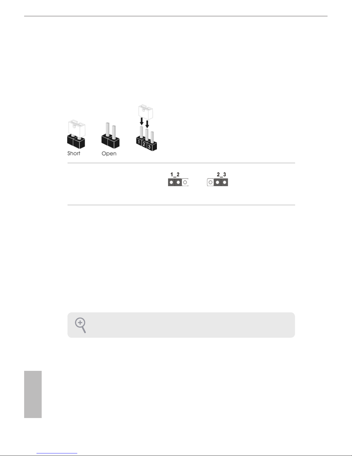
2.5 Jumpers Setup
e illustration shows how jumpers are setup. When the jumper cap is placed on
the pins, the jumper is “Short”. If no jumper cap is placed on the pins, the jumper
is “Open”. e illustration shows a 3-pin jumper whose pin1 and pin2 are “Short”
when a jumper cap is placed on these 2 pins.
Clear CMOS Jumper
(CLRCMOS1)
(see p.10, No. 14)
CLRCMOS1 allows you to clear the data in CMOS. To clear and reset the system
parameters to default setup, please turn o the computer and unplug the power
cord from the power supply. Aer waiting for 15 seconds, use a jumper cap to
short pin2 and pin3 on CLRCMOS1 for 5 seconds. However, please do not clear
the CMOS right aer you update the BIOS. If you need to clear the CMOS when
you just nish updating the BIOS, you must boot up the system rst, and then shut
it down before you do the clear-CMOS action. Please be noted that the password,
date, time, and user default prole will be cleared only if the CMOS battery is
removed.
Clear CMOSDefault
If you clear the CMOS, the case open may be detected. Please adjust the BIOS option
“Clear Status” to clear the record of previous chassis intrusion status.
Page 29

H97M
23
English
2.6 Onboard Headers and Connectors
System Panel Header
(9-pin PANEL1)
(see p.10, No. 15)
Connect the power
switch, reset switch and
system status indicator on
the chassis to this header
according to the pin
assignments below. Note
the positive and negative
pins before connecting
the cables.
GND
RE S ET #
PW R BT N#
PL E D-
PL E D+
GND
HD L ED -
HD L ED +
1
GND
PWRBTN (Power Switch):
Connect to the power switch on the chassis front panel. You may congure the way to
turn o your system using the power switch.
RESET (Reset Switch):
Connect to the reset switch on the chassis front panel. Press the reset switch to restart
the computer if the computer freezes and fails to perform a normal restart.
PLED (System Power LED):
Connect to the power status indicator on the chassis front panel. e LED is on when
the system is operating. e LED keeps blinking when the system is in S1/S3 sleep state.
e LED is o when the system is in S4 sleep state or powered o (S5).
HDLED (Hard Drive Activity LED):
Connect to the hard drive activity LED on the chassis front panel. e LED is on when
the hard drive is reading or writing data.
e front panel design may dier by chassis. A front panel module mainly consists
of power switch, reset switch, power LED, hard drive activity LED, speaker and etc.
When connecting your chassis front panel module to this header, make sure the wire
assignments and the pin assignments are matched correctly.
Onboard headers and connectors are NOT jumpers. Do NOT place jumper caps over
these headers and connectors. Placing jumper caps over the headers and connectors
will cause permanent damage to the motherboard.
Page 30

24
English
Serial ATA3 Connectors
(SATA_0:
see p.10, No. 9)
(SATA_1:
see p.10, No. 10)
(SATA_2:
see p.10, No. 13)
(SATA_3:
see p.10, No. 11)
(SATA_4:
see p.10, No. 8)
(SATA_5:
see p.10, No. 7)
ese six SATA3
connectors support SATA
data cables for internal
storage devices with up to
6.0 Gb/s data transfer rate.
USB 2.0 Headers
(9-pin USB6_7)
(see p.10, No. 17)
(9-pin USB8_9)
(see p.10, No. 18)
Besides four USB 2.0 ports
on the I/O panel, there
are two headers on this
motherboard. Each USB
2.0 header can support
two ports.
USB 3.0 Header
(19-pin USB3_2_3)
(see p.10, No. 12)
Besides four USB 3.0
ports on the I/O panel,
there is one header on this
motherboard. Each USB
3.0 header can support
two ports.
Front Panel Audio Header
(9-pin HD_AUDIO1)
(see p.10, No. 24)
is header is for
connecting audio devices
to the front audio panel.
DUM MY
GND
GND
P+
P-
USB _P WR
P+
P-
USB _P WR
1
1
Int A_P B_D +
Dum my
Int A_P B_D -
GND
Int A_P B_S ST X+
GND
Int A_P B_S ST X-
Int A_P B_S SR X+
Int A_P B_S SR X-
Vbu sVbu s
Vbu s
Int A_PA _SS RX-
Int A_PA _SS RX+
GND
Int A_PA _SS TX-
Int A_PA _SS TX+
GND
Int A_PA _D-
Int A_PA _D+
J_ S EN SE
OU T 2_ L
1
MI C _R ET
PR E SE NC E#
GND
OU T 2_ R
MI C 2_ R
MI C 2_ L
OUT_RET
SATA_1SATA_2 SATA_3
SATA_5
SATA_0
SATA_4
Page 31

H97M
25
English
Chassis Speaker Header
(4-pin SPEAKER1)
(see p.10, No. 16)
Please connect the chassis
speaker to this header.
SPDIF Out Connector
(2-pin SPDIF_OUT1)
(see p.10, No. 25)
Please connect the
SPDIF_OUT connector of
a HDMI VGA card to this
header with a cable.
Chassis and Power Fan
Connectors
(4-pin CHA_FAN1)
(see p.10, No. 19)
(3-pin CHA_FAN2)
(see p.10, No. 26)
(3-pin PWR_FAN1)
(see p.10, No. 4)
Please connect fan cables
to the fan connectors and
match the black wire to
the ground pin.
1. High Denition Audio supports Jack Sensing, but the panel wire on the chassis must
support HDA to function correctly. Please follow the instructions in our manual and
chassis manual to install your system.
2. If you use an AC’97 audio panel, please install it to the front panel audio header by
the steps below:
A. Connect Mic_ IN (MIC) to MIC2_L.
B. Connect Audio_ R (RIN) to OUT2_R and Audio_L (LIN) to OUT2_L.
C. Connect Ground (GND) to Ground (GND).
D. MIC_ RET and OUT_RET are for the HD audio panel only. You don’t need to
connect them for the AC’97 audio panel.
E. To activate the front mic, go to the “FrontMic” Tab in the Realtek Control panel
and adjust “Recording Volume”.
1
+5V
DUMM Y
DUMM Y
SPEA KE R
SPD IF OU T
GND
1
GND
+12V
FAN_SPE ED
FAN_ SP E ED
FAN_ SP E ED _CO NT ROL
GND
+12 V
1 2 3 4
Page 32

26
English
CPU Fan Connectors
(4-pin CPU_FAN1)
(see p.10, No. 2)
(3-pin CPU_FAN2)
(see p.10, No. 3)
is motherboard pro-
vides a 4-Pin CPU fan
(Quiet Fan) connector.
If you plan to connect a
3-Pin CPU fan, please
connect it to Pin 1-3.
ATX Power Connector
(24-pin ATXPWR1)
(see p.10, No. 6)
is motherboard pro-
vides a 24-pin ATX power
connector. To use a 20-pin
ATX power supply, please
plug it along Pin 1 and Pin
13.
ATX 12V Power
Connector
(8-pin ATX12V1)
(see p.10, No. 1)
is motherboard pro-
vides an 8-pin ATX 12V
power connector. To use a
4-pin ATX power supply,
please plug it along Pin 1
and Pin 5.
Serial Port Header
(9-pin COM1)
(see p.10, No. 22)
is COM1 header
supports a serial port
module.
12
1
24
13
5
8
1
4
GND
+12V
CPU_FAN _S PE ED
FAN _S PE ED _C ON TR OL
GND
FAN_ VO LTAGE
FAN_ SP EE D
Page 33

H97M
27
English
Chassis Intrusion Header
(2-pin CI1)
(see p.10, No. 23)
is motherboard
supports CASE OPEN
detection feature that
detects if the chassis cove
has been removed. is
feature requires a chassis
with chassis intrusion
detection design.
TPM Header
(17-pin TPMS1)
(see p.10, No. 20)
is connector supports
Trusted Platform Module
(TPM) system, which can
securely store keys, digital
certicates, passwords,
and data. A TPM system
also helps enhance
network security, protects
digital identities, and
ensures platform integrity.
Print Port Header
(25-pin LPT1)
(see p.10, No. 21)
is is an interface
for print port cable
that allows convenient
connection of printer
devices.
1
AFD #
ERR OR #
PIN IT #
GND
SLI N#
STB #
SPD 0
SPD 1
SPD 2
SPD 3
SPD 4
SPD 5
SPD 6
SPD 7
ACK #
BUS Y
PE
SLC T
1
1
Signal
GND
Page 34

28
English
2.7 CrossFireXTM and Quad CrossFireXTM Operation Guide
is motherboard supports CrossFireXTM and Quad CrossFireXTM that allows you to
install up to two identical PCI Express x16 graphics cards. Currently CrossFireXTM
and Quad CrossFireXTM are supported with Windows® 7 / 7 64-bit / 8 / 8 64-bit / 8.1
/ 8.1 64-bit OS.
2.7.1 Installing Two CrossFireXTM-Ready Graphics Cards
Step 1
Insert one graphics card into PCIE1 slot
and the other graphics card to PCIE2 slot.
Make sure that the cards are properly
seated on the slots.
Step 2
Connect two graphics cards by installing
a CrossFire Bridge on the CrossFire Bridge
Interconnects on the top of the graphics
cards. (e CrossFire Bridge is provided
with the graphics card you purchase, not
bundled with this motherboard. Please
refer to your graphics card vendor for
details.)
1. You should only use identical CrossFireXTM-ready graphics cards that are AMD
certied.
2. Make sure that your graphics card driver supports AMD CrossFireXTM technology.
Download the drivers from the AMD’s website: www.amd.com
3. Make sure that your power supply unit (PSU) can provide at least the minimum
power your system requires. It is recommended to use a AMD certied PSU. Please
refer to the AMD’s website for details.
4. If you pair a 12-pipe CrossFireXTM Edition card with a 16-pipe card, both cards will
operate as 12-pipe cards while in CrossFireXTM mode.
5. Dierent CrossFireXTM cards may require dierent methods to enable CrossFireXTM. Please refer to AMD graphics card manuals for detailed installation guide.
CrossFire Bridge
Page 35

H97M
29
English
Step 3
Connect a VGA cable or a DVI cable to the
monitor connector or the DVI connec-
tor of the graphics card that is inserted to
PCIE1 slot.
Page 36

30
English
Step 1
Power on your computer and boot into OS.
Step 2
Remove the AMD drivers if you have any VGA drivers installed in your system.
Step 3
Install the required drivers and CATALYST Control Center then restart your
computer. Please check AMD’s website for details.
2.7.2 Driver Installation and Setup
Step 4
Double-click the AMD Catalyst Control
Center icon in the Windows® system tray.
Step 5
In the le pane, click Performance and
then AMD CrossFireXTM. en select
Enable AMD CrossFireX and click Apply.
Select the GPU number according to your
graphics card and click Apply.
AMD Catalyst Control Center
e Catalyst Uninstaller is an optional download. We recommend using this utility to
uninstall any previously installed Catalyst drivers prior to installation. Please check
AMD’s website for AMD driver updates.
Page 37

H97M
31
English
Chapter 3 Software and Utilities Operation
3.1 Installing Drivers
e Support CD that comes with the motherboard contains necessary drivers and
useful utilities that enhance the motherboard’s features.
Running The Support CD
To begin using the support CD, insert the CD into your CD-ROM drive. e CD
automatically displays the Main Menu if “AUTORUN” is enabled in your computer.
If the Main Menu does not appear automatically, locate and double click on the le
“ASRSETUP.EXE” in the Support CD to display the menu.
Drivers Menu
e drivers compatible to your system will be auto-detected and listed on the
support CD driver page. Please click Install All or follow the order from top to
bottom to install those required drivers. erefore, the drivers you install can work
properly.
Utilities Menu
e Utilities Menu shows the application soware that the motherboard supports.
Click on a specic item then follow the installation wizard to install it.
To improve Windows 7 compatibility, please download and install the following hot
x provided by Microso.
“KB2720599”: http://support.microso.com/kb/2720599/en-us
Page 38

32
English
3.2 A-Tuning
A-Tuning is ASRock’s multi purpose soware suite with a new interface, more new
features and improved utilities, including XFast RAM, Dehumidier, Good Night
LED, FAN-Tastic Tuning, OC Tweaker and a whole lot more.
3.2.1 Installing A-Tuning
When you install the all-in-one driver to your system from ASRock’s support CD,
A-Tuning will be auto-installed as well. Aer the installation, you will nd the icon
“A-Tuning“ on your desktop. Double-click the “A-Tuning“ icon, A-Tuning
main menu will pop up.
3.2.2 Using A-Tuning
ere are six sections in A-Tuning main menu: Operation Mode, Tools, OC
Tweaker, System Info, Live Update, Tech Service and Settings.
Operation Mode
Choose an operation mode for your computer.
Page 39

H97M
33
English
Tools
Various tools and utilities.
XFast RAM
Boost the system’s performance and extend the HDD’s or SDD’s lifespan! Create a
hidden partition, then assign which les should be stored in the RAM drive.
XFast LAN
Boost the speed of your internet connection! Select a specic mode for making the
designated program's priority highest.
Fast Boot
Fast Boot minimizes your computer's boot time. Please note that Ultra Fast mode
is only supported by Windows 8.1/8 and the VBIOS must support UEFI GOP if you
are using an external graphics card.
OMG
Schedule the starting and ending hours of Internet access granted to other users.
Place X marks on the time table to disable the Internet.
Good Night LED
Switch o the Power/HDD LEDs when the system is on, and automatically switch
o the Power and Keyboard LEDs when the system enters into Standby/Hibernation
mode.
Page 40

34
English
FAN-Tastic Tuning
Congure up to ve dierent fan speeds using the graph. e fans will automatically
shi to the next speed level when the assigned temperature is met.
Dehumidier
Prevent motherboard damages due to dampness. Enable this function and
congure the period of time until the computer powers on, and the duration of the
dehumidifying process.
USB Key
Plug in the USB Key and let your computer log in to windows automatically!
OC DNA
OC DNA is an unique soware which helps to save your OC settings as a prole.
en you can send this OC setting prole to the friends.
Disk Health Report
Disk Health Report is a hard disk health monitoring utility that displays detailed
HDD information, such as hard disk model, serial number, rmware, power on
count, power on hours, S.M.A.R.T. values, current temperature, etc. HDD, SSD
and optical disk drives are all supported. e health status block displays Good
(in green color), Caution (in yellow color) or Bad (in red color). Click on the health
status icon to congure settings for an alert to be triggered.
Page 41

H97M
35
English
OC Tweaker
Congurations for overclocking the system.
System Info
View information about the system.
*e System Browser tab may not appear for certain models.
Page 42

36
English
Live Update
Check for newer versions of BIOS or drivers.
Tech Service
Contact Tech Service if you have problems with your computer. Please leave your
contact information along with details of the problem.
Page 43

H97M
37
English
Settings
Congure ASRock A-Tuning. Click to select "Auto run at Windows Startup" if you
want A-Tuning to be launched when you start up the Windows operating system.
Page 44

38
English
3.3 Intel® Rapid Start Technology
Intel® Rapid Start Technology enables your system to wake up faster from deep
sleep, saving time and power consumption. Feel secure to know that your system
will resume to working condition even if an unexpected power loss happens while
the PC is in sleep mode.
3.3.1 System Requirements
• Conrm whether your motherboard supports this feature.
• Operating system: Microso Windows 8.1/8/7 (32- or 64-bit edition)
• Set the SATA mode to AHCI. If Windows 8.1/8/7 is already installed under
IDE mode, directly changing the SATA mode to AHCI may cause Windows
8/7 to crash while booting. If your system is not in AHCI mode, please follow
the instructions below.
1. Press Win + R simultaneously in Windows 8/7, type "Regedit" into the word
box then click OK.
2. Enter into HKEY_LOCAL_MACHINE\SYSTEM\CurrentControlSet\services\
msahci in Windows Registry Editor. Double click on the value Start and
change the value from 3 into 0. Click on OK.
ere are certain risks. Please backup any important data before operating to avoid
loss.
Page 45

H97M
39
English
3. Exit the Registry Editor window and restart the computer.
4. Press F2 to enter BIOS, then go to Advanced ‐> Storage Conguration and
change SATA Mode to AHCI. Press F10 to save changes and exit.
5. Enter Windows 8/7. Windows will discover the new device and install AHCI
drivers automatically.
3.3.2 Setup Guide
Conguring Rapid Start
Step 1
Run ASRock Rapid Start utility from Start -> All Programs -> ASRock Utility.
Step 2
If you have more than one hard drives in your system, you must select one, then
choose the Partition Size desired for your hidden partition and click on Create. e
system will automatically create a hidden partition according to your settings. If
there are SSD’s installed into your system, it is recommended to create the partition
on the SSD.
Page 46

40
English
Step 3
When prompted to restart aer the setup, click Yes to reboot.
Step 4
Double-click the Intel® Rapid Start Technology Manager icon in the Windows
system tray.
Page 47

H97M
41
English
Step 5
Make sure Rapid Start is on. Drag the slider to congure the time. For example, if
the timer value is set to ten minutes, the system will enable Rapid Start mode aer
entering sleep state for ten minutes. If the timer is set to 0 minutes, Windows will
immediately enable Rapid Start mode as it enters sleep state.
Using Rapid Start
1. You may shut down the computer without terminating the applications or les
you are executing currently. Click on Windows Start ‐> the arrow next to Shut
down, and click on Sleep.
2. Windows system will enter sleep state.
3. According to your settings in Rapid Start Technology Manager, the system
will automatically wake up and enable Rapid Start mode aer entering sleep
Page 48

42
English
state for a period of time. e power of the computer in Rapid Start mode can
be cut o, it will not cause data loss of the programs or les you were executing
before entering sleep state.
4. When you wish to continue to use the computer just hit the power button, the
system will rapidly return to Windows, the programs and les which you were
using before entering sleep state will be accessible immediately.
Page 49

H97M
43
English
3.4 Intel® Smart Connect Technology
Intel® Smart Connect Technology is a feature that periodically wakes your computer
from Windows® sleep state to refresh email or social networking applications. It
saves your waiting time and keeps the content always up-to-date.
3.4.1 System Requirements
• Conrm whether your motherboard supports this feature.
• Operating system: Microso Windows 8.1/8/7 (32- or 64-bit edition)
• Set the SATA mode to AHCI. If Windows 8.1/8/7 is already installed under
IDE mode, directly changing the SATA mode to AHCI may cause Windows
8/7 to crash while booting. If your system is not in AHCI mode, please follow
the instructions below.
1. Press Win + R simultaneously in Windows 8/7, type "Regedit" into the word
box then click OK.
2. Enter into HKEY_LOCAL_MACHINE\SYSTEM\CurrentControlSet\services\
msahci in Windows Registry Editor. Double click on the value Start and
change the value from 3 into 0. Click on OK.
ere are certain risks. Please backup any important data before operating to avoid
loss.
Page 50

44
English
3.4.2 Setup Guide
Installing ASRock Smart Connect Utility
Step 1
Install ASRock Smart Connect Utility, which is located in the folder at the following
path of the Support CD: \ ASRock Utility > Smart Connect.
Step 2
Once installed, run ASRock Smart Connect from your desktop or go to Windows
Start -> All Programs -> ASRock Utility.
Page 51

H97M
45
English
Step 3
Click the Add button. Take Foxmail as an example, add Foxmail to the Application
list.
Step 4
Select Foxmail from the Application List, then click the arrow pointing right to add
this application to the Smart Connect List.
Step 5
Click Apply to enable Smart Connect.
Page 52

46
English
Step 6
Double-click the Intel® Smart Connect Technology Manager icon in the
Windows system tray.
Step 7
Drag the slider to congure how oen the system will connect to the network to
download updates. Shorter durations will provide more frequent updates, but may
cause more power consumption.
Using Smart Connect
1. Keep the applications which you wish to connect to the internet and receive
updates while the system is in sleep state running. Foxmail for instance, keep
Foxmail running.
2. Click on Windows Start -> the arrow next to Shut down, and click on Sleep.
3. Windows system will enter sleep state.
Page 53

H97M
47
English
4. e system will wake up from sleep state periodically, and then start to update
Foxmail. e screen will not display anything so the computer can maintain
minimum power usage. Aerwards, the system will automatically return to
sleep state again.
5. Upon waking up the system, you will nd the new mail that were sent to you
during sleep state are already updated and ready to be read in Foxmail.
Page 54

48
English
3.5 ASRock Cloud
ASRock partners with Kloudian to make your mobile devices connect to
your PC seamlessly!
Have you ever been in a situation where you emergently needed certain files in your
computer, however the computer was ga z il lion mi l e s aw ay out of reach? ASRock
Cloud includes severa l technologies and software solutions for remotely controlling
your computer, even if the computer is in off mode. For ASRock motherboards with a
Qualcomm® Atheros® LAN chip, ASRock Cloud allows users to remotely wake up their
computers via the internet by using a secondary device, such as a smartphone or tablet.
Users may use Kloudian® Orbweb.ME Professional to remotely wake up and control
their computers, or they could wake up the computer then use any other preferred remote
desktop application. is motherboard supports Security Wake On Internet Technology
with the onboard Qualcomm® Atheros® LAN, so you can connect with your PC from
anywhere in the world. You will be able to power your PC on or turn it o, monitor and
take control of it remotely with another smartphone, tablet or computer.
Page 55

H97M
49
English
3.5.1 Qualcomm® Atheros® Security Wake On Internet
Technology
Qualcomm® Atheros® Security Wake On Internet Technology allows you to wake up and
remote control your home computer from sleep or shutdown state.
Before conguring this feature, verify the followings on your host computer:
• Make sure that the "PCIE Devices Power On" is enabled in UEFI SETUP
UTILITY > Advanced > ACPI Conguration.
• Make sure that the "Shutdown Wake Up" and "SWOI" are enabled in Device
Manager > Network Adapters > Qualcomm Atheros AR8171/8175 PCI-E Gigabit
Ethernet Controller > Advanced.
*"SWOI" may not appear in certain driver versions.
*e UEFI screen is for reference only. e actual screen may dier by model.
Page 56

50
English
3.5.2 Conguring and Using Orbweb.ME Professional
Kloudian® Orbweb.ME Professional is a remote control software allowing you to easily
access and control t he remote host installed with the Orbweb.ME Professional host
soware.
Installing Orbweb.ME Professional on the Host Computer
You ca n f ind the Orbweb.ME Professiona l host soft wa re in the Support CD or just
download it from http://orbweb.me.
Step 1
Click on the Orbweb.ME Professional installer package le to start installation.
Step 2
Follow the onscreen instructions to complete the installation.
Step 3
When installation completes, reboot the computer.
Signing Up for Host Computer Registration
Step 1
Double-click the Orbweb.ME Professional icon on your desktop.
Step 2
On the Orbweb.ME Portal login page, click Sign Up to create an Orbweb.ME account and
name your host computer.
Page 57

H97M
51
English
Step 3
You will receive a verication email. Follow the steps in the email to verify your account.
Aer verifying your account, you can access your PC through web browsers at
http://orbweb.me.
On the Account Veried page, if you click Go to My Computers, you will see the Orbweb.
ME portal page as a client.
Setting Up Shared Folders on Host Computer
Step 1
Double-click the Orbweb.ME Professional icon on your desktop.
Or, if you just nished signing up for your host computer, you can click Congure this
computer in the screen to begin.
Step 2
Click Folder Settings tab and the default shared folders display.
To add a folder, click . Select a folder to add it into Orbweb.ME. en click Save.
You can access the documents in these shared folders on the host computer remotely
through Xplorer from your client device.
Page 58

52
English
REMOTE ACCESS FROM A CLIENT DEVICE
Using Remote Wake-Up
Remote Wake-Up allows you to remotely put your host computer to sleep and wake your
host computer up from a client device.
If you use a motherboard with dual LAN ports, please disable one of the LAN ports
to use the Remote Wake-Up function. To do so, go to Control Panel > Network and
Sharing Center > Manage Network Connections, right-click Local Area Connections
and select Disable.
For Windows PC users:
Step 1
Go to Orbweb.ME portal login page: http://orbweb.me
Step 2
Log in with your Orbweb.ME account and password.
Step 3
Find the host computer from the list by the computer name you give.
Online / Green Ready to Connect / Blue Online / Blue
Oine / Gray Unable to Connect / Gray Wakable / Red
Wakeable mode
e lastest version of Java is required to be installed to use the Remote Desktop and
Xplorer functions.
Page 59

H97M
53
English
Step 4
Click and power options appear. Click to select Restart, Sleep or Shut Down.
Select Restart from the options to restart your host computer remotely.
When you select Sle ep or Shut Down, if the host device is WOW(Wa ke-On-Wan)
compatible, you can put your host computer to sleep (S3/S4) or shut down your host
computer (S5) remotely. e host status in the Status column shows oine and ready to be
awaked and the power option shows wakable .
To wake up the computer, click .
For iOS or Android Mobile Devices users:
Download and install “Orbweb.ME Professional” app from the App Store (iOS) or Play
Store (Android).
Step 1
Tap the “Orbweb.ME Professional” app icon to launch it.
Step 2
Log in with your Orbweb.ME account and password.
Step 3
Tap the Power Options icon and power options appear.
Tap to select Restart, Sleep or Shutdown.
Please be noted that if the host device is not WOW compatible, the host status icon
will turn oine and the power option icon will disappear. You have to physically
wake up computer in order to bring power option icon back to online.
Page 60

54
English
Using Remote Desktop
Remote Desktop allows you to remotely access your host computer from a client device.
For Windows PC users:
Step 1
Go to Orbweb.ME portal login page: http://orbweb.me
Step 2
Log in with your Orbweb.ME account and password.
Step 3
Click the Connect icon .
Step 4
Click on Remote Desktop.
If the Remote Desktop Connection dialog appears, click Connect to continue.
Step 5
Enter the Windows password to log in and you will see the desktop of your host computer.
Please be noted that if the host device is not WOW compatible, the host status icon
will turn oine and the power option icon will dissappear. You have to physically
wake up computer in order to bring power option icon back to online.
Please refer to the user manual of the Kloudian® Orbweb.ME Professional for more
instructions on how to use Orbweb.ME Professional.
Page 61

H97M
55
English
For iOS or Android Mobile Devices users:
Download and install “Orbweb.ME Professional” app from the App Store (iOS) or Play
Store (Android).
Step 1
Tap the “Orbweb.ME Professional” app icon to launch it.
Step 2
Log in with your Orbweb.ME account and password.
Step 3
Tap the host computer name that you want to access under the Remote Desktop section.
Step 4
Enter the Windows password to log in and you will see the desktop of your host computer.
Page 62

56
English
Using Xplorer
Xplorer allows you to remotely access documents on your host computer from a client
device.
For Windows PC users:
Step 1
Go to Orbweb.ME portal login page: http://orbweb.me
Step 2
Log in with your Orbweb.ME account and password.
Step 3
Click the Connect icon .
Step 4
Click on Xplorer.
Step 5
Root directory displays. Click on a folder name to open the folder.
Step 6
Click on a le name to preivew the le.
You can also delete, rename, move, and copy a selected le. For more instructions on how
to use Xplorer, refer to the user manual of the Kloudian® Orbweb.ME Professional.
Page 63

H97M
57
English
Tutorial Video
For iOS or Android Mobile Devices users:
Download and install “Orbweb.ME Professional” app from the App Store (iOS) or Play
Store (Android).
Step 1
Tap the “Orbweb.ME Professional” app icon to launch it.
Step 2
Log in with your Orbweb.ME account and password.
Step 3
Tap the Connect icon .
Step 4
Tap a folder name under the Xplorer section and you can see the les in this folder.
Tap a le name to preivew the le.
You can also delete, rename, move, and copy a selected le. For more instructions
on how to use Xplorer, refer to the user manual of the Kloudian® Orbweb.ME
Professional.
Page 64

58
English
3.6 ASRock APP Shop
e ASRock APP Shop is an online store for purchasing and downloading soware
applications for your ASRock computer. You can install various apps and support
utilities quickly and easily, and optimize your system and keep your motherboard
up to date simply with a few clicks.
Double-click on your desktop to access ASRock APP Shop utility.
*You need to be connected to the Internet to download apps from the ASRock APP Shop.
3.6.1 UI Overview
Category Panel: e category panel contains several category tabs or buttons that
when selected the information panel below displays the relative information.
Information Panel: e information panel in the center displays data about the
currently selected category and allows users to perform job-related tasks.
Hot News: e hot news section displays the various latest news. Click on the image
to visit the website of the selected news and know more.
Information Panel
Hot News
Category Panel
Page 65

H97M
59
English
3.6.2 Apps
When the "Apps" tab is selected, you will see all the available apps on screen for you
to download.
Installing an App
Step 1
Find the app you want to install.
e most recommended app appears on the le side of the screen. e other various
apps are shown on the right. Please scroll up and down to see more apps listed.
You can check the price of the app and whether you have already intalled it or not.
- e red icon displays the price or "Free" if the app is free of charge.
- e green "Installed" icon means the app is installed on your computer.
Step 2
Click on the app icon to see more details about the selected app.
Page 66

60
English
Step 3
If you want to install the app, click on the red icon to start downloading.
Step 4
When installation completes, you can nd the green "Installed" icon appears on the
upper right corner.
To uninstall it, simply click on the trash can icon .
*e trash icon may not appear for certain apps.
Page 67

H97M
61
English
Upgrading an App
You can only upgrade the apps you have already installed. When there is an
available new version for your app, you will nd the mark of "New Version"
appears below the installed app icon.
Step 1
Click on the app icon to see more details.
Step 2
Click on the yellow icon to start upgrading.
Page 68

62
English
3.6.3 BIOS & Drivers
Installing BIOS or Drivers
When the "BIOS & Drivers" tab is selected, you will see a list of recommended or
critical updates for the BIOS or drivers. Please update them all soon.
Step 1
Please check the item information before update. Click on to see more details.
Step 2
Click to select one or more items you want to update.
Step 3
Click Update to start the update process.
Page 69

H97M
63
English
3.6.4 Setting
In the "Setting" page, you can change the language, select the server location, and
determine if you want to automatically run the ASRock APP Shop on Windows
startup.
Page 70

64
English
3.7 Start8
For those Windows 8 users who miss the Start Menu, Start8 is an ideal solution that
brings back the familiar Start Menu along with added customizations for greater
eciency.
3.7.1 Installing Start8
Install Start8, which is located in the folder at the following path of the Support CD:
\ ASRock Utility > Start8.
3.7.2 Conguring Start8
Style
Select between the Windows 7 style and Windows 8 style Start Menu. en select
the theme of the Start Menu and customize the style of the Start icon.
Page 71

H97M
65
English
Congure
Congure provides conguration options, including icon sizes, which shortcuts you
want Start Menu to display, quick access to recently used apps, the functionality of
the power button, and more.
Control
Page 72

66
English
Control lets you congure what a click on the start button or a press on the
Windows key does.
Desktop
Desktop allows you to disable the hot corners when you are working on the desktop.
It also lets you choose whether or not the system boots directly into desktop mode
and bypass the Metro user interface.
About
Displays information about Start8.
Page 73

H97M
67
English
Chapter 4 UEFI SETUP UTILITY
4.1 Introduction
is section explains how to use the UEFI SETUP UTILITY to congure your
system. You may run the UEFI SETUP UTILITY by pressing <F2> or <Del> right
aer you power on the computer, otherwise, the Power-On-Self-Test (POST) will
continue with its test routines. If you wish to enter the UEFI SETUP UTILITY aer
POST, restart the system by pressing <Ctl> + <Alt> + <Delete>, or by pressing the
reset button on the system chassis. You may also restart by turning the system o
and then back on.
4.1.1 UEFI Menu Bar
e top of the screen has a menu bar with the following selections:
Main
For setting system time/date information
OC Tweaker
For overclocking congurations
Advanced
For advanced system congurations
Tool
Useful tools
H/W Monitor
Displays current hardware status
Boot
For conguring boot settings and boot priority
Security
For security settings
Exit
Exit the current screen or the UEFI Setup Utility
Because the UEFI soware is constantly being updated, the following UEFI setup
screens and descriptions are for reference purpose only, and they may not exactly
match what you see on your screen.
Page 74

68
English
4.1.2 Navigation Keys
Use < > key or < > key to choose among the selections on the menu bar, and
use < > key or < > key to move the cursor up or down to select items, then
press <Enter> to get into the sub screen. You can also use the mouse to click your
required item.
Please check the following table for the descriptions of each navigation key.
Navigation Key(s) Description
+ / -
To change option for the selected items
<Tab>
Switch to next function
<PGUP>
Go to the previous page
<PGDN>
Go to the next page
<HOME>
Go to the top of the screen
<END>
Go to the bottom of the screen
<F1>
To display the General Help Screen
<F7>
Discard changes and exit the SETUP UTILITY
<F9>
Load optimal default values for all the settings
<F10>
Save changes and exit the SETUP UTILITY
<F12>
Print screen
<ESC>
Jump to the Exit Screen or exit the current screen
Page 75

H97M
69
English
4.2 Main Screen
When you enter the UEFI SETUP UTILITY, the Main screen will appear and
display the system overview.
Favorite
Display your collection of BIOS items. Press F5 to add/remove your favorite items.
Active Page on Entry
Select the default page when entering the UEFI setup utility.
Full HD UEFI
When [Auto] is selected, the resolution will be set to 1920 x 1080 if the monitor
supports Full HD resolution. If the monitor does not support Full HD resolution,
then the resolution will be set to 1024 x 768. When [Disable] is selected, the
resolution will be set to 1024 x 768 directly.
UEFI Guide
UEFI Guide is a quick tutorial for ASRock's UEFI setup Utility. You may abort the
tutorial by pressing "ESC".
Page 76

70
English
4.3 OC Tweaker Screen
In the OC Tweaker screen, you can set up overclocking features.
Advanced Turbo
You can use this option to increase your system performance. is option appears only
when your CPU supports this function. is option appears only when you adopt K-Series
CPU.
Non-Z OC
Non-Z OC allows users with a K-Series Haswell processor to overclock their non Z97
chipset motherboards.
Load Optimized CPU OC Setting
You can use this option to load optimized CPU overclocking setting. Please note that
overclocking may cause damage to your CPU and motherboard. It should be done at your
own risk and expense. is option appears only when you adopt K-Series CPU.
Because the UEFI soware is constantly being updated, the following UEFI setup
screens and descriptions are for reference purpose only, and they may not exactly
match what you see on your screen.
Page 77

H97M
71
English
Load Optimized GPU OC Setting
You can use this option to load optimized GPU overclocking setting. Please note that
overclocking may cause damage to your GPU and motherboard. It should be done at your
own risk and expense. is option appears only when you adopt K-Series CPU.
CPU Conguration
CPU Ratio
e CPU speed is determined by the CPU Ratio multiplied with the BCLK.
Increasing the CPU Ratio will increase the internal CPU clock speed without
aecting the clock speed of other components.
CPU Cache Ratio
e CPU Internal Bus Speed Ratio. e maximum should be the same as the CPU
Ratio.
BCLK/PCIE Frequency
e CPU speed is determined by the CPU Ratio multiplied with the BCLK.
Increasing the BCLK will increase the internal CPU clock speed but also aect the
clock speed of other components.
Spread Spectrum
Enable Spread Spectrum to reduce electromagnetic interference for passing EMI
tests. Disable to achieve higher clock speeds when overclocking.
CPU OC Fixed Mode
CPU OC x mode allows you to keep the max CPU ratio as your setting without
throttling. Please note that overclocking may cause damage to your CPU and
motherboard. It should be done at your own risk and expense.
Intel SpeedStep Technology
Intel SpeedStep technology allows processors to switch between multiple frequen-
cies and voltage points for better power saving and heat dissipation.
Intel Turbo Boost Technology
Intel Turbo Boost Technology enables the processor to run above its base operating
frequency when the operating system requests the highest performance state.
Filter PLL Frequency
CPU BCLK Filter Frequency. Choose 1.6 for better overclocking capabilities.
Page 78

72
English
Long Duration Power Limit
Congure Package Power Limit 1 in watts. When the limit is exceeded, the CPU
ratio will be lowered aer a period of time. A lower limit can protect the CPU and
save power, while a higher limit may improve performance.
Long Duration Maintained
Congure the period of time until the CPU ratio is lowered when the Long
Duration Power Limit is exceeded.
Short Duration Power Limit
Congure Package Power Limit 2 in watts. When the limit is exceeded, the CPU
ratio will be lowered immediately. A lower limit can protect the CPU and save
power, while a higher limit may improve performance.
Primary Plane Current Limit
Congure the current limit of the CPU under Turbo Mode in ampere. A lower
limit can protect the CPU and save power, while a higher limit may improve
performance.
GT Frequency
Congure the frequency of the integrated GPU.
GT Voltage Mode
Auto: For optimized settings.
Adaptive: Add voltage to the integrated GPU when the system is under heavy load.
Override: e voltage is xed.
GT Adaptive Voltage
Congure the voltage added to the integrated GPU when the system is under heavy
load.
GT Voltage Oset
Congure the xed voltage added to the integrated GPU.
DRAM Timing Conguration
Load XMP Setting
Load XMP settings to overclock the DDR3 memory and perform beyond standard
specications.
Page 79

H97M
73
English
DRAM Reference Clock
Select Auto for optimized settings.
DRAM Frequency
If [Auto] is selected, the motherboard will detect the memory module(s) inserted
and assign the appropriate frequency automatically.
DRAM Performance Mode
Choose high performance mode to increase memory performance. Use default
settings for better system stability.
DRAM Conguration
DRAM Tweaker
Fine tune the DRAM settings by leaving marks in checkboxes. Click OK to conrm and
apply your new settings.
CAS# Latency (tCL)
e time between sending a column address to the memory and the beginning of the data
in response.
RAS# to CAS# Delay (tRCD)
e number of clock cycles required between the opening of a row of memory and
Page 80

74
English
accessing columns within it.
Row Precharge Time (tRP)
e number of clock cycles required between the issuing of the precharge command
and opening the next row.
RAS# Active Time (tRAS)
e number of clock cycles required between a bank active command and issuing the
precharge command.
Command Rate (CR)
e delay between when a memory chip is selected and when the rst active command can
be issued.
Write Recovery Time (tWR)
e amount of delay that must elapse aer the completion of a valid write operation,
before an active bank can be precharged.
Refresh Cycle Time (tRFC)
e number of clocks from a Refresh command until the rst Activate command to
the same rank.
RAS to RAS Delay (tRRD)
e number of clocks between two rows activated in dierent banks of the same
rank.
Write to Read Delay (tWTR)
e number of clocks between the last valid write operation and the next read
command to the same internal bank.
Read to Precharge (tRTP)
e number of clocks that are inserted between a read command to a row pre-
charge command to the same rank.
Four Activate Window (tFAW)
e time window in which four activates are allowed the same rank.
CAS Write Latency (tCWL)
Congure CAS Write Latency.
tREFI
Page 81

H97M
75
English
Congure refresh cycles at an average periodic interval.
tCKE
Congure the period of time the DDR3 initiates a minimum of one refresh
command internally once it enters Self-Refresh mode.
tRDRD
Congure between module read to read delay.
tRDRDDR
Congure between module read to read delay from dierent ranks.
tRDRDDD
Use this to change DRAM tRWSR Auto/Manual settings. e default is [Auto].
tWRRD
Congure between module write to read delay.
tWRRDDR
Congure between module write to read delay from dierent ranks.
tWRRDDD
Use this to change DRAM tRRSR Auto/Manual settings. e default is [Auto].
Congure between module write to read delay from dierent DIMMs.
tWRWR
Congure between module write to write delay.
tWRWRDR
Congure between module write to write delay from dierent ranks.
tWRWRDD
Congure between module write to write delay from dierent DIMMs.
tRDWR
Congure between module read to write delay.
tRDWRDR
Congure between module read to write delay from dierent ranks.
tRDWRDD
Page 82

76
English
Congure between module read to write delay from dierent DIMMs.
RTL (CHA)
Congure round trip latency for channel A.
RTL (CHB)
Congure round trip latency for channel B.
IO-L (CHA)
Congure IO latency for channel A.
IO-L (CHB)
Congure IO latency for channel B.
ODT WR (CHA)
Congure the memory on die termination resistors' WR for channel A.
ODT WR (CHB)
Congure the memory on die termination resistors' WR for channel B.
ODT NOM (CHA)
Use this to change ODT (CHA) Auto/Manual settings. e default is [Auto].
ODT NOM (CHB)
Use this to change ODT (CHB) Auto/Manual settings. e default is [Auto].
Command Tri State
Enable for DRAM power saving.
MRC Fast Boot
Enable Memory Fast Boot to skip DRAM memory training for booting faster.
DIMM Exit Mode
Select Slow Exit to reduce power consumption, or Fast Exit for better performance.
FIVR Conguration
FIVR Switch Frequency Signature
Select whether to boost or lower the FIVR Switch Frequency.
FIVR Switch Frequency Oset
Page 83

H97M
77
English
Congure the percentage of frequency boost or deduction.
Vcore Override Voltage
Add voltage to the Vcore when the system is under heavy load.
Vcore Voltage Additional Oset
Congure the dynamic Vcore voltage added to the Vcore.
CPU Cache Override Voltage
Add voltage to the CPU Cache when the system is under heavy load.
CPU Cache Voltage Oset
Congure the voltage for the CPU Cache. Setting the voltage higher may increase
system stability when overclocking.
System Agent Voltage Oset
Congure the voltage for the System Agent. Setting the voltage higher may increase system
stability when overclocking.
CPU Analog IO Voltage Oset
CPU I/O Analog Voltage.
CPU Digital IO Voltage Oset
CPU I/O Digital Voltage.
CPU Integrated VR Faults
Disable FIVR Faults to raise the threshold to trigger CPU over current protection
and over voltage protection for better overclocking capabilities.
CPU Integrated VR Eciency Mode
Enable FIVR Eciency Management for power saving. Disable for better
performance and overclocking capabilities.
Voltage Conguration
DRAM Voltage
Use this to congure DRAM Voltage.
PCH 1.05V Voltage
Chipset 1.05V Voltage. Use default settings for best performance.
Page 84

78
English
PCH 1.5V Voltage
I/O 1.5V Voltage. Use default settings for best performance.
Page 85

H97M
79
English
4.4 Advanced Screen
In this section, you may set the congurations for the following items: CPU
Conguration, Chipset Conguration, Storage Conguration, Intel® Rapid Start
Technology, Intel® Smart Connect Technology, Super IO Conguration, ACPI Con-
guration, USB Conguration and Trusted Computing.
Setting wrong values in this section may cause the system to malfunction.
Page 86

80
English
4.4.1 CPU Conguration
Active Processor Cores
Select the number of cores to enable in each processor package.
CPU C States Support
Enable CPU C States Support for power saving. It is recommended to keep C3, C6
and C7 all enabled for better power saving.
Enhanced Halt State (C1E)
Enable Enhanced Halt State (C1E) for lower power consumption.
CPU C3 State Support
Enable C3 sleep state for lower power consumption.
CPU C6 State Support
Enable C6 deep sleep state for lower power consumption.
CPU C7 State Support
Enable C7 deep sleep state for lower power consumption.
Package C State Support
Enable CPU, PCIe, Memory, Graphics C State Support for power saving.
Page 87

H97M
81
English
CPU Thermal Throttling
Enable CPU internal thermal control mechanisms to keep the CPU from overheat-
ing.
No-Execute Memory Protection
Processors with No-Execution Memory Protection Technology may prevent certain
classes of malicious buer overow attacks.
Intel Virtualization Technology
Intel Virtualization Technology allows a platform to run multiple operating systems
and applications in independent partitions, so that one computer system can
function as multiple virtual systems.
Hardware Prefetcher
Automatically prefetch data and code for the processor. Enable for better
performance.
Adjacent Cache Line Prefetch
Automatically prefetch the subsequent cache line while retrieving the currently
requested cache line. Enable for better performance.
Page 88

82
English
4.4.2 Chipset Conguration
Primary Graphics Adapter
Select a primary VGA.
VT-d
Intel® Virtualization Technology for Directed I/O helps your virtual machine
monitor better utilize hardware by improving application compatibility and
reliability, and providing additional levels of manageability, security, isolation, and
I/O performance.
PCIE1 Link Speed
Select the link speed for PCIE1.
Share Memory
Congure the size of memory that is allocated to the integrated graphics processor
when the system boots up.
IGPU Multi-Monitor
Select disable to disable the integrated graphics when an external graphics card is
installed. Select enable to keep the integrated graphics enabled at all times.
Render Standby
Power down the render unit when the GPU is idle for lower power consumption.
Page 89

H97M
83
English
Onboard HD Audio
Enable/disable onboard HD audio. Set to Auto to enable onboard HD audio and
automatically disable it when a sound card is installed.
Front Panel
Enable/disable front panel HD audio.
On/O Play
With ASRock On/O Play users can connect their portable audio devices, such
as an MP3 player or a mobile phone to the PC and listen to music through the
computer's speakers even when the computer is turned o.
Onboard HDMI HD Audio
Enable audio for the onboard digital outputs.
Onboard LAN
Enable or disable the onboard network interface controller.
Deep Sleep
Congure deep sleep mode for power saving when the computer is shut down.
Restore on AC/Power Loss
Select the power state aer a power failure. If [Power O] is selected, the power will
remain o when the power recovers. If [Power On] is selected, the system will start
to boot up when the power recovers.
Good Night LED
By enabling Good Night LED, the Power/HDD LEDs will be switched o when the
system is on. It will also automatically switch o the Power and Keyboard LEDs
when the system enters into Standby/Hibernation mode.
Page 90

84
English
4.4.3 Storage Conguration
SATA Controller(s)
Enable/disable the SATA controllers.
SATA Mode Selection
IDE: For better compatibility.
AHCI: Supports new features that improve performance.
RAID: Combine multiple disk drives into a logical unit.
SATA Aggressive Link Power Management
SATA Aggressive Link Power Management allows SATA devices to enter a low
power state during periods of inactivity to save power. It is only supported by AHCI
mode.
AHCI (Advanced Host Controller Interface) supports NCQ and other new features
that will improve SATA disk performance but IDE mode does not have these advantages.
Page 91

H97M
85
English
Hard Disk S.M.A.R.T.
S.M.A.R.T stands for Self-Monitoring, Analysis, and Reporting Technology. It is a
monitoring system for computer hard disk drives to detect and report on various
indicators of reliability.
Page 92

86
English
4.4.4 Intel® Rapid Start Technology
Intel® Rapid Start Technology
Intel® Rapid Start Technology is a new zero power hibernation mode which allows
users to resume in just 5-6 seconds.
Page 93

H97M
87
English
4.4.5 Intel® Smart Connect Technology
Intel® Smart Connect Technology
Intel® Smart Connect Technology automatically updates your email and social
networks, such as Twitter, Facebook, etc. while the computer is in sleep mode.
Page 94

88
English
4.4.6 Super IO Conguration
Serial Port
Enable or disable the Serial port.
Serial Port Address
Select the address of the Serial port.
Parallel Port
Enable or disable the Parallel port.
Change Settings
Select the address of the Parallel port.
Device Mode
Select the device mode according to your connected device.
Page 95

H97M
89
English
4.4.7 ACPI Conguration
Suspend to RAM
Select disable for ACPI suspend type S1. It is recommended to select auto for ACPI
S3 power saving.
Check Ready Bit
Enable to enter the operating system aer S3 only when the hard disk is ready, this
is recommended for better system stability.
ACPI HPET Table
Enable the High Precision Event Timer for better performance and to pass WHQL
tests.
PS/2 Keyboard Power On
Allow the system to be waked up by a PS/2 Keyboard.
PCI Devices Power On
Allow the system to be waked up by a PCI device and enable wake on LAN.
Ring-In Power On
Allow the system to be waked up by onboard COM port modem Ring-In signals.
Page 96

90
English
RTC Alarm Power On
Allow the system to be waked up by the real time clock alarm. Set it to By OS to let
it be handled by your operating system.
USB Keyboard/Remote Power On
Allow the system to be waked up by an USB keyboard or remote controller.
USB Mouse Power On
Allow the system to be waked up by an USB mouse.
Page 97

H97M
91
English
4.4.8 USB Conguration
USB Controller
Enable or disable all the USB ports.
Intel USB 3.0 Mode
Select Intel® USB 3.0 controller mode. Set [Smart Auto] to keep the USB 3.0 driver
enabled aer rebooting (USB 3.0 is enabled in BIOS). Set [Auto] to automatically
enable the USB 3.0 driver aer entering the OS (USB 3.0 is disabled in BIOS). Set
[Enabled] to keep the USB 3.0 driver enabled (Must install driver to use USB devices
under Windows® 7). Set [Disabled] to disable the USB 3.0 ports.
Legacy USB Support
Enable or disable Legacy OS Support for USB 2.0 devices. If you encounter USB
compatibility issues it is recommended to disable legacy USB support. Select UEFI
Setup Only to support USB devices under the UEFI setup and Windows/Linux
operating systems only.
Legacy USB 3.0 Support
Enable or disable Legacy OS Support for USB 3.0 devices. If you encounter USB
compatibility issues it is recommended to disable legacy USB support. Select UEFI
Setup Only to support USB devices under the UEFI setup and Windows/Linux
operating systems only.
Page 98

92
English
USB Compatibility Patch
If your USB devices (i.e. USB mouse or storage) encounter compatibility problems,
please enable this option to x it. Please note that aer enabling this option, it is
normal that the system will postpone booting up aer pressing the power button.
Page 99

H97M
93
English
4.4.9 Trusted Computing
Security Device Support
Enable or disable BIOS support for security device.
Page 100

94
English
4.5 Tools
System Browser
ASRock System Browser shows the overview of your current PC and the devices
connected.
OMG (Online Management Guard)
Administrators are able to establish an internet curfew or restrict internet access
at specied times via OMG. You may schedule the starting and ending hours of
internet access granted to other users. In order to prevent users from bypassing
OMG, guest accounts without permission to modify the system time are required.
UEFI Tech Service
Contact ASRock Tech Service if you are having trouble with your PC. Please setup
network conguration before using UEFI Tech Service.
Easy RAID Installer
Easy RAID Installer helps you to copy the RAID driver from the support CD to
your USB storage device. Aer copying the drivers please change the SATA mode to
RAID, then you can start installing the operating system in RAID mode.
Easy Driver Installer
For users that don’t have an optical disk drive to install the drivers from our support
 Loading...