

Page 1
Version 1.0
Published May 2013
Copyright©2013 ASRock INC. All rights reserved.
Copyright Notice:
No part of this documentation may be reproduced, transcribed, transmitted, or
translated in any language, in any form or by any means, except duplication of
documentation by the purchaser for backup purpose, without written consent of
ASRock Inc.
Products and corporate names appearing in this documentation may or may not
be registered trademarks or copyrights of their respective companies, and are used
only for identication or explanation and to the owners’ benet, without intent to
infringe.
Disclaimer:
Specications and information contained in this documentation are furnished for
informational use only and subject to change without notice, and should not be
constructed as a commitment by ASRock. ASRock assumes no responsibility for
any errors or omissions that may appear in this documentation.
With respect to the contents of this documentation, ASRock does not provide
warranty of any kind, either expressed or implied, including but not limited to
the implied warranties or conditions of merchantability or tness for a particular
purpose.
In no event shall ASRock, its directors, ocers, employees, or agents be liable for
any indirect, special, incidental, or consequential damages (including damages for
loss of prots, loss of business, loss of data, interruption of business and the like),
even if ASRock has been advised of the possibility of such damages arising from any
defect or error in the documentation or product.
is device complies with Part 15 of the FCC Rules. Operation is subject to the following
two conditions:
(1) this device may not cause harmful interference, and
(2) this device must accept any interference received, including interference that
may cause undesired operation.
CALIFORNIA, USA ONLY
e Lithium battery adopted on this motherboard contains Perchlorate, a toxic substance
controlled in Perchlorate Best Management Practices (BMP) regulations passed by the
California Legislature. When you discard the Lithium battery in California, USA, please
follow the related regulations in advance.
“Perchlorate Material-special handling may apply, see ww w.dtsc.ca.gov/hazardouswaste/
perchlorate”
ASRock Website: http://www.asrock.com
Page 2
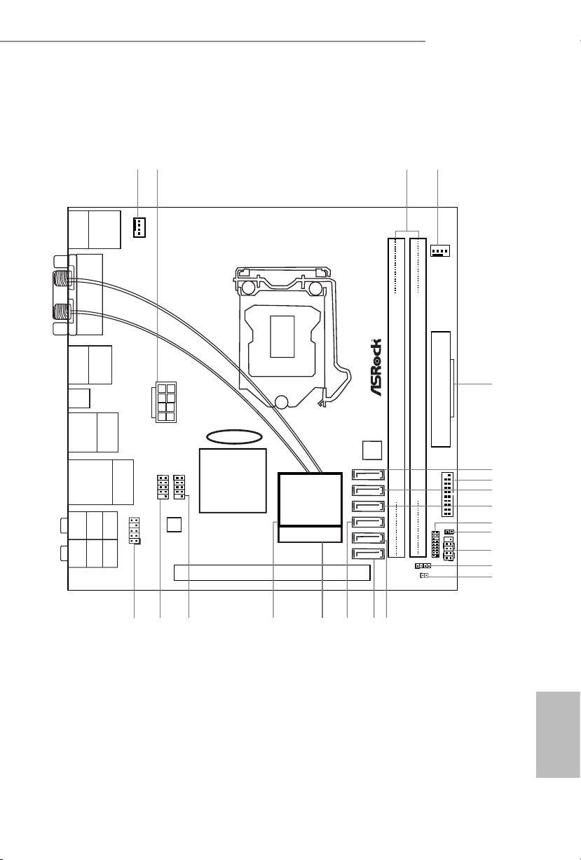
Motherboard Layout
Intel
Z87
PCIE1
DDR 3_A1 (6 4 bit, 24 0-pin m od ul e)
DDR 3_B1 (6 4 bit, 24 0-pin m od ul e)
64Mb
BIOS
HDLED RESE T
PLED PWRBT N
PANEL1
1
1
HD_AUDIO1
CHA_FAN1
CPU_FAN1
USB 2.0
T: USBA0
B: USBA1
DVI1
HDMI
DP_1
Clr
CMO S
USB 3.0
T: USB1
B: USB2
eSATA5
Top:
RJ-45
USB 3.0
T: USB3
B: USB4
Top:
CTR BAS S
Cente r:
REAR SP K
Botto m:
Optic al
SPDIF
Top:
LINE IN
Cente r:
FRONT
Botto m:
MIC IN
MINI_PCIE1
WiFi-802.11n
Module
3
4
ATXPWR1
5
22
Ro HS
H8 7E - IT X/a c
AUDIO
CODEC
ATX12V1
SATA3_5
SATA3_4
SATA3_3
SATA3_2
SATA3_1
SATA3_0
1 2
CMOS
Battery
USB3_5_6
1
TPMS1
1
SPEAKER1
CLRCMOS1
1
USB_2_31USB_4_5
1
6
8
9
12
7
16
15
17
13
14
20
21 18
19
10
1
CI1
11
PS2
Keyb oard
/Mou se
H87E-ITX/ac
English
1
Page 3
No. Description
1 CPU Fan Connector (CPU_FAN1)
2 ATX 12V Power Connector (ATX12V1)
3 2 x 240-pin DDR3 DIMM Slots (DDR3_A1, DDR3_B1)
4 Chassis Fan Connector (CHA_FAN1)
5 ATX Power Connector (ATXPWR1)
6 SATA3 Connector (SATA3_5) (shared with eSATA)
7 USB 3.0 Header (USB3_5_6)
8 SATA3 Connector (SATA3_4)
9 SATA3 Connector (SATA3_3)
10 TPM Header (TPMS1)
11 Chassis Intrusion Header (CI1)
12 System Panel Header (PANEL1)
13 Chassis Speaker Header (SPEAKER1)
14 Clear CMOS Jumper (CLRCMOS1)
15 SATA3 Connector (SATA3_1)
16 SATA3 Connector (SATA3_0)
17 SATA3 Connector (SATA3_2)
18 mini-PCI Express Slot (MINI_PCIE1)
19 WiFi-802.11n Module
20 USB 2.0 Header (USB_4_5)
21 USB 2.0 Header (USB_2 _3)
22 Front Panel Audio Header (HD_AUDIO1)
English
2
Page 4
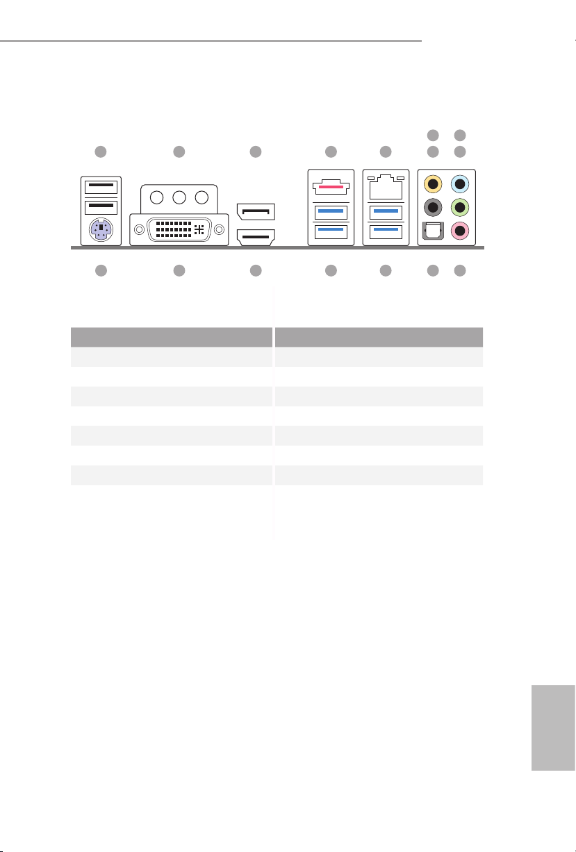
I/O Panel
1 2 3 754
No. Description No. Description
1 USB 2.0 Ports (USB01) 9 Front Speaker (Lime)**
2 Antenna Ports 10 Microphone (Pink)
3 Display Port 11 Optical SPDIF Out Port
4 eSATA Connector*** 12 USB 3.0 Ports (USB3_34)
5 LAN RJ-45 Port 13 USB 3.0 Ports (USB3_12)
6 Central / Bass (Orange) 14 HDMI Port
7 Rear Speaker (Black) 15 DVI-I Port
8 Line In (Light Blue) 16 PS/2 Keyboard Port
H87E-ITX/ac
698
10111213141516
English
3
Page 5
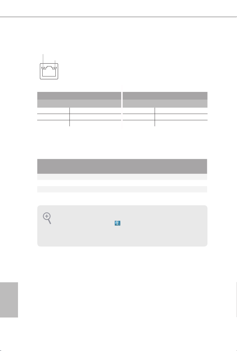
* ere are two LEDs on each LAN port. Please refer to the table below for the LAN port LED indications.
ACT/LINK LED
SPEED LED
LAN Por t
Activity / Link LED Speed LED
Status Description Status Description
O No Link O 10Mbps connection
Blinking Data Activity Orange 100Mbps connection
On Link Green 1Gbps connection
** If you use a 2- channel speaker, plea se connect the speake r’s plug into “Front Spea ker Jack”. See the table below
for connection d etails in accordance w ith the type of speaker you use.
English
Audio Output
Channels
Front Speaker
(No. 8)
Rear Speaker
(No. 6)
Central / Bass
(No. 5)
2 V -- -- --
4 V V -- --
6 V V V --
8 V V V V
To enable Multi-Streaming, you need to connect a front panel audio cable to the front
panel au dio header. Aer re starting your computer, you will nd the “Mixe r” tool on your
system. Plea se sele ct “Mixe r ToolBox” , click “Enable playback multi-streaming”, and
click “ok”. Choose “2CH”, “4CH”, “6CH”, or “8CH” and then you are a llowed to select
“Realtek HDA Primary output” to u se the Rear Speaker, Central/Ba ss, and Front Speaker,
or select “Realtek HDA Audio 2nd output” to use the front panel audio.
*** e eSATA connector is shared with SATA3_5 connec tor.
Line In
(No. 7)
4
Page 6
Chapter 1 Introduction
ank you for purchasing ASRock H87E-ITX/ac motherboard, a reliable
motherboard produced under ASRock’s consistently stringent quality control.
It delivers excellent performance with robust design conforming to ASRock’s
commitment to quality and endurance.
Becau se the motherboard specications and the BIOS soware might be updated, the
content of this documentation will be subject to change without notice. In case any modications of this manual occur, the updated version w ill be available on ASRock ’s website
without further notice. If you require technical suppor t related to this motherboard, pl ease
visit our website for specic information about the model you are using. You may nd the
latest VGA cards and CPU support list on ASRock ’s website a s well. ASRock website htt p://
www.asrock.com.
1.1 Package Contents
• ASRock H87E-ITX/ac Motherboard (Mini-ITX Form Factor)
• ASRock H87E-ITX/ac Quick Installation Guide
• ASRock H87E-ITX/ac Support CD
• 2 x Serial ATA (SATA) Data Cables (Optional)
• 1 x I/O Panel Shield
• 1 x ASRock WiFi 2.4/5GHz Antenna
H87E-ITX/ac
English
5
Page 7
1.2 Specications
Platform
A-Style
CPU
Chipset
Memory
• Mini-ITX Form Factor
• ASRock DuraCap (2.5 x longer life time) (100% Japan-made
high-quality conductive polymer capacitors)
• Home Cloud
• WiFi 802.11ac
• Supports 4th generation Intel® CoreTM i7 / i5 / i3 / Xeon® /
Pentium® / Celeron® in LGA1150 package
• Digi Power design
• 4 Power Phase design
• DrMOS
• Supports Intel® Turbo Boost 2.0 Technology
• Intel® H87
• Supports Intel® Small Business Advantage 2.0
• Dual Channel DDR3 Memory Technology
• 2 x DDR3 DIMM Slots
• Supports DDR3 1600/1333/1066 non-ECC, un-buered
memory
• Max. capacity of system memory: 16GB
(see CAUTION)
• Supports Intel® Extreme Memory Prole (XMP)1.3/1.2
English
6
Expansion
Slot
Graphics
• 1 x PCI Express 3.0 x16 Slot
• 1 x half mini-PCI Express Slot: For WiFi + BT module
• Intel® HD Graphics Built-in Visuals and the VGA outputs can
be supported only with processors which are GPU integrated.
• Supports Intel® HD Graphics Built-in Visuals : Intel® Quick
Sync Video with AVC, MVC (S3D) and MPEG-2 Full
HW Encode1, Intel® InTruTM 3D, Intel® Clear Video HD
Technology, Intel® InsiderTM, Intel® HD Graphics 4400/4600
• Pixel Shader 5.0, DirectX 11.1
• Max. shared memory 1792MB
Page 8

H87E-ITX/ac
Audio
LAN
• ree VGA output options: DVI-I, HDMI and DisplayPort
• Supports Triple Monitors
• Supports HDMI Technology with max. resolution up to 4K ×
2K (4096x2304) @ 24Hz
• Supports DVI-I with max. resolution up to 1920x1200 @
60Hz
• Supports DisplayPort with max. resolution up to 4K × 2K
(4096x2304) @ 24Hz
• Supports Auto Lip Sync, Deep Color (12bpc), xvYCC and
HBR (High Bit Rate Audio) with HDMI Port (Compliant
HDMI monitor is required)
• Supports HDCP with DVI-I, HDMI and DisplayPort Ports
• Supports Full HD 1080p Blu-ray (BD) / HD-DVD playback
with DVI-I, HDMI and DisplayPort Ports
• 7.1 CH HD Audio with Content Protection (Realtek ALC1150
Aud io Codec)
• Premium Blu-ray Audio support
• Gigabit LAN 10/100/1000 Mb/s
• Giga PHY Intel® I217V
• Supports Intel® Remote Wake Technology
• Supports Wake-On-LAN
• Supports Energy Ecient Ethernet 802.3az
• Supports PXE
Wireless
LAN
• Supports IEEE 802.11a/b/g/n/ac
• Supports Dual-Band (2.4/5 GHz)
• Supports high speed wireless connections up to 867Mbps
• 2 Antennas to support 2 (Transmit) x 2 (Receive) Diversity
Tech nolo gy
• Supports Bluetooth 4.0 / 3.0 + High speed class II
English
7
Page 9

Rear Panel
I/O
• 1 x PS/2 Mouse/Keyboard Port
• 1 x DVI-I Port
• 1 x HDMI Port
• 1 x DisplayPort
• 1 x Optical SPDIF Out Port
• 1 x eSATA Connector
• 2 x USB 2.0 Ports
• 4 x USB 3.0 Ports
• 1 x RJ-45 LAN Port with LED (ACT/LINK LED and SPEED
LED)
• HD Audio Jacks: Rear Speaker / Central / Bass / Line in /
Front Speaker / Microphone
English
Storage
Connector
BIOS
Feature
• 6 x SATA3 6.0 Gb/s Connectors, support RAID (RAID 0,
RAID 1, RAID 5, RAID 10, Intel Rapid Storage Technology
12 and Intel Smart Response Technology), NCQ, AHCI and
“Hot Plug” (SATA3_5 connector is shared with the eSATA
por t)
• 1 x eSATA Connector, supports NCQ, AHCI and “Hot Plug”
functions
• 1 x Chassis Intrusion Header
• 1 x TPM Header
• 1 x CPU Fan Connector (4-pin)
• 1 x Chassis Fan Connector (4-pin)
• 1 x 24 pin ATX Power Connector
• 1 x 8 pin 12V Power Connector (High Density Power
Connec tor)
• 1 x Front Panel Audio Connector
• 2 x USB 2.0 Headers (Support 4 USB 2.0 ports)
• 1 x USB 3.0 Header (Supports 2 USB 3.0 ports)
• 64Mb AMI UEFI Legal BIOS with multilingual GUI support
• ACPI 1.1 compliance wake up events
• SMBIOS 2.3.1 support
• CPU, DRAM, PCH 1.05V, PCH 1.5V Voltage multi-adjust-
ment
8
Page 10
H87E-ITX/ac
Support
CD
• Drivers, Utilities, AntiVirus Soware (Trial Version), Cyber-
Link MediaEspresso 6.5 Trial, Google Chrome Browser and
Toolbar, Start8, MeshCentral, Splashtop Streamer
Hardware
Monitor
• CPU/Chassis Temperature Sensing
• CPU/Chassis Tachometer
• CPU/Chassis Quiet Fan (Allow Chassis Fan Speed Auto-
Adjust by CPU Temperature)
• CPU/Chassis Fan Multi-Speed Control
• Voltage Monitoring: +12V, +5V, +3.3V, CPU Vcore
OS
Certications
* For detailed product information, please visit our website: http://www.asrock .com
Please realiz e that the re is a certain r isk involved with o verclocking, including adjusting
the setting in the BIOS, applying Untied Overclocking Technolog y, or using third-party
overclocking to ols. O verclocking may aect your system’s stability, or even c ause damage to
the components and devices of your system. It should be don e at your ow n risk and expense.
We are not responsibl e for possible damage caused by overclo cking.
• Microso® Windows® 8 / 8 64-bit / 7 / 7 64-bit compliant
• FCC, CE, WHQL
• ErP/EuP ready (ErP/EuP ready power supply is required)
Due to limitation , the actual memory size may be less than 4GB for the re servation for system usage under Windows® 32-bit ope rating systems. Windows® 64-bit operating systems
do not have s uch limitation s. You can use ASRock XFast R AM to utilize the memory that
Windows® cannot use.
English
9
Page 11
1.3 Unique Features
ASRock A-Tuning
A-Tuning is ASRock’s multi purpose soware suite with a new interface, more new
features and improved utilities, including XFast R AM, Dehumidier, Good Night
LED, FAN-Tastic Tuning, OC Tweaker and a whole lot more.
ASRock Instant Flash
ASRock Instant Flash is a BIOS ash utility embedded in Flash ROM. is conve-
nient BIOS update tool allows you to update the system BIOS in a few clicks without
preparing an additional oppy diskette or other complicated ash utility. Just save
the new BIOS le to your USB storage and launch this tool by pressing <F6> or
<F2> during POST to enter the BIOS setup menu to access ASRock Instant Flash.
Please be noted that the USB ash drive or hard drive must use FAT32/16/12 le
system.
ASRock APP Charger
Simply by installing the ASRock APP Charger makes your iPhone/iPad/iPod Touch
charge up to 40% faster than before on your computer. ASRock APP Charger allows
you to quickly charge many Apple devices simultaneously and even supports
continuous charging when your PC enters into Standby mode (S1), Suspend to RAM
(S3), hibernation mode (S4) or power o (S5).
ASRock XFast USB
ASRock XFast USB can boost the performance of your USB storage devices. e
performance may depend on the properties of the device.
English
10
ASRock XFast LAN
ASRock XFast LAN provides faster internet access, which includes the benets
listed below. LAN Application Prioritization: You can congure your application’s
priority ideally and add new programs to the list. Lower Latency in Game: Aer
setting online game’s priority higher, it can lower the latency in games. Trac
Shaping: You can watch Youtube HD videos and download simultaneously. Real-
Time Analysis of Your Data: With the status window, you can easily recognize
which data streams you are currently transferring.
Page 12
ASRock XFast RAM
ASRock XFast RAM is included in A-Tuning. It fully utilizes the memory space
that cannot be used under Windows® 32-bit operating systems. ASRock XFast RAM
shortens the loading time of previously visited websites, making web surng faster
than ever. And it also boosts the speed of Adobe Photoshop 5 times faster. Another
advantage of ASRock XFast RAM is that it reduces the frequency of accessing your
SSDs or HDDs in order to extend their lifespan.
ASRock Crashless BIOS
ASRock Crashless BIOS allows users to update their BIOS without fear of failing. If
power loss occurs during the BIOS updating process, ASRock Crashless BIOS will
automatically nish the BIOS update procedure aer regaining power. Please note
that BIOS les need to be placed in the root director y of your USB disk. Only USB 2.0
ports support this feature.
ASRock OMG (Online Management Guard)
Administrators are able to establish an internet curfew or restrict internet access
at specied times via OMG. You may schedule the starting and ending hours of
internet access granted to other users. In order to prevent users from bypassing
OMG, guest accounts without permission to modify the system time are required.
H87E-ITX/ac
ASRock Internet Flash
ASRock Internet Flash downloads and updates the latest UEFI rmware version
from our servers for you without entering Windows® OS. Please setup network
conguration before using Internet Flash.
ASRock UEFI System Browser
ASRock System Browser shows the overview of your current PC and the devices
connected.
ASRock Dehumidier Function
Users may prevent motherboard damages due to dampness by enabling
“Dehumidier Function”. When enabling Dehumidier Function, the computer
will power on automatically to dehumidify the system aer entering S4/S5 state.
ASRock Easy RAID Installer
ASRock Easy RAID Installer can help you to copy the RAID driver from the
support CD to your USB storage device. Aer copying the RAID driver to your
USB storage device, please change “SATA Mode” to “RAID”, then you can start
installing the OS in RAID mode.
English
11
Page 13
ASRock Easy Driver Installer
For users that don’t have an optical disk drive to install the drivers from our support
CD, Easy Driver Installer is a handy tool in the UEFI that installs the LAN driver
to your system via an USB storage device, then downloads and installs the other
required drivers automatically.
ASRock Interactive UEFI
ASRock Interactive UEFI is a blend of system conguration tools, cool sound eects
and stunning visuals. e unprecedented UEFI provides a more attractive interface
and more amusment.
ASRock Fast Boot
With ASRock’s exclusive Fast Boot technology, it takes less than 1.5 seconds to
logon to Windows 8 from a cold boot. No more waiting! e speedy boot will
completely change your user experience and behavior.
ASRock Restart to UEFI
Windows® 8 brings the ultimate boot up experience. e lightning boot up speed
makes it hard to access the UEFI setup. ASRock Restart to UEFI allows users to
enter the UEFI automatically when turning on the PC. By enabling this function,
the PC will enter the UEFI directly aer you restart.
ASRock Good Night LED
ASRock Good Night LED technology oers you a better sleeping environment by
extinguishing the unessential LEDs. By enabling Good Night LED in the BIOS, the
Power/HDD LEDs will be switched o when the system is powered on. Good Night
LED will automatically switch o the Power and Keyboard LEDs when the system
enters into Standby/Hibernation mode as well.
English
12
ASRock USB Key
In a world where time is money, why waste precious time everyday typing
usernames to log in to Windows? Why should we even bother memorizing those
foot long passwords? Just plug in the USB Key and let your computer log in to
windows automatically!
ASRock Home Cloud
is motherboard supports remote wake with the onboard Intel LAN, so you
can connect with your PC from anywhere in the world. You will be able to power
your PC on or turn it o, monitor and take control of it remotely with another
smartphone, tablet or computer.
Page 14

ASRock FAN-Tastic Tuning
ASRock FAN-Tastic Tuning is included in A-Tuning. Congure up to ve dierent
fan speeds using the graph. e fans will automatically shi to the next speed level
when the assigned temperature is met.
H87E-ITX/ac
13
English
Page 15
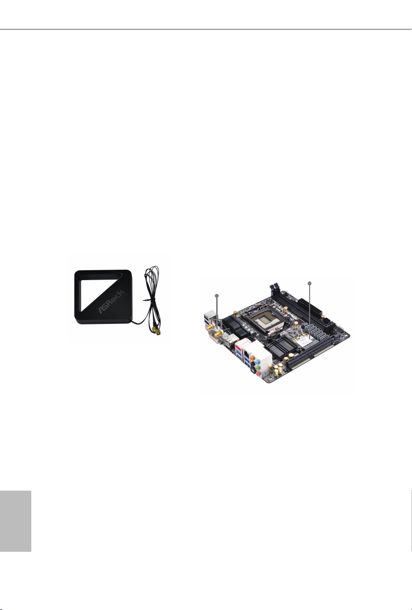
1.4 WiFi-802.11n Module and ASRock WiFi 2.4GHz Antenna
WiFi + BT Module
is motherboard comes with an exclusive WiFi 802.11 a/b/g/n/ac + BT v4.0
module that oers support for WiFi 802.11 a/b/g/n/ac connectivity standards and
Bluetooth v4.0. WiFi + BT module is an easy-to-use wireless loca l area network
(WLAN) adapter to support WiFi + BT. Bluetooth v4.0 standard features Smart
Ready technology that adds a whole new class of functionality into the mobile
devices. BT 4.0 also includes Low Energy Technology and ensures extraordinar y
low power consumption for PCs. e 2T2R WiFi solution sets a WiFi high speed
standard and oers max link rate up to 867Mbps.
* e transmission speed may vary according to the environment.
* e WiFi + BT module is supported under Windows® 8 / 8 64-bit / 7 / 7 64-bit
only.
WiFi + BT Module
Antenna Ports
ASRock WiFi 2.4GHz Antenna
English
14
Page 16

H87E-ITX/ac
Chapter 2 Installation
is is a Mini-ITX form factor motherboard. Before you install the motherboard,
study the conguration of your chassis to ensure that the motherboard ts into it.
Pre-installation Precautions
Take note of the following precautions before you install motherboard components
or change any motherboard settings.
• Make sure to unplug the power cord before installing or removing the motherboard.
Failure to do so may cause physical injuries to you and damages to motherboard
components.
• In order to avoid damage from static electricity to the motherboard’s components,
NEVER place your motherboard directly on a carpet. Also remember to use a grounded
wrist strap or touch a safety grounded object before you handle the components.
• Hold components by the edges and do not touch the ICs.
• Whenever you uninstall any components, place them on a grounded anti-static pad or
in the bag that comes with the components.
• When placing screws to secure the motherboard to the chassis, please do not over-
tighten the screws! Doing so may damage the motherboard.
15
English
Page 17
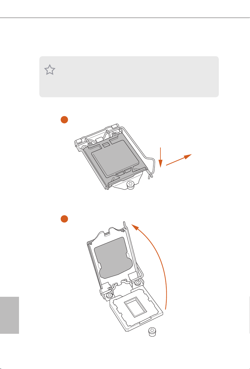
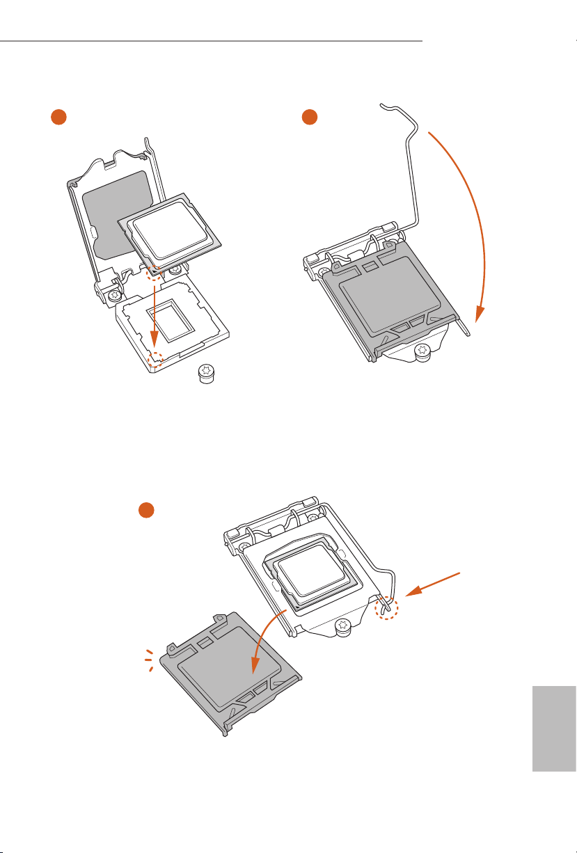
2.1 Installing the CPU
1. Before you insert the 1150-Pin CPU into the sock et, please check if the P nP cap is on the
socket, if the CPU surface is unclean, or if there are any bent pins in the sock et. Do not
force to in sert the CPU into the socket if above situation is found . Otherwise, the CPU
will be seriously damaged.
2. Unplug all power c ables before in stalling the CPU.
1
A
B
English
16
2
Page 18
H87E-ITX/ac
3
5
4
17
English
Page 19
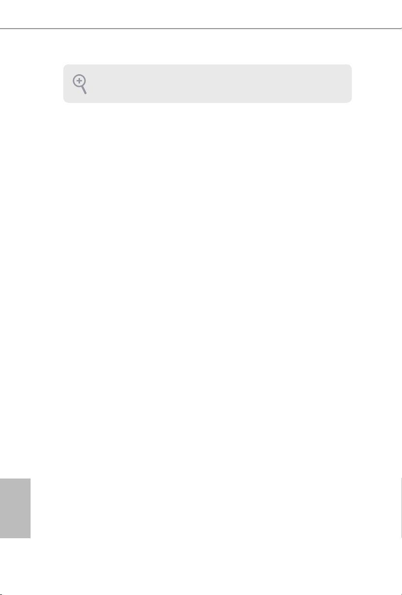
Please save and replace the cover if the processor i s removed. e cover must be placed if
you wish to return the motherboard for aer service.
English
18
Page 20
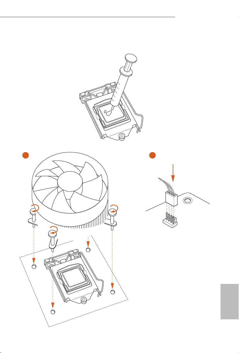
2.2 Installing the CPU Fan and Heatsink
1 2
H87E-ITX/ac
FAN
CPU_
English
19
Page 21
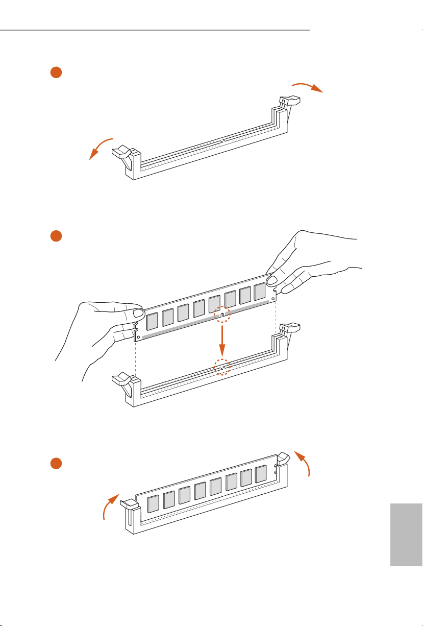
2.3 Installing Memory Modules (DIMM)
is motherboard provides two 240-pin DDR3 (Double Data Rate 3) DIMM slots,
and supports Dual Channel Memory Technology.
1. For dual channel cong uration , you always need to in stall identical (the same b rand,
speed , size and chip-type) DDR3 DI MM pairs.
2. It is unable to activate Du al Channel Memory Technology with only one memory module
installed.
3. It is not allowed to install a DDR or DDR2 memory module into a DDR3 slot; other wise,
this motherboard and DIMM may be damaged.
e DIMM only ts in one correct orie ntation. It will cause permanent dam age to the
motherboard and the DIMM if you force the DIMM into the slot at incorrect orientation.
English
20
Page 22
H87E-ITX/ac
1
2
3
English
21
Page 23
2.4 Expansion Slots (PCI and PCI Express Slots)
ere is 1 PCI Express slot and 1 mini-PCI Express slot on this motherboard.
Before installing an ex pansion card, please make sure that the power supply is switched o
or the power cord is unplug ged. Pl ease re ad the documentation of the expansion card and
make necessary hardware settings for the card before you start the installation.
PCIe slots:
PCIE1 (PCIe 3.0 x16 slot) is used for PCI Express x16 lane width graphics cards.
MINI_PCIE1 (mini-PCIe slot) is used for WiFi module.
English
22
Page 24
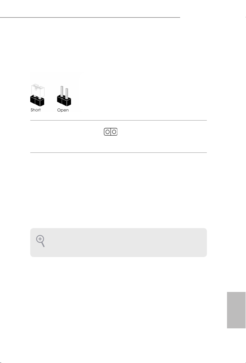
2.5 Jumpers Setup
e illustration shows how jumpers are setup. When the jumper cap is placed on
the pins, the jumper is “Short”. If no jumper cap is placed on the pins, the jumper is
“O pen”.
H87E-ITX/ac
Clear CMOS Jumper
(CLRCMO S1)
(see p.1, No. 14)
CLRCMOS1 allows you to clear the data in CMOS. e data in CMOS includes
system setup information such as system password, date, time, and system setup
parameters. To clear and reset the system parameters to default setup, please
turn o the computer and unplug the power cord, then use a jumper cap to short
the pins on CLRCMOS1 for 3 seconds. Please remember to remove the jumper
cap aer clearing the CMOS. If you need to clear the CMOS when you just nish
updating the BIOS, you must boot up the system rst, and then shut it down
before you do the clear-CMOS action.
1. e Clear CMOS Sw itch has the same f unction as the Clear CMOS jumper.
2. If you clear the CMOS, the ca se open may be detected . Please adju st the BIOS option “Cl ear
Status” to clear th e record of previous chassis intrusion status.
2-pin Jumper
Short: Clear CMOS
Open: Default
23
English
Page 25

2.6 Onboard Headers and Connectors
PWRBTN
Onboard headers and connectors are NOT jump ers. Do NOT place jumper caps over these
heade rs and connectors. Placing jumper caps over the headers and connectors will cause
permanent damage to the motherboard.
System Panel Header
(9-pi n PANEL1)
(see p.1, No. 12)
PWRBTN (Power Switch):
Connec t to the power switch on the ch assi s front panel. You may congure the way to tur n
o your system using the power switch.
RESET (Reset Switch):
Connec t to the reset switch on the chassi s front panel. Press the reset sw itch to restart the
computer if the computer f reezes and fails to per form a normal restar t.
PLED (Syste m Power LED):
Connec t to the power status indicator on the chas sis front panel. e LED i s on when the
system is operating. e LED keeps blinking when the system is in S1/S3 sleep state. e
LED is o when the system is in S4 slee p state or powered o (S5).
HDLED (Ha rd Drive Activity LED):
Connec t to the hard drive ac tivity LED on the chassis front panel. e LED is on when the
hard drive is reading or wr iting data.
e front panel de sign may dier by chassis. A front panel module mainly consists of powe r
switch, reset switch , power LED, hard dr ive activity LED, speaker and etc. When connecting your ch assi s front panel module to thi s header, make sure the wire a ssignments and the
pin assignments are matched correctly.
GND RESET#
PLED-
PLED+
GND
GND
#
HDLED-
HDLED+
1
Connect the power
switch, reset switch and
system status indicator on
the chassis to this header
according to the pin
assignments below. Note
the positive and negative
pins before connecting
the cables.
English
24
Page 26

H87E-ITX/ac
DUMMY
GNDGND
P+
P-
P+
P-
USB_PWR
USB_PWR
1
Serial ATA3 Connectors
(SATA3_0:
see p.1, No. 16)
(SATA3_1:
see p.1, No. 15)
(SATA3_ 2:
see p.1, No. 17)
(SATA3_ 3:
see p.1, No. 9)
(SATA3_4:
see p.1, No. 8)
(SATA3_ 5:
see p.1, No. 6)
USB 2.0 Headers
(9-pin USB_2_3)
(see p.1, No. 21)
(9-pin USB_4_5)
(see p.1, No. 20)
USB 3.0 Headers
(19-pin USB3_5_6)
(see p.1, No. 7)
Vbus
IntA_PA_SSRX-
IntA_PA_SSRX+
GND
IntA_PA_SSTX-
IntA_PA_SSTX+
GND
IntA_PA_D-
IntA_PA_D+
SATA3_5
SATA3_4
SATA3_3
SATA3_2
SATA3_1
SATA3_0
1
VbusVbus
IntA_PB_SSRX-
IntA_PB_SSRX+
GND
IntA_PB_SSTX-
IntA_PB_SSTX+
GND
IntA_PB_D-
IntA_PB_D+
Dummy
ese six SATA3
connectors support SATA
data cables for internal
storage devices with up
to 6.0 Gb/s data transfer
rate. SATA3_5 connector
is shared with the eSATA
port.
Besides two USB 2.0 ports
on the I/O panel, there
are two headers on this
motherboard. Each USB
2.0 header can support
two ports.
Besides four USB 3.0 ports
on the I/O panel, there
are one header on this
motherboard. Each USB
3.0 header can support
two ports.
English
25
Page 27

Front Panel Audio Header
MIC2_L
OUT_RE
1
SPEAKER
L
1
2
3
4
(9-pin HD_ AUDIO1)
(see p.1, No. 21)
1. High Denition Audio support s Jack Sensing, but the panel wire on the cha ssis must sup port HDA to function correctly. Ple ase fol low the instructions in our manual and chassis
manual to install your system.
2. If you use an AC’97 audio panel , please install it to th e front panel audio header by the
steps below:
A. Connect Mic_IN (MIC) to MIC2_ L.
B. Conne ct Audio_R (RIN) to OUT2_R and Audio_ L (LIN) to OUT2_ L.
C. Connect Ground (GND) to Ground (GND).
D. MIC_ RET and OUT_RET are for the HD audio panel only. You don’t ne ed to conn ect
them for the AC’97 audio panel .
E. To activate the front mic, go to the “FrontMic” Tab in the Realtek Control panel and
adjust “Recording Volume”.
PRESENCE#
MIC_RET
T
GND
OUT2_L
J_SENSE
1
is header is for
connecting audio devices
OUT2_R
to the front audio panel.
MIC2_R
English
26
Chassis Speaker Header
(4-p i n SPEAKER1)
(see p.1, No. 13)
Chassis and Power Fan
Connectors
(4-pin CHA_FAN1)
(see p.1, No. 4)
CPU Fan Connectors
(4-pin CPU_FAN1)
(see p.1, No. 1)
DUMMY
+5V
DUMMY
FAN_SPEED_CONTROL
CPU_FAN_SPEED
+12V
GND
GN D
+ 12V
CPU_FAN_SPEED
FAN_SPEED_CONTRO
Please connect the chassis
speaker to this header.
Please connect fan cables
to the fan connectors and
match the black wire to
the ground pin.
is motherboard pro-
vides a 4-Pin CPU fan
(Quiet Fan) connector.
If you plan to connect a
3-Pin CPU fan, please
connect it to Pin 1-3.
Page 28

H87E-ITX/ac
5
8
Signal
CK_33M_TPM
ATX Power Connector
(24-p i n ATX PWR1)
(see p.1, No. 5)
ATX 12V Power
Connector
(8-pin ATX12V1)
(see p.1, No. 2)
Chassis Intrusion Header
(2-p in CI1)
(see p.1, No. 11)
TPM Header
(17-pi n TP MS1)
(see p.1, No. 10)
12
1
SERIRQ#
S_PWRDWN#
GND
LAD1_L
LAD2_L
SMB_DATA_MAIN
SMB_CLK_MAIN
GND
24
is motherboard pro-
vides a 24-pin ATX power
connector. To use a 20-pin
ATX power supply, please
plug it along Pin 1 and Pin
13
1
13.
is motherboard pro-
vides an 8-pin ATX 12V
power connector. To use a
4
4-pin ATX power supply,
please plug it along Pin 1
and Pin 5.
1
GND
is motherboard supports
CASE OPEN de tec tion feat ure
th at d etect s if the cha ssis cove
has been removed. This feature
requires a chassis w ith chas sis
intrusion detection design.
GNDF_CLKRUN#
+3VSB
LAD0_L
+3V
LAD3_L
TPM_RST#
LFRAME#_L
1
is connector supports Trusted
Platform Module (TPM) system,
which can securely store keys,
digital certicates, passwords,
and data. A TPM system also
helps enhance network security,
protects digital identities, and
ensures platform integrity.
English
27
Page 29

한 국 어
1 개요
ASRock H87E-ITX/ac 마더보 드를 구입해 주셔서 감사합니다 . 이 마더보 드는
ASRock 의 일관되고 엄격한 품질관 리 하에 생산되어 신뢰성이 우수하며 , 품질과
내구 성에 대한 ASRock 의 기준에 부합하 는 우수한 성능과 견고한 설계를 제공합
니다 .
마더보드 규격과 BIOS 소프 트웨어를 업데이트할 수도 있기 때문에 , 이 문서의 내
용은 예고 없이 변경될 수 있습니다 . 이 설명서가 변경될 경우 , 업데이트된 버전은
ASRock 의 웹사 이트에 서 추가 통지 없이 제공 됩니다 . 이 마더보 드와 관련하여 기
술적 지원이 필요한 경우 , 당사의 웹사이트를 방문하여 사용 중인 모델에 대한 구체
적 정보를 구하십시오 . ASRock 의 웹사 이트에서는 최신 VGA 카드와 CPU 지원 목
록도 찾을 수 있습니다 . ASRock 웹사 이트 http://www.asrock.com.
1.1 포장 내용물
• ASRock H87E-ITX/ac 마더보드 (Mini-ITX 폼팩터 )
• ASRock H87E-ITX/ac 간편 설치 안내서
• ASRock H87E-ITX/ac 지원 CD
• 시리얼 ATA (SATA) 데이터 케이블 2개 ( 선택 품목 )
• I/O 패널 실드 1 개
• ASRock WiFi 2.4GHz 안테나 1 개
28 29
Page 30

1.2 규격
H87E-ITX/ac
플랫폼
CPU
칩세트
메모리
확장 슬롯
• Mini-ITX 폼 팩터
• ASRock DuraCap (2.5 배 길어진 수명 ) (100% 일본산 고품 질
전도성 폴리머 콘덴서 )
• LGA115 0 패키지로 제공되는 4 세대 Intel® CoreTM i7 / i5 / i3 /
Xeon® / Pentium® / Celeron® 지원 Digi 전원 구조
• 4 개 전원 위상 구조
• DrMOS
• Intel® Turbo Boost 2.0 기술 지원
• Intel® H87
• Intel® Small Business Advantage 2.0 지원
• 듀얼 채널 DDR3 메모리 기술
• DDR3 DIMM 슬롯 2 개
• DDR3 1600/1333/1066 비 -ECC, 비버퍼링 메모리 지원
• 시스템 메모리 최대 용량 : 16GB
( 주의 참조 )
• Intel® Extreme Memory Prole (XMP)1.3/1.2 지원
• PCI Express 3.0 x16 슬롯 1 개
• 하프 mini-PCI Express 슬롯 1 개 : WiFi + BT 모듈용
한 국 어
그래픽
• Intel® HD 그래픽스 빌트 - 인 비주얼과 VGA 출력은 GPU 통
합 프 로세서 로만 지원할 수 있습니다 .
• Intel® HD 그래픽스 빌트 - 인 비주얼 지원 : AVC, MVC (S3D)
및 MPE G-2 풀 HW Encode1 지원 Intel® Quick Sync Video,
Intel® InTruTM 3D, Intel® 클리어 비디오 HD 기술 , Intel®
InsiderTM, Intel® HD 그래픽스 4400/4600
• Pixel Shader 5.0, DirectX 11.1
• 최대 공유 메모리 1792MB
Page 31

• VGA 출력 옵션 세 개 : DVI-I, HDMI 및 DisplayPort
• 삼중 모니터 지원
• HDMI 기술 지원 ( 최대 해상도 4K × 2K (4096x2304) @
24Hz)
• DVI-I 지원 ( 최대 해상도 1920x1200 @ 60Hz)
• DisplayPort 지원 ( 최대 해상도 3840x2160 @ 60Hz)
• Auto Lip Sync, Deep Color (12bpc), xvYCC 및 HBR (High Bit
Rate Audio)(HDMI 포함 ) 지원 (HDMI 호환 모니터 필요 )
• DVI-I, HDMI 및 DisplayPort 포트를 이용한 HDCP 기능 지원
• DVI-I, HDMI 및 DisplayPort 포 트를 이용한 Full HD 1080p
Blu-ray (BD) / HD-DVD 재생 지원
한 국 어
오디오
LAN
무선 LAN
• 콘텐츠 보 호를 이용한 7.1 CH HD 오디오 지원 (Realtek
AL C1150 오디오 코덱 )
• 프리미엄 Blu-ray 오디오 지원
• Gigabit LAN 10/100/10 00 Mb/s
• Giga PHY Intel® I217 V
• Intel® 리모트 웨이크 기술 지원
• Wake-On-L AN 지원
• 절전형 이더넷 802.3az 지원
• PXE 지원
• IEEE 802.11a/b/g/n/ac 지원
• 듀얼 밴드 (2.4/5 GHz) 지원
• 최대 867Mbps 의 고속 무선 연결 지원
• 2 ( 송신 ) x 2 ( 수신 ) 다 이버시티 기술 지원용 안테나 2 개
• Bluetooth 4.0 / 3.0 + 고속 클래스 II 지원
30 31
Page 32

H87E-ITX/ac
후면 패널 I/O
저장 장치
커넥터
• PS 1 개 / 마우스 / 키보 드 포트 2 개
• DVI-I 포트 1 개
• HDMI 포트 1 개
• DisplayPort 1 개
• 광학 SPDIF 출력 포트 1 개
• eSATA 커넥터 1 개
• USB 2 포트 2 개
• USB 4 포트 3.0 개
• LED 장착 RJ-45 LAN 포트 1 개 (ACT/LINK LED 및 SPEED
LED)
• HD 오디오 잭 : 후면 스피커 / 중앙 / 베이스 / 라인 입력 / 전
면 스피커 / 마이크
• SATA3 6.0 Gb/s 커넥터 6 개가 RAID (RAID 0, RAID 1,
RAID 5, RAID 10, Intel 빠른 스토리지 기술 12 및 Intel 스
마트 응답 기술 ), NCQ, AHCI 및 “핫 플 러 그”를 지원
(SATA3_ 5 커넥터는 eSATA 포트와 공 유되며 )
• eSATA 커넥터 1 개 , NCQ, AHCI 및 “핫 플 러 그” 기능 지원
• 섀시 침입 헤더 1 개
• TPM 헤더 1 개
• CPU 팬 커넥터 1 개 (4 핀 )
• 섀시 팬 커넥터 1 개 (4 핀 )
• 24 핀 ATX 전원 커넥터 1 개
• 8 핀 12V 전원 커넥터 1 개 ( 고밀도 전원 커넥터 )
• 전면 패널 오디오 커넥터 1 개
• USB 2.0 헤더 2 개 (USB 2.0 포트 4 개 지원 )
• USB 3.0 헤더 1 개 (USB 3.0 포트 2 개 지원 )
한 국 어
BIOS 기능
• 다국어 GUI 지원을 제공하 는 64Mb AMI UEFI 적합형 BIOS
• ACPI 1.1 준수 웨이크 업 이벤트
• SMBIOS 2.3.1 지원
• CPU, DRAM, PCH 1.05V, PCH 1.5V 전압 다중 조정
Page 33

지원 CD
• 드라이버 , 유틸리티 , 백신 소 프트웨어 ( 시험판 ), CyberLink
MediaEspresso 6.5 시험판 , Google Chrome 브라우저 및 툴
바 , Start8, MeshCentral, Splashtop Streamer
한 국 어
하드웨어 모니
터
• CPU/ 섀시 온도 감지
• CPU/ 섀시 타코미터
• CPU/ 섀시 저소음 팬 (CPU 온도에 의한 섀시 팬 속도 자동
조정 )
• CPU/ 섀시 팬 다중 속도 조절
• 전압 모니터링 : +12V, +5V, +3.3V, CPU Vcore
OS
인증
• Microso® Windows® 8 / 8 64 비트 / 7 / 7 64 비트 호환
• FCC, CE, WHQL
• ErP/ EuP 사용 가능 (ErP/EuP 사용 가능 전원공급장치 필요 )
* 자세한 제품 정 보에 대해서는 당사 웹사 이트를 참조하십시오 : http://www.asrock.com
BIOS 설정을 조 정하거나 Untied Overclocking Technology 를 적용 하거나 타업체의
오버클로킹 도구 를 사용하는 것을 포함 하 는 오 버클로킹에는 어느 정도의 위험이
따른다는 것을 유념하 십시오 . 오버클로 킹은 시 스템 안정성에 영향 을 주거나 심지
어 시스템의 구성 요 소와 장치에 손상을 입힐 수도 있습 니다 . 오버클로킹은 사 용자
스스로 위험과 비용 을 감 수하고 해야 합니다 . 당사는 오 버클로 킹에 의해 발생할 수
있는 손상에 대해서 책임이 없습니다 .
제한 때문에 실제 메모리 크기는 Windows® 32 비트 운영체 제 하의 시스템 사용을
위한 예비 메모리용 4GB 보다 더 적을 수 있습니다 . Windows® 6 4 비트 운 영체제
에는 그러한 제한이 없습니다 . ASRock X Fast RAM 을 사 용하여 Windows® 가 사
용할 수 없는 메모리를 이용할 수 있습니다 .
32 33
Page 34

1.3 점퍼 설정
그림은 점퍼를 어떻게 설정하는지 보여줍니다 . 점퍼 캡을 핀에 씌우면 점퍼가 “단
락”됩 니 다 . 점퍼 캡을 핀에 씌우지 않으면 점퍼가 “ 단 선”됩 니 다 .
H87E-ITX/ac
Clear CMOS 점퍼
(CLRCMO S1)
(1 페이지 , 14 번 항목 참조 )
2 핀 점퍼
단락 : Clear CMOS
단선 : 기본 값
CLRCMOS1 을 사용하여 CMOS 에 저장된 데이터를 지울 수 있습니다 . CMOS
에 저장된 데이터에는 시스템 암호 , 날짜 , 시간 및 시스템 설정 파라미터와 같
은 시스템 설정 정보가 포함됩니다 . 시스템 파라미터를 지우고 기본 설정으
로 초기화하려면 컴퓨터를 끄고 전원 코 드를 뽑은 다음 점퍼 캡을 사용하여
CLRCMOS1 의 핀을 3 초 동안 단락시키시십오 . CMOS 를 지운 후 반드 시 점퍼
캡을 제거하십시오 . BIOS 업데이트를 완료한 직후 CMOS 를 지워야 할 경우 , 우
선 시스템을 부팅한 후 바이오 스 업데이트를 종료한 다음 CMOS 지우기 작업을
해야 합니다 .
1.
Clear CMOS 스위치는 Clear CMOS 점퍼와 동일한 기능을 갖고 있습니다 .
2.
CMOS 를 지울 경우 케이스 열림이 감지될 수도 있습니다 . BIOS 옵션 “Clear
Status( 상태 지우기 )”를 조절하 여 이전의 섀시 침입 상태에 대한 기록 을 지우
십시오 .
한 국 어
Page 35

1.4 온보드 헤더 및 커넥터
온보드 헤더와 커넥터는 점퍼가 아닙니다 . 점퍼 캡을 온보드 헤더와 커 넥터에 씌우
지 마십시오 . 점퍼 캡을 온보 드 헤더와 커넥터에 씌우면 마더보드가 영구적으로
손상됩니다 .
한 국 어
시스템 패널 헤더
(9 핀 PA NE L1)
(1 페이지 , 12 번 항목 참조 )
PWRBT N( 전원 스위치 ):
섀시 전면 패널의 전원 스위치에 연결합니다 . 전원 스위치를 이용해 시스템을 끄는
방법을 구성할 수 있습니다 .
RESE T( 리셋 스위치 ):
섀시 전면 패널의 전원 스위치에 연결합니다 . 컴퓨터가 정지하고 정상적 재시작을
수행하지 못할 경우 리셋 스위치를 눌러 컴퓨터를 재시작합니다 .
PLED( 시스템 전원 LED):
섀시 전면 패널의 전원 상태 표시등에 연결합니다 . 시스템이 작 동하고 있을 때는
LED 가 켜져 있습니다 . 시스템 이 S1/S3 대기 상태에 있을 때는 LED 가 계속 깜박입
니다 . 시스템이 S4 대기 상태 또는 전원 꺼짐 (S5) 상태에 있을 때는 LED 가 꺼져 있
습니다 .
HDLED( 하드 드라이브 동작 LE D):
섀시 전면 패널의 하드 드라이브 동작 LED 에 연결합니다 . 하드 드라이브 가 데이
터를 읽거나 쓰고 있을 때 LED 가 켜져 있습니다 .
전면 패널 디자인은 섀시별로 다를 수 있습니다 . 전면 패널 모듈 은 주로 전원 스위
치 , 리셋 스위치 , 전원 LED, 하드 드라 이브 동작 LE D, 스피커 등으로 구 성되어 있
습니다 . 섀시 전면 패널 모듈 을 이 헤더에 연결할 때 와 이어 할당과 핀 할당이 정확
히 일치하는지 확인합 니다 .
GND RESET#
PWRBTN#
PLED-
PLED+
GND
GND
HDLED-
HDLED+
1
섀시의 전원 스위치 , 리
셋 스위치 , 시스템 상태
표시등을 아래의 핀 할
당에 따라 이 헤더에 연
결합니다 . 케이블을 연
결하기 전에 양극 핀과
음극 핀을 기록합니다 .
34 35
Page 36

H87E-ITX/ac
DUMMY
GNDGND
P+
P-
P+
P-
USB_PWR
USB_PWR
1
1
시리얼 ATA3 커넥터
(SATA3_0:
1페이지 , 16 번 항목 참조 )
(SATA3_1:
1페이지 , 15 번 항목 참조)
(SATA3_ 2:
1페이지 , 17 번 항목 참조 )
(SATA3_ 3:
1 페이지 , 9 번 항목 참조 )
(SATA3_4:
1 페이지 , 8 번 항목 참조 )
(SATA3_ 5:
1 페이지 , 6 번 항목 참조 )
USB 2.0 헤더
(9 핀 USB_2_3)
(1 페이지 , 21 번 항목 참조)
(9 핀 USB_4_5)
(1 페이지, 20 번 항목 참조 )
USB 3.0 헤더
(19 핀 USB3_5_6)
(1 페이지 , 7 번 항목 참조 )
Vbus
IntA_PA_SSRX-
IntA_PA_SSRX+
GND
IntA_PA_SSTX-
IntA_PA_SSTX+
GND
IntA_PA_D-
IntA_PA_D+
SATA3_5
SATA3_4
SATA3_3
SATA3_2
SATA3_1
SATA3_0
VbusVbus
IntA_PB_SSRX-
IntA_PB_SSRX+
GND
IntA_PB_SSTX-
IntA_PB_SSTX+
GND
IntA_PB_D-
IntA_PB_D+
Dummy
이들 6 개의 SATA3 커
넥터는 최대 6.0 Gb/s 데
이터 전송 속도를 제공
하는 내부 저장 장치용
SATA 데이터 케이블 을
지원합니다 . SATA3_5
커넥터는 eSATA 포트와
공유되며 .
I/O 패널에 USB 2.0 포
트 두 개가 탑재되어 있
을 뿐 아니라 마더보드
에 헤더 두 개가 탑재되
어 있습니다 . 각 USB 2.0
헤더는 포트 두 개를 지
원할 수 있습니다 .
I/O 패널에 USB 3.0 포트
네 개가 탑재되어 있을
뿐 아니라 마더보 드에
헤더 한 개가 탑재되어
있습니다 . 각 USB 3.0 헤
더는 포트 두 개를 지원
할 수 있습니다 .
한 국 어
Page 37

한 국 어
MIC2_L
OUT_RE
CPU_
FAN_SPEED_CONTROL
1
DUMMY
SPEAKER
L
1
2
3
4
전면 패널 오디오 헤더
(9 핀 HD_AUDIO1)
(1 페이지 , 21 번 항목 참조)
1.
고음질 오디오는 잭 감지를 지원하지만 올바르 게 작 동하려면 섀시의 패널 와이어
가 HDA 를 지원해야 합니다 . 설명서 및 섀시 설명서에 나와 있는 지침을 따라 시
스템을 설치하 십시오 .
2.
AC’97 오디오 패널을 사 용할 경우 아 래와 같은 절차 를 따라 전면 패널 오디오
헤더에 설치하십시오 :
A. Mic_IN (M IC) 을 MIC2_L 에 연결합니다 .
B. Audio_R (RI N) 을 OUT2_ R에 연결하고 Aud io_L (LIN) 을 OUT2 _L 에 연결
합니다 .
C. 접지 (GN D) 를 접지 (GND) 에 연결합니다 .
D. MIC_ RET 및 OUT_RET 는 HD 오디오 패널에만 사용 됩니다 . AC’97 오디오
패널용으로 연결할 필요 가 없습니다 .
E. 전면 마 이크를 활 성화하 려면 Realtek 제어판에서 “FrontMic” 탭으 로 가서
“Recording Volume( 녹음 볼륨 )”을 조정합 니다 .
PRESENCE#
MIC_RET
T
GND
OUT2_L
J_SENSE
OUT2_R
1
이 헤더는 오디오 장치
를 전면 오디오 패널에
연결하는 데 사 용 됩니
MIC2_R
다 .
36 37
섀시 스피커 헤더
(4 핀 SPE AK ER1)
(1 페이지 , 13 번 항목 참조 )
섀시 및 전원 팬 커넥터
(4 핀 C H A _ FA N1)
(1 페이지 , 4 번 항목 참조 )
CPU 팬 커넥터
(4 핀 C PU_ FAN1)
(1 페이지 , 1 번 항목 참조 )
DUMMY
+5V
FAN_SPEED
+12V
GND
GN D
+ 12V
CPU_FAN_SPEED
FAN_SPEED_CONTRO
섀시 스피커를 이 헤더
에 연결하십시오 .
팬 케이블을 팬 커넥터
에 연결하고 검은색 와
이어를 접지핀에 연결하
십시오 .
이 마더보 드에는 4 핀
CPU 팬 ( 저소음 팬 ) 커
넥터가 탑재되어 있습니
다 . 3 핀 CPU 팬을 연결
하려는 경우 핀 1-3 에 연
결하십시오 .
Page 38

H87E-ITX/ac
5
8
Signal
CK_33M_TPM
SMB_DA
ATX 전원 커넥터
(24 핀 ATXPWR1)
(1 페이지 , 5 번 항목 참조 )
ATX 12V 전원 커넥터
(8 핀 AT X12V1)
(1 페이지 , 2 번 항목 참조 )
섀시 침입 헤더
(2 핀 CI1)
(1 페이지 , 11 번 항목 참조 )
TPM 헤더
(17 핀 T PMS1)
(1 페이지 , 10 번 항목 참조 )
12 124
1
SERIRQ#
S_PWRDWN#
GND
LAD1_L
LAD2_L
TA_MAIN
SMB_CLK_MAIN
GND
GND
13
1
4
1
GNDF_CLKRUN#
+3VSB
LAD0_L
+3V
LAD3_L
TPM_RST#
LFRAME#_L
이 마더보 드에는 24 핀
ATX 전원 커넥터가 탑
재되어 있습니다 . 20 핀
ATX 전원공급장치를 사
용하려면 핀 1 과 핀 13
을 따라 연결하십시오 .
이 마더보 드에는 8 핀
ATX 12V 전원 커넥터가
탑재되어 있습니다 . 4 핀
ATX 전원공급장치를 사
용하려면 핀 1 과 핀 5 을
따라 연결하십시오 .
이 마더보 드는 섀시 커버가 제
거될 경우 이를 감지하는 케이
스 열림 감지 기능 을 지원합니
다 . 이 기능 을 사용하려면 섀시
침입 감지 설계가 적용 된 섀시
를 사용해야 합 니다 .
이 커넥터는 키 , 디지털 인증
서 , 암호 및 데이터를 안전하게
보관할 수 있는 T PM(Trusted
Platform Module) 시스템 을 지
원합니다 . TPM 시스템은 네트
워크 보안 을 강화하고 , 디지털
신원을 보 호하며 플랫폼 무결
성을 유지합니다 .
한 국 어
Page 39

日本語
1 はじめに
アスロックの一貫した 厳 格な品 質 管 理の下 で製 造された信 頼 性 の高いマザー
ボードで あ るア スロック H87E-ITX /ac マザーボードをお買い上げいただきありが
とうござ いま す。 アスロックの品質と耐久性の取り組み に準拠した堅牢な設 計を
持 つ 、優 れ た パ フ ォ ー マ ン ス を 提 供 し ま す 。
マ ザ ーボ ード の 仕 様と BIOS ソフトウェアは更 新されることがあ るため 、このマニ ュ
アルの内容は予告なしに変更することがあります。 このマニュアルの内 容 に 変 更
があった場合には、更新されたバージョンは、予告なくアスロックのウェブサイト
から 入手 で き るように なりま す。 このマ ザ ーボ ード に 関 する技 術 的 な サ ポ ートが
必要な場 合には、ご使用のモデルについての詳細情報を、当社のウェブサイトで参
照くだ さい。 ア ス ロ ッ ク の ウ ェ ブ サ イ ト で は 、最 新 の VG Aカ ード お よび CPU サポー
ト一 覧もご 覧 に な れ ま す。 ア ス ロック ウェ ブ サイト http://www.asrock.com.
1.1 パッケ ージの 内 容
• アスロック H87E-I TX/ac マ ザ ー ボ ー ド( ミ ニ ITX フォ ームフ ァクター )
• アスロック H87E-I TX/ac クイックインストールガイド
• アスロック H87E-I TX/ac サ ポ ート CD
2 x
•
シリアル ATA(SATA)デ ー タ ケ ー ブ ル( オ プ シ ョ ン )
• 1 x I/O パ ネ ル シ ールド
• 1 x アスロック WiFi 2.4GHz アンテナ
38
Page 40

1.2 仕様
H87E-ITX/ac
プ ラ ットフ ォ ー ム
CPU
チップ セ ット
メモリ
拡 張 スロット
• ミニ ITX フォ ーム ファクタ ー
• アスロックデュラキャップ(2.5 倍 の 長 寿 命 )( 100% 日本 製
の 高品質導電性高分子コンデンサー)
• LGA115 0 パ ッ ケ ー ジ で は 、第 4 世代の Intel® CoreTM i7 / i5 /
i3 / Xeon® / Pentium® / Celeron® を サ ポート
• デジタル電 源 設 計
• 4 電 源 フェーズ 設 計
Dr. MOS
•
• Intel®ターボブースト 2.0 テ クノ ロ ジ ー を サ ポ ー ト
• Intel® H87
• Intel® スモールビジネスアドバンテージ 2.0 を サポ ート
• デュアル チ ャン ネ ル DDR3 メモリテクノロジー
• 2 x DDR3 DIMM ス ロ ット
• DDR3 1600/1333/1066 ECC なし 、アンバッファードメモリを
サポート
• システム メモリの 最 大 容 量: 16GB
(注意を参 照)
• Intel®エクストリームメモリプロファイル(XMP)1.3/1.2
を サ ポ ート
• 1 x PCI Express 3.0 x16 スロット
• 1 x ハーフミニ PCI Express ス ロ ッ ト: WiFi + BT モジュール
用
日本語
グラフィッ クス
• Intel®HDグ ラフィッ クス 内 蔵 ビ ジュアル お よび VGA 出力は、
GPU に統 合されたプロセッサ ー のみで サ ポートされます。
• Intel®HD グラフィックス内蔵ビジュアルを サポート: AVC、
MVC (S3D)、MPEG-2 フル HW エンコ ード 1 の Intel® Quick
Sync Video、Intel® InTruTM 3D、Intel® クリアビデ オ HD テク
ノロジー 、Intel® イン サ イダ ーTM、Intel® HD グラフィ ックス
4400/4600
• ピクセ ル シェー ダー 5.0、DirectX 11.1
• 最 大 共 有メモリ 1792MB
39
Page 41

日本語
• 3 つの VGA 出 力 オプション: DVI-I、HDMI、デ ィ ス プ レ イ
ポート
•3台の モニターをサポート
• HDMI テ クノ ロ ジ ー を サ ポ ー ト 。 最大解像度 4K × 2K
(4096x2304)@24Hz
• DVI-I を サ ポート。 最大解像度 1920x1200 @60Hz
• ディスプ レイポ ート を サポート。 最大解像度 384 0x2160
@60Hz
• HDMI(HDMI 準 拠 の モニターが必要)では、オートリップ
シ ン ク 、デ ィ ー プ カ ラ ー ( 12bpc)、x vYCC、HBR( 高 ビットレ
ートオ ー ディオ)をサ ポ ート
• DVI-I、HDMI、デ ィ ス プ レ イ ポ ー ト で 、 HDCP 機能をサポー
ト
• DVI-I、HDMI、デ ィ ス プ レ イ ポ ー ト で 、フ ル HD 1080pブル
ーレイ (BD) / HD-DVD 再 生 を サ ポ ート
音声
LAN
ワイヤレス LAN
• 7.1 CH HD オーディオ、コンテンツプロテクション付き
(Realte k A LC1150 オーディオコーデック)
• プレミアムブルーレイオーディオサポート
• ギ ガ ビット L AN 10/10 0/1000 Mb/ 秒
• ギガ PHY Intel® I217V
• Intel® リモ ートウェイクテクノ ロジ ー を サ ポート
• ウェ イク オン ラ ン を サ ポ ー ト
• エネルギー効率のよいイーサネット 802.3az を サポート
• PXE を サ ポ ート
• IEEE 802.11a/b/g/n/ac をサポート
• デ ュ ア ル バ ン ド( 2.4/5 GHz)を サ ポ ー ト
• 最高 867Mbps の高速ワイヤレス接続をサポート
• 2(送信) x 2(受信)ダイバーシティテクノロジーをサポー
トする 2 本 のアンテナ
• ブル ートゥ ース 4.0/3.0 + ハ イスピードクラス II を サ ポ ート
40
Page 42

H87E-ITX/ac
リアパ ネ ル I/O
ストレ ー ジ
コネクター
• 1 x PS/2 マウス / キ ーボードポート
• 1 x DVI-I ポート
• 1 x HDMI ポ ート
• 1 x ディスプ レ イポ ート
• 1 x 光 SPDIF 出 力 ポート
• 1 x eSATA コ ネクター
• 2 x USB 2.0 ポ ート
• 4 x USB 3.0 ポート
• LED 付き 1 x RJ-45 LAN ポ ー ト( ACT/LINK LEDと SPEED
LED)
• HD オ ー ディ オ ジ ャ ッ ク: リア スピーカー / センター / バス /
ラインイン / フ ロ ントス ピ ー カ ー / マ イク
• 6 x SATA3 6.0 Gb/ 秒コネクター 、RAID サ ポ ー ト( R AID 0、
RAID 1、RAID 5、R AID 10、Intel ラピ ッ ド ス ト レ ー ジ テ クノ
ロジー 12、Intel ス マ ー ト レ ス ポ ン ス テ クノ ロ ジ ー )、NCQ、
AHCI、「 ホ ッ ト プ ラ グ 」( eSATA ポ ートと 共 有の SATA3_5
コネクター)
• 1 x eSATA コ ネクター 、NCQ、AHCI、「 ホ ッ ト プ ラ グ 」 機 能
を サ ポ ート
• 1 x シャーシイントルージョンヘッダー
• 1 x TPM ヘッダー
• 1 x CPU フ ァン コ ネ ク タ ー( 4 ピン)
• 1 x シ ャ ー シ フ ァン コ ネ ク タ ー( 4 ピン)
• 1 x 24 ピン ATX 電 源コネクター
• 1 x 8 ピン 12V 電 源コネクター( 高 密 度 電 源 コ ネクター)
• 1 x 前 面 パ ネ ル オ ー ディオ コ ネクター
• 2 x USB 2.0 ヘ ッ ダ ー( 4 つの USB 2.0 ポ ートを サ ポート)
• 1 x USB 3.0 ヘ ッ ダ ー( 2 つの USB 3.0 ポ ート を サポート)
日本語
BIOS 機能
• 多言語 GUI サ ポート付 きの 64Mb AMI UEFI Legal BIOS
• ACPI 1.1 準 拠 のウェイクアップイベント
• SMBIOS 2.3.1 をサ ポ ート
• CPU、DRAM、PCH 1.05V、PCH 1.5V 複数電圧設定
41
Page 43

サ ポ ート CD
• ドラ イバ ー 、ユー ティリティ、ア ン チウイルスソフトウェ ア
( ト ラ イ ア ル 版 )、CyberLink MediaEspresso 6.5トライ
アル、Google Chrome ブラウザー、ツールバー、Start8、
MeshCentra l、Splashtop Streamer
日本語
ハードウェアモ
ニター
• CPU/ シャ ーシ 温度センサー
• CPU / シャーシタコメーター
• CPU/ シ ャ ー シ 静 音 フ ァ ン( CPU 温 度 によるシ ャ ーシファン
速度の自動調整可能)
• CPU/ シ ャ ーシ ファン マル チ 速 度 制 御
• 電 圧 監 視: +12V、+5V、+3.3V、C PU Vc ore
OS
認証
• Microso® Windows® 8 / 8 64 ビット / 7 / 7 64 ビット 準 拠
• FCC、CE、WHQL
• ErP/EuP Ready(ErP/Eu P rea dy 電源が必 要です)
* 商品詳細については、当社ウェブサイトをご覧ください。 http://www.asrock.com
BIOS 設定の調整、アンタイドオーバークロックテクノロジーの適 用、サードパ ーティ
のオーバークロックツールの 使用などを 含む、オーバークロックには、一定のリス
クを 伴 います のでご 注 意くだ さ い。 オーバ ークロックするとシステムが不 安 定に
なったり、システムのコンポ ーネントや デバ イスが 破 損することがあります。 ご自
分 の 責 任 で 行 ってくだ さ い 。 弊 社では、オーバークロックによる破損の責任は負
いか ね ま すのでご 了承くださ い 。
Windows® 32 ビットオペレ ー ティングシステムでの 、システム使 用に 割り当 てら れ
た実 際 のメモリサイズは制 限 のた め、4GB 未 満 の こと が ありま す。 Windows®
64 ビットの オペレ ーティングシステムで は 、そ の ような 制限 は ありま せ ん 。
Windows® では使 えな いメモリを使 用するために 、アスロック XFast RAM を使用
すること が で き ま す。
42
Page 44

1.3 ジャンパ ー 設 定
このイラストは、ジャンパー の設定 方法を 示しています。 ジャン パ ー キ ャッ プ が ピ
ンに被さって いると、ジャンパーは「ショート」です。 ジャン パ ー キ ャップ が ピ ン に
被 さ っ て い な い 場 合 に は 、ジ ャ ン パ ー は 「 オ ー プ ン 」で す 。
H87E-ITX/ac
CMOS クリ ア ジ ャンパ ー
(CLRCMO S1)
(p.1、No. 14 参照)
CLRCMOS1 は、CMOS の デ ータをクリアすることができます。 CMOS のデー
タには、システム パスワード、日付、時 間、システム設定パラメーターなどのシス
テム設 定 情 報 が 含まれ ます。 消去して、デフォルト設 定 にシステムパラメーター
をリセットするには、コンピューターの電 源を切り、電源コードを抜き、ジャンパー
キャップ を 使 用して、CLRCMOS1 のピンに 3 秒 間 ショートしま す。 CMOS をク
リ ア し た 後 は 、ジ ャ ン パ ー キ ャ ッ プ を 取 り 外 す の を 忘 れ な い よ う に し て く だ さ い 。
BIOS をアップデート後、CMOS をクリアする 必 要 があれば、最初にシステムを
起 動 し 、そ れ か ら CMOS クリ ア アク ション を 行 う前 に シャット ダ ウン してくだ さ
い。
1.
CMOS クリ ア ス イッ チ は、CMOS クリ ア ジ ャン パ ー と 同 じ 機 能 で す。
2.
CMOS を ク リ ア す る と 、ケ ー ス の 開 閉 が 検 知 さ れ る こ と が あ り ま す 。 以前の
シャーシイントルージョンステータス記録を消去するには、BIOS オプション
か ら「 Clear Status(ステータスの消去)」で調整してください。
2 ピンジャンパー
シ ョ ート: CMOS クリア
オ ープ ン: デ フォルト
日本語
43
Page 45

1.4 オン ボ ードの ヘッダーとコネクター
PWRBTN
オンボード ヘッダーとコ ネクターはジャンパーでは ありませ ん 。 これ らヘッダーと
コネクターにはジャンパーキャップを被 せな いでください。 ヘッダーおよびコネク
ターにジャンパーキャップを被 せると、マザーボードに永 久 損傷が 起こることがあ
りま す。
日本語
システム パ ネ ル ヘッダー
(9 ピンパネル 1)
(p.1、No. 12 参照)
PWRBTN( 電 源 ス イ ッ チ ):
シャーシ前面パネルの電源 スイッチに接続してください。 電 源 ス イッ チ を 使 用 し
て、システムをオフにする方法を設定できます。
RESET( リ セ ッ ト ス イ ッ チ ):
シャーシ前面パネルのリセットスイッチに接続してください。 コンピューターが フ
リーズしたり、通 常 の 再 起 動 を実 行 できない場 合 には、リセットスイッチを押して、
コンピューターを再起動します。
PLED(システム電 源 LED):
シャーシ前面パネルの 電源ステータス表示ランプに接続してください。 システム
稼働中は、LED が 点 灯し ま す。 シ ステム が S1/S3 スリープ 状 態 の 場 合には 、LED
は 点 滅 を 続 け ま す。 システム が S4 ス リ ー プ 状 態 ま た は 電 源 オ フ( S5)の と き に は 、
LED は オフで す。
HDLED( ハ ードドラ イブ アク ティビティ LED):
シャ ー シ 前 面 パ ネ ル の ハ ードドラ イブ アクティビティ LED に 接 続 してくだ さ い 。
ハードドライブのデータを読み取りまたは書き込み中に、LED はオンになりま す。
前面パ ネルデザインは、シャーシによって異なることがあります。 前 面パネルモ
ジュ ール は 、主 に 電 源 スイッ チ、リ セ ットス イッ チ、電 源 LED、ハ ー ド ド ラ イ ブ ア
クティビ ティ LED、ス ピ ー カ ー な ど か ら 構 成 さ れ ま す 。 シャーシの前面パ ネルモ
ジュールとこのヘッダーを接続する場合には、配線の割り当てと、ピンの割り当て
が正しく合致していることを確かめてください。
GND RESET#
PLED-
PLED+
GND
GND
#
HDLED-
HDLED+
1
電 源 ス イッ チ を 接 続 し 、
ス イ ッ チ を リ セ ッ ト し 、下
記のピン割り当てに 従っ
て 、シ ャ ー シ の シ ス テ ム ス
テ ータス 表 示 ラン プ をこ
の ヘッダ ー にセ ットし ま
す。 ケーブルを接 続 する
ときには、ピンの+と−に
気 を つ け てくだ さ い 。
44
Page 46

H87E-ITX/ac
DUMMY
GNDGND
P+
P-
P+
P-
USB_PWR
USB_PWR
1
1
シリアル ATA3 コネクタ
ー
(SATA3_0:
p.1、No. 16 参照)
(SATA3_1:
p.1、No. 15 参照)
(SATA3_2:
p.1、No. 17 参照)
(SATA3_3:
p.1、No. 9 参照)
(SATA3_4:
p.1、 No. 8 参照)
(SATA3_5:
p.1、No. 6 参照)
USB 2.0 ヘッダー
(9 ピン USB_2_3)
(p.1、No. 21 参照)
(9 ピン USB_4_5)
(p.1、No. 20 参照)
SATA3_5
SATA3_4
SATA3_3
SATA3_2
SATA3_1
SATA3_0
これら 6 つの SATA 3 コ
ネ ク タ ー は 、最 高 6.0 Gb/
秒のデータ転送速度で
内 部 ストレ ー ジ デ バ イス
用の SATA デ ータケー
ブル を サ ポ ートし ま す。
SATA3_ 5 コ ネクター は
eSATA ポ ートと 共 有 で
す。
日本語
I/O パネルの 2 つの USB
2.0 ポートに加えて、この
マザーボードには 2 つの
ヘッダーがあります。 各
USB 2.0 ヘッダー は 、2 つ
のポートをサポートでき
ます。
USB 3.0 ヘッダー
(19 ピン USB3_ 5_6)
(p.1、No. 7 参照)
Vbus
IntA_PA_SSRX-
IntA_PA_SSRX+
GND
IntA_PA_SSTX-
IntA_PA_SSTX+
GND
IntA_PA_D-
IntA_PA_D+
VbusVbus
IntA_PB_SSRX-
IntA_PB_SSRX+
GND
IntA_PB_SSTX-
IntA_PB_SSTX+
GND
IntA_PB_D-
IntA_PB_D+
Dummy
I/O パネルの 4 つの USB
3.0 ポートに加えて、この
マザーボードには 1 つの
ヘッダーがあります。 各
USB 3.0 ヘッダー は 、2 つ
のポートをサポートでき
ます。
45
Page 47

日本語
MIC2_L
OUT_RE
FAN_SPEED_CONTROL
1
SPEAKER
L
1
2
3
4
フロントパ ネル オ ーディ
オヘッダー
(9 ピン HD_AUDIO1)
(p.1、No. 21 参照)
1.
ハ イディフィニション オ ー ディオは ジ ャックセ ン シング を サ ポートして いますが、
正しく機能 するため には、シャーシの パネルワイヤーが HDA を サ ポ ートして い
ること が 必 要 で す。 お使 い のシステムを取り付けるには 、当社 のマニ ュアルお
よびシャーシのマニュアル の指 示に従ってください。
2.
ACʼ97 オーディオパネルを使用する場合には、次のステップで、前面パネルオー
ディオ ヘッ ダ ー に 取り付 け てく だ さ い 。
A. Mic_IN (M IC) を MIC2 _L に接続。
B. Audio_R (RI N) を OUT2_ R に、Audio_L (LIN) を OUT 2_L に接続。
C. アース (GN D) をアース (GND) に接続 。
D. MIC _RET とOUT_ RET は、HD オ ー ディオ パ ネル 専 用で す。 ACʼ97 オ ー ディ
オパネルではこれらを接続する必 要はありません。
E. フ ロ ン トマイクを 有 効 に するに は 、Realtek コ ン ト ロ ー ル パ ネ ル の「 FrontMic」
タ ブ で 、「 録 音 音 量 」 を 調 整 し て く だ さ い 。
PRESENCE#
MIC_RET
T
GND
OUT2_L
J_SENSE
1
このヘッダーは、フロント
オーディオパネルにオー
OUT2_R
ディオ デバ イスを接 続 す
MIC2_R
るためのものです。
46
シャーシスピーカ ー ヘッ
ダー
(4ピン SPEAKER1)
(p.1、No. 13 参照)
シャ ーシと 電 源 ファン コ
ネクター
(4ピン CH A _ FAN1)
(p.1、No. 4 参照)
CPU ファン コ ネ クタ ー
(4ピン CPU_ FA N1)
(p.1、No. 1 参照)
DUMMY
+5V
DUMMY
CPU_FAN_SPEED
+12V
GND
GN D
+ 12V
CPU_FAN_SPEED
FAN_SPEED_CONTRO
シャーシスピーカーはこ
の ヘッダ ー に 接 続 してく
ださい。
ファン ケ ーブ ル はファン
コ ネ ク タ ー に 接 続 し 、黒
線とアースピ ン を 合 わ せ
てくだ さ い 。
この マ ザ ーボードは 4 ピ
ン CPU ファン(静 音ファ
ン )コ ネ ク タ ー を 提 供 し ま
す。 3 ピンの CPU ファン
を接続する場合には、ピ
ン 1-3 に 接 続してくだ さ
い。
Page 48

H87E-ITX/ac
5
8
Signal
CK_33M_TPM
ATX 電 源コネクター
(24 ピンATX PWR1)
(p.1、No. 5 参照)
ATX12V 電 源コネクター
(8 ピン ATX12V1)
(p.1、No. 2 参照)
シャーシイントルージョ
ンヘッダー
(2 ピン CI1)
(p.1、No. 11 参照)
12
124
1
GND
この マ ザ ーボードは 24 ピ
ン ATX 電 源コネクター
を提 供します。 20 ピンの
ATX 電源を使用するに
は 、ピ ン 1 と13 番 に合わ
13
1
せ て 接 続 してくだ さ い 。
この マ ザ ーボードは 8 ピ
ン ATX12V 電 源コネク
ターを提 供します。 4 ピ
4
ンの AT X 電源を使用す
る に は 、ピ ン 1 と 5 番に
合 わ せ て 接 続してくだ さ
い。
日本語
このマザーボードはシャーシカ
バーが開 けら れ たことを検 知
する、ケース開閉検知機能をサ
ポートしま す。 この機 能には 、
シャーシイントルージョン検知
設 計され た シャーシ が 必 要で
す。
TPM ヘッダー
(17 ピン TPMS1)
(p.1、No. 10 参照)
SERIRQ#
S_PWRDWN#
GND
LAD1_L
LAD2_L
SMB_DATA_MAIN
SMB_CLK_MAIN
GND
GNDF_CLKRUN#
+3VSB
LAD0_L
+3V
LAD3_L
TPM_RST#
LFRAME#_L
1
この コ ネクタ ー はトラステ ッド プ
ラ ッ ト フ ォ ー ム モ ジ ュ ー ル( TPM)
シ ス テ ム を サ ポ ー ト し 、 鍵 、デ ジ
タル証明書、パスワード、データ
を安 全 に保 管 することが で きま
す。 TPM シ ス テ ム は ま た 、ネ ッ
ト ワ ー ク セ キ ュ リ テ ィ を 高 め 、デ
ジタル証明書を保護し、プラッ
トフォ ーム の 完 全 性 を 保 証 し ま
す。
47
Page 49

简体中文
1 简介
感谢您购买 ASRock H87E-ITX/ac 主 板,这 是 按 照 ASRock 一贯严格质量 控制标
准 生 产 的 性 能 可 靠 的 主 板。它 提 供 符 合 ASRock 质量和耐久性承诺的精良设计和
卓越性能。
由于主板 规格和 BIOS 软件可能已更 新,因此,本文档的内容可能会 随时更改,恕
不另行通知。如果本手册有任何修改,则更新 的版本将发布在 ASRock 网 站 上,我
们不会另外进行通知。如果您需要与此主板相关的技术支持,请访问我们的网站
以具体了解所用型号的信息。您也可以在 ASRock 网站上找到最新 VG A 卡和 CPU
支 持 列 表。ASRock 网站 http://www.asrock.com。
1.1 包装清单
• ASRock H87E-ITX/ac 主 板( Mini-ITX 规 格 尺寸)
• ASRock H87E-ITX/ac 快速安装指南
• ASRock H87E-ITX/ac 支持光盘
2 x
•
串行 ATA (SATA) 数据线(选购)
• 1 x I/O 面板
• 1 x ASRock WiFi 2.4GHz 天线
48
Page 50

1.2 规格
H87E-ITX/ac
平台
CPU
芯片集
内存
扩充槽
• Mini-ITX 规 格尺寸
• ASRock DuraCap(使用寿 命 长 2.5 倍 )( 100% 日本 造高品质
导电性高分子电容器)
• 支持 LGA1150 封装第 4 代 Intel® CoreTM i7 / i5 / i3 / Xeon® /
Pentium® / Celeron®
• Digi Power( 帝 捷 )设 计
• 4 电源相设计
• DrMOS
• 支持 Intel® Turbo Boost 2.0 技术
• Intel® H87
• 支持 Intel® Small Business Advantage 2.0
• 双通道 DDR3 内存技术
• 2 x DDR3 DIMM 槽
• 支持 DDR3 1600/1333/1066 非 ECC,非 缓 冲 内 存
• 支 持 系 统 内 存 容 量: 16GB( 见“ 注 意 ”)
• 支持 Intel® Extreme Memory Prole (XMP)1.3/1.2
• 1 x PCI Express 3.0 x16 槽
• 1 x 半尺寸 mini-PCI Express 槽: 对于 WiFi + BT 模块
简体中文
图形
• 只有 GPU 集成的处理器才 支持 Intel® HD Graphics 内置视
效和 VGA 输 出。
• 支持 Intel® HD Graphics 内置视效 : Intel® 快 速 同 步 视 频,采
用 AVC、MVC (S3D) 和 MPEG-2 Full HW Encode1、Intel®
InTr uTM 3D、Intel® Clear Video HD 技 术、Intel® InsiderTM、
Intel® HD Graphics 4400/4600
• Pixel Shader 5.0、DirectX 11.1
• 最大共享内存 1792MB
49
Page 51

简体中文
• 三个 VGA 输 出 选 项: DVI-I、HDMI 和 DisplayPort
• 支持 三台监视器
• 支持 HDMI 技 术,24Hz 时最大分 辨率达 4K × 2K
(4096x2304)
• 支持 DVI-I,60Hz 时最大分辨率达 1920x1200
• 支持 DisplayPort,60Hz 时最大分辨率达 38 40x 2160
• 通过 HDMI(需 要 符 合规 格 的 HDMI 监 视 器 )支 持 Auto Lip
Sync、Deep Color (12bpc), xvYCC 和 HBR(高 位 速 率 音 频)
• 通过 DVI-I、HDMI 和 DisplayPort 端口支持 HDCP 功能
• 通过 DVI-I、HDMI 和 DisplayPort 端口支持 Full HD 1080p
Blu-ray (BD) / HD-DVD 播放
音频
LAN
无线 LAN
• 具有内容保护功能的 7.1 CH 高 清 音 频( Realtek ALC1150 音
频编解 码 器)
• 优质 Blu-ray 音频支持
• Gigabit LAN 10/100/10 00 Mb/s
• Giga PHY Intel® I217V
• 支持 Intel® Remote Wake( 远 程 唤 醒 )技 术
• 支持 Wak e-On-L AN(网上唤醒)
• 支持高能 效以太网 802.3az
• 支持 PXE
• 支持 IEEE 802.11a/b/g/n/ac
• 支持双频段 (2.4 /5 GHz)
• 支持最高 867Mbps 的高速无线连接
• 2 个天线可支 持 2(发射) x 2( 接 收 )分 集 技 术
• 支持 Bluetooth 4.0 / 3.0 + 高速 Class II
50
Page 52

H87E-ITX/ac
后面板 I/O
存储
接口
• 1 x PS/2 鼠标 / 键盘端口
• 1 x DVI-I 端口
• 1 x HDMI 端口
• 1 x DisplayPort
• 1 x 光学 SPDIF 输出端口
• 1 x eSATA 接口
• 2 x USB 2.0 端口
• 4 x USB 3.0 端口
• 1 x RJ-45 LAN 端 口,带 LED(ACT/LINK LED 和 SPEED
LED)
• 高清音频插孔 : 后扬声器 / 中央 / 低音 / 线路输入 / 前扬声
器 / 麦克风
• 6 x SATA3 6.0 Gb/s 接 口,支 持 RAID(RAID 0、RAID 1、
RAID 5、RAI D 10、Intel Rapid Storage Technology 12 和
Intel Smart Response Technology)、 NCQ、AHCI 和 “热插拔”
(SATA3 _5 接口与 eSATA 端口 共享)
• 1 x eSATA 接 口,支 持 NCQ、AHCI 和 “热插拔” 功能
• 1 x 机箱侵入接脚
• 1 x TPM 接脚
• 1 x CPU 风扇接口 (4 针 )
• 1 x 机箱风扇接口 (4 针 )
• 1 x 24 针 ATX 电源接口
• 1 x 8 针 12V 电源接口(高密度电源接口)
• 1 x 前面板音频接口
• 2 x USB 2.0 接 脚( 支 持 4 个 USB 2.0 端 口)
• 1 x USB 3.0 接 脚( 支 持 2 个 USB 3.0 端 口)
简体中文
BIOS 功能特点
支持光盘
• 64Mb AMI UEFI Legal BIOS,具 有 多 语 言 GUI 支持
• ACPI 1.1 兼容唤醒事件
• SMBIOS 2.3.1 支持
• CPU、DRAM、PCH 1.05V、PCH 1.5V 电 压 多 次 调 整( Volt age
Multi-adjustment)
• 驱 动 程 序、实 用 程 序、防 病 毒 软 件(试 用 版 )、CyberLink
MediaEspresso 6.5 试 用 版、Google Chrome 浏览器和工具
栏、Start8、MeshCentral、Splashtop Streamer
51
Page 53

硬件监控
• CPU/ 机箱温度感测
• CPU/ 机 箱转速计
• CPU/ 机 箱 静 音 风 扇( 可 以 按 照 CPU 温 度自动调 整机箱 风
扇速 度)
• CPU/ 机 箱 风扇多种 速度控制
• 电 压 监 控: +1 2V、+5V、+3.3V、CP U Vco r e
简体中文
操作系统
认证
• Microso® Windows® 8 / 8 64-bit / 7 / 7 64-bit 兼容
• FCC、CE、WHQL
• ErP/ EuP 支持(需要支持 ErP/Eu P 的 电源)
* 有 关 详 细 产 品 信 息,请 访 问 我 们 的 网 站: http://www.asrock.com
须认识到超频会有一定风险,包括调整 BIOS 设置,应用“自由超频技术”,或使用
第三方超频工具。超频可能会影响到系统的稳定性,甚至对系统的组件和设备造
成损坏。执行这项工作您应自担风险和自己承担费用。我们对由于超频而造成的
损 坏 概 不 负 责。
由于限制原因,实际内存容量可能会小于 4GB,以 保 留 给 Windows® 32-bit 操作系
统 下 的 系 统 使 用。Windows® 64-bit 操作系统没有此类限制。您可以使用 ASRock
XFast RAM 来利用 Windows® 不能使 用的内存。
52
Page 54

1.3 跳线设置
此图显示如何设置跳线。将跳线帽装到这些针脚上时,跳线 “ 短 接 ”。 如 果 这 些
针脚上没有装跳线帽,跳线 “ 开 路 ”。
H87E-ITX/ac
清除 CMOS 跳线
(CLRCMO S1)
(见第 1 页,第 14 个)
CLRCMOS1 允许您清除 CMOS 中 的 数 据。CMOS 中 的 数 据 包 括 系 统 设 置 信 息,
如系统密码、日期、时间和系统设置参数。要清除和重置系统参数为默认设置,
请关闭计算机,拔下电源线插头,然后使用跳线帽短接 CLRCMOS1 上的针脚 3
秒。请记住在清除 CMOS 后取下跳线帽。如果您需要在刚完成 BIOS 更新后清
除 CMOS,则 必 须 先 启 动 系 统,并 在 关 闭 后 再 执 行 清 除 CMOS 操 作。
1.
清除 CMOS 开关具有与清除 CMOS 跳 线 相 同 的 功 能。
2.
如果您清除 CMOS,机 箱 打 开 会 被 检 测 到 。请 将 BIOS 选 项“ Clear Status”( 清
除状态)调整为清除前一个机 箱侵入状态 的记录。
2 针跳线
短接 : 清除 CMOS
开路 : 默认
简体中文
53
Page 55

1.4 板载接脚和接口
PWRBTN
板载接脚和接口不是跳线。不要将跳线帽装到这些接脚和接口上。将跳线帽装到
这些接脚和接口上将会对主板造成永久性损坏。
简体中文
系统面板接脚
(9 针 PA N E L1)
见第 1 页,第 12 个)
PWRBTN ( 电源开关 ):
连接到机箱前面板上的电源开关。您可以配置使用电源开关关闭系统的方式。
RESE T ( 重置开关 ):
连接到机箱前面板上的重置开关。如果计算机死机,无法执行正常重新启动,按重
置 开 关 重 新 启 动 计 算 机。
PLED(系统电源 LED):
连接到机箱前面板上的状态指示灯。系统操作操作时,此 LED 亮 起。系 统 处在 S1/
S3 睡 眠 状 态 时,此 LED 闪 烁。系 统 处 在 S4 睡眠状态或关机 (S5) 时,此 LED 熄 灭。
HDLED( 硬 盘 活 动 指 示 灯 ):
连接到机箱前面板上的硬盘活动 LED 指示灯。硬盘正在读取或写入数据时,此
LED 亮 起。
前面板设计根据机箱不同而有所差异。前面板模块主要包括电源开关、重置开关、
电源 LED、硬 盘 活 动 LED 指 示 灯、扬声 器 等。将 机 箱 前 面 板 模 块 连 接 到 此 接 脚 时,
确保连线分配和针脚分配正确匹配。
GND RESET#
PLED-
PLED+
GND
GND
#
HDLED-
HDLED+
1
按 照 下 面 的 针 脚 分 配,将
机 箱 上 的 电 源 开 关、重 置
开关和系统状态指示灯
连接到此接脚。在连接线
缆前请记下正负针脚。
54
Page 56

H87E-ITX/ac
DUMMY
GNDGND
P+
P-
P+
P-
USB_PWR
USB_PWR
1
串行 ATA3 接口
(SATA3_0:
见第 1 页, 第 16 个)
(SATA3_1:
见第 1 页, 第 15 个)
(SATA3_ 2:
见第 1 页, 第 17 个)
(SATA3_ 3:
见第 1 页, 第 9 个)
(SATA3_4:
见第 1 页, 第 8 个)
(SATA3_ 5:
见第 1 页, 第 6 个)
USB 2.0 接脚
(9 针 USB_2_3)
(见第 1 页,第 21 个)
(9 针 USB _4_5)
(见针脚 1,第 20 个)
USB 3.0 接脚
(19 针 USB3_5_6)
(见第 1 页,第 7 个)
Vbus
IntA_PA_SSRX-
IntA_PA_SSRX+
GND
IntA_PA_SSTX-
IntA_PA_SSTX+
GND
IntA_PA_D-
IntA_PA_D+
SATA3_5
SATA3_4
SATA3_3
SATA3_2
SATA3_1
SATA3_0
1
VbusVbus
IntA_PB_SSRX-
IntA_PB_SSRX+
GND
IntA_PB_SSTX-
IntA_PB_SSTX+
GND
IntA_PB_D-
IntA_PB_D+
Dummy
这六个 SATA3 接口支持
最高 6.0 Gb/s 数据传输
速率的内部存储设备的
SATA 数 据 线。SATA3_ 5
接口与 eSATA 端 口 共 享。
简体中文
除 I/O 面板上 的两个
USB 2.0 端 口 外,此 主 板
上 还 有 两个接 脚。每 个
USB 2.0 接脚可以支持两
个 端 口。
除 I/O 面板上的四个
USB 3.0 端 口 外,此 主 板
上 还 有 一 个接 脚。每 个
USB 3.0 接脚可以支持两
个 端 口。
55
Page 57

简体中文
MIC2_L
OUT_RE
FAN_SPEED_CONTROL
1
SPEAKER
L
1
2
3
4
前面板音频接脚
(9 针 HD_ AUDIO1)
(见第 1 页,第 21 个)
上的面板连线必须支持 H DA 才能正常工作。请按照我们的手册和机箱手册的
说 明 安 装 系 统。
2.
如果您使用 AC’97 音频面板,请按照以下步骤安装到前面板音频接脚:
A. 将 Mic_IN (M IC) 连接到 MIC2 _L.
B。将 Audio_ R (RIN) 连接到 OUT2 _R,将 Aud io_L (LIN) 连接到 OUT2_ L.
C。将 接 地 端 (GND) 连接到接地端 (GN D)。
D. MIC_ RET 和 OUT_RET 只用于高清音频面板。您不需要针对 AC’97 音频面
板 连 接 它们。
E. 要 启 用 前 麦 克 风,请 转 到 Realtek 控 制 面 板 上 的“ FrontM ic”( 前 麦 克 风 ) 选 项
卡,调 整 “Recording Volume”(录音音量)。
PRESENCE#
MIC_RET
T
GND
OUT2_L
J_SENSE
1
1.
此接脚用于将音频设备
连 接 到 前 音 频 面 板。
OUT2_R
MIC2_R
高 清 音 频 支 持 插 孔 感 测,但 机 箱
56
机箱扬声器接脚
(4 针 SPE AKER1)
见第 1 页,第 13 个)
机箱和电源风扇接口
(4 针 CHA _ FA N1)
见第 1 页,第 4 个)
CPU 风扇接口
(4 针 CPU _ FA N1)
见第 1 页,第 1 个)
DUMMY
+5V
DUMMY
CPU_FAN_SPEED
+12V
GND
GN D
+ 12V
CPU_FAN_SPEED
FAN_SPEED_CONTRO
请将机箱扬声器连 接到
此 接 脚。
请将风扇线连接到风扇
接口并使黑线匹配接地
针 脚。
此主板提供 4 针 CPU 风
扇( 静 音 风 扇 )接 口。如 果
您打算连接 3 针 CPU 风
扇,请 将 它 连 接 到 脚 1-3。
Page 58

H87E-ITX/ac
5
8
Signal
CK_33M_TPM
ATX 电源接口
(24 针 ATXPW R1)
(见第 1 页,第 5 个)
ATX 12V 电源接口
(8 针 AT X12V1)
(见第 1 页,第 2 个)
机箱侵入接脚
(2 针 CI1)
(见第 1 页,第 11 个)
TPM 接脚
(17 针 T PMS1)
(见第 1 页,第 10 个)
12 124
SERIRQ#
S_PWRDWN#
GND
LAD1_L
LAD2_L
SMB_DATA_MAIN
SMB_CLK_MAIN
GND
此主板提供 24 针 ATX
电 源 接 口。要 使 用 20 针
ATX 电 源,请 沿 针 脚 1 和
针脚 13 插 接 它。
13
1
此主板提供 8 针 ATX
12V 电 源 接 口。要 使 用 4
针 ATX 电 源,请 沿 针 脚 1
4
1
GND
和针脚 5 插 接 它。
此主板支持 CASE OPEN(机箱
打开)检测功能 - 检测机箱盖是
简体中文
否 拆 下。此 功 能 需 要 采 用 侵 入 检
测 设 计 的 机 箱。
GNDF_CLKRUN#
+3VSB
LAD0_L
+3V
LAD3_L
TPM_RST#
LFRAME#_L
1
此接口支持 Trusted Platform
Module(信 任 平台 模 块,TPM)
系统,可以安全地存储密钥、数
字 证 书、密 码 和 数 据 。TPM 系统
也可以帮助增强网络安全,保护
数字身份和确保平台完整性。
57
Page 59

简体中文
電子信息產品污染控制標示
依據中國發布的「電子信息產品污染控制管理辦法」及 SJ/T 11364-2006「電
子信息產品污染控制標示要求」,電子信息產品應進行標示,藉以向消費者揭
露產品中含有的有毒有害物質或元素不致發生外洩或突變從而對環境造成污染
或對人身、財產造成嚴重損害的期限。依上述規定,您可于本產品之印刷電路
板上看見圖一之標示。圖一中之數字為產品之環保使用期限。由此可知此主板
之環保使用期限為 10 年。
圖一
有毒有害物質或元素的名稱及含量說明
若您慾了解此產品的有毒有害物質或元素的名稱及含量說明,請參照以下表格
及說明。
有害物質或元素
部件名稱
鉛 (Pb) 鎘 (Cd) 汞 (Hg) 六价鉻 (Cr(VI)) 多溴聯苯 (PBB) 多溴二苯醚 (PBDE)
印刷電路板
及電子組件
外部信號連
接頭及線材
X O O O O O
X O O O O O
58
O:
表示該有毒有害物質在該部件所有均質材料中的含量均在 SJ/T 11363-2006 標準規定
的限量要求以下。
X:
表示該有毒有害物質至少在該部件的某一均質材料中的含量超出 SJ/T 11363-2006 標準
規定的限量要求,然該部件仍符合歐盟指令 2002/95/EC 的規範。
備註 : 此產品所標示之環保使用年限,系指在一般正常使用狀況下。
Page 60

1 簡介
感謝您購買 ASRock H87E-ITX/ac 主機板,本主機板經 ASRock 嚴 格 品 管 製 作,
是一套讓人信賴的可靠產品。本產品採耐用設計所展現的優異效能,完全符合
ASRock 對品質及耐用度的承諾。
由於主機板規格及 BIOS 軟體可能會更新,所以本文件內容如有變更,恕不另行通
知。如 本 手 冊 有 任 何 修 改,可 至 ASRock 網站逕行取得更新版本,不另外通知。若
您需要與本主機板相關的技術支援,請上我們的網站瞭解有關您使用機型的特定
資 訊。您 也 可 以 在 ASRock 網站找到最新的 VGA 卡及 CPU 支 援 清 單。ASRock 網
站 http://www.asrock.com.
1.1 包裝內容
• ASRock H87E-ITX/ac 主 機 板( Mini-ITX 尺寸)
• ASRock H87E-ITX/ac 快速安裝指南
• ASRock H87E-ITX/ac 支援光碟
• 2 x Serial ATA (SATA) 資 料 纜 線( 選 用 )
• 1 x I/O 面板外罩
• 1 x ASRock WiFi 2.4GHz 天線
H87E-ITX/ac
繁體中文
59
Page 61

1.2 規格
繁體中文
平台
CPU
晶片組
記憶體
擴充插槽
• Mini-ITX 尺寸
• ASRock DuraCap (2.5 倍壽命 ) (100% 日本製高品質固態高
分子電容 )
• 支援第 4 代 Intel® CoreTM i7 / i5 / i3 / Xeon® / Pentium® /
Celeron® (LGA1150 封裝 )
• 數位電源設計
• 4 電源相位設計
• DrMOS
• 支援 Intel® Turbo Boost 2.0 技術
• Intel® H87
• 支援 Intel® Small Business Advantage 2.0
• 雙通道 DDR3 記憶體技術
• 2 x DDR3 DIMM 插槽
• 支援 DDR3 1600/1333/1066 非 ECC、無 緩 衝 記 憶 體
• 最大系統記憶體容量: 16GB( 請 參 閱 「 注 意 」)
• 支援 Intel® Extreme Memory Prole (XMP)1.3/1.2
• 1 x PCI Express 3.0 x16 插槽
• 1 x 半迷你 PCI Express 插 槽: 適用於 WiFi + BT 模組
60
顯示卡
• 僅限整合 GPU 的處理器才可支援 Intel® HD Graphics Builtin Visuals 及 VGA 輸 出。
• 支援 Intel® HD Graphics Built-in Visuals: 轉換 AVC、
MVC (S3D) 及 MPEG-2 Full HW Encode1 的 Intel® 高速影
像 同 步 轉 檔 技 術、Intel® InTruTM 3D、Intel® Clear Video HD
Tech nolo gy、Intel® InsiderTM、Intel® HD Graphics 4400/4600
• Pixel Shader 5.0,DirectX 11.1
• 最大共用記憶體 1792M B
Page 62

H87E-ITX/ac
音訊
LAN
• 三個 VGA 輸 出 選 項: DVI-I、HDMI 及 DisplayPort
• 支 援三台顯 示器
• 支援最高達 4K × 2K (4096x2304) @ 24Hz 解析度的 HDMI
技術
• 支援最高達 1920x1200 @ 60Hz 解析度的 DVI-I
• 支援最高達 3840x2160 @ 60Hz 解 析度的 DisplayPort
• 支援使用 HDMI(需 相容 於 HDMI 監 視 器 )的 Auto Lip
Sync、Deep Color (12bpc)、x vYCC 及 HBR(高位元率音訊)
• 支援含 DVI-I、HDMI 及 DisplayPort 連接埠的 HDCP 功能
• 支援透過 DVI-I、HDMI 及 DisplayPort 連接埠的 Full HD
1080p Blu-ray (BD) / HD -DVD 播放
• 7.1 CH HD 音訊含內容保護(Realtek ALC1150 音訊 轉 碼 器)
功能
• 高階藍光音訊支援
• Gigabit LAN 10/100/1000 Mb/s
• Giga PHY Intel® I217V
• 支援 Intel® 遠端喚醒技術
• 支援網路喚醒
• 支援 Energy Ecient Ethernet 802.3az
• 支援 PXE
繁體中文
無線 LAN
• 支援 IEEE 802.11a/b/g/n/ac
• 支援雙頻 (2.4/5 GHz)
• 支援高達 867Mbps 的高速無線連 線
• 2 天線支援 2(傳送)x 2( 接 收 )分 集 技 術
• 支援 Bluetooth 4.0 / 3.0 + 高速級別 II
61
Page 63

繁體中文
後面板 I/O
• 1 x PS/2 滑鼠/鍵盤連接埠
• 1 x DVI-I 連接埠
• 1 x HDMI 連接埠
• 1 x DisplayPort
• 1 x 光纖 SPDIF 輸出連接埠
• 1 x eSATA 接頭
• 2 x USB 2.0 連接埠
• 4 x USB 3.0 連接埠
• 1 x RJ-45 LAN 連 接 埠,含 LED(ACT/LINK LED 及 SPEED
LED)
• HD 音訊插孔: 後置喇叭/中置/低音/線路輸入/前置
喇叭/麥克風
儲存裝置
接頭
BIOS 功能
• 6 x SATA3 6.0 Gb/s 接 頭,支 援 RAID(RAID 0、RAID 1、
RAID 5、RAI D 10、Intel 快速儲存技術 12 及 Intel 智慧反應
技 術 )、 NCQ、AHCI 及 「 熱 插 拔 」( SATA 3_5 接頭與 eSATA
連接 埠 共 用)
• 1 x eSATA 接 頭,支 援 NCQ、AHCI 及「 熱 插 拔 」功 能
• 1 x 機殼防護標頭
• 1 x TPM 標頭
• 1 x CPU 風扇接頭 (4-pin)
• 1 x 機殼風扇接頭 (4 -pin)
• 1 x 24 pin ATX 電源接頭
• 1 x 8 pin 12V 電源接頭(高密度電源接頭)
• 1 x 前面板音訊接頭
• 2 x USB 2.0 標 頭( 支 援 4 USB 2.0 連 接 埠)
• 1 x USB 3.0 標 頭( 支 援 2 USB 3.0 連 接 埠)
• 64Mb AMI UEFI Legal BIOS 含 多語 GUI 支援
• ACPI 1.1 符合 喚醒自動開 機
• 支援 SMBIOS 2.3.1
• CPU、DRAM、PCH 1.05V、PCH 1.5V 電 壓多重 調 整
62
Page 64

H87E-ITX/ac
支援 CD
• 驅 動 程 式、公 用 程 式、 防 毒 軟 體(試 用 版 )、CyberLink
MediaEspresso 6.5 Trial、Google Chrome 瀏 覽 器及 工 具 列、
Start8、MeshCentral、Splashtop Streamer
硬體監視器
• CPU /機殼溫 度感應
• CPU /機殼轉 速計
• CPU / 機 殼 靜 音 風 扇( 允 許 按 照 CPU 溫度自動調 整機殼 風
扇速 度)
• CPU /機殼風扇多重速度控制
• 電 壓 監 控: +1 2V、+5V、+3.3V、CP U Vcore
作業系統
認證
• 相容 Microso® Windows® 8 / 8 64 位元 / 7 / 7 64 位元
• FCC、CE、WHQL
• ErP/EuP Ready(需具備 ErP/EuP ready 電 源 供 應器)
* 如需產品詳細資訊,請上我們的網站: http://www.asrock.com
請務必理解,超頻可能產生某種程度的風險,其中包括調整 BIOS 中 的 設 定、採 用
自由超頻技術或使用協力廠商的超頻工具。超頻可能會影響您系統的穩定性,或
者甚至會對您系統的元件及裝置造成傷害。您應自行負擔超頻風險及成本。我們
對於因超頻所造成的可能損害概不負責。
繁體中文
在 Windows® 32 位元作業系統下,因有保留供系統使用記憶體的限制,所以實際
記憶體大小可能低於 4GB。Windows® 64 位元作業系統則沒有此類限制。您可使
用 ASRock X Fast RAM 運用 Windows® 無 法 使 用 的 記 憶 體。
63
Page 65

繁體中文
1.3 跳線設定
圖例顯示設定跳線的方式。跳線蓋套在針腳上時,該跳線為「短路」。若沒有跳
線蓋套在針腳上,該跳線為「開啟」。
清除 CMOS 跳線
(CLRCMO S1)
(請參閱第 1 頁,編 號 14)
您可利用 CL RCMOS1 清除 CMOS 中 的 資 料。CMOS 中的資料包含系統設定
資訊,如系統密碼、日期、時間及系統設定參數。若要清除並重設系統參數為預
設設定,請先關閉電腦電源及拔下電源線,然後使用跳線蓋讓 CLRCMOS1 上
的針腳短路約 3 秒。請 牢 記,務 必 在 清 除 CMOS 後取下跳線蓋。若您需在更新
BIOS 後立即清除 CMOS,則必須先重新啟動系統,然後於進行清除 CMOS 動
作 前 關 機。
1.
清除 CMOS 開關擁有與清除 CMOS 跳 線 相 同 的 功 能。
2.
若您清除 CMOS,可能會偵測到機 殼開啟。請調整 BIOS 選 項 「 清 除 狀 態 」,
清除先前機殼防護狀態的紀錄。
2-pin 跳線
短 路: 清除 CMOS
開 啟: 預設
64
Page 66

1.4 板載標頭及接頭
PWRBTN
板載標頭及接頭都不是跳線, 請勿將跳線蓋套在這些標頭及接頭上。將跳線蓋
套在標頭及接頭上,將造成主機板永久性的受損。
H87E-ITX/ac
系統面板標頭
(9-pi n PANEL1)
(請參閱第 1 頁, 編號 12)
PWRBTN( 電 源 開 關 ):
連接至機殼前面板上的電源開關。您可設定使用電源開關關閉系統電源的方式。
RESET( 重 設 開 關 ):
連接至機殼前面板上的重設開關。若電腦凍結且無法執行正常重新啟動,按下重
設開關即可重新啟動電腦。
PLED(系 統 電 源 LED):
連接至機殼前面板上的電源狀態指示燈。系統正在運作時,此 LE D 會 亮 起。系 統
進入 S1/S3 睡 眠 狀 態 時,LED 會持續閃爍。系統進入 S4 睡眠狀態或關機 (S5) 時,
LED 會 熄 滅。
HDLED(硬碟 活動 LED):
連接至機殼前面板上的硬碟活動 LED。硬碟正在讀取或寫入資料時,LED 會亮 起。
各 機 殼 的 前面 板 設 計 各 有 不 同。前 面 板模 組 主 要 是 由 電 源 開 關、重 設 開 關、電 源
LED、硬 碟 活 動 LED、喇叭及其他裝置組成。將機殼前面板模組連接至此標頭時,
請確定佈線及針腳指派皆正確相符。
GND RESET#
#
PLED-
PLED+
GND
GND
HDLED-
HDLED+
1
請依照以下的針腳排
列將機殼上的電源開
關、重 設 開 關 及 系 統
狀態指示燈連接至此
標 頭。在 連 接 纜 線 之
前,請 注 意 正 負 針 腳。
繁體中文
65
Page 67

繁體中文
DUMMY
GNDGND
P+
P-
P+
P-
USB_PWR
USB_PWR
1
Serial ATA3 接頭
(SATA3 _0:
請參閱第 1 頁,編 號 16)
(SATA3 _1:
請參閱第 1 頁,編 號 15)
(SATA3 _2:
請參閱第 1 頁,編 號 17)
(SATA3 _3:
請參閱第 1 頁,編 號 9)
(SATA3_4:
請參閱第 1 頁,編 號 8)
(SATA3 _5:
請參閱第 1 頁,編 號 6)
SATA3_5
SATA3_4
SATA3_3
SATA3_2
SATA3_1
SATA3_0
這六組 SATA3 接頭
皆支援內部儲存裝置
的 SATA 資 料 纜 線,最
高可達 6.0 Gb/s 資料
傳 輸 率。SATA3_ 5 接
頭與 eSATA 連接埠共
用。
USB 2.0 標頭
(9-pin USB_2_3)
(請參閱第 1 頁,編 號 21)
(9-pin USB_4_5)
(請參閱第 1 頁,編 號 20)
USB 3.0 標頭
(19-pin USB3_5_6)
(請參閱第 1 頁,編 號 7)
Vbus
IntA_PA_SSRX-
IntA_PA_SSRX+
GND
IntA_PA_SSTX-
IntA_PA_SSTX+
GND
IntA_PA_D-
IntA_PA_D+
VbusVbus
IntA_PB_SSRX-
IntA_PB_SSRX+
GND
IntA_PB_SSTX-
IntA_PB_SSTX+
GND
IntA_PB_D-
IntA_PB_D+
Dummy
1
除了 I/O 面板上的兩
個 USB 2.0 連 接 埠 外,
在本主機板上還有另
外 兩 組 標 頭。各 USB
2.0 標頭皆可支援兩個
連 接 埠。
除了 I/O 面板上的四
個 USB 3.0 連 接 埠 外,
在本主機板上還有另
外 一 組 標 頭。各 USB
3.0 標頭皆可支援兩個
連 接 埠。
66
Page 68

H87E-ITX/ac
MIC2_L
OUT_RE
FAN_SPEED_CONTROL
1
SPEAKER
L
1
2
3
4
前面板音訊 標頭
(9-pin HD_ AUDIO1)
(請參閱第 1 頁,編 號 21)
1.
高解析度音訊支援智慧型音效介面偵測 (Jack Sensing),但機殼上的面板線必須
支援 HDA 才 能正確運作。請依本手冊及機殼手冊說明安裝系統。
2.
若您使用 AC’97 音訊面板,請按照以下步驟安裝至前面板音訊標頭:
A. 將 Mic_IN (M IC) 連接至 MIC2_L。
B. 將 Audio_R (RI N) 連接至 OUT2_ R 且將 Audio_L (LIN) 連接至 OUT2 _L。
C. 將接地 (GND) 連接至接地 (GND)。
D. MIC_ RET 及 OUT_RET 僅供 HD 音訊面板使用。您不需要在 AC’97 音訊面
板 上 連 接。
E. 若要啟動前側麥克風,請前往 Realtek 控 制 面 板 中 的「 FrontMic」標 籤 調 整「 錄
音 音 量 」。
機殼喇叭標頭
(4-p i n SPEAKER1)
(請參閱第 1 頁, 編號 13)
機殼及電源風扇接頭
(4-pin CHA_FAN1)
(請參閱第 1 頁, 編號 4)
GND
PRESENCE#
MIC_RET
T
CPU_FAN_SPEED
DUMMY
+5V
GND
+12V
OUT2_L
1
DUMMY
J_SENSE
OUT2_R
本標頭適用於連接音
訊 裝 置 至 前 面 板 音 訊。
MIC2_R
繁體中文
請將機殼喇叭連接至
此 標 頭。
請將風扇纜線連接至
風扇接頭,並比對黑線
及 接 地 針 腳。
CPU 風扇接頭
(4-pin CPU_FAN1)
(請參閱第 1 頁, 編號 1)
GN D
+ 12V
CPU_FAN_SPEED
FAN_SPEED_CONTRO
本主機板配備 4-Pin
CPU 風扇(靜音風扇)
接 頭。若 您 計 畫 連 接
3-Pin CPU 風 扇,請 接
至 Pin 1-3。
67
Page 69

ATX 電源接頭
5
8
Signal
CK_33M_TPM
SMB_DA
(24-p i n ATX PWR1)
(請參閱第 1 頁,編 號 5)
12
24
本主機板配備一組
24-pin ATX 電源接頭。
若要使用 20-pin ATX
電 源 供 應 器,請 插 入
1
13
Pin 1 及 Pin 13。
繁體中文
ATX 12V 電源接頭
(8-pin ATX12V1)
(請參閱第 1 頁,編 號 2)
機殼防護標頭
(2-p in CI1)
(請參閱第 1 頁,編 號 11)
TPM 標頭
(17-pi n TP MS1)
(請參閱第 1 頁,編 號 10)
SERIRQ#
S_PWRDWN#
GND
LAD1_L
LAD2_L
TA_MAIN
SMB_CLK_MAIN
GND
1
本主機板配備一組
8-pin ATX 12V 電源
接 頭。若 要 使 用 4-pin
4
1
GND
ATX 電 源 供 應 器,請
插入 Pin 1 及 Pin 5。
本主機板支援「機殼開啟」
偵測功能,可偵測機殼外蓋
是 否 遭 移 除。若 要 使 用 本 功
能,機殼必須採用機殼防護
偵 測 設 計。
GNDF_CLKRUN#
+3VSB
LAD0_L
+3V
LAD3_L
TPM_RST#
LFRAME#_L
1
此接頭支援信賴平台模組
(TPM) 系 統,可 確 保 儲 存 金
鑰、數位憑證、密碼及資料的
安 全。TPM 系統也能強化網
路 安 全、保 護 數 位 身 分 並 確
定 平 台 完 整 性。
68
Page 70

1 Pendahuluan
Terima kasih telah membeli motherboard ASRock H87E-ITX/ac, yakni
motherboard andal yang diproduksi di bawah kendali mutu ketat yang sejalan
dengan ASRock. Motherboard ini memberikan performa luar biasa dengan desain
canggih yang meneguhkan komitmen ASRock terhadap kualitas dan ketahanan.
Karena s pesikasi motherboard dan perangkat lunak BIOS dapat di-update, mak a
isi dokumenta si ini akan berubah sewaktu-waktu tanpa pemberitahuan sebelumnya.
Jika terd apat perubahan pada panduan pengguna ini , maka versi baru akan tersedia
di situs web ASRock tanpa pemberitahuan l ebih lanjut. Jik a Anda memerlukan
dukungan teknis terkait motherboard ini , kunjungi situ s web kami untuk
mendapatkan informasi khu sus tentang model yang Anda gunakan. Anda juga dapat
menemukan kartu VGA dan daar dukungan CPU terkini di situs web ASRock . Situs
web ASRock http://www.asrock .com.
1.1 Isi Kemasan
• Motherboard ASRock H87E-ITX/ac (Bentuk dan Ukuran Mini-ITX)
• Panduan Ringkas ASRock H87E-ITX/ac
• CD Dukungan ASRock H87E-ITX/ac
• 2 x Kabel Data SATA (Serial ATA) (Opsional)
• 1 x Pelindung Panel I/O
• 1 x Antena WiFi 2,4GHz ASRock
H87E-ITX/ac
Bahasa Indonesia
69
Page 71

1.2 Spesikasi
Bahasa Indonesia
Platform
CPU
Chipset
Memori
Slot Ekspansi
• Bentuk dan Ukuran Mini-ITX
• ASRock DuraCap (2,5 x lebih tahan lama) (100% Kapasitor
Polimer Konduktif berkua litas tinggi buatan Jepang)
• Mendukung Intel® CoreTM i7 / i5 / i3 Generasi Ke-4 / Xeon® /
Pentium® / Celeron® dalam Paket LGA1150
• Desain Digi Power
• Desain 4 Fase Daya
• DrMOS
• Mendukung Teknologi Intel® Turbo Boost 2.0
• Intel® H87
• Mendukung Intel® Small Business Advantage 2.0
• Teknologi Memori DDR3 Kanal Ganda
• 2 x Slot DDR3 DIMM
• Mendukung DDR3 1600/1333/1066 non-ECC, memori tanpa
buer
• Kapasitas maksimum memori sistem: 16GB
(lihat PERHATIAN)
• Mendukung Intel® Extreme Memory Prole (XMP)1.3/1.2
• 1 x Slot PCI Express 3.0 x16
• 1 x Slot mini-PCI Express separuh: Untuk modul WiFi + BT
70
Gras
• Intel® HD Graphics Built-in Visuals dan output VGA hanya
didukung dengan prosesor yang terintegrasi GPU.
• Mendukung Intel® HD Graphics Built-in Visuals: Intel® Quick
Sync Video dengan AVC, MVC (S3D), dan MPEG-2 Full HW
Encode1, Intel® InTruTM 3D, Teknologi Intel® Clear Video HD,
Intel® InsiderTM, Intel® HD Graphics 4400/4600
• Pixel Shader 5.0, DirectX 11.1
• Memori bersama maksimum 1792MB
Page 72

H87E-ITX/ac
Audio
LAN
• Tiga pilihan output VGA: DVI-I, HDMI, dan DisplayPort
• Mendukung Tiga Monitor
• Mendukung Teknologi HDMI dengan resolusi maksimum
hingga 4K × 2K (4096x2304) @ 24Hz
• Mendukung DVI-I dengan resolusi maksimum hingga
1920x1200 @ 60Hz
• Mendukung DisplayPort dengan resolusi maksimum hingga
3840x2160 @ 60Hz
• Mendukung Auto Lip Sync, Deep Color (12bpc), xvYCC, dan
HBR (High Bit Rate Audio) dengan HDMI (memerlukan
monitor HDMI yang kompatibel)
• Mendukung fungsi HDCP dengan port DVI-I, HDMI, dan
DisplayPort
• Mendukung pemutaran Full HD 1080p Blu-ray (BD) / HD-
DVD dengan port DVI-I, HDMI, dan DisplayPort
• Audio HD 7.1 CH dengan Perlindungan Konten (Realtek
ALC1150 Audio Codec)
• Mendukung audio Blu-ray premium
• Gigabit LAN 10/100/1000 Mb/s
• Giga PHY Intel® I217V
• Mendukung Teknologi Intel® Remote Wake
• Mendukung Wake-On-LAN
• Mendukung Energy Ecient Ethernet 802.3az
• Mendukung PXE
Bahasa Indonesia
LAN Nirkabel
• Mendukung IEEE 802.11a/b/g/n/ac
• Mendukung Dual-Band (2,4/5 GHz)
• Mendukung sambungan nirkabel berkecepatan tinggi hingga
867Mbps
• 2 antena untuk mendukung tek nologi ragam industri 2
(Transmisi) x 2 (Terima)
• Mendukung Bluetooth 4.0 / 3.0 + Kecepatan tinggi kelas II
71
Page 73

Bahasa Indonesia
Panel I/O
Belakang
• 1 x Port Mouse/Keyboard PS/2
• 1 x Port DVI-I
• 1 x Port HDMI
• 1 x DisplayPort
• 1 x Port SPDIF Out Optik
• 1 x Konektor eSATA
• 2 x Port USB 2.0
• 4 x Port USB 3.0
• 1 x Port LAN RJ-45 dengan LED (ACT/LINK LED dan
SPEED LED)
• Soket Audio HD: Speaker Belakang/Tengah/Bas/Saluran
masuk /Speaker Depan/Mikrofon
Penyimpanan
Konektor
Fitur BIOS
• 6 x Konektor SATA3 6,0 Gb/s, mendukung RAID (RAID 0,
RAID 1, RAID 5, RAID 10, Teknologi Intel Rapid Storage 12,
dan Teknologi Intel Smart Response), NCQ, AHCI, dan “Hot
Plug” (konektor SATA3_5 digunakan bersama port eSATA)
• 1 x Konektor eSATA, mendukung fungsi NCQ, AHCI, dan
“Hot Plug”
• 1 x Header Intrusi Chassis
• 1 x Header TPM
• 1 x Konektor kipas CPU (4-pin)
• 1 x Konektor kipas chassis (4-pin)
• 1 x Konektor daya ATX 24 pin
• 1 x Konektor daya 12V 8 pin (Konektor Daya dengan
Kerapatan Tinggi)
• 1 x Konektor audio panel depan
• 2 x Header USB 2.0 (mendukung 4 port USB 2.0)
• 1 x Header USB 3.0 (mendukung 2 port USB 3.0)
• 64Mb AMI UEFI Legal BIOS dengan dukungan GUI
Multibahasa
• ACPI 1.1 Kompatibel dengan Aktivitas Pengaktifan
• Dukugan SMBIOS 2.3.1
• Multipengatur Tegangan CPU, DRAM, PCH 1,05V, PCH 1,5V
72
Page 74

H87E-ITX/ac
Dukungan CD
• Driver, Utilitas, Perangkat Lunak AntiVirus (Versi Uji Coba),
CyberLink MediaEspresso 6.5 Uji Coba, Google Chrome
Browser dan Toolbar, Start8, MeshCentral, Splashtop
Streamer
Perangkat
Keras Monitor
• Sensor Suhu CPU/Chassis
• Takometer CPU/Chassis
• Kipas Hening CPU/Chassis (Memungkinkan Penyesuaian
Otomatis Kecepatan Kipas Chassis Berdasarkan Suhu CPU)
• Kontrol Multikecepatan Kipas CPU/Chassis
• Pemantauan Tegangan: +12V, +5V, +3,3V, CPU Vcore
OS
• Kompatibel dengan Microso® Windows® 8 / 8 64-bit / 7 / 7
64-bit
Sertikasi
• FCC, CE, WHQL
• Siap untuk ErP/EuP (memerlukan catu daya untuk ErP/EuP)
* Untuk informas i tentang produk r inci, kunjung i situs web kami: http://www.asrock .com
Perlu dik etahui, overclocking memiliki risiko ter tentu, term asuk menyesuaikan
pengaturan pada BIOS, menerapkan Teknologi Untied Overclocking, atau
menggunak an alat overclocking pihak ketiga. Overclocking dapat mempe ngaru hi
stabilitas si stem, atau bahkan dapat mengakibatkan kerusakan komponen dan
perangkat sistem. Risiko d an biaya apapun menjadi tanggungan Anda. Kami tidak
bertanggung jawab atas kemungkinan kerusakan karena overclocking.
Bahasa Indonesia
Karena k eterbatasan, ukuran memori sebenarnya mungkin kurang dari 4GB karena
akan digunakan sistem berdasarkan sistem opera si Windows® 32-bit . Siste m operasi
Windows® 64-bit tidak memiliki keterbatasan tersebut. Anda dapat menggunakan
ASRock XFast R AM untuk memanfaatkan memor i yang tid ak dapat digunakan
Windows® tersebut.
73
Page 75

Bahasa Indonesia
1.3 Kongurasi Jumper
Gambar menunjuk kan cara mengkongurasi jumper. Bila penutup jumper
diletakkan pada pin, maka jumper akan “Pendek”. Jika tidak ada penutup jumper
yang diletakkan pada pin, maka jumper a kan “Terbuka”.
Clear CMOS Jumper
(CLRCMO S1)
(lihat hal. 1, No. 14)
Jumper 2-pin
Pendek: Clear CMOS
Terbuka: Default
CLRCMOS1 memungkinkan Anda mengosongkan data di CMOS. Data pada
CMOS mencakup informasi kongurasi sistem, seperti sandi sistem, tanggal,
waktu, dan parameter kongurasi sistem. Untuk mengosongkan dan mengatur
ulang parameter ke kongurasi default, matikan komputer dan lepas kabel daya,
lalu gunakan penutup jumper untuk memendekkan pin pada CLRCMOS1 selama
3 detik. Pastikan untuk melepas penutup jumper setelah mengosongkan CMOS.
Jika Anda harus mengosongkan CMOS setelah selesai meng-update BIOS, boot
up dulu sistem, lalu matikan sebelum melakukan tindakan clear-CMOS.
1. Switch Clear CMOS me miliki fungsi yang sama seperti Clear CMOS jumpe r.
2. Jika Anda mengosongkan CMOS, maka rangka terbuka mungkin akan
terdeteksi . Atur pilihan “Clear Status” BIOS untuk mengosongkan data status
intru si chassis sebelumnya.
74
Page 76

1.4 Header dan Konektor Onboard
PWRBTN
Header dan konektor te rpasang BUK ANLAH jumpe r. JA NGAN letakkan penutup
jumper pada hea der dan konektor tersebut. Me letakkan penutup jumper pad a header
dan konektor akan mengakibatkan kerusakan permanen pada motherboard.
H87E-ITX/ac
Header Panel Sistem
(PANEL1 9-pin)
(lihat hal. 1, No. 12)
PWRBTN (Switch Daya):
Sambungkan ke s witch daya pada panel depan cha ssis . Anda dapat meng kongurasi
cara mematikan sistem menggunak an switch daya.
RESET (Switch Atur Ula ng):
Sambungkan sw itch atur ulang pa da panel depan chassis. Tekan switch atur
ulang untuk mengatur ulang komputer jika komputer tidak meres pons dan gagal
melakukan pengaktifan ulang normal.
PLED (LED Daya Sistem):
Sambungkan ke indikator status daya pa da panel depan chassis. LED akan menyala
bila si stem sedang beroperasi. LED a kan terus berkedip bila sistem dalam kon disi
tidur S1/S3. LED akan mati bila sistem dalam kondisi tidur S4 atau mati (S5).
HDLED (LED Aktivitas Hard Drive):
Sambungkan ke L ED aktivitas h ard drive pada panel depan chassis. LED akan
menyala bila hard drive sedang membaca atau menulis data.
Desain panel de pan dapat berbe da menurut cha ssis. Modul panel depan biasanya
terdiri atas switch daya, switch atur ulang, LED daya, LED aktivitas hard drive,
speak er, dll. Bila menyambungkan modul panel depan cha ssis ke header, pastikan
penetapan kabel dan pin disesuaikan dengan benar.
GND RESET#
PLED-
PLED+
GND
GND
#
HDLED-
HDLED+
1
Sambungkan switch daya,
atur ulang indikator status
sistem dan switch daya
pada chassis ke header
tersebut berdasarkan
penetapan pin di bawah
ini. Perhatikan pin positif
dan negatif sebelum
menyambungkan kabel.
Bahasa Indonesia
75
Page 77

Bahasa Indonesia
DUMMY
GNDGND
P+
P-
P+
P-
USB_PWR
USB_PWR
1
1
Konektor Serial ATA3
(SATA3_0:
lihat hal. 1, No. 16)
(SATA3_1:
lihat hal. 1, No. 15)
(SATA3_ 2:
lihat hal. 1, No. 17)
(SATA3_ 3:
lihat hal. 1, No. 9)
(SATA3_4:
lihat hal. 1, No. 8)
(SATA3_ 5:
lihat hal. 1, No. 6)
SATA3_5
SATA3_4
SATA3_3
SATA3_2
SATA3_1
SATA3_0
Keenam konektor SATA3
ini mendukung kabel data
SATA untuk perangkat
penyimpanan internal
dengan kecepatan transfer
data hingga 6,0 Gb/
s. Konektor SATA3_5
digunakan bersama
port eSATA; konektor
SATA3_4 digunakan
bersama slot mSATA/
mini-PCIe.
Header USB 2.0
(USB_2_3 9-pin)
(lihat hal. 1, No. 21)
(USB_4_5 9-pin)
(lihat hal. 1, No. 20)
Header USB 3.0
(USB3_5_6 19-pin)
(lihat hal. 1, No. 7)
Vbus
IntA_PA_SSRX-
IntA_PA_SSRX+
GND
IntA_PA_SSTX-
IntA_PA_SSTX+
GND
IntA_PA_D-
IntA_PA_D+
VbusVbus
IntA_PB_SSRX-
IntA_PB_SSRX+
GND
IntA_PB_SSTX-
IntA_PB_SSTX+
GND
IntA_PB_D-
IntA_PB_D+
Dummy
Selain dua port USB
2.0 pada panel I/O,
terdapat dua header pada
motherboard ini. Masing-
masing header USB 2.0
dapat mendukung dua
port.
Selain empat port USB
3.0 pada panel I/O,
terdapat satu header pada
motherboard ini. Masing-
masing header USB 3.0
dapat mendukung dua
port.
76
Page 78

H87E-ITX/ac
MIC2_L
OUT_RE
CPU_
FAN_SPEED_CONTROL
1
DUMMY
SPEAKER
L
1
2
3
4
Header Audio Panel
Depan
(HD_AUDIO1 9-pin)
(lihat hal. 1, No. 21)
1. Audio Denisi Tingg i mendukung Sensor Soket, namun kabel panel pada chassis
harus mendukung HDA agar berf ungsi dengan be nar. Ikuti petunjuk dalam
panduan pengguna ini dan panduan penggun a chassis untuk menginstal siste m.
2. Jika Anda meng gunakan panel audio AC’ 97, pasang ke header audio panel depan
dengan melaku kan langkah-langkah di bawa h ini:
A. Sambungkan Mic_IN (MIC) ke MIC2_L .
B. Sambungkan Au dio_R (RIN) k e OUT2_ R dan Audio_L (LIN) ke OU T2_ L.
C. Sambungkan Ground (GND) ke Ground (GND).
D. MIC_ RET dan OUT_RET hanya untuk pane l audio HD. Anda tidak perlu
menyambungkannya untuk panel audio AC’97.
E. Untuk mengaktian mikrofon de pan, buka tab “FrontMic” pada Panel kontrol
Realtek, lalu sesuaikan “Volume Perekaman”.
Header Speaker Chassis
(SPEAK ER1 4 -pin)
(lihat hal. 1, No. 13)
PRESENCE#
MIC_RET
T
GND
+5V
OUT2_L
1
DUMMY
J_SENSE
OUT2_R
Header ini untuk
menyambungkan
perangkat audio ke panel
MIC2_R
audio depan.
Sambungkan speaker
chassis ke header ini.
Bahasa Indonesia
Konektor Kipas Chassis
dan Daya
(CHA_FAN1 4-pin)
(lihat hal. 1, No. 4)
Konektor Kipas CPU
(CPU_FAN1 4-pin)
(lihat hal. 1, No. 1)
FAN_SPEED
+12V
GND
GN D
+ 12V
CPU_FAN_SPEED
FAN_SPEED_CONTRO
Sambungkan kabel kipas
ke konektor kipas, lalu
cocokkan kabel hitam
dengan pin ground.
Motherboard ini
memberikan konektor
kipas CPU 4-Pin
(Kipas Hening). Jika
Anda berencana untuk
menyambungkan kipas
CPU 3-Pin, sambungkan
ke Pin 1-3.
77
Page 79

Bahasa Indonesia
5
8
Signal
CK_33M_TPM
SMB_DA
Konektor Daya ATX
(ATX PW R1 24 -pin)
(lihat hal. 1, No. 5)
12
24
Motherboard ini
memberikan konektor
daya ATX 24-pin. Untuk
menggunakan catu daya
ATX 20-pin, pasang
1
13
bersama Pin 1 dan Pin 13.
Konektor Daya ATX 12V
(ATX12V1 8-pin)
(lihat hal. 1, No. 2)
Header Intrusi Chassis
(CI1 2-pin)
(lihat hal. 1, No. 11)
Header TPM
(TPMS1 17-pin)
(lihat hal. 1, No. 10)
SERIRQ#
S_PWRDWN#
GND
LAD1_L
LAD2_L
TA_MAIN
SMB_CLK_MAIN
GND
1
Motherboard ini
memberikan konektor
daya ATX 12V 8-pin.
4
Untuk menggunakan catu
daya ATX 4-pin, pasang
bersama Pin 1 dan Pin 5.
1
GND
Motherboard ini mendukung
Fitur deteksi CASE OPEN
yang mendeteksi jika celah
chassis telah dilepas. Fitur ini
memerlukan chassis dengan
desain deteksi intrusi chassis.
GNDF_CLKRUN#
+3VSB
LAD0_L
+3V
LAD3_L
TPM_RST#
LFRAME#_L
1
Konektor ini mendukung
sistem TPM (Trusted Platform
Module), yang dapat menyimpan
kode kunci, sertikat digital,
sandi, dan data secara aman.
Sistem TPM juga membantu
meningkatkan keamanan
jaringan, melindungi identitas
digital, dan memastikan
integritas platform.
78
Page 80

Contact Information
If you need to contact ASRock or want to know more about ASRock, you’re welcome
to visit ASRock’s website at http://ww w.asrock.com; or you may contact your dealer
for further information. For technical questions, please submit a support request
form at http://www.asrock.com/support/tsd.asp
ASRock Incorporation
2F., No.37, Sec. 2, Jhongyang S. Rd., Beitou District,
Taipei City 112, Taiwan (R.O.C.)
ASRock EUROPE B.V.
Bijsterhuizen 3151
6604 LV Wijchen
e Netherlands
Phone: +31-24-345-44-33
Fax: +31-24-345-44-38
ASRock America, Inc.
13848 Magnolia Ave, Chino, CA91710
U.S.A.
Phone: +1-909-590-8308
Fax: +1-909-590-1026
 Loading...