

Page 1
USER MANUAL
Page 2

Special Thanks
DIRECTION
Nicolas Dubois Sebastien Colin Frédéric Brun
PROGRAMMING
Sebastien Colin Olivier Delhomme
INDUSTRIALIZATION
Nicolas Dubois Luc Walrawens
MANUAL
Randy Lee
Morgan Perrier
DESIGN
Glen Darcey Sébastien Rochard Axel Hartmann
© ARTURIA SA – 2018 – All rights reserved.
11 Chemin de la Dhuy
38240 Meylan
FRANCE
www.arturia.com
Information contained in this manual is subject to change without notice and does not
represent a commitment on the part of Arturia. The software described in this manual is
provided under the terms of a license agreement or non-disclosure agreement. The software
license agreement specifies the terms and conditions for its lawful use. No part of this
manual may be reproduced or transmitted in any form or by any purpose other than
purchaser’s personal use, without the express written permission of ARTURIA S.A.
All other products, logos or company names quoted in this manual are trademarks or
registered trademarks of their respective owners.
Product version: 1.0.0
Revision date: 19 June 2018
Matthieu Courouble
Germain Marzin
Guy Perchard
Florian Marin
Page 3

Thank you for purchasing KeyLab mkII!
This instruction manual covers the use of Arturia's KeyLab mkII, and provides specific
details on its features so you can take full advantage of this powerful keyboard controller.
In this package you will find:
• KeyLab mkII controller keyboard
• USB cable
• An anti ground loop adapter
• DAW Commands section overlay panels
• Quick Start Guide This document provides a few simple steps to get your KeyLab
mkII up and running, along with the codes you need to register the unit and
activate the included software titles:
◦ Analog Lab 3
◦ Ableton Live Lite
Be sure to register your KeyLab mkII as soon as possible! There is a sticker on the bottom
panel that contains the serial number of your unit and an unlock code. These are required
during the online registration process. You may want to record these elsewhere or take a
photo of the sticker in case it becomes damaged.
Registering your KeyLab mkII provides the following benefits:
• It enables you to activate the Analog Lab 3 software, with over 6,000 amazing
presets
• It allows you to receive special offers restricted to KeyLab mkII owners.
Page 4

Special Message Section
Specifications Subject to Change:
The information contained in this manual is believed to be correct at the time of printing.
However, Arturia reserves the right to change or modify any of the specifications without
notice or obligation to update the hardware that has been purchased.
IMPORTANT:
The product and its software, when used in combination with an amplifier, headphones or
speakers, may be able to produce sound levels that could cause permanent hearing loss.
DO NOT operate for long periods of time at a high level or at a level that is uncomfortable.
If you encounter any hearing loss or ringing in the ears, you should consult an audiologist.
NOTICE:
Service charges incurred due to a lack of knowledge relating to how a function or feature
works (when the product is operating as designed) are not covered by the manufacturer’s
warranty, and are therefore the owner's responsibility. Please study this manual carefully
and consult your dealer before requesting service.
Precautions include, but are not limited to, the following:
1. Read and understand all the instructions.
2. Always follow the instructions on the instrument.
3. Before cleaning the instrument, always remove the USB cable. When cleaning,
use a soft and dry cloth. Do not use gasoline, alcohol, acetone, turpentine or any
other organic solutions; do not use a liquid cleaner, spray or cloth that's too wet.
4. Do not use the instrument near water or moisture, such as a bathtub, sink,
swimming pool or similar place.
5. Do not place the instrument in an unstable position where it might accidentally
fall over.
6. Do not place heavy objects on the instrument. Do not block openings or vents
of the instrument; these locations are used for air circulation to prevent the
instrument from overheating. Do not place the instrument near a heat vent at any
location with poor air circulation.
7. Do not open or insert anything into the instrument that may cause a fire or
electrical shock.
8. Do not spill any kind of liquid onto the instrument.
9. Always take the instrument to a qualified service center. You will invalidate your
warranty if you open and remove the cover, and improper assembly may cause
electrical shock or other malfunctions.
10. Do not use the instrument with thunder and lightning present; otherwise it may
cause long distance electrical shock.
11. Do not expose the instrument to hot sunlight.
12. Do not use the instrument when there is a gas leak nearby.
13. Arturia is not responsible for any damage or data loss caused by improper
operation of the instrument.
Page 5

Introduction
Congratulations on your purchase of Arturia's KeyLab mkII!
KeyLab mkII is a class-compliant MIDI controller keyboard, capable of harnessing the
power of practically any software instrument and DAW. It has been designed to enhance
your workflow so you can spend less time using computer peripherals and focus on
creating music. KeyLab mkII integrates seamlessly with Arturia's Analog Lab 3 software,
placing over 6,000 presets from 21 instruments at your fingertips.
Main features of the KeyLab mkII:
• Use with any MIDI software, plug-in, or device
• Integrate with modular synthesizers via CV input and 4 output connectors (CV,
Gate, Mod 1, Mod 2)
• Track / transport control of the most popular DAWs
• Fast sorting of Analog Lab 3 presets helps you find the perfect sound quickly
• 49 or 61 semi-weighted keys with velocity- and pressure-sensitivity (channel
aftertouch)
• Pitch bend / modulation wheels
• Three banks of 9 MIDI-assignable knobs, faders, and RGB buttons, preconfigured to work with Analog Lab 3 instruments
• 16 backlit RGB pads with velocity- and pressure-sensitivity (polyphonic
aftertouch)
• Chord mode features with dozens of preset chords (user-configurable)
• Works with the MIDI Control Center software to edit control assignments and
global settings
• 32-character LCD screen
• Connectors: MIDI In / Out, USB, sustain pedal, expression pedal, Aux pedal (x3),
CV input, Pitch out (CV), Gate out, Mod 1 Out, Mod 2 out
Be sure to visit the www.arturia.com website and check for the latest firmware, download
the MIDI Control Center, and check out the tutorials and FAQs. We are sure KeyLab mkII
will help take your creativity to the next level.
Musically yours,
The Arturia team
Page 6

Table Of Contents
1. Getting Started ............................................................................................................................................................... 4
1.1. Connecting KeyLab mkII.................................................................................................................................................. 4
1.2. The Front Panel (left)........................................................................................................................................................... 5
1.3. The Front Panel (right) ....................................................................................................................................................... 6
1.4. The Rear Panel........................................................................................................................................................................ 7
1.4.1. Something to consider: Ground loops ............................................................................................................................................................. 7
2. Overview........................................................................................................................................................................... 9
2.1. Keyboard..................................................................................................................................................................................... 9
2.1.1. Changing the MIDI Channel .................................................................................................................................................................................. 9
2.1.2. The keyboard shortcuts ........................................................................................................................................................................................... 9
2.2. Pitch and modulation wheels ................................................................................................................................... 10
2.3. Octave control and Transpose.................................................................................................................................... 11
2.3.1. Setting the Octave........................................................................................................................................................................................................ 11
2.3.2. Activating Transpose................................................................................................................................................................................................. 11
2.3.3. Resetting Transpose................................................................................................................................................................................................ 12
2.4. Chord button.......................................................................................................................................................................... 12
2.5. Pad mode buttons & Pads............................................................................................................................................ 13
2.5.1. Three Pad modes....................................................................................................................................................................................................... 13
2.5.2. Pad MIDI note assignments.............................................................................................................................................................................. 14
2.6. Analog Lab/DAW/User modes .................................................................................................................................. 14
2.7. DAW Commands section .............................................................................................................................................. 15
2.7.1. Track controls / Global controls........................................................................................................................................................................ 15
2.7.2. 8 DAW presets............................................................................................................................................................................................................. 16
2.8. Transport controls .............................................................................................................................................................. 16
2.9. Preset Browser & Display .............................................................................................................................................. 17
2.10. Control buttons .................................................................................................................................................................. 18
2.11. Encoders .................................................................................................................................................................................. 18
2.12. Faders....................................................................................................................................................................................... 19
2.13. Filter/Select buttons......................................................................................................................................................... 19
2.14. Rear panel connections .............................................................................................................................................. 20
2.14.1. Controls/Pedals/CV In ........................................................................................................................................................................................ 20
2.14.2. Pitch/Gate/Mod Outputs ................................................................................................................................................................................... 20
2.15. Additional features .......................................................................................................................................................... 21
2.15.1. Global settings............................................................................................................................................................................................................ 21
2.15.2. Sending a Panic Message ................................................................................................................................................................................ 22
2.15.3. Factory Reset ............................................................................................................................................................................................................ 22
3. Analog Lab mode...................................................................................................................................................... 23
3.1. Connecting to Analog Lab ............................................................................................................................................ 23
3.2. Part / Live selection ......................................................................................................................................................... 25
3.3. Browsing Presets............................................................................................................................................................... 26
3.3.1. Filter buttons................................................................................................................................................................................................................. 26
3.3.2. Category and Preset buttons ............................................................................................................................................................................ 27
3.3.3. Clear all filters ............................................................................................................................................................................................................. 27
3.4. Encoders and Faders...................................................................................................................................................... 28
3.4.1. The Encoders................................................................................................................................................................................................................ 28
3.4.2. The Faders.................................................................................................................................................................................................................... 29
3.4.3. The Live button .......................................................................................................................................................................................................... 29
3.5. Build a Multi.......................................................................................................................................................................... 30
3.5.1. Start with a single preset .................................................................................................................................................................................... 30
3.5.2. Add Part 2 .................................................................................................................................................................................................................... 30
3.5.3. Setting a split point................................................................................................................................................................................................. 30
3.5.4. Removing the split point....................................................................................................................................................................................... 31
4. DAW mode..................................................................................................................................................................... 32
4.1. An overview of DAW mode.......................................................................................................................................... 32
4.2. DAW preset selection...................................................................................................................................................... 33
4.2.1. List of DAW presets.................................................................................................................................................................................................. 33
4.3. Track / Global controls................................................................................................................................................... 34
4.3.1. Track Controls.............................................................................................................................................................................................................. 34
4.3.2. Global Controls .......................................................................................................................................................................................................... 34
4.4. The transport controls .................................................................................................................................................... 35
Page 7

4.5. The Center Knob: Use as Jog Wheel.................................................................................................................... 35
4.6. Channel/Bank selection ................................................................................................................................................ 36
4.7. Track selection..................................................................................................................................................................... 36
4.8. Encoders, Faders ............................................................................................................................................................... 37
4.8.1. Encoders in DAW mode......................................................................................................................................................................................... 37
4.8.2. Faders in DAW mode.............................................................................................................................................................................................. 37
4.9. DAW Preset Command chart.................................................................................................................................... 38
4.9.1. Standard MCU ............................................................................................................................................................................................................. 38
4.9.2. Standard HUI.............................................................................................................................................................................................................. 38
4.9.3. Ableton Live.................................................................................................................................................................................................................. 39
4.9.4. Logic Pro X.................................................................................................................................................................................................................... 39
4.9.5. Pro Tools........................................................................................................................................................................................................................ 40
4.9.6. Cubase ........................................................................................................................................................................................................................... 40
4.9.7. Studio One...................................................................................................................................................................................................................... 41
4.9.8. Reaper............................................................................................................................................................................................................................... 41
5. User mode ..................................................................................................................................................................... 42
5.1. General concepts................................................................................................................................................................ 42
5.2. User preset selection....................................................................................................................................................... 42
5.3. The Display in Play mode............................................................................................................................................ 42
5.4. Controller bank selection.............................................................................................................................................. 43
5.5. User Edit mode ................................................................................................................................................................... 44
5.5.1. Select a control for editing.................................................................................................................................................................................. 44
5.5.2. The Display in User Edit mode........................................................................................................................................................................ 45
5.5.3. The Keyboard.............................................................................................................................................................................................................. 47
5.5.4. The Wheels .................................................................................................................................................................................................................. 48
5.5.5. The Pads ........................................................................................................................................................................................................................ 49
5.5.6. DAW Command / User buttons...................................................................................................................................................................... 49
5.5.7. Three banks of controls ...................................................................................................................................................................................... 50
5.5.8. Pedals / CV connectors......................................................................................................................................................................................... 51
5.6. Non-assignable controls ............................................................................................................................................... 52
5.7. Store the preset................................................................................................................................................................... 52
6. Chord mode................................................................................................................................................................. 53
6.1. Overview of Chord mode.............................................................................................................................................. 53
6.1.1. Three ways to play chords .................................................................................................................................................................................. 53
6.1.2. How Chord mode works ...................................................................................................................................................................................... 54
6.2. Chord mode: the keyboard......................................................................................................................................... 55
6.2.1. Create a chord for the Chord button............................................................................................................................................................ 55
6.3. The pads: two Chord modes...................................................................................................................................... 56
6.3.1. Pad Chord modes: Many uses ......................................................................................................................................................................... 56
6.3.2. Building a pad chord .............................................................................................................................................................................................. 57
6.3.3. More about Chord Transpose mode............................................................................................................................................................. 57
7. CV / Gate / Mod connections............................................................................................................................. 58
7.1. CV Input connector ........................................................................................................................................................... 58
7.1.1. Parameters (User Edit mode)............................................................................................................................................................................. 58
7.2. Pitch/Gate/Mod connectors ........................................................................................................................................ 59
7.2.1. Pitch Out .......................................................................................................................................................................................................................... 59
7.2.2. Gate Out.......................................................................................................................................................................................................................... 59
7.2.3. Mod 1 ................................................................................................................................................................................................................................. 59
7.2.4. Mod 2................................................................................................................................................................................................................................ 59
7.2.5. Parameters (in User Edit mode).................................................................................................................................................................... 60
8. MIDI Control Center ................................................................................................................................................. 61
8.1. Connecting to MIDI Control Center ......................................................................................................................... 61
8.1.1. Device Memories ......................................................................................................................................................................................................... 61
8.1.2. Local Templates.......................................................................................................................................................................................................... 62
8.2. MCC Controller Map......................................................................................................................................................... 62
8.3. Customize the Wheels................................................................................................................................................... 63
8.3.1. Pitch Bend ...................................................................................................................................................................................................................... 63
8.3.2. Modulation .................................................................................................................................................................................................................... 63
8.4. Select the User Channel................................................................................................................................................ 63
8.5. Customize the Pads......................................................................................................................................................... 64
8.5.1. Pad Off............................................................................................................................................................................................................................. 64
8.5.2. Pad MIDI Note............................................................................................................................................................................................................ 64
Page 8

8.5.3. Pad Switched Control............................................................................................................................................................................................ 64
8.5.4. Pad Program Change ........................................................................................................................................................................................... 65
8.5.5. Pad Preset Change................................................................................................................................................................................................. 65
8.6. Customize the User buttons ....................................................................................................................................... 66
8.6.1. User button Off ........................................................................................................................................................................................................... 66
8.6.2. User button Switched Control.......................................................................................................................................................................... 66
8.6.3. User button Program Change ......................................................................................................................................................................... 66
8.7. Customize the Encoders................................................................................................................................................ 67
8.7.1. Encoder Off..................................................................................................................................................................................................................... 67
8.7.2. Encoder Control ......................................................................................................................................................................................................... 68
8.7.3. Encoder RPN / NRPN .............................................................................................................................................................................................. 69
8.8. Customize the Faders..................................................................................................................................................... 70
8.8.1. Fader Off......................................................................................................................................................................................................................... 70
8.8.2. Fader Control............................................................................................................................................................................................................... 70
8.8.3. Fader RPN / NRPN...................................................................................................................................................................................................... 71
8.9. Customize the Select buttons ..................................................................................................................................... 72
8.9.1. Select button Off ......................................................................................................................................................................................................... 72
8.9.2. Select button Switched Control........................................................................................................................................................................ 72
8.9.3. Select button RPN / NRPN.................................................................................................................................................................................... 72
8.9.4. Select button Program Change ....................................................................................................................................................................... 73
8.10. Customize the Keyboard ............................................................................................................................................ 74
8.11. Customize the CV Modulation Input .................................................................................................................... 75
8.11.1. Mod CV max voltage ............................................................................................................................................................................................... 75
8.11.2. Mod CV Mode menu ............................................................................................................................................................................................... 75
8.12. Customize the Pedals .................................................................................................................................................... 76
8.12.1. Pedal Off ........................................................................................................................................................................................................................ 76
8.12.2. Pedal Control.............................................................................................................................................................................................................. 76
8.12.3. Pedal Switched Control....................................................................................................................................................................................... 77
8.12.4. Pedal Program Change....................................................................................................................................................................................... 77
8.13. Customize the Pitch Out............................................................................................................................................... 78
8.14. Customize the Gate Out ............................................................................................................................................... 78
8.15. Customize the Mod 1 / Mod 2 outputs ................................................................................................................. 78
8.16. The Device Settings tab ................................................................................................................................................ 79
8.16.1. Global Parameter section ................................................................................................................................................................................... 79
8.16.2. DAW section................................................................................................................................................................................................................ 79
8.16.3. Analog Lab section................................................................................................................................................................................................. 79
8.16.4. Pads section.............................................................................................................................................................................................................. 80
8.16.5. Keys section.............................................................................................................................................................................................................. 80
8.16.6. MIDI Thru section.................................................................................................................................................................................................. 80
8.16.7. Continuous Pedal Calibration ........................................................................................................................................................................ 80
8.17. Import and Export buttons........................................................................................................................................ 80
9. Software License Agreement............................................................................................................................. 81
10. Declaration of Conformity................................................................................................................................ 83
Page 9

1. GETTING STARTED
1.1. Connecting KeyLab mkII
We recommend that you install Analog Lab 3 and the other included software before
reading this manual. Be sure to register and authorize the software on the Arturia website.
Next, connect KeyLab mkII to your computer using the included USB cable. Power is also
supplied through this connection.
KeyLab mkII is a class-compliant USB device, so its drivers are automatically installed
when connecting to a computer. Your controller keyboard will be ready to use within a few
seconds after power-up.
If you'd like to use KeyLab mkII to control external devices without a computer attached,
simply use an optional 9-12v DC 1.0A power supply. Then connect your system as explained
below:
• MIDI devices: Connect a MIDI cable between KeyLab mkII’s MIDI Out connector
and the MIDI In connector of one of the external devices. From there you can
daisy-chain the MIDI signal through the devices. Better yet, use a MIDI patchbay;
this will help avoid an accumulation of lag time as the data passes through each
device.
• Control Voltage devices: Connect high-quality 1/8" TS cables between a modular
analog system and the CV In/Out/Gate/Mod1/Mod2 connectors on the rear panel
of the KeyLab mkII.
Arturia - User Manual KeyLab MkII - Getting Started 4
Page 10
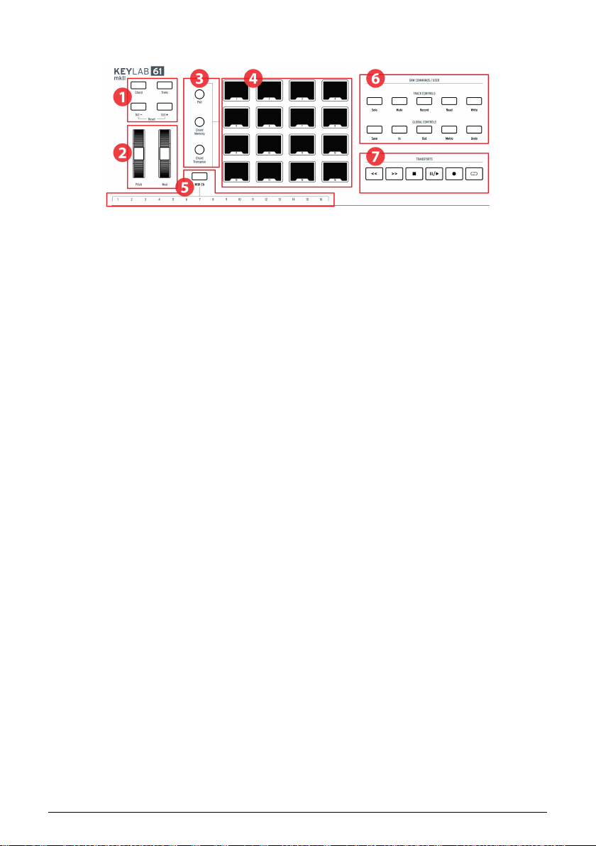
1.2. The Front Panel (left)
1. Octave, Chord & Transpose buttons These buttons activate KeyLab mkII’s
various pitch control and chord functions.
2. Pitch & Mod wheels These are used to control pitch bend and modulation
parameters of your sound.
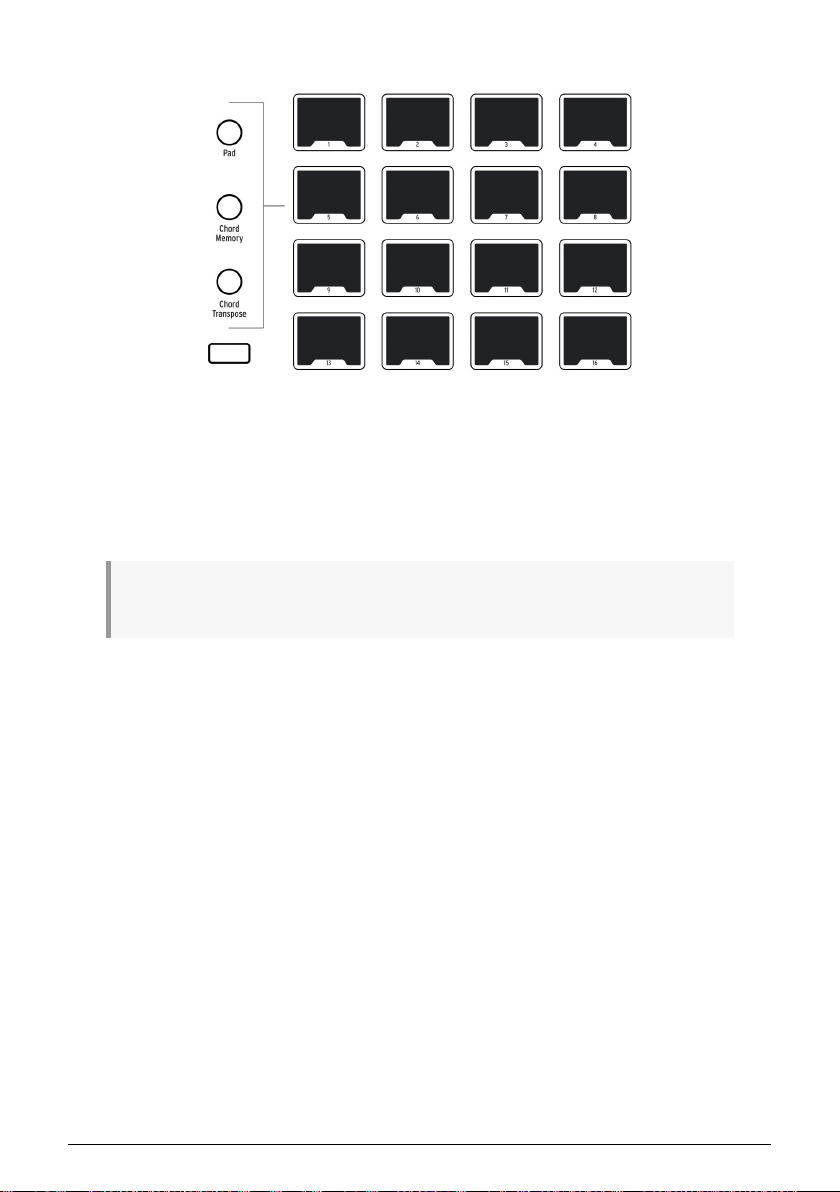
3. Pad mode buttons The three buttons to the left of the pads are used to switch
between pad modes. The Pad button selects the settings from the User preset;
the two lower buttons select different Chord modes.
4. Performance Pads The pads can be used to trigger samples within your DAW,
play chords on software/hardware instruments, and/or send all sorts of MIDI
data including polyphonic aftertouch (they're pressure-sensitive). Each pad can
have a different setting within each mode.
5. MIDI Channel selection keys Hold the MIDI Ch button and press one of the first
16 keys to select the User MIDI channel.
6. DAW Commands / User section This section controls various functions within
your preferred audio recording software, including track controls like Solo and
Mute plus other commands. If you own one of the DAWs listed here [p.33], use
the matching magnetic overlay to relabel the buttons (included).
7. Transport controls The transport section offers standard features to control your
DAW: Record, Play, Loop, etc. The transport controls are always available in all
three modes (Analog Lab, DAW, and User).
5 Arturia - User Manual KeyLab MkII - Getting Started
Page 11
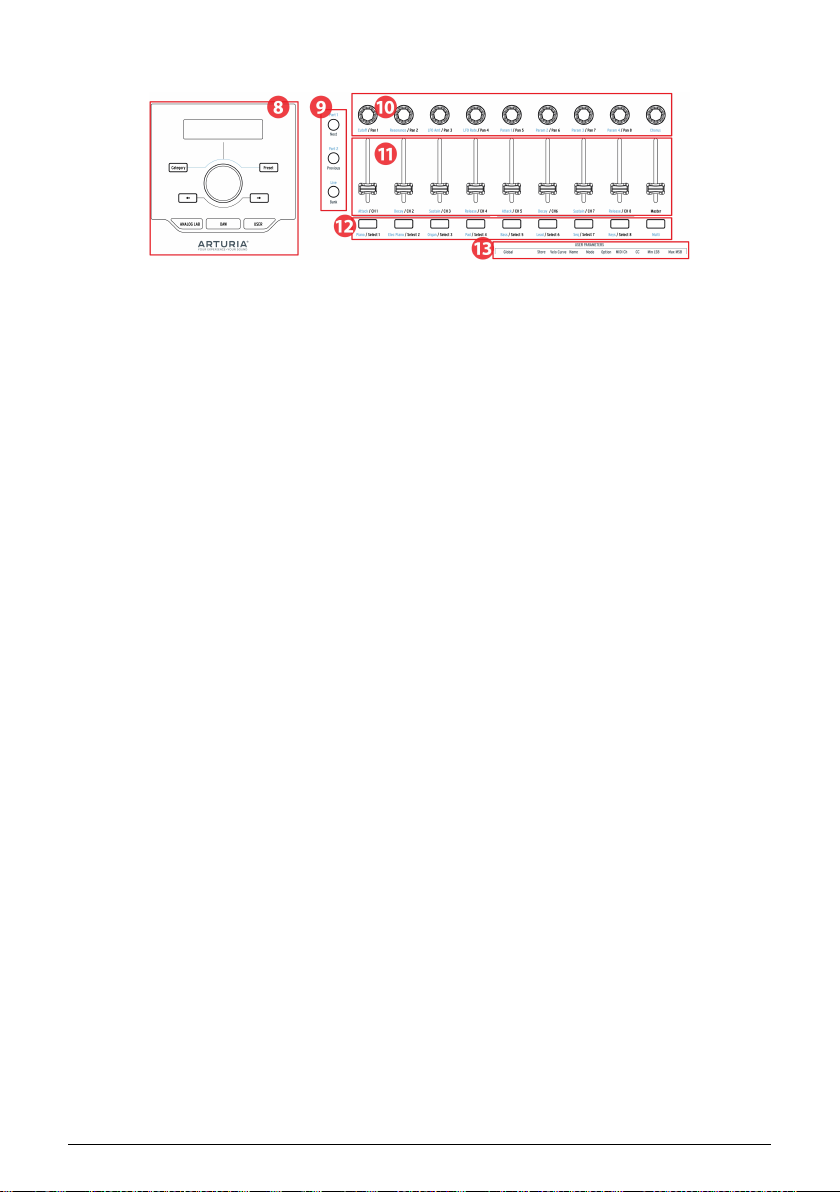
1.3. The Front Panel (right)
1. Preset Browser & Display This section is used to select presets in Analog Lab 3,
navigate menus, and display parameter and preset information.
2. Control buttons This section of 3 buttons is used in Analog Lab mode to switch
between the 2 parts in Multi Mode, select the Live tab in Analog Lab 3, and set the
split point between Parts 1 and 2. In DAW mode they're used to select the track
group in increments of 1 or 8.
3. Encoders The rotary knobs are used to control software instrument parameters,
as well as channel pan within your DAW.
4. Faders The faders are used to alter software instrument parameters, as well as
to change the volume of channels within your DAW.
5. Filter / Select buttons These buttons are used to filter preset types in Analog Lab
mode, select tracks in DAW mode, and perform user-defined functions in User
mode.
6. User Parameters The keys in the upper octave are used as shortcuts [p.48] in User
Edit mode [p.44].
Arturia - User Manual KeyLab MkII - Getting Started 6
Page 12
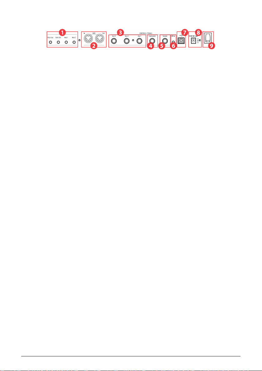
1.4. The Rear Panel
1. Pitch/Gate/Mod outputs These four connectors allow the KeyLab mkII to send
control voltages and triggers to a modular synthesis system. The voltage ranges
may be defined in User Edit mode [p.44] or by using the MIDI Control Center
[p.61].
2. MIDI In / Out KeyLab mkII's MIDI Out connector will send USB / MIDI data
to external devices, and can do so without a computer when powered with the
optional power supply. The MIDI In connector receives MIDI data from external
devices, and also serves as a MIDI / USB converter for your DAW.
3. Aux 1/2/3 Pedal Inputs These three pedal inputs can be used with a continuously
variable pedal or a footswitch. They can be assigned to any MIDI CC number
from within the KeyLab mkII [p.42] or by using the MIDI Control Center [p.61].
4. Expression Pedal Input The Expression pedal input can be used with a
continuously variable pedal or a footswitch. It sends MIDI CC# 11 by default, but
it can be reassigned from within the KeyLab mkII [p.42] or by using the MIDI
Control Center [p.61].
5. Sustain Pedal Input The Sustain pedal input automatically detects the polarity of
the pedal when KeyLab mkII is turned on, so it can be used with any standard
pedal. It also can be configured to work as a continuously variable pedal from
the front panel of the KeyLab mkII [p.42] or by using the MIDI Control Center
[p.61].
6. CV In Use this connector to route a control voltage output from a modular
synthesizer into the KeyLab mkII. This input can be used as a CV-to-MIDI
converter and/or a CV-to-USB converter. The voltage range may be defined from
the front panel or using the MIDI Control Center [p.61].
7. USB Connection Use this to connect KeyLab mkII to your computer. This port
provides both power, MIDI data, and control information.
8. Power connector If you'd like to use KeyLab mkII as a controller without a
computer attached, connect an optional 9-12v DC 1.0A power supply here.
9. Power switch This on/off switch works the same whether the unit is powered by
USB or by the AC adapter: up is on, down is off.
1.4.1. Something to consider: Ground loops
A ground loop is an unwanted current in a conductor connecting two points. The result
is noise in your audio signal, usually in the form of a low-frequency hum. In setu ps
involving computers, CV/Gate connections, and audio devices, it's possible to end up with an
annoying ground loop. We have provided a solution, however: the anti ground loop adapter.
1.4.1.1. When should I use the anti ground loop adapter?
In most cases you will not need the anti ground loop adapter.
If you don't have a ground loop problem in your setup, simply connect the KeyLab mkII
with the supplied USB cable to a computer or with an optional 9-12v DC 1.0A power supply.
7 Arturia - User Manual KeyLab MkII - Getting Started
Page 13

You should use the included anti ground loop adapter if you experience background noise in
your speakers that disappears when you disconnect the KeyLab mkII from your computer
or from the CV/Gate connections to your analog gear. A ground loop can also cause
problems with pitch tracking when using the KeyLab mkII CV connections with analog
synthesizers.
Connect the anti ground loop adapter as follows:
Arturia - User Manual KeyLab MkII - Getting Started 8
Page 14

2. OVERVIEW
2.1. Keyboard
KeyLab mkII features a synth-action keyboard that is both velocity- and pressure-sensitive.
The keys can be used as shortcuts [p.9] to access parameters in User mode. For example,
holding the MIDI Ch button and tapping one of the lowest 16 keys will select the User MIDI
channel (see below).
2.1.1. Changing the MIDI Channel
The MIDI channel of the KeyLab mkII can be changed by holding the MIDI Ch button and
pressing one of the first 16 keys on the keyboard. After this all controls that have been set to
follow the User MIDI Channel will change to that channel.
For example, to change KeyLab mkII’s MIDI output to channel 8, hold the MIDI CH button
and hit the lowest G on the keyboard.
2.1.2. The keyboard shortcuts
Certain keys on the keyboard can be used with front-panel buttons to provide shortcuts
to settings such as the User MIDI Channel, Global settings, and various User Edit mode
parameters. For a complete listing of these features, click here [p.48].
9 Arturia - User Manual KeyLab MkII - Overview
Page 15

2.2. Pitch and modulation wheels
These controllers allow for real-time pitch bend and modulation control.
Moving the Pitch Wheel up or down will raise or lower the pitch of the selected sound. The
range of this effect is set within the hardware or software instrument being controlled.
Moving the Modulation Wheel u p increases the modulation amount of the selected sound.
The response depends on the settings of the instrument being controlled. The Modulation
Wheel is assigned to MIDI CC# 1 by default, but it can be reassigned from the front panel
[p.42] or using the MIDI Control Center [p.61].
♪: The Pitch Wheel cannot be reassigned to send another type of MIDI data.
Arturia - User Manual KeyLab MkII - Overview 10
Page 16
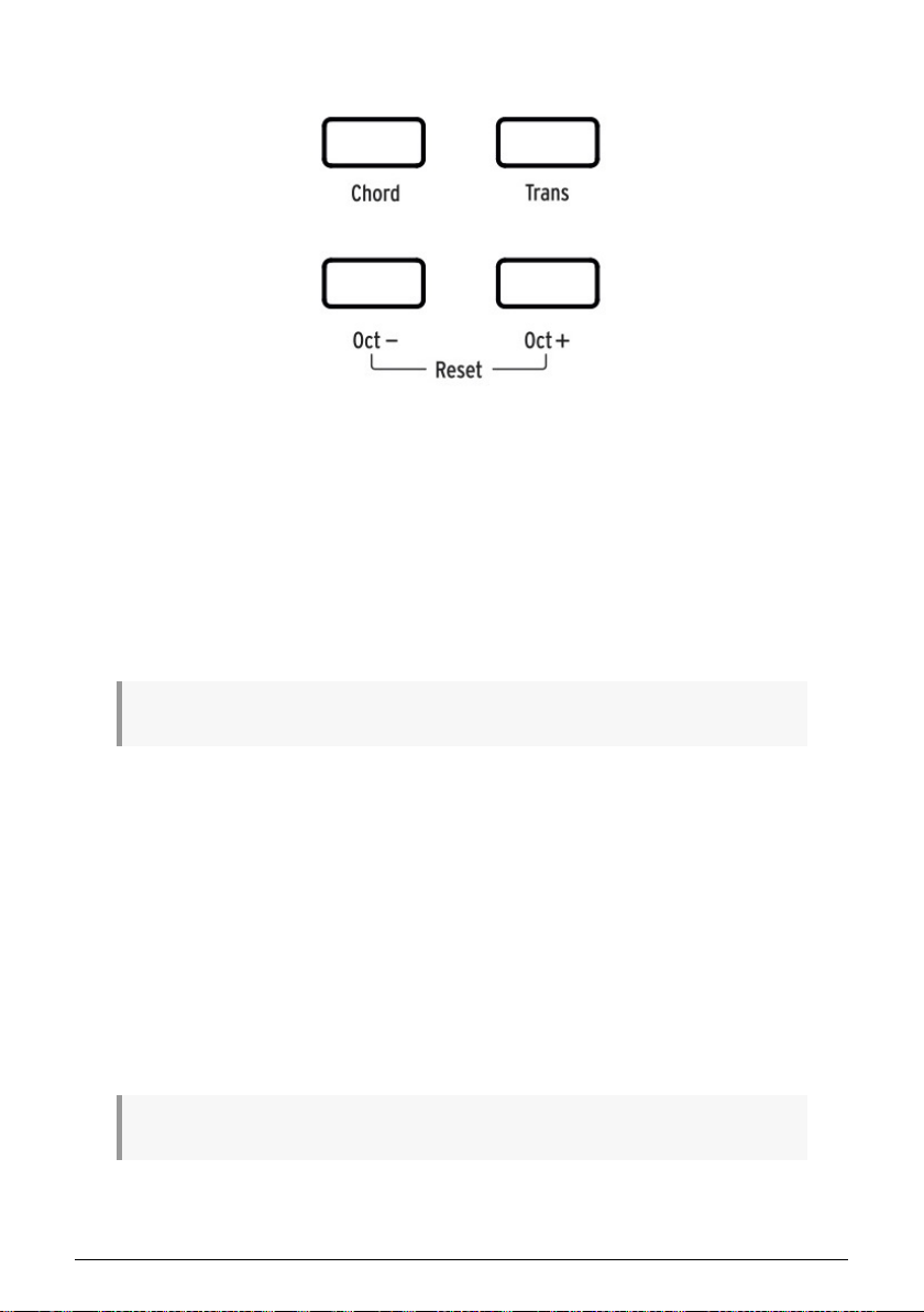
2.3. Octave control and Transpose
2.3.1. Setting the Octave
Pressing the Oct - and/or Oct + buttons will shift the range of KeyLab mkII’s keyboard,
giving you access to higher and lower pitches.
When activated, the selected octave button will blink at a certain speed to indicate how low
or high you have transposed the keyboard. It will blink faster as the keyboard is transposed
further away from center.
To quickly reset the octave shift and return the KeyLab mkII to the center pitch range
position, press the Oct - / Oct + buttons simultaneously.
♪: The Octave and Transpose settings are saved with the User map presets.
2.3.2. Activating Transpose
The Transpose function lets you shift the pitch of the keyboard chromatically to make it
easier to perform in different keys.
To transpose the KeyLab mkII hold the Trans button and select the root note of the new key.
Notes lower than middle C will transpose down, and notes above middle C will transpose
up. Press any C key while holding the Trans button to cancel the transposition.
When the Trans button is lit brightly the KeyLab mkII is transposed. When it is not lit the
KeyLab mkII is not transposed.
The transposition feature can be toggled on and off. When the Trans button is dimly lit that
means the keyboard is not currently transposed, but that there is a transposition amount
being held in memory. Pressing the Trans button again will re-transpose the keyboard.
♪: The range of the Transpose function is -11 to +11 notes. Use the Octave buttons to extend this range.
11 Arturia - User Manual KeyLab MkII - Overview
Page 17

2.3.3. Resetting Transpose
To reset transpose mode, simply hold the Trans button down and select a C note. The light
will then turn off.
2.4. Chord button
The Chord button is used to toggle Chord mode on and off for the keyboard. If a chord has
been stored on this button, you will be able to play that chord with a single key. Playing
different keys will transpose the chord up and down. To learn how to create chords and
store them into memory, read the Chord mode chapter [p.53].
To learn about the pads and Chord mode, read the next section.
Arturia - User Manual KeyLab MkII - Overview 12
Page 18
2.5. Pad mode buttons & Pads
KeyLab mkII features 16 multi-function RGB pads that are velocity- and pressure-sensitive.
They will transmit polyphonic aftertouch, which is a highly expressive method of control for
your music.
Pads are often used to perform drum and percussion parts, but the KeyLab mkII pads can
also be used to trigger chords, send MIDI CC data, and select programs internally or on
external MIDI devices. Each pad can have its own settings, which can be edited within the
User preset [p.42] or by using the MIDI Control Center [p.61].
♪: Chord-related pad functions are covered in the Chord mode chapter [p.53]. The rest are covered in
the User mode chapter [p.42] and the MIDI Control Center chapter [p.61].
2.5.1. Three Pad modes
The three buttons to the left of the pads change what the pads do:
• Pad mode: Touch a pad and it can play a note or send a MIDI message of some
sort. The response can be defined from the front panel [p.42] or by using the MIDI
Control Center [p.61].
• Chord memory mode: Each pad stores a chord that can be played from that pad.
• Chord Transpose mode: Each pad stores a chord that can be played from the
keyboard. The Chord button must be lit to use Chord Transpose mode.
To learn how to work with the chord-related functions of the pads, refer to the Chord mode
chapter [p.53].
13 Arturia - User Manual KeyLab MkII - Overview
Page 19
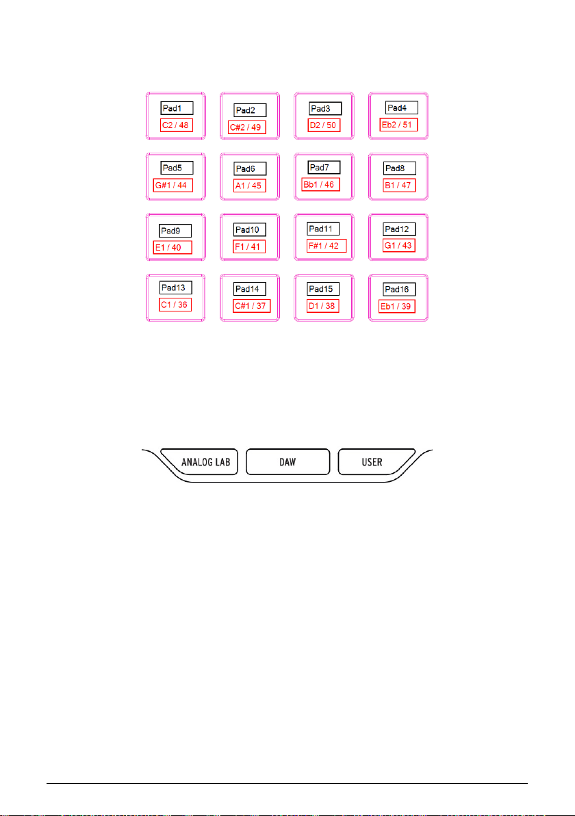
2.5.2. Pad MIDI note assignments
The default note assignments of the 16 pads are shown below:
This places the pads in a commonly-used MIDI drum mapping, with the kick drum, a snare,
the hi-hats, and the cymbals, etc., all in positions that are comfortable for playing live.
They can be reassigned to any note numbers you prefer in User Edit mode [p.44] or by
customizing the pads [p.64] in the MIDI Control Center [p.61].
2.6. Analog Lab/DAW/User modes
Three large buttons below the center knob allow you to switch the KeyLab mkII between its
three major modes:
• Analog Lab: Configures the knobs and faders to control parameters in Analog
Lab 3, as indicated by the blue text beneath each control. The center knob, the
buttons around it, and the buttons under the faders are used to filter and select
presets.
• DAW: Changes most of the KeyLab mkII front panel into a control center for your
recording software.
• User: Use the center knob to select one of 10 presets, each with its own settings
for every control. These presets may be customized from the front panel [p.42] or
by using the MIDI Control Center [p.61].
Arturia - User Manual KeyLab MkII - Overview 14
Page 20
2.7. DAW Commands section
KeyLab mkII front panel. Use the appropriate magnetic overlay for your
DAW.
When the DAW mode button is pressed the functionality of the front panel changes in many
ways. KeyLab mkII has been designed to enhance the creative process, whether you're
writing music or recording a band in your studio.
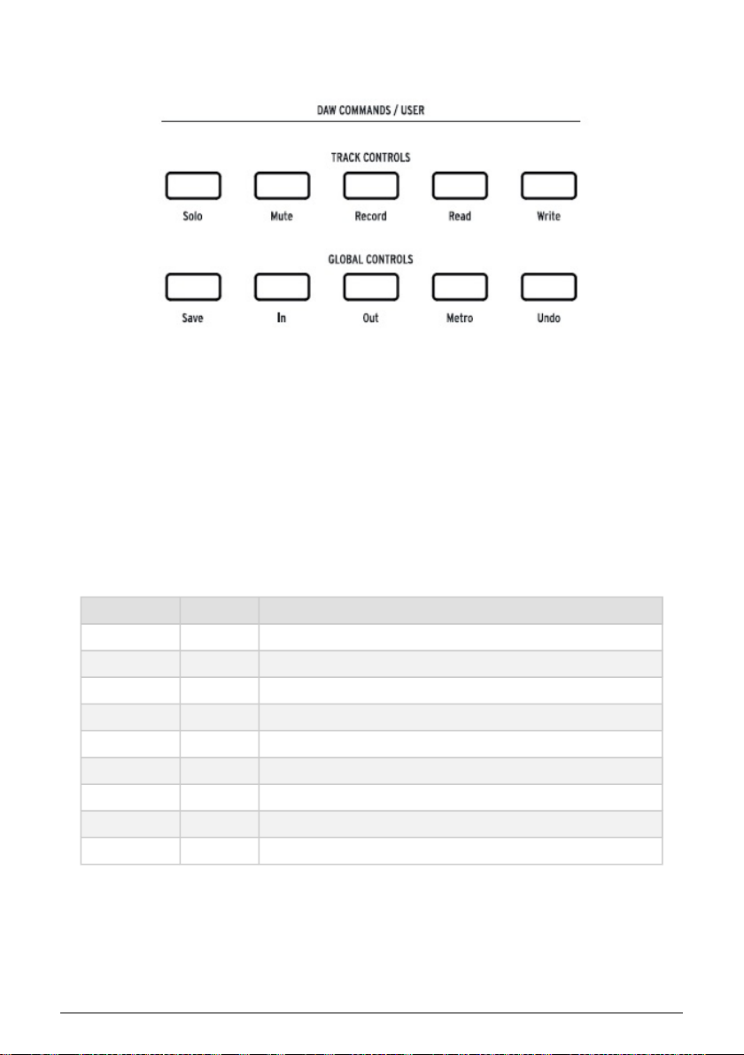
2.7.1. Track controls / Global controls
Using the industry-standard Mackie HUI data language, KeyLab mkII gives you direct
access to the most frequently used commands in your recording software, including:
Section Button Purpose
Track Controls Solo / Mute Allows the current track to be featured or muted
Record Arms the current track for recording
Read Plays back all automation that exists on the track
Write Enables recording of control automation data for the current track
Global Controls Save Saves the project
In / Out Defines the start and end ranges for “punch in” style recording
[1] Metro Toggles the DAW metronome on and off
[1] Project Opens project selection window
Undo Reverses the last action, such as a bad recording or the deletion of a track.
[1] For the Pro Tools preset this becomes a Project button, not a Metronome button.
15 Arturia - User Manual KeyLab MkII - Overview
Page 21
2.7.2. 8 DAW presets
DAW mode has 8 presets, 6 of which are preconfigured for use with popular DAW software.
We have supplied a magnetic overlay with button labels that match the functions of the
Track / Global buttons for these 6 DAWs [p.33].
There are also two generic presets for use with other DAWs (Standard MCU and Standard
HUI). The Track / Global button labels printed on the KeyLab mkII front panel match their
MCU /HUI functionality.
To select a preset, hold the DAW mode button for 1 second. Then use the center knob to
select the desired DAW configuration.
For additional information about DAW mode functionality, please refer to the DAW mode
chapter [p.32].
♪: If your DAW isn't in the preset list [p.33], it is probably compatible with either the MCU or HUI
preset. Please refer to the user guide for your DAW to see which of the two protocols is best to use.
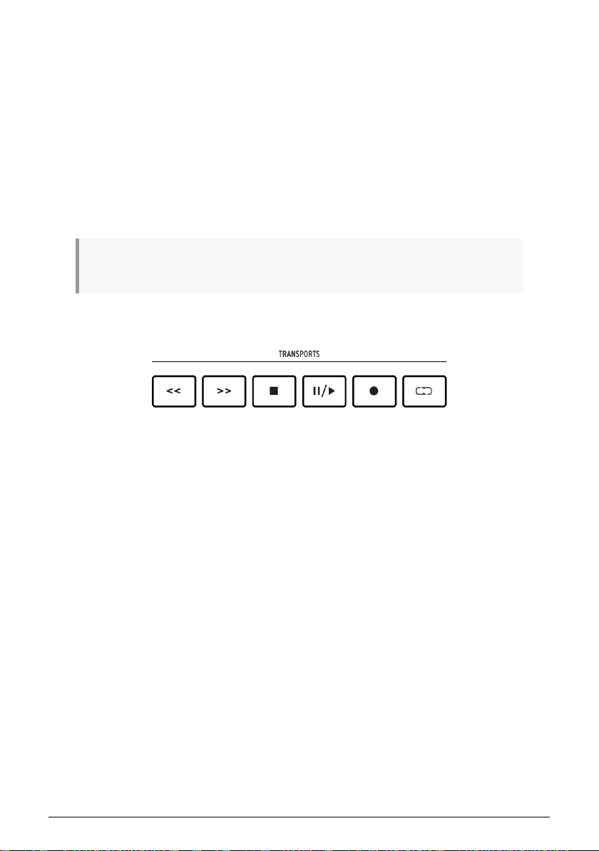
2.8. Transport controls
The Transport section puts popular transport controls at your fingertips: Rewind, Fast
forward, Stop, Play / Pause, Record, and Loop.
Arturia - User Manual KeyLab MkII - Overview 16
Page 22
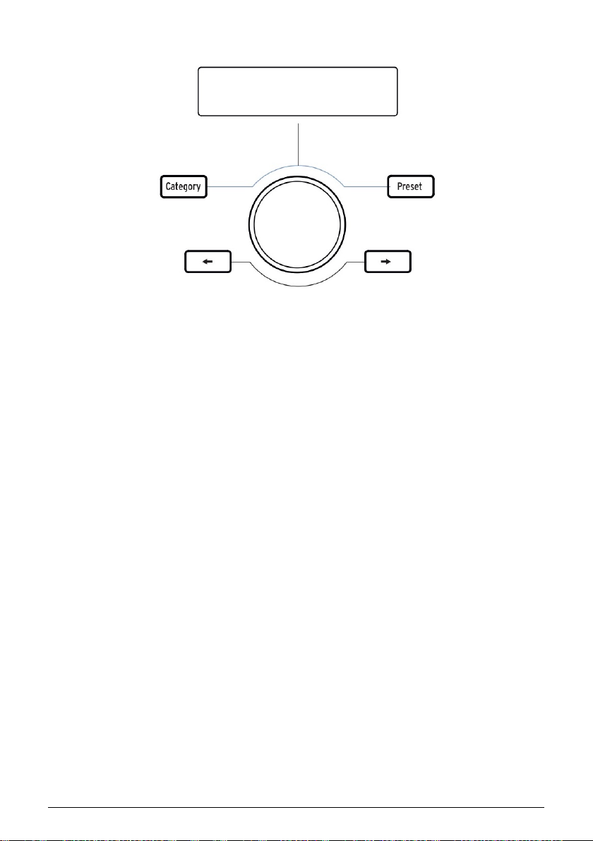
2.9. Preset Browser & Display
KeyLab mkII features a powerful Preset Browser and clickable center knob to help you
quickly find the sound you’re looking for within Analog Lab 3.
The Category, Preset, and Left / Right arrow buttons are used to select presets in Analog
Lab mode [p.23], so all four buttons are lit in this mode.
However, in User Edit mode [p.44] only the Left / Right arrow buttons are used for item
selection, so they are lit but the Category/Preset buttons are not.
To place KeyLab mkII into Analog Lab mode, press the Analog Lab button under the center
knob. For more information about Analog Lab mode, please refer to the Analog Lab 3
manual or the Analog Lab chapter [p.23] in this manual.
To place KeyLab mkII into User mode, press the User button under the center knob. For learn
about User mode, please read the User mode chapter [p.42].
17 Arturia - User Manual KeyLab MkII - Overview
Page 23
2.10. Control buttons
The Control buttons are used to switch the functions of KeyLab mkII’s encoders, faders, and
buttons. Their purposes depend on the selected mode:
• Analog Lab mode [p.23]: Select one of three layers of definable controller
assignments and Macros within a Multi. Also, the Live button is used to activate
Split mode [p.30] and set the split point.
• DAW mode [p.32]: Select different groups of tracks
• User mode [p.42]: choose one of three banks of definable controller assignments
Please refer to the appropriate sections of this manual via the links above to learn more
about each mode.
2.11. Encoders
The 9 rotary knobs of KeyLab mkII are endless encoders with dual functionality.
In Analog Lab mode [p.23] the encoders will affect the corresponding parameters displayed
within Analog Lab 3. The first four encoders have the names of the parameters they control
listed in blue text, as does the ninth encoder (Chorus). The functions of encoders 5-8 may be
different from one preset to the next.
In DAW mode [p.32] the encoders will alter the panning of their corresponding track on the
mixer.
Each of the 10 User presets [p.42] allow the encoders to transmit various types of MIDI
control data. Three banks of settings are available for each of the 9 encoders. It is also
possible to name each of the encoders, and the display will show that name when the
encoder is turned. These choices can be made from the front panel [p.42] or by using the
MIDI Control Center [p.61].
Arturia - User Manual KeyLab MkII - Overview 18
Page 24

2.12. Faders
Like the encoders, KeyLab mkII’s 9 faders have multiple functions that vary depending on
the selected mode.
In Analog Lab mode [p.23] faders 1-8 control the envelope parameters indicated in the blue
text under the faders. Fader 9 is reserved for the master volume of the preset.
In DAW mode [p.32] faders 1-8 control the volume of 8 channels within your DAW, and fader
9 controls the master volume. Different sets and banks of tracks may be selected using the
three control buttons immediately to the left of the faders.
The faders can also send several types of MIDI data, with three banks of settings available
within each of the 10 User presets [p.42]. These can be assigned from the front panel [p.42]
or by using the MIDI Control Center [p.61]. It is also possible to name each of the faders, and
the display will show that name when the fader is moved.
2.13. Filter/Select buttons
Each of the 9 buttons beneath the faders serves a different role depending on which mode
has been selected.
In Analog Lab mode [p.23] the buttons are used to select a certain type of instrument (Piano,
Lead, etc.). Once the options have been narrowed in this way it is even faster to find the
right preset.
In DAW mode [p.32] the buttons are used to select one of the tracks within your DAW.
Different sets and banks of tracks may be selected using the three buttons immediately to
the left of the faders.
In User mode [p.42] the buttons can send MIDI control data, MIDI notes, or program
changes, with three banks of settings available within each of the 10 presets [p.42]. These
can be assigned from the front panel [p.42] or by using the MIDI Control Center [p.61].
♪: Each button can be assigned its own color, but this can only be done using the MIDI Control Center
[p.61].
19 Arturia - User Manual KeyLab MkII - Overview
Page 25
2.14. Rear panel connections
♪: The rear panel was introduced in the Getting Started chapter [p.4], and the capabilities of the pedals
and the CV/Gate/Mod section will be covered in chapter 5 [p.42] and chapter 7 [p.58], respectively. Only
brief summaries will be given here.
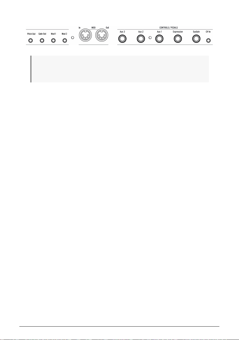
2.14.1. Controls/Pedals/CV In
Each of the five pedal inputs can be configured to send various types of MIDI data. Their
labels indicate their default assignments, but any one of the in puts can work with either a
foot switch or an expression pedal. The function of each pedal can be edited from the front
panel [p.42] or by using the MIDI Control Center [p.61].
The CV In connection allows a control voltage from an external device to be used as a
modulation source in User mode. From there its input values can be captured by your DAW.
For more information, see the User mode chapter [p.42] and the CV/Gate/Mod connections
chapter [p.58].
2.14.2. Pitch/Gate/Mod Outputs
These four connectors enable the KeyLab mkII to interface with a modular synthesis
system. The voltage ranges may be defined in User Edit mode [p.44] or by using the MIDI
Control Center [p.61].
Arturia - User Manual KeyLab MkII - Overview 20
Page 26
2.15. Additional features
2.15.1. Global settings
The KeyLab mkII has some very useful keyboard shortcuts. We've already covered how to
change the MIDI Channel [p.9], and all of the others are described in the User mode chapter
[p.48].
But the Global parameters determine the behavior of the KeyLab mkII in all modes and all
presets, so it's best to mention them here.
2.15.1.1. Access to Global settings
Here's how to view or edit the Global parameters:
1. Press and hold the User mode button for 1 second. It will begin to flash.
2. Press the top D key. The display will read "Global" in the top row and "LowPower"
in the bottom row.
3. Turn the center knob to view the Global parameter you want to edit
4. Click the center knob to select the parameter
5. Turn the center knob to change the value of that parameter.
These settings can also be edited using the MIDI Control Center [p.61], which provides access
to other functions such as pedal calibration [p.80].
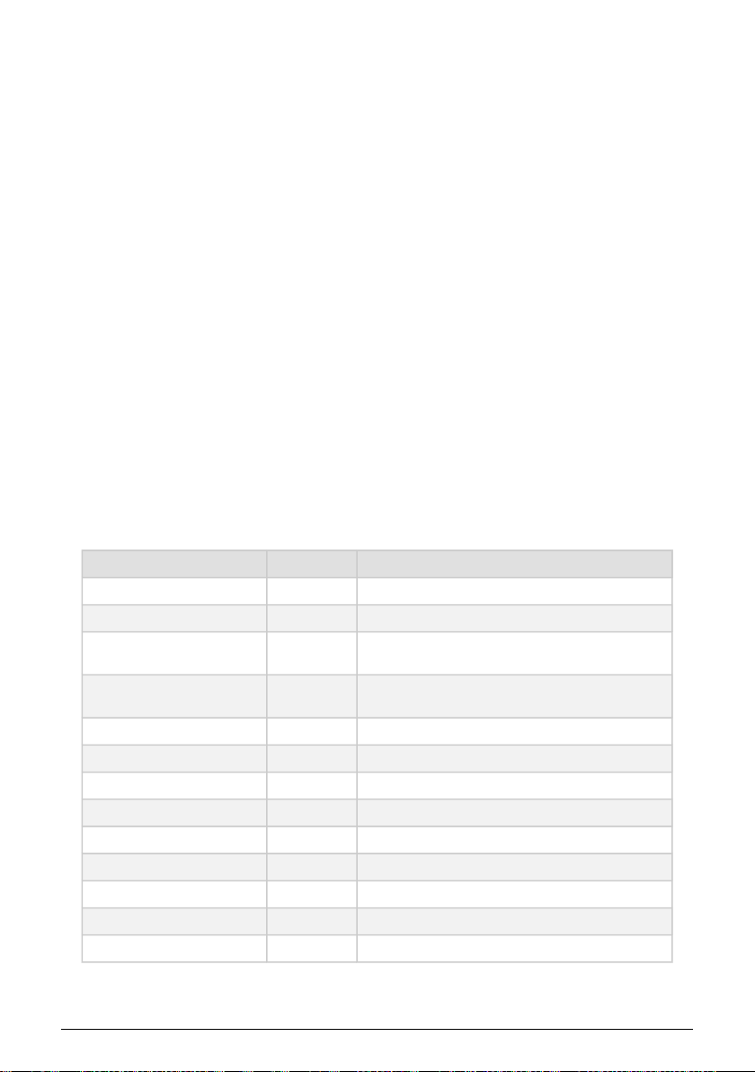
2.15.1.2. Global settings chart
Name Range Description
Low Power mode On/Off Enable/disable power-up & Vegas mode light shows
Vegas mode On/Off Toggle the "time-out" light show feature
DAW Fader mode
User Fader mode
Pad Velocity curve Lin/Log/Exp Select pad velocity response preference
Pad Aftertouch curve Lin/Log/Exp Select pad aftertouch response preference
Pad Aftertouch minimum 0-127 Set minimum range for pad aftertouch
Pad Aftertouch maximum 0-127 Set maximum range for pad aftertouch
Keyboard Aftertouch curve Lin/Log/Exp Select keyboard aftertouch response preference
Keyboard Aftertouch minimum 0-127 Set minimum range for keyboard aftertouch
Keyboard Aftertouch maximum 0-127 Set maximum range for keyboard aftertouch
MIDI In to USB On/Off Choose whether to pass incoming MIDI data to USB host
USB In to MIDI Out On/Off Choose whether to pass USB host data to MIDI Output
Jump/
Pickup
Jump/
Pickup
Set Fader response preference
Set Fader response preference
21 Arturia - User Manual KeyLab MkII - Overview
Page 27

2.15.2. Sending a Panic Message
It's possible a note might continue playing if you switch between different instruments while
holding down a key. Similarly, sometimes a controller value will remain at an unwanted
value. These situations can be fixed easily by sending what is known as a "Panic Message",
which resets all controllers and sends a "note off" message to all MIDI channels.
To send a Panic message from the KeyLab mkII, press the Stop button quickly three times.
2.15.3. Factory Reset
Sometimes you may wish to reset your KeyLab mkII back to the factory settings. This
process will initialize the unit, putting in its default state.
!: Performing a factory reset will overwrite all 10 User presets with a default preset. Be sure to back
up your settings using the MIDI Control Center.
To perform a factory reset on your KeyLab mkII, follow these simple steps:
• Turn off the KeyLab mkII using the power switch on the back of the unit.
• Press and hold Oct+ and Oct- buttons.
• Turn the power switch back on.
• The LCD screen will display a factory reset message.
• To confirm that you want to perform the factory reset, press the center knob.
Arturia - User Manual KeyLab MkII - Overview 22
Page 28

3. ANALOG LAB MODE
KeyLab mkII has been designed to shine in many musical environments, and it is perfectly
suited for the included Analog Lab 3 software. From helping you select the perfect sound to
allowing complete control over that sound, KeyLab mkII and Analog Lab 3 are a powerful
combination.
♪: The focus of this chapter will be the features of KeyLab mkII, with occasional explanations of
Analog Lab 3 for your convenience. For in-depth information about Analog Lab 3, please consult the
manual for that software.
3.1. Connecting to Analog Lab
Before you can enjoy the close integration of KeyLab mkII and Analog Lab 3, there are
some initial conditions that must be met:
• Analog Lab 3 needs to be downloaded, installed, and activated as described here
[p.3]
• Connect KeyLab mkII to your computer
• Launch the Analog Lab 3 application
• Press the Analog Lab button on the KeyLab mkII (under the center knob) to enter
Analog Lab mode
• Play a note on the keyboard. If Analog Lab 3 does not respond, check its
preferences and be sure KeyLab mkII is selected in the MIDI Devices window
as shown below.
After this, every time you start Analog Lab 3 it should connect to the KeyLab mkII on its
own. But since this is the first time you may need to select it in the MIDI Controller field at
the bottom of the Analog Lab 3 window:
23 Arturia - User Manual KeyLab MkII - Analog Lab mode
Page 29

If you've met the conditions listed above, let's begin!
♪: When in DAW mode you can switch to Analog Lab mode and do everything described in this
chapter, if the instrument assigned to the current track is Analog Lab 3. The DAW Commands section
and the transport section will continue to function as they do in DAW mode. But keep in mind that the
Track select buttons will be used to filter sounds in Analog Lab 3; to select different tracks and track
groups, switch back into DAW mode.
Arturia - User Manual KeyLab MkII - Analog Lab mode 24
Page 30

3.2. Part / Live selection
There are 3 control buttons located to the left of the encoders, faders, and Filter buttons.
(They are bracketed in red in the graphic above.) In Analog Lab mode the blue text above
the control buttons reveals their purpose:
• Part 1: Select the controls for the current single instrument or for Part 1 of the
current Multi
• Part 2: Select the controls for Part 2 of the current Multi, or add a second layer
[p.30] to a single preset
• Live: Select the controls for the Macro parameters, Part volume/panning, and
Send A / B controls of the current Multi. If the Live button is held and a key is
pressed, Split mode [p.30] will be enabled.
♪: Macros are created within Analog Lab 3. To learn more about Macros and Multis, please consult
the Analog Lab 3 user manual.
25 Arturia - User Manual KeyLab MkII - Analog Lab mode
Page 31

3.3. Browsing Presets
With Analog Lab mode selected the center section and the Filter buttons work together to
streamline the process of selecting presets. There are almost 7,000 presets to audition in
Analog Lab 3, but KeyLab mkII helps you find the right sound quickly.
3.3.1. Filter buttons
The Filter/Select buttons
There are times during the creative process when you already know the type of sound you
want: an acoustic piano, a lead, or a sequence, for example. The Filter buttons might be the
place to start in this case. They're located under the faders, and each of the 9 buttons is
labeled in blue with a useful category filter:
Filter type Description
Piano Acoustic pianos: concert grand, upright, etc.
Elec Piano Electric pianos: Suitcase, Stage, Wurlitzer, etc.
Organ B3, Farfisa, Vox Continental, etc.
Pad String synthesizers, ethereal voices, pads of all sorts
Bass Classic synthesizer basses, organ pedal instruments, etc.
Lead Synthesizer lead sounds ranging from mellow to aggressive
Seq Sequences and arpeggiator patterns: monophonic or polyphonic
Keys Synths and sounds from other instruments that are good for comping, etc.
Multi Splits and layers using sounds from all categories
For example, if you press the Piano button it will engage the piano filter and load a piano
sound; press the Pad button and presets matching that description will be made available
immediately.
As soon as a filter choice is made, the name of the first matching preset will appear in the
display with an asterisk to its left. After this you can use the Left / Right arrow buttons or the
center knob to scroll through the filter results. To disengage the filter, press the same Filter
button again.
When the Multi button is pressed Analog Lab 3 will select the Multi category, where two
instruments can be played at the same time. For full details about Multi mode, please refer
to the Analog Lab 3 user guide.
Arturia - User Manual KeyLab MkII - Analog Lab mode 26
Page 32

3.3.2. Category and Preset buttons
The Category and Preset buttons let you use the center knob with Analog Lab 3 to select the
instrument, type, or style you are looking for, which will help to narrow down your search.
You can view the options in the KeyLab mkII display as well as in Analog Lab 3.
Once you have scrolled to the characteristic you want, press the center knob to select it.
Your choice will also be outlined in blue in Analog Lab 3. You can remove that characteristic
by clicking the center knob again.
When you have selected the desired characteristics, you can then press the Preset button
and use the center knob to navigate through the presets that match your selection. To
choose a preset, click the center knob.
A quicker way to audition the list of filtered presets is to use the Left / Right arrow buttons.
This will load the next preset immediately so you don't have to press the center knob first.
3.3.3. Clear all filters
To clear all of the filter characteristics quickly, scroll fully counter-clockwise to the Clear: All
Sounds page and then click the center knob. You can also use the "Clear All" button inside
Analog Lab 3.
27 Arturia - User Manual KeyLab MkII - Analog Lab mode
Page 33

3.4. Encoders and Faders
As with each mode in the KeyLab mkII, when you enter Analog Lab mode the controls to the
right of the display assume different functions. We covered the Filter buttons in the Browsing
Presets section [p.26]; now we will describe the new functions of the encoders and faders.
♪: It is possible that some presets may have different controller assignments than are listed on the
front panel.
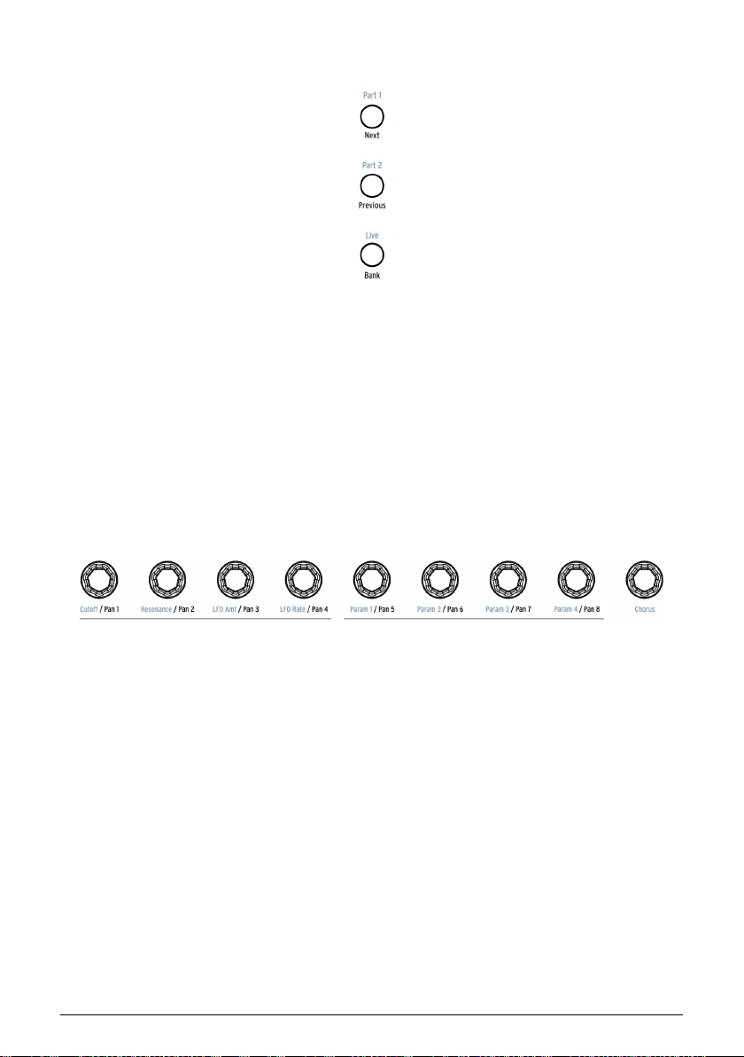
3.4.1. The Encoders
The blue text under the encoders reveals their function for Part 1 and Part 2 in Analog Lab
mode:
Encoder # Function Description
1 Cutoff Controls cutoff frequency of the filter(s)
2 Resonance Sets the resonance amount for the filter(s), when available
3 LFO Amt Determines the depth of the LFO modulation
4 LFO Rate Adjusts the speed or sample/hold time of the LFO(s)
5 Param 1 Assignable; varies per preset
6 Param 2 Assignable; varies per preset
7 Param 3 Assignable; varies per preset
8 Param 4 Assignable; varies per preset
9 Chorus Controls the chorus effect level
Arturia - User Manual KeyLab MkII - Analog Lab mode 28
Page 34

3.4.2. The Faders
The blue text under the encoders reveals their function for Part 1 and Part 2 in Analog Lab
mode:
Fader # Function Description
1 Attack Controls the attack rate of the filter envelope
2 Decay Adjusts the decay rate of the filter envelope
3 Sustain Sets the sustain level of the filter envelope
4 Release Determines the fade-out time of the filter envelope after a key is released
5 Attack Controls the attack rate of the amplitude envelope
6 Decay Adjusts the decay rate of the amplitude envelope
7 Sustain Sets the sustain level of the amplitude envelope
8 Release Determines the fade-out time of the amplitude envelope after a key is released
9 Master Controls the output volume of Analog Lab (Parts 1 and 2)
3.4.3. The Live button
The Live button selects a third bank of assignments for the encoders and faders in Analog
Lab mode. When this button is pressed the Live tab will be selected in Analog Lab 3. It allows
you to assign Macros to encoders 1-8, each of which can control up to 4 parameters drawn
from Part 1, Part 2, or both. The blue text under the faders does not identify their functions
when the Live button is pressed.
The Live tab is also where mixer-type assignments for the faders can be made. Available
parameters include Panning, Level, Effects Sends and Returns, and other parameters for
each Part.
♪: To learn more about the Live tab, please consult the Analog Lab 3 user manual.
29 Arturia - User Manual KeyLab MkII - Analog Lab mode
Page 35

3.5. Build a Multi
In Multi mode you can have two presets active on the keyboard at the same time. They can
be either layered or split, with one preset on one side of the keyboard and a second preset
on the other side.
Here's how to build a Multi from the ground up.
3.5.1. Start with a single preset
First we'll need to call up a single preset inside Analog Lab 3. Select any one of the presets,
as long as it isn't a Multi. The difference is that a single Analog Lab 3 preset will show a
picture of only one instrument on the right side of the application window, while a Multi will
display two instruments (or two pictures of the same instrument).
After you have done this only Part 1 will be active on the KeyLab mkII. When you play a
note on the keyboard you will hear only one Analog Lab 3 preset. To verify this visually, the
Part 1 button should be lit on the front panel.
Now scroll through the preset list using the center knob until you find a sound you'd like to
build into a Multi. You can use the Filter buttons [p.26] to narrow your search, of course; just
don't press the Multi button for now (that's the furthest one on the right side).
3.5.2. Add Part 2
If you're familiar with the various ways to select presets [p.26] and you'd like to start
combining them into a Multi, press the Part 2 button. Analog Lab 3 will switch to Multi mode,
place the Multi in Swap mode, and "open" the Part 2 slot in the Analog Lab 3 window.
Now you can select a preset for Part 2 from the KeyLab mkII front panel using the same
filtering techniques you used to select the first preset: Filter buttons, category selection, etc.
♪: For specific details about Multi Mode or Swap mode, please refer to the Analog Lab 3 manual.
3.5.3. Setting a split point
At first both presets will be layered, one on top of the other. If you'd like to have them on
different sides of the keyboard you'll need make them into a split Multi. This can be done
from the KeyLab mkII or using Analog Lab 3.
To set the split point using the keyboard, hold the Live button and press a key. The display
will show the name of the key you have pressed to confirm that S plit mode has been
enabled. Part 1 will go to the left side of the split point and Part 2 will be placed on the right
side of the split point. Then release the Live button and the screen will return to the previous
page.
You can use this shortcut in two ways:
• To move the split point of a Multi that is already in Split mode, or
• To turn a layered Multi into a split Multi.
Arturia - User Manual KeyLab MkII - Analog Lab mode 30
Page 36

3.5.4. Removing the split point
To remove a split point, hold the Live button and then press the split point key. The display
will show the word "Off" after pressing the split point key to confirm that S plit mode has
been disabled. If you accidentally press the wrong key, just press it again. Then release the
Live button and the screen will return to the previous page.
♪: Adding/removing a split point can also be a useful feature when building a layered Multi: S plit the
keyboard to focus on what each Part is contributing to a layer, then remove the split point to recombine
the Parts and double-check the blend, the playability, etc.
31 Arturia - User Manual KeyLab MkII - Analog Lab mode
Page 37

4. DAW MODE
Pressing the DAW mode button in the center section puts the KeyLab mkII into DAW mode.
8 DAW mode presets are available, with 6 intended for use with particular DAW applications.
There are also Standard MCU and Standard HUI presets. Between these 8 presets the
KeyLab mkII should be compatible with almost any DAW.
4.1. An overview of DAW mode
All three of the main modes exist when KeyLab mkII is in DAW mode (Analog Lab, DAW,
and User), and you may switch between them freely. Some DAW mode functions will not
be available if you switch modes, though.
For example, the Track Select buttons will change their function to match the chosen mode
on the KeyLab mkII: if you enter Analog Lab mode and open the Analog Lab 3 interface on
a track, the Track Select buttons will now serve as the Filter buttons for Analog Lab 3.
However, any DAW-specific KeyLab mkII controls not being used by Analog Lab mode will
still fulfill their DAW mode functions. For example, the DAW Commands buttons will continue
to perform the Track and Global functions of the selected DAW preset.
But as soon as you switch into User mode, the DAW Commands buttons will perform the
functions that were assigned to them in the current User Preset. They will display their DAW
mode names when pressed, but they will not transmit those commands.
And when User mode is selected it will function as expected, even while the Transport
section is used to control the DAW. For instance, you can still select User presets using the
same method described here [p.42].
♪: The Transport buttons perform the same function no matter which of the three main modes is
selected (Analog Lab, DAW, or User).
Arturia - User Manual KeyLab MkII - DAW mode 32
Page 38

4.2. DAW preset selection
Hold the DAW mode button for 1 second to enter the DAW Preset selection page. Next, turn
the center knob and scroll through the list to find the name of your DAW. Click the center
knob to select that preset, and then the features of the KeyLab mkII will be reconfigured to
match the most important functions of your DAW.
♪: If your DAW doesn't have a preset listed below, its compatibility with KeyLab mkII depends on
how the DAW handles the MCU and HUI protocols. For more information consult the KeyLab mkII page
on the Arturia website or the documentation of the DAW you are using.
4.2.1. List of DAW presets
Preset DAW
1 Standard MCU
2 Standard HUI
3 Ableton Live
4 Logic Pro X
5 Pro Tools
6 Cubase
7 Studio One
8 Reaper
33 Arturia - User Manual KeyLab MkII - DAW mode
Page 39

4.3. Track / Global controls
Using the industry standard Mackie HUI data language, KeyLab mkII gives you direct
access to the most frequently used commands in your recording software. The difference
between the Track Controls and the Global Controls is this:
• Track control buttons perform their functions only on the currently selected track
• Global control buttons affect the entire song or project. Their actions are
performed regardless of which track is selected.
The following two sections focus on the assignments that correspond to the printing on the
front panel, but a list of the assignments for each DAW preset are found here [p.38].
4.3.1. Track Controls
KeyLab mkII front panel buttons. Use the appropriate
• Solo: causes the current track to be featured
• Mute: silences the current track
• Record: arms the current track for recording
• Read: allows automation data embedded in the current track to become active
• Write: allows automation data to be written to the current track
magnetic overlay for your DAW.
4.3.2. Global Controls
Pictured: KeyLab mkII front panel buttons. Use the
appropriate magnetic overlay for your DAW.
• Save: Saves your track.
• In: Defines the start point for “punch in/out” recording
• Out: Defines the end point for “punch in/out” recording
• Metro: Toggles the DAW metronome on and off
• Undo: Reverses your last action, such as deleting a track, or capturing a MIDI
performance.
♪: The buttons in the DAW Commands section send predetermined control messages to your
software, and cannot be repurposed within DAW mode. However, they can be assigned to send various
MIDI commands in User Edit mode [p.42].
For a complete list of the Track / Global Control button assignments for each of the DAW
presets, click here [p.38].
Arturia - User Manual KeyLab MkII - DAW mode 34
Page 40

4.4. The transport controls
The Transport section puts popular transport controls at your fingertips:
• Rewind / Fast-forward: The exact response of these buttons depends on the DAW
you are using. Some might accelerate the playback cursor forward or backward;
others might jump by 1 bar, or jump to the next/previous marker, etc. But as a
general concept, the Rewind / Fast-forward buttons are a quick way to move the
playback cursor back and forth so you can find specific points in your track.
• Stop: Stops playback. In some recording software, this will also return the
playback cursor to the start of the track.
• Play / Pause: Starts and pauses your track at the current position of the playback
cursor in your DAW.
• Record: Arms the record function in your DAW. Hitting the Record button while
the track is stopped will begin playback while recording. If the track is already
playing, hitting Record will begin recording from the current playback cursor
position.
• Loop: Toggles the Loop function in your DAW on and off. The loop region is set
within your software.
♪: The Transport buttons always send commands using the MCU / HUI protocols and cannot be
reassigned in any mode.
4.5. The Center Knob: Use as Jog Wheel
When DAW mode is selected, the center knob can be used as a "jog wheel" to move the
playback cursor within your recording software backward and forward, speeding u p your
workflow.
35 Arturia - User Manual KeyLab MkII - DAW mode
Page 41

4.6. Channel/Bank selection
The control buttons are located to the left of the encoders, faders, and buttons. The black
text under these 3 buttons reveals their function in DAW mode:
• Next / Prev: Shifts the range of the selected channels in your DAW, which allows
you to focus the encoders, faders, and buttons on a particular set of channels.
The amount of shift is determined by the Bank button:
◦ Bank button ON (lit): Next / Previous buttons shift tracks by 8 channels
◦ Bank button OFF (dark): Next / Previous buttons shift tracks by 1
channel
• Bank: Toggles the function of the Next/Prev buttons.
4.7. Track selection
The black text under these buttons reveals their function in DAW mode:
• Track button 1 selects the first track in the selected bank as the target of the Track
Control buttons
• Track button 2 selects the second track in the selected bank as the target of the
Track Control buttons
• Track button 3 selects the third track in the selected bank as the target of the
Track Control buttons
…and so on. After the track has been selected, the Track Control buttons determine and
display the status of the selected track: Solo, Mute, Record enabled/disabled, Automation
Read/Write, etc.
♪: In DAW mode, Button 9 only has a function with Ableton Live: It allows you to toggle the Faders
function. The default setting will control track volume, and the other setting will control the track "SEND
A" knob.
Arturia - User Manual KeyLab MkII - DAW mode 36
Page 42

4.8. Encoders, Faders
In DAW mode the encoders and faders provide essential mixing features for the group of
eight tracks that is currently selected.
4.8.1. Encoders in DAW mode
The black text under the encoders reveals their function in DAW mode:
• Encoder 1 controls the stereo field panning position for the first track in the
selected bank
• Encoder 2 controls the stereo field panning position for the second track in the
selected bank
• Encoder 3 controls the stereo field panning position for the third track in the
selected bank
...and so on.
♪: Encoder 9 does not have a function in DAW mode.
4.8.2. Faders in DAW mode
The black text under the faders reveals their function in DAW mode:
• Fader 1 controls the level of the first track in the selected bank
• Fader 2 controls the level of the second track in the selected bank
• Fader 3 controls the level of the third track in the selected bank
...and so on through fader 8, which controls the level of the eighth track in the selected bank.
Fader 9 is different, though: it controls the Master Volume of the entire song or project.
♪: There are two response behaviors available for the faders in DAW mode: Jump or Picku p [p.79].
The choice can be made from the front panel of the KeyLab mkII [p.21] or using the MCC [p.61].
37 Arturia - User Manual KeyLab MkII - DAW mode
Page 43

4.9. DAW Preset Command chart
4.9.1. Standard MCU
Section Button Purpose
Track Controls Solo / Mute Allows the current track to be featured or muted
Record Arms the current track for recording
Read Plays back all automation that exists on the track
Write Enables recording of control automation data for the current track
Global Controls Save Saves the project
In / Out Define the start / end limits for “punch in” style recording
Metro Toggles the DAW metronome on and off
Undo Reverses the last action, such as a bad recording or the deletion of a track.
4.9.2. Standard HUI
Section Button Purpose
Track Controls Solo / Mute Allows the current track to be featured or muted
Record Arms the current track for recording
Read Plays back all automation that exists on the track
Write Enables recording of control automation data for the current track
Global Controls Save Saves the project
In / Out Define the start / end limits for “punch in” style recording
Metro Toggles the DAW metronome on and off
Undo Reverses the last action, such as a bad recording or the deletion of a track.
Arturia - User Manual KeyLab MkII - DAW mode 38
Page 44

4.9.3. Ableton Live
Section Button Purpose
Track Controls Solo / Mute Allows the current track to be featured or muted
Record Toggles the "record ready" status of the current track
Automation Arm Enables recording of control automation data for the current track
Re-Enable Re-enables automation for parameters that have been overridden
Global
Controls
View Switch between Session view and Arrangement view
Punch In /
Out
Metro Toggles the metronome on and off
Undo
Define the start / end points for “punch in” style recording
Reverses the last action, such as a bad recording or the deletion of a
track.
4.9.4. Logic Pro X
Section Button Purpose
Track Controls Solo / Mute Allows the current track to be featured or muted
Record Arms the current track for recording
Read Plays back all automation that exists on the track
Write Enables recording of control automation data for the current track
Global Controls Save Saves the project
Replace Toggles track between "Replace" and "Overdub" recording modes
Auto-Punch Enables punch in/out recording within the defined ranges
Metro Toggles the DAW metronome on and off
Undo Reverses the last action, such as a bad recording or the deletion of a track.
39 Arturia - User Manual KeyLab MkII - DAW mode
Page 45

4.9.5. Pro Tools
Section Button Purpose
Track Controls Solo / Mute Allows the current track to be featured or muted
Record Arms the current track for recording
Read Plays back all automation that exists on the track
Write Enables recording of control automation data for the current track
Global Controls Save Saves the project
Punch Enables “punch in” style recording within the defined ranges
Mix Invokes the Mix window
Proj Opens the Project selection menu
Undo Reverses the last action, such as a bad recording or the deletion of a track.
4.9.6. Cubase
Section Button Purpose
Track Controls Solo / Mute Allows the current track to be featured or muted
Record Arms the current track for recording
Read Plays back all automation that exists on the track
Write Enables recording of control automation data for the current track
Global
Controls
Save Saves the project
Punch In /
Out
Metro Toggles the DAW metronome on and off
Undo
Define the start / end points for “punch in” style recording
Reverses the last action, such as a bad recording or the deletion of a
track.
Arturia - User Manual KeyLab MkII - DAW mode 40
Page 46

4.9.7. Studio One
Section Button Purpose
Track Controls Solo / Mute Allows the current track to be featured or muted
Record Arms the current track for recording
Read Plays back all automation that exists on the track
Write Enables recording of control automation data for the current track
Global Controls Save Saves the project
Auto-Punch Enables “punch in” style recording within the defined ranges
Mixer Invokes the Mixer window
Metro Toggles the DAW metronome on and off
Undo Reverses the last action, such as a bad recording or the deletion of a track.
4.9.8. Reaper
Section Button Purpose
Track Controls Solo / Mute Allows the current track to be featured or muted
Record Arms the current track for recording
Read Plays back all automation that exists on the track
Write Enables recording of control automation data for the current track
Global
Controls
Save Saves the project
Zoom Out /
In
Metro Toggles the DAW metronome on and off
Undo
Changes the focus range of the track window
Reverses the last action, such as a bad recording or the deletion of a
track.
41 Arturia - User Manual KeyLab MkII - DAW mode
Page 47

5. USER MODE
5.1. General concepts
Press the User mode button to put KeyLab mkII into User mode. 10 User presets are
available, each with its own set of MIDI controller assignments for nearly everything on the
front and rear panels. The presets can be named for quick identification, as can all three
banks of encoders and faders.
When a control is activated from the top level of User mode the display will show which
control is being used, the type of MIDI data it is sending, its assigned MIDI channel, and the
value of the data being sent.
All of these parameters can be edited from the front panel in User Edit mode [p.44] or by
using the MIDI Control Center [p.61]. There are also keyboard shortcuts [p.48] available to
help you quickly find the parameters you want to edit.
5.2. User preset selection
Once the KeyLab mkII is in User mode, you can turn the center knob to scroll through the
10 Presets. When you find the one you want, click the center knob to select it. The KeyLab
mkII will be configured immediately with the settings that were stored with that preset.
5.3. The Display in Play mode
The top level of User mode is known as Play mode. In this mode the display provides instant
feedback about what is happening, such as octave shift, which chord is being played, and
which control has been activated.
When a control is activated there are two main types of data that will be displayed:
Play mode: Expression pedal activated
Controls such as the Expression pedal and Mod Wheel show their names and their current
value in the top row and their MIDI assignments in the bottom row.
In the case of the faders, encoders, and the Select buttons, the display contains an
additional field.
User Edit mode: Encoder 1, Bank 1 selected
For these controls the top row of the display shows which control is being used, which of
the three control banks is currently selected, and the value of the data being sent, and then
is shows the MIDI channel assignment and the data type being sent.
Arturia - User Manual KeyLab MkII - User mode 42
Page 48

5.4. Controller bank selection
The control buttons on the left side of this graphic are used to select which of the three banks
of encoders, faders, and buttons are being accessed from the front panel. The appropriate
button will be lit to indicate which bank is active.
43 Arturia - User Manual KeyLab MkII - User mode
Page 49

5.5. User Edit mode
Hold the User mode button for 1 second to enter User Edit mode. The display will then ask
you to move the item you want to edit, such as
• a fader, an encoder, or one of the Select buttons
• one of the DAW Commands / User buttons
• a pad
• a pedal
• one of the wheels
• a key on the keyboard
• a voltage received at the CV In connector
Once you have activated the item to be edited, turn the center knob and the lower line of the
display will show you which parameters are available for that control.
When you see the parameter you want to edit, click the center knob to enter the value field
and then turn the knob to change the value for that parameter. Click the knob again to jump
back to the parameter selection field.
5.5.1. Select a control for editing
There are two main ways to select another control for editing:
• Move that control, or
• Use the the Left / Right arrow buttons to select controls that are nearby.
5.5.1.1. Selecting the CV controls
In some cases you need to use a combination of the control selection procedures described
above. For example, here's how to select the following items:
• CV Mod Input: Press Select button 9, then press the right arrow once
• CV Pitch/Gate/Mod Outputs: Activate the Aux 3 pedal, then press the right arrow
once.
However you do it, once the new control has been selected simply use the center knob to
select one of its parameters. Then click the knob to edit the value for that parameter.
♪: The keys in the upper octave of the keyboard can be used in User Edit mode as shortcuts [p.48] to
different parameter groups and other functions.
All of the User Edit mode parameters are also available in the MIDI Control Center [p.61].
♪: Remember to save your edits [p.52] frequently.
Arturia - User Manual KeyLab MkII - User mode 44
Page 50

5.5.2. The Display in User Edit mode
There may be more parameter fields in the display depending on the control you have
selected for editing. In the two examples that follow, each of the red boxes in the graphic
indicates a field where a value can be changed. The control itself determines what is shown
in the top row, and the center knob is used to change the items in the bottom row.
The name of the control displayed in the top row will change when you:
• move a control to select it, or
• use the Left / Right arrows to select a nearby control.
5.5.2.1. User Edit: Sustain Pedal
User Edit mode: Sustain pedal selected
Since there is only one Sustain Pedal (or Mod Wheel, or Expression Pedal, etc.), the top row
of the display shows only the name of the control.
The bottom row of the display shows the parameter that is currently selected for editing,
such as the Mode, MIDI Channel, or Option, etc. At this point you can
• turn the center knob to select a different parameter to edit for this control (box 2)
• click the center knob to switch to the value field (box 3)
• turn the center knob to change the selection
• click the center knob to return to the parameter field and select a new parameter,
etc.
45 Arturia - User Manual KeyLab MkII - User mode
Page 51

5.5.2.2. User Edit: Faders
User Edit mode: Fader 8 selected
In the case of the Faders (or Encoders, or Select buttons) there are 9 in each bank (top row,
box 1), and there are three banks of them (top row, box 2), for a total of 27 assignable faders.
The items in the top row are changed by
• moving one of the controls to select it (box 1)
• pressing one of the Control buttons (Part 1, Part 2, Live) to select the bank (box 2).
The bottom row of the display shows the parameter that is currently selected for editing,
such as the Mode, MIDI Channel, or Option, etc. At this point you can
• turn the center knob to select a different parameter to edit for this control (box 3)
• click the center knob to switch to the value field (box 4)
• turn the center knob to change the selection
• click the center knob to return to the parameter field and select a new parameter,
etc.
♪: Control banks 1-3 are selected with the Control buttons (Part 1, Part 2, Live), not the center knob.
Arturia - User Manual KeyLab MkII - User mode 46
Page 52

5.5.3. The Keyboard
There are several ways to configure the KeyLab mkII keyboard. It will always send MIDI
note data, of course, but there are lots of additional options. You can specify whether the
keyboard will
• Operate in Split mode or not, and define the split point
• Transmit data for Part 1 or Part 2 (when split) on the User channel or another
MIDI channel
• Choose one of three velocity curves for the keyboard
• Enable channel pressure (aftertouch) for Part 1 or Part 2
• Specify whether Octave Shift / Transpose will affect Part 1 or Part 2
• Select whether Chord Mode is active for Part 1 or Part 2
5.5.3.1. User mode: Part 1 vs. Part 2
Part 1 transmits on the MIDI channel for the keyboard when split mode is not active. When
split modeisactive the keyboard is split into two virtual keyboards, Part 1 and Part 2, after
which the Parts may be assigned to different MIDI channels. In other words, Part 2 is only
available when Split mode is active.
♪: When in User Edit mode, press any key below the top octave to select the Keyboard itself as the
control to edit. The keys in the top octave are used as parameter shortcuts (see below).
5.5.3.2. Keyboard split: User mode
To set the split point using the keyboard you must be in User Edit mode. After that, here's the
process:
• Press any key lower than the top octave of the keyboard
• Turn the center knob to select the SplitMode parameter page
• Click the knob to jump to the value field
• Turn the knob to change the value to On
• Click the knob again to return to the parameter selection field
• Turn the center knob to select the SplitPoint parameter page
• Click the knob to jump to the value field
• Turn the knob to change the split point value
• Click the knob to return to the parameter selection field, or move another control
to edit something else.
• Remember to store the User preset to preserve the split point and any other
changes.
♪: In User mode, Part 1 is on the
point. This is the opposite of the Split mode part assignments [p.30] in Analog Lab mode.
47 Arturia - User Manual KeyLab MkII - User mode
right
side of the split point and Part 2 is on the
left
side of the split
Page 53

5.5.3.3. Keyboard shortcut chart
Here's a list of all of the keyboard shortcuts:
Mode Name Button/key combination Function [2]
All [1] MIDI Ch
User Edit
[3]
Global
[p.21]
Store E key in upper octave [2] Enter Store page to save User preset
Velo Curve F key in upper octave [2] Set response curve for the keyboard
Name F# key in upper octave [2] Enter names for encoders, faders
Mode G key in upper octave [2] Select control function or disable it (Off)
Option G# key in upper octave [2] Select control response (gate/toggle, etc.)
MIDI Ch Highest A key [2] Set MIDI channel for current control
CC Bb key in upper octave [2] Choose MIDI CC # or note number
Min LSB B key in upper octave [2] Set minimum range for current control
Max MSB Highest C key [2] Set maximum range for current control
[1] Analog Lab, DAW, User mode [2] Some shortcuts are not available for certain controls due
to feature differences. [3] To access these parameters, first hold the User mode button for 1
second to enter User Edit mode.
MIDI Ch + one of the 16 lowest
keys
D key in upper octave
Define the User MIDI channel
Settings for keyboard/pad/fader response,
etc.
5.5.4. The Wheels
The two wheels on the left side of the keyboard serve very different purposes.
5.5.4.1. Pitch wheel
The Pitch wheel sends MIDI Pitch Bend messages. It can't be reassigned to transmit another
type of data, but you can choose whether it will affect Part 1, Part 2, or both.
5.5.4.2. Modulation wheel
The Modulation wheel normally sends MIDI CC# 1, but it can be reassigned to a different CC
number using the MIDI Control Center [p.61]. Whatever it is configured to transmit, its data
can be sent from Part 1, Part 2, or both.
Arturia - User Manual KeyLab MkII - User mode 48
Page 54

5.5.5. The Pads
♪: If one of the two Chord Memory buttons next to the pads are selected, they will only send the
MIDI note data that has been stored with the chord for that pad.
Each of the 16 pads can be assigned to send one of the following types of data on any MIDI
channel or on the User channel:
• The MIDI note number of your choice (with velocity and polyphonic aftertouch)
• Switch between two particular values of any MIDI CC number (toggle or gate
operation)
• Send a MIDI Program change / Bank Select message
The pads can also be used to call up a different User preset than the one currently selected.
More than one pad can be set to do this, which gives you the option to go in different
directions during a live performance, for example.
♪: The MCC [p.61] can be used to specify a particular color for each pad. If you choose the color blue
to re present MIDI notes and the color green to represent Program Changes, for example, then you'll
know at a glance which pad does what, even on a darkened stage.
5.5.6. DAW Command / User buttons
The DAW Command buttons can be used as switches to send particular MIDI data when in
User mode. The commands they can send are:
• Two particular values of any MIDI CC number (toggle or gate operation)
• MIDI Program change / Bank Select messages
Each button can have its own setting. And as with every other programmable control, these
settings can be made from the front panel or by using the MIDI Control Center [p.61].
49 Arturia - User Manual KeyLab MkII - User mode
Page 55

5.5.7. Three banks of controls
It looks like there are only 27 controls in this section, but there are actually 81! That's because
there are three separate banks of controls, which are selected using the three control
buttons immediately to the left of the assignable controls.
Keep in mind that as you select the options that there are more fields in the display [p.42]
for these controls than for the others (since there are three banks for each control).
Some options are available only through the MIDI Control Center [p.61], such as the color for
the Select buttons.
5.5.7.1. Encoders
The encoders may be assigned to send one of the following types of data on any MIDI
channel or the User channel:
• MIDI CC data within a specific range
• RPN/NRPN data within a specific range
Other important features of the encoders include:
• Absolute or Relative mode transmission methods can be chosen
• Encoders can be named
• Each encoder may have its own acceleration setting, which affects how many
turns it takes to reach the minimum/maximum values. This setting can only be
set using the MIDI Control Center [p.61].
5.5.7.2. Faders
The faders may be assigned to send one of the following types of data on any MIDI channel
or the User channel:
• MIDI CC data within a specific range
• RPN/NRPN data within a specific range
Other important features of the faders include:
• Normal or Drawbar mode (inverted performance)
• Faders can be named
• They can be configured to send new values as soon as they are moved (Jump
mode) or only after the current value of the parameter has been reached (Pickup
mode). This choice can be made from the front panel of the KeyLab mkII [p.21]
or using the MCC [p.61].
Arturia - User Manual KeyLab MkII - User mode 50
Page 56

5.5.7.3. Buttons
The Select buttons may be assigned to send one of the following types of data on any MIDI
channel or the User channel:
• Two specific values of MIDI CC data
• A specific RPN/NRPN message
• MIDI Program change / Bank Select messages
You can also specify a particular color for each button using the MIDI Control Center [p.61]. If
you choose the color blue to represent MIDI CC messages and the color green to represent
Program Changes, for example, then you'll know at a glance which button does what, even
on a darkened stage.
5.5.8. Pedals / CV connectors
5.5.8.1. CV Input
♪: To learn the quickest way to select the CV connectors in User Edit mode, see Selecting the CV
controls [p.44].
This rear-panel connector can receive incoming control voltages and turn them into MIDI
data that your DAW can use. The voltage range can be defined, as can the MIDI response
within that range. For more details see the the CV/Gate chapter [p.58].
5.5.8.2. Pedals
Each of the 5 pedal inputs can be set to respond to foot switches or continuously variable
pedals. The data types that can be sent are
• Switched Control: two specific MIDI CC values (toggle or gate operation)
• Program Change: MIDI Program change / Bank Select messages
• Control: MIDI Continuous Control data within a specific range
5.5.8.3. Control Voltage Outputs
These four outputs have very specific functions. We'll cover the details in the CV/Gate
chapter [p.58], so what we'll focus on here are the general concepts:
• Pitch Out: Translates MIDI note number into a control voltage
• Gate Out: Translates MIDI note on/off messages into high/low trigger voltages
• Mod 1: Translates MIDI velocity data into a control voltage by default, but another
source may be chosen
• Mod 2: Translates Modulation Wheel values into control voltages by default, but
another source may be chosen
51 Arturia - User Manual KeyLab MkII - User mode
Page 57

5.6. Non-assignable controls
As you can see, almost every button/pad/fader/knob on the front panel can be assigned to
transmit various types of data. Here's a list of those that
• Chord / Transpose / Octave – / Octave +
• Pad / Chord mode buttons
• The three Control buttons
• Transport buttons
• Category / Preset / Left arrow / Right arrow
• Center knob
• Part 1 / Part 2 / Live (they select controller banks 1-3)
• MIDI Ch button: can only be used with the keyboard to set the User channel
♪: The Transport buttons always send commands using the MCU / HUI protocols and cannot be
reassigned in any mode.
can't
be reassigned:
5.7. Store the preset
!: Following the steps in this section will overwrite one of the 10 User presets. Make sure you've used
the MIDI Control Center to back up anything you don't want to lose.
It's a good idea to save your work frequently, so once you've worked on a few controller
assignments you should store the User preset. Since you're already in User Edit mode you
can take advantage of the keyboard shortcut to start the Store process, so press the top E
key and let's walk through it.
1. The first screen in Store mode asks you to choose one of the 10 User preset
locations.
2. Turn the center knob to select an available User preset.
3. Click the center knob and enter a new name for the preset if you like. Use the
center knob to select a character or letter, and use the Left / Right arrow buttons
to move from one character field to the next.
4. When you are done naming the preset, click the center knob and the preset will
be stored to the selected location.
5. The display will return to the top level of User mode with the new preset selected.
♪: Another way to begin the Save process from within User Edit mode is to press the User button,
after which the display will ask you if you want to save what you have done. If so, click the center knob
and follow the procedures outlined above.
Arturia - User Manual KeyLab MkII - User mode 52
Page 58

6. CHORD MODE
KeyLab mkII features an advanced Chord mode which lets you perform chords on the
keyboard or the pads using only one finger.
6.1. Overview of Chord mode
The Chord button [p.55] can record and recall a single chord, which can then be played on
the keyboard.
The Chord button chord is not preserved when the KeyLab mkII is disconnected from a
power source, but the pads [p.56] can store up to 32 Chords in two different Chord modes
(Chord Memory [p.56] and Chord Transpose [p.56]).
The three buttons immediately to the left of the pads are the Pad mode buttons. The bottom
two configure the pads to store and play chords (Chord Memory) or store and recall chords
for the keyboard to play (Chord Transpose).
6.1.1. Three ways to play chords
Here's an overview of how the Chord button, the keyboard, and the pads interact in each of
the Pad modes:
53 Arturia - User Manual KeyLab MkII - Chord mode
Page 59

• Pad mode:
• Chord memory mode:
• Chord Transpose mode:
The contents of the Chord Memory and Chord Transpose modes are stored with the User
preset. An inde pendent set of 32 chords is also available for each of the other modes
(Analog Lab and DAW). So at any moment the KeyLab mkII can provide access to a total of
96 chords!
Remember, though: the status of the Chord button and its chord are not stored with the User
preset. And loading a different User preset does not change the status of the Chord button:
it stays enabled or disabled, just as it was when the preset was loaded.
◦ The Chord button provides a single chord that can be played and
transposed from the keyboard
◦ The pads play MIDI notes, send MIDI CC data, and/or send program
changes, etc.
◦ Use of the Chord button is optional; when it is disabled the keyboard
plays normally.
◦ The Chord button chord is not preserved when the KL mkII is power-
cycled.
◦ The Chord button provides a single chord that can be played and
transposed from the keyboard
◦ The pads store and trigger up to 16 different chords
◦ Use of the Chord button is optional; when it is disabled the keyboard
plays normally.
◦ The Chord button must be enabled
◦ Use this method to build a ‘library’ of up to 16 chords by storing them
on the pads
◦ A chord can be recalled by a pad and then played and transposed
from the keyboard.
6.1.2. How Chord mode works
The lowest note of the chord you enter is considered as the root note of the chord. For
example, if G2, C3, and E3 are entered, you have constructed a C chord in the second
inversion. But when you are in Chord mode, if you play C3 on the keyboard you will hear C3,
F3, and A3. This is because you have told the KeyLab mkII to transpose the original chord
you entered upward by five chromatic steps (i.e., a musical fourth). If you want to hear the
original chord you will need to play the G2 key.
As an additional example, let's say you want to use Chord mode to play a musical fifth with
the root note on the bottom. Here's what we recommend:
• Hold the Chord button
• Play a C and the G above it
• Release the Chord button to exit Chord entry mode
• Play a C key: you'll hear a C and the next higher G
• Play an E key: you'll hear an E and the next higher B.
Arturia - User Manual KeyLab MkII - Chord mode 54
Page 60

6.2. Chord mode: the keyboard
Chord mode is toggled on and off for the keyboard by pressing the Chord button.
♪: Only one key may be played from the keyboard when the Chord button is enabled, unless the
keyboard is in Split mode [p.47]. However, when Chord Memory mode is selected for the pads and the
Chord button is disabled, the pads will play their assigned chords and the keyboard may be played
polyphonically.
6.2.1. Create a chord for the Chord button
Hold the Chord button until it flashes and then enter u p to 6 notes on the keyboard. Release
the Chord button when you are done, and after this a single note on the keyboard will play
the chord you defined. The notes in the chord will be shown in the display, and as you play
different notes on the keyboard the chord will be transposed.
♪: All of the notes in a chord will be transmitted over USB and MIDI.
This method can be used to program a chord that would require 6 fingers, for example, or
to construct an interval that is beyond your reach. Simply hold the Chord button and play
each note one after the other, up to 6 notes, until all of the notes have been entered.
♪: The chord you create on the Chord button is not retained when the KeyLab mkII is power-cycled.
However, chords can be stored to pads [p.57] using Chord Memory mode or Chord Transpose mode.
55 Arturia - User Manual KeyLab MkII - Chord mode
Page 61

6.3. The pads: two Chord modes
The Chord Memory and Chord Transpose buttons allow the pads to do very different things.
Both features are available in all three of the main modes (AL, DAW and User), and each
main mode has its own set of 32 chords available (16 for Chord Memory and 16 for Chord
Transpose).
We've included a set of preset chords in each Chord mode so you can start making music
immediately. But you can also create and store your own chords on the pads.
The creation and storage procedures are the same for each Chord mode, so we'll cover
them both in the sections that follow. The results are very different, though. For a
comparison of all three Chord modes, read the section Three ways to play chords [p.53]
earlier in this chapter.
6.3.1. Pad Chord modes: Many uses
6.3.1.1. Chord Memory feature
The most obvious use of the Chord Memory feature is to play chords on the pads. You can
use both hands to do this, for example, or you can trigger chords with your left hand and
play a melody on the keyboard with your right hand.
A chord doesn't have to contain three or more notes, either. You can record two notes an
octave apart and trigger some fat bass notes from the pads.
6.3.1.2. Chord Transpose feature
The Chord Transpose feature is similar to the Chord Memory feature in that it allows you
to create and store 16 chords on the pads. But in this case the pads are used to recall
chords for the keyboard to play. Remember, the Chord button must be enabled for the Chord
Transpose feature to work.
With those things in mind, there are some great applications for the Chord Transpose
feature. You can:
• Build simple chords or complex ones (up to 6 notes)
• Utilize the harmonic series to try different combinations of overtones for
interesting lead sounds
• Enter the notes of several Barre chords on different pads and trigger a variety of
power chords with one key.
However you choose to use the Chord Transpose feature, you can then recall these chords
with your left hand and play them monophonically with your right hand.
Arturia - User Manual KeyLab MkII - Chord mode 56
Page 62

6.3.2. Building a pad chord
The following procedures work the same way in all of the main modes (User, Analog Lab,
DAW) whether you are in Chord Memory mode or Chord Transpose mode:
1. Enter the mode (the pads flash differently for each mode)
2. Press and hold the Chord button (next to the Trans button)
3. Select a pad:
• in Chord Memory mode the selected pad turns green; the others flash
• in Chord Transpose mode the selected pad turns lavender; the others are dark
Once the chord has been recorded, each mode offers a different way to play the chord
back.
• In Chord Memory mode the pad will play the chord recorded in step 3. It does
• In Chord Transpose mode the pad used in step 3 will select a chord for the
♪: In either mode, when a chord is triggered using a different key than the lowest one used to build
the chord, the display will show the transposed note names, not the original note names.
1. The previously-stored chord will be auditioned for reference
2. Play a chord on the keyboard, either all notes at once or one note at
a time
3. Release the Chord button
4. The pad will flash to indicate that the chord has been recorded
5. You can repeat steps 2-7 on any pad to store multiple chords.
not matter if the Chord button is on or off.
keyboard to play. The Chord button must be enabled (lit) to activate Chord
Transpose mode.
6.3.3. More about Chord Transpose mode
Chord Transpose mode is very different from Chord Memory mode, so it may be helpful to
keep these concepts in mind:
• To activate Chord Transpose mode the Chord button must be enabled.
• Select the pad from step 3 above and play the middle C key on the keyboard.
The chord you recorded will play from that key with no transposition.
• Play the middle D key and the chord will be transposed upward a whole ste p,
etc.
• If you record a different chord on another pad, you can switch back and forth
between the chords by selecting the pads, even if you keep playing the same
key repeatedly.
For example: Record a C7 chord on pad 1 and a Cm7 chord on pad 2. To change which chord
is played by middle C, press the desired pad.
57 Arturia - User Manual KeyLab MkII - Chord mode
Page 63

7. CV / GATE / MOD CONNECTIONS
Rather than merely focus on controlling DAWs, plug-in software, and MIDI devices, the
engineers at Arturia thought it would be really cool if the KeyLab mkII could also interface
with modular analog synthesizers and their components.
And so on the rear panel we included a handful of control voltage connections, giving the
KeyLab mkII the ability to interface with almost any kind of music-making technology.
Incoming voltages can be converted to USB/MIDI data and captured by your DAW, where it
can be used as a modulation source for plug-in synthesizers such as those found in Analog
Lab 3.
And in the opposite direction, the front panel controls and pedals can be routed through the
output connectors to the inputs of a modular synthesizer system.
7.1. CV Input connector
The CV input connector allows an incoming voltage to be used as a modulation source. In
User Edit mode the converted voltage can be routed to a specific MIDI CC#, on a particular
MIDI Channel, within a defined range, as if it were another control such as an Aux Pedal,
for example.
The converted signal will be sent to the MIDI and USB ports, where it can be used as a
modulation source for external MIDI devices or a software plug-in, etc.
The incoming voltage would most likely be received from a semi-modular analog
synthesizer such as Arturia's MatrixBrute, a MiniBrute 2, or some other synthesizer. There
some great modulation sources available in Eurorack format, and the CV In connector
enables you to grab the signal coming from one (or more) of those modules and use that
complex signal within a DAW environment.
Different manufacturers use different voltage standards, and so the KeyLab mkII and the
MIDI Control Center [p.61] (MCC) allow you to set the voltage range to match the incoming
device. The range is 1-10 Volts, which is broad enough to cover any analog synthesizers you
might encounter.
7.1.1. Parameters (User Edit mode)
Connector / User Edit mode name Parameter Range
CV In / CV Mod In MIDI Ch 1-16, User, Part 1, Part 2
CC 0-127
Max/MSB 0-127
Min/LSB 0-127
Volt range 1-10 V
Arturia - User Manual KeyLab MkII - CV / Gate / Mod connections 58
Page 64

7.2. Pitch/Gate/Mod connectors
The Pitch/Gate/Mod output connectors convert data from the KeyLab mkII into voltages,
which can then be used to trigger notes and control parameters on an external device such
as a modular analog synthesizer.
Each of the four connectors in the output section has a different purpose. Each one can be
edited In User Edit mode, where you can choose the options listed below in the charts [p.60].
7.2.1. Pitch Out
The normal use of a control voltage from this connector is to control the pitch on the target
device. The output voltage is based on the MIDI note number that corresponds to the key
being played. This output is monophonic, so the note priority must be specified: Low note,
High note, or the Last note played.
7.2.2. Gate Out
This sends trigger events that are generated by the note on / note off activity on the
keyboard. It is closely related to the Pitch Out connector, and will obey the note priority
setting you have chosen.
Several options are available; see the documentation for your device to learn what sort of
trigger it expects to see.
7.2.3. Mod 1
This is also a control voltage output, and its standard usage is to control a VCA (Voltage
Controlled Amplifier). By default its voltage is determined by the velocity of the key being
played on the KeyLab mkII, but it is possible to select a different source for this output in
User Edit mode [p.44] or using the MCC [p.61]. For example, a fader or an encoder could be
the source of this modulation. The maximum voltage range can be specified also.
7.2.4. Mod 2
This is also a control voltage output, and its standard usage is to control the frequency of a
VCF (Voltage Controlled Filter). By default its voltage is determined by the Mod Wheel, but it
is possible to select a different source for this output in User Edit mode [p.44] or using the the
MCC [p.61]. For example, a fader or an encoder could be the source of this modulation. The
maximum voltage range can be specified also.
59 Arturia - User Manual KeyLab MkII - CV / Gate / Mod connections
Page 65

7.2.5. Parameters (in User Edit mode)
7.2.5.1. CV Pitch
Connector / User Edit mode name Parameter Range
Pitch Out / CV Pitch Mode Volt/Oct, Hz/Volt
BaseNote 0V [a] Full MIDI note range (default = C-2)
BaseNote 1V [a] Full MIDI note range (default = C 0)
Note Priority Low / High / Last
Bend range 1-24 semitones
Assign Part 1, Part 2
[a] These two settings are mutually exclusive
7.2.5.2. CV Gate
Connector / User Edit mode name Parameter Range
Gate Out / CV Gate Mode S-Trig, V-Trig (5V, 12V)
7.2.5.3. CV Mod Out 1
Connector / User Edit mode name Parameter Range
Mod 1 / CV Mod Out 1 Assign Any control (default: Velocity)
Volt range 1-10 V
7.2.5.4. CV Mod Out 2
Connector / User Edit mode name Parameter Range
Mod 2 / CV Mod Out 2 Assign Any control (default: Mod Wheel)
Volt range 1-10 V
Arturia - User Manual KeyLab MkII - CV / Gate / Mod connections 60
Page 66

8. MIDI CONTROL CENTER
KeyLab mkII has been designed to provide quick access to the controls you use most
frequently. And though editing from the front panel is quick and easy, the MIDI Control
Center (MCC) makes this process even faster. When the KeyLab mkII is connected to
your computer, you may prefer to use the MCC to design your presets to match whatever
software or instruments you might use.
8.1. Connecting to MIDI Control Center
Once you have downloaded the MCC and installed it, simply open the program while your
KeyLab mkII is connected to your computer.
MCC will automatically connect to your device and display its image in the main window.
♪: If you have multiple Arturia devices connected to your system, you can specify which one you
will be editing by selecting it from the drop-down menu in the Device section of the MCC.
Now that your KeyLab mkII is connected and selected, let’s go over a few of the simple
ways to personalize your controller.
8.1.1. Device Memories
The Device Memories section of the MCC displays the 10 Memories that correspond to the 10
User presets within KeyLab mkII, as well as two Read-Only Memories dedicated to Analog
Lab and DAW modes.
• Analog Lab - This Memory is dedicated to using KeyLab mkII within Analog Lab
3. It is read-only, which means it cannot be altered.
• DAW - This Memory is dedicated to using KeyLab mkII to control your recording
software. It is read-only, which means it cannot be altered.
• User 1-10 - These Memories correspond to User presets 1 - 10 inside the KeyLab
mkII, and can be customized to match your setup.
• Store to - This function lets you save your current template to the highlighted
User slot in the KeyLab mkII.
• Recall from - This function lets you recall the highlighted User preset from the
KeyLab mkII, when enables you to edit and refine the settings. The revised
Memory can be saved on your computer and stored directly into one of the
KeyLab mkII User presets.
61 Arturia - User Manual KeyLab MkII - MIDI Control Center
Page 67

8.1.2. Local Templates
The Local Templates section lets you store and organize your custom User presets without
needing to save or recall settings from KeyLab mkII. It also can be used to load preconfigured control maps generated by the Arturia user community.
• Factory templates - This section displays the default settings of KeyLab mkII,
giving you a useful ‘initialized’ patch to start from or return to.
• User templates - This section displays the User presets you have recalled from
the KeyLab mkII into your computer. These can also be templates created by
other users that have been imported into the MCC.
• Save - Save the changes you have made to the current User template.
• Save As - Save a copy of the current User template and give it a new name.
• New - Creates a new, default User template.
• Delete - Deletes the User template currently highlighted.
• Import - Lets you import a pre-made User template by opening a browser.
Simply locate the desired file and hit Open.
• Export - Lets you export your User template to the location of your choice. Just
choose the location and name the file.
8.2. MCC Controller Map
The upper left corner of the MCC window has a tab labeled ControllerMap. This is the section
that allows you to customize the way the pads, encoders, faders, keyboard, and pedal
inputs react, as well as the settings for the CV Input and Output connectors. These settings
can then be stored to one of KeyLab mkII’s 10 User presets.
To select a parameter to change, simply click the graphic of the front-panel control or rearpanel connector you would like to change.
♪: Some KeyLab mkII controls cannot be customized, such as those in the Transport section.
In the next part of the manual, we’ll take a look at the options available for each of the
controls. We'll describe the fields from top to bottom and left to right.
Arturia - User Manual KeyLab MkII - MIDI Control Center 62
Page 68

8.3. Customize the Wheels
♪: Settings of
that Part 2 is available from the keyboard.
Part 2
and
Both
are only recommended when Split mode is active. That is the only time
8.3.1. Pitch Bend
The Pitch Bend wheel is reserved for that function; it can't be assigned to send any other
type of MIDI data. But you can select whether it will affect Part 1, Part 2, or both.
8.3.2. Modulation
• Mode: Select "Control" to view the rest of the parameters. Select "Off" and the
Modulation wheel will be disabled for both Part 1 and Part 2.
• Channel: Specify whether the Modulation wheel will affect Part 1, Part 2, or both.
• CC Number: The Modulation wheel sends MIDI CC# 1 by default, but it can be
configured to transmit any MIDI CC#.
• Min Value: Click/drag the knob or enter a value in the field below to set the
minimum value the Modulation wheel will send.
• Max Value: Click/drag the knob or enter a value in the field below to set the
maximum value the Modulation wheel will send.
8.4. Select the User Channel
There's a small, rectangular button between the wheels and the pads that is labeled MIDI
Ch. Click the graphic and you will be able to specify the User MIDI channel for the KeyLab
mkII.
♪: The MIDI Channel number selected for the MIDI Ch button will also change the MIDI Channel for
any control that has its MIDI Channel set to "User".
63 Arturia - User Manual KeyLab MkII - MIDI Control Center
Page 69

8.5. Customize the Pads
The Mode menu lets you choose one of the available modes for each pad independently.
Each mode contains a unique set of parameters:
8.5.1. Pad Off
Disables the pad. This can be used to prevent accidentally triggering the pad when it is not
needed in the User preset.
8.5.2. Pad MIDI Note
This option is used to output standard MIDI notes using the pad.
• Color: Select the color the pad will illuminate when played or toggled on.
• Option: Choose between Gate and Toggle. Gate activates the pad only when
played and deactivates it when released, and Toggle activates the pad when it is
pressed, and deactivates it when it is pressed again.
• Channel: Select the MIDI channel output for the selected pad, between 1 and 16.
This can also be set to “User”, which will make the pad output to the MIDI channel
selected for the MIDI Ch button [p.63].
• Note: Select the MIDI note the pad will output when played, from C-2 to G8.
The default note assignments of the 16 pads are shown here [p.14].
8.5.3. Pad Switched Control
Select this option to use the selected pad to toggle between two MIDI CC# values.
• Color: Select the color the pad will illuminate when pressed or toggled on.
• Option: Choose between Gate and Toggle. Gate activates the pad only when
pressed and deactivates it when released; Toggle activates the pad when it is
pressed and deactivates it when pressed again.
• Channel: Select the MIDI channel output for the selected pad, between 1 and 16.
This can also be set to “User”, which will make the pad output to the MIDI channel
selected for the MIDI Ch button [p.63].
• CC Number: The selected pad can be set to transmit any MIDI CC# between
0-127. Many MIDI CC numbers are named within the drop-down menu to identify
standard uses.
• Off Value: When the pad is released it doesn't have to return to a zero value.
Click/drag the knob or enter a value in the field below to set the minimum value
the pad will send when it is released.
• On Value: Click/drag the knob or enter a value in the field below to set the
maximum value the pad will send when it is pressed.
Arturia - User Manual KeyLab MkII - MIDI Control Center 64
Page 70

8.5.4. Pad Program Change
This option allows you to use KeyLab mkII’s pads to trigger program changes within virtual
instruments, outboard synths, and much more.
• Color: Select the color the pad will illuminate when it is pressed or toggled on.
• Channel: Select the MIDI channel output for the selected pad, between 1 to 16.
This can also be set to “User”, which will make the pad output to the MIDI channel
selected for the MIDI Ch button [p.63].
• Program Number: Select the MIDI Program number the pad will send when
activated. Click/drag the knob or enter a value between 0 and 127 in the field
below.
• Bank LSB: Defines the Bank Select value for Least Significant Byte (MIDI CC#
32) that the pad will send when activated. Click/drag the knob or enter a value
between 0 and 127 in the field below. Not all devices respond to Bank LSB, so
consult the documentation of the hardware or software instrument you want to
control.
• Bank MSB: Defines the Bank Select value for Most Significant Byte (MIDI CC#
0) that the pad will send when activated. Click/drag the knob or enter a value
between 0 and 127 in the field below. Not all devices respond to Bank MSB, so
consult the documentation of the hardware or software instrument you want to
control.
8.5.5. Pad Preset Change
This option lets you use any of KeyLab mkII’s pads to select a different User preset within
the KeyLab mkII.
• Color: Select the color the pad will illuminate when it is pressed.
• User preset: Choose one of the User presets between 1 and 10.
65 Arturia - User Manual KeyLab MkII - MIDI Control Center
Page 71

8.6. Customize the User buttons
The User buttons are found in the DAW Controls / User section of the front panel. These
buttons are dedicated to their DAW functions in DAW mode and Analog Lab mode, but are
assignable when in User mode. They still display their DAW mode names in User mode, but
they will send certain types of MIDI data instead.
The Mode menu lets you choose between the 3 modes available for each User button. Each
mode contains a unique set of parameters:
8.6.1. User button Off
Disables the User button. This can be used to prevent accidentally pressing the button when
it is not needed in the User preset.
8.6.2. User button Switched Control
• Option: Choose between Gate and Toggle. Gate activates the button only when
pressed and deactivates it when released; Toggle activates the button when it is
pressed and deactivates it when pressed again.
• Channel: Select the MIDI channel output for the selected button, between 1 and
16. This can also be set to “User”, which will make the button output to the MIDI
channel selected for the MIDI Ch button [p.63].
• CC Number: The selected button can be set to transmit any MIDI CC# between
0-127. Many MIDI CC numbers are named within the drop-down menu to identify
standard uses.
• Off Value: When the button is released it doesn't have to return to a zero value.
Click/drag the knob or enter a value in the field below to set the minimum value
the button will send when it is released.
• On Value: Click/drag the knob or enter a value in the field below to set the
maximum value the button will send when it is pressed.
8.6.3. User button Program Change
• Channel: Select the MIDI channel output for the selected button, between 1 to 16.
This can also be set to “User”, which will make the button output to the MIDI
channel selected for the MIDI Ch button [p.63].
• Program Number: Select the MIDI Program number the button will send when
activated. Click/drag the knob or enter a value between 0 and 127 in the field
below.
• Bank LSB: Defines the Bank Select value for Least Significant Byte (MIDI CC# 32)
that the button will send when activated. Click/drag the knob or enter a value
between 0 and 127 in the field below. Not all devices respond to Bank LSB, so
consult the documentation of the hardware or software instrument you want to
control.
• Bank MSB: Defines the Bank Select value for Most Significant Byte (MIDI CC# 0)
that the button will send when activated. Click/drag the knob or enter a value
between 0 and 127 in the field below. Not all devices respond to Bank MSB, so
consult the documentation of the hardware or software instrument you want to
control.
Arturia - User Manual KeyLab MkII - MIDI Control Center 66
Page 72

8.7. Customize the Encoders
There are 3 separate banks of encoders, which are selected using the Bank tabs.
Encoder Bank 2 selected
The Mode menu lets you choose between the 3 modes available for each encoder. Each
mode contains a unique set of parameters:
8.7.1. Encoder Off
Disables the encoder. This can be used to prevent accidentally moving the knob when it is
not needed in the User preset.
67 Arturia - User Manual KeyLab MkII - MIDI Control Center
Page 73

8.7.2. Encoder Control
• Name: Lets you enter a custom name for the encoder, which will be shown on the
display when the knob is used. The name can be a maximum of 12 characters
long.
• Option: This lets you change the encoders' response from Absolute to Relative
#1-3 [p.68].
• Acceleration: This parameter alters how the rotary encoder responds to the
speed with which you turn it. This can be set as:
◦
None:
The encoders move at a set speed and do not accelerate.
◦
Medium:
◦
Fast:
◦
1:1:
rotary knob.
• Channel: Select the MIDI channel output for the selected encoder, between 1 to
16. This can also be set to “User”, which will make the encoder output to the MIDI
channel selected for the MIDI Ch button [p.63].
• CC Number: The selected encoder can be set to transmit any MIDI CC# between
0-127. Many MIDI CC numbers are named within the drop-down menu to identify
standard uses.
• Min Value & Max Value: These parameters let you set the minimum and
maximum range of the selected encoder. Click and drag the knobs or enter a
value in the fields below them to set the range.
♪: Setting the Min & Max Values of the encoders is a great way of ensuring you only ever move within
the preferred range of a synth parameter, such as its output level, for example.
The encoders will accelerate when moved faster.
The encoders will accelerate quickly when moved faster.
The encoders will precisely match the speed that you turn the
8.7.2.1. Relative control
The "Relative" control options send only a few values to indicate direction and speed as the
encoder is turned.
To be specific, a “relative” setting sends values 61-63 when turned in a negative direction
and values 65-67 when turned in a positive direction. The turn speed determines which
value is sent. Refer to the documentation of the target instrument to see if it can respond
appropriately to these commands.
When configured this way, movements of the encoder will cause the target parameter
to change by starting at its current setting, rather than being an “absolute” control and
snapping it to some other value as soon as you start to move it.
This can be a great feature when controlling parameters like volume, filter, or effect controls,
since you may not want them to jump noticeably from their current setting when they are
modified.
Arturia - User Manual KeyLab MkII - MIDI Control Center 68
Page 74

8.7.3. Encoder RPN / NRPN
The encoders have the option to transmit Registered Parameter Numbers (RPN) or NonRegistered Parameter Numbers (NRPN). These are numbers that can be used by various
manufacturers to allow their proprietary parameters to be controlled by external devices.
Refer to the documentation of the target instrument to see if it can respond appropriately to
these commands.
• Option: Specify whether the encoder needs to transmit RPN or NRPN data.
• Channel: Select the MIDI channel output for the selected encoder, between 1 to
16. This can also be set to “User”, which will make the encoder output the RPN/
NRPN data to the MIDI channel selected for the MIDI Ch button [p.63].
• RPN / NRPN LSB: Defines the RPN/NRPN value for Least Significant Byte that the
encoder will send when activated. Click/drag the knob or enter a value between
0 and 127 in the field below.
• RPN / NRPN MSB: Defines the RPN/NRPN value for Most Significant Byte that the
encoder will send when activated. Click/drag the knob or enter a value between
0 and 127 in the field below.
69 Arturia - User Manual KeyLab MkII - MIDI Control Center
Page 75

8.8. Customize the Faders
There are 3 separate banks of faders, which are selected using the Bank tabs:
Fader Bank 2 selected
The Mode menu lets you choose between the 3 modes available for each fader. Each mode
contains a unique set of parameters:
8.8.1. Fader Off
Disables the fader. This can be used to prevent accidentally moving the fader when it is not
needed in the User preset.
8.8.2. Fader Control
This is the default mode for the fader, and it lets you customize how each fader responds
when used.
• Name: Lets you enter a custom name for the fader, which will be shown on the
display when the fader is used. The name can be a maximum of 12 characters
long.
• Option: This lets you set the fader’s function between a traditional Fader, and a
Drawbar for use with virtual organ instruments.
• Channel: Select the MIDI channel output for the selected fader, between 1 to 16.
This can also be set to “User”, which will make the fader output to the MIDI
channel selected for the MIDI Ch button [p.63].
• CC Number: The selected fader can be set to transmit any MIDI CC# between
0-127. Many MIDI CC numbers are named within the drop-down menu to identify
standard uses.
• Min Value & Max Value: These parameters let you set the minimum and
maximum range of the selected fader. Click and drag the knobs or enter a value
in the fields below them to set the range.
Arturia - User Manual KeyLab MkII - MIDI Control Center 70
Page 76

8.8.3. Fader RPN / NRPN
The faders have the option to transmit Registered Parameter Numbers (RPN) or NonRegistered Parameter Numbers (NRPN). These are numbers that can be used by various
manufacturers to allow their proprietary parameters to be controlled by external devices.
Refer to the documentation of the target instrument to see if it can respond appropriately to
these commands.
• Option: Specify whether the fader needs to transmit RPN or NRPN data.
• Channel: Select the MIDI channel output for the selected fader, between 1 to 16.
This can also be set to “User”, which will make the fader output the RPN/NRPN
data to the MIDI channel selected for the MIDI Ch button [p.63].
• RPN / NRPN LSB: Defines the RPN/NRPN value for Least Significant Byte that the
fader will send when activated. Click/drag the knob or enter a value between 0
and 127 in the field below.
• RPN / NRPN MSB: Defines the RPN/NRPN value for Most Significant Byte that the
fader will send when activated. Click/drag the knob or enter a value between 0
and 127 in the field below.
71 Arturia - User Manual KeyLab MkII - MIDI Control Center
Page 77

8.9. Customize the Select buttons
There are 3 separate banks of Select buttons, which are selected using the Bank tabs:
Select button Bank 2 is active
The Mode menu lets you choose between the 4 modes available for each Select button. Each
mode contains a unique set of parameters:
8.9.1. Select button Off
Disables the Select button. This can be used to prevent accidentally pressing the button
when it is not needed in the User preset.
8.9.2. Select button Switched Control
• Option: Choose between Gate and Toggle. Gate activates the button only when
pressed and deactivates it when released; Toggle activates the button when it is
pressed and deactivates it when pressed again.
• Channel: Select the MIDI channel output for the selected button, between 1 and
16. This can also be set to “User”, which will make the button output to the MIDI
channel selected for the MIDI Ch button [p.63].
• CC Number: The selected button can be set to transmit any MIDI CC# between
0-127. Many MIDI CC numbers are named within the drop-down menu to identify
standard uses.
• Off Value: When the button is released it doesn't have to return to a zero value.
Click/drag the knob or enter a value in the field below to set the minimum value
the button will send when it is released.
• On Value: Click/drag the knob or enter a value in the field below to set the
maximum value the button will send when it is pressed.
8.9.3. Select button RPN / NRPN
The Select buttons have the option to transmit Registered Parameter Numbers (RPN) or NonRegistered Parameter Numbers (NRPN). These are numbers that can be used by various
manufacturers to allow their proprietary parameters to be controlled by external devices.
Refer to the documentation of the target instrument to see if it can respond appropriately to
these commands.
• Option: Specify whether the button needs to transmit RPN or NRPN data.
• Channel: Select the MIDI channel output for the selected button, between 1 to 16.
This can also be set to “User”, which will make the button output the RPN/NRPN
data to the MIDI channel selected for the MIDI Ch button [p.63].
• RPN / NRPN LSB: Defines the RPN/NRPN value for Least Significant Byte that the
button will send when activated. Click/drag the knob or enter a value between 0
and 127 in the field below.
• RPN / NRPN MSB: Defines the RPN/NRPN value for Most Significant Byte that the
button will send when activated. Click/drag the knob or enter a value between 0
and 127 in the field below.
Arturia - User Manual KeyLab MkII - MIDI Control Center 72
Page 78

8.9.4. Select button Program Change
• Channel: Select the MIDI channel output for the selected button, between 1 to 16.
This can also be set to “User”, which will make the button output to the MIDI
channel selected for the MIDI Ch button [p.63].
• Program Number: Select the MIDI Program number the button will send when
activated. Click/drag the knob or enter a value between 0 and 127 in the field
below.
• Bank LSB: Defines the Bank Select value for Least Significant Byte (MIDI CC# 32)
that the button will send when activated. Click/drag the knob or enter a value
between 0 and 127 in the field below. Not all devices respond to Bank LSB, so
consult the documentation of the hardware or software instrument you want to
control.
• Bank MSB: Defines the Bank Select value for Most Significant Byte (MIDI CC# 0)
that the button will send when activated. Click/drag the knob or enter a value
between 0 and 127 in the field below. Not all devices respond to Bank MSB, so
consult the documentation of the hardware or software instrument you want to
control.
73 Arturia - User Manual KeyLab MkII - MIDI Control Center
Page 79

8.10. Customize the Keyboard
KeyLab mkII's keyboard can also be modified using the MIDI Control Center.
♪: Settings related to Part 2 and the S plit Point are only shown when S plit mode is set to On. Also,
any parameters that are set to
On.
• Part 1 Channel: Select the output MIDI channel for Part 1, between 1 and 16. This
can also be set to “User”, which will make Part 1 output to the MIDI channel
selected for the MIDI Ch button [p.63].
• Part 1 Semi: This parameter is used to set the chromatic transposition amount
for Part 1. This can be set in semitones, from -11 to +11.
• Part 1 Octave: This parameter is used to set the octave shift amount for Part 1.
The range is -3 to +3 octaves.
• Velocity Curve: Three settings are available: Linear (Lin), Logarithmic (Log), or
Exponential (Exp). This setting applies to both Part 1 and Part 2.
• Split Mode: When set to Off, Part 1 is the only active Part and the rest of the
parameters in this list are hidden. When set to On, Part 2 becomes active and
the rest of the parameters in this list are revealed. Part 1 is on the right side of the
split; Part 2 is on the left side of the split.
• Split Point: Allows you to set the split point between Part 1 and Part 2.
• Part 2 Channel: Select the output MIDI channel for Part 2, between 1 and 16. This
can also be set to “User”, which will make Part 2 output to the MIDI channel
selected for the MIDI Ch button [p.63].
• Part 2 Semi: This parameter is used to set the chromatic transposition amount
for Part 2. This can be set in semitones, from -11 to +11.
• Part 2 Octave: This parameter is used to set the octave shift amount for Part 2.
The range is -3 to +3 octaves.
• Oct buttons assign: Specify whether the Octave buttons will shift Part 1 or Part 2.
• Trans button assign: Specify whether Part 1 or Part 2 can be transposed.
• Chord button assign: Choose whether Part 1 or Part 2 will play the chord stored
on the Chord button. This also affects which half of the keyboard will work with
the pads when they are in Chord Transpose mode.
• Aftertouch assign: Select whether aftertouch is active for Part 1 or Part 2.
Part 2orBoth
will be ignored from the KeyLab mkII unless Split mode =
♪: The keyboard aftertouch curve can be specified on the Device Settings tab. It is a Global
parameter, which means it is not stored as part of the Template.
Arturia - User Manual KeyLab MkII - MIDI Control Center 74
Page 80

8.11. Customize the CV Modulation Input
The CV In connector on the rear panel can be customized from the front panel or the MCC.
Here are the available options:
8.11.1. Mod CV max voltage
Available ranges are between 1 and 10 Volts. Different manufacturers use different voltage
standards, so please refer to the documentation for your device to know which maximum
voltage range you should select.
8.11.2. Mod CV Mode menu
The Mode menu lets you choose between the 2 modes available for the pedal inputs. Each
mode contains a unique set of parameters:
8.11.2.1. Mod CV Off
Disables the CV In connector. This can be used to prevent accidentally changing your sound
when the Mod CV input is not needed in the User preset.
8.11.2.2. Mod CV Control
• Channel: Set the MIDI transmission channel for the Mod CV input, between 1 to
16. This can also be set to “User”, which will make the Mod CV input transmit to
the MIDI channel selected for the MIDI Ch button [p.63].
• CC Number: The Mod CV input can be set to transmit any MIDI CC# between
0-127. Many MIDI CC numbers are named within the drop-down menu to identify
standard uses.
• Min Value & Max Value: These parameters let you set the minimum and
maximum range of the Mod CV input. Click and drag the knobs or enter a value
in the fields below them to set the range.
75 Arturia - User Manual KeyLab MkII - MIDI Control Center
Page 81

8.12. Customize the Pedals
♪: All 5 pedal inputs have the same parameters, so we'll cover them all in this section.
The Mode menu lets you choose between the 4 modes available for the pedal inputs. Each
mode contains a unique set of parameters:
8.12.1. Pedal Off
Disables the selected pedal. This can be used to prevent accidentally changing your sound
when the selected pedal is not needed in the User preset.
8.12.2. Pedal Control
This mode lets you customize how each pedal responds when used.
• Channel: Select the MIDI channel output for the selected pedal, between 1 to 16.
This can also be set to “User”, which will make the pedal output to the MIDI
channel selected for the MIDI Ch button [p.63].
• CC Number: The selected pedal can be set to transmit any MIDI CC# between
0-127. Many MIDI CC numbers are named within the drop-down menu to identify
standard uses.
• Min Value & Max Value: These parameters let you set the minimum and
maximum range of the selected pedal. Click and drag the knobs or enter a value
in the fields below them to set the range.
♪: The Continuous Pedal Calibration [p.80] parameter in the Device Settings section [p.79] allows you
to calibrate the physical response range for each pedal when its Mode is set to Control.
Arturia - User Manual KeyLab MkII - MIDI Control Center 76
Page 82

8.12.3. Pedal Switched Control
This option can be selected to use your pedal as a binary switch.
• Option: Choose between Gate and Toggle. Gate activates the pedal only when
pressed and deactivates it when released; Toggle activates the pedal when
pressed and deactivates it when it is pressed again.
• Channel: Select the MIDI channel output for the selected pedal, between 1 to 16.
This can also be set to “User”, which will make the pedal output to the MIDI
channel selected for the MIDI Ch button [p.63].
• CC Number: The selected pedal can be set to transmit any MIDI CC# between
0-127. Many MIDI CC numbers are named within the drop-down menu to identify
standard uses. For example, to use one of the pedals as a sustain pedal, set this
value to CC# 64.
• Off Value: When the pedal is released it doesn't have to return to a zero value,
although a zero value may be needed for some external devices or software
plug-ins to function properly. Click/drag the knob or enter a value in the field
below to set the minimum value the pedal will send when it is released.
• On Value: Click/drag the knob or enter a value in the field below to set the
maximum value the pedal will send when it is pressed.
♪: All 5 pedal inputs can detect the polarity of a foot switch when the KeyLab mkII is powered up. To
make sure this happens, set the desired pedal in put to the Switched control mode. This is not a global
parameter, though, so if you want each User preset to be configured this way you will need to store this
setting separately in each User preset.
8.12.4. Pedal Program Change
This option lets you use any of the pedal inputs to send MIDI Program changes.
• Channel: Select the output MIDI channel for the selected pedal, between 1 to 16.
This can also be set to “User”, which will make the pedal transmit on the MIDI
channel selected for the MIDI Ch button [p.63].
• Program Number: Select the MIDI Program number the pedal will send when
activated. Click/drag the knob or enter a value between 0 and 127 in the field
below.
• Bank LSB: Defines the Bank Select value for Least Significant Byte (MIDI CC#
32) that the pedal will send when activated. Click/drag the knob or enter a value
between 0 and 127 in the field below. Not all devices respond to Bank LSB, so
consult the documentation of the hardware or software instrument you want to
control.
• Bank MSB: Defines the Bank Select value for Most Significant Byte (MIDI CC#
0) that the pedal will send when activated. Click/drag the knob or enter a value
between 0 and 127 in the field below. Not all devices respond to Bank MSB, so
consult the documentation of the hardware or software instrument you want to
control.
77 Arturia - User Manual KeyLab MkII - MIDI Control Center
Page 83

8.13. Customize the Pitch Out
Click the CV Out connector on the rear-panel graphic to edit the following settings in the
MCC.
• Pitch CV Output: There are two standards: Volts per Octave and Hertz per Volt.
The choice you make for this parameter will determine which of the next two
settings is available for the next parameter. Please refer to the documentation
of the hardware instrument you want to control to find out which standard it
supports.
• 0V MIDI note (Volts per Octave selected): The default is C-2 (MIDI note 0), but
this can be set anywhere between C-2 and G8 (MIDI note 127).
• 1V MIDI note (Hertz per Volt selected): The default is C0 (MIDI note 24), but this
can be set to any MIDI note number between C-2 and G8 (MIDI notes 0-127).
• Note Priority: The Pitch Out connector is monophonic, and since the KeyLab mkII
is a polyphonic keyboard controller it is necessary to specify whether the control
voltage should be based on the lowest note in a chord (Low), the highest note in
a chord (High), or the most recent note played (Last).
• Pitch Bend Range (Semi-tones): This parameter determines how much the
control voltage will be allowed to change when the KeyLab mk II Pitch Bend
wheel is used. You can set the range to any value between 1 semi-tone and 24
semi-tones (2 octaves).
• Pitch Assignment: With this parameter you are able to specify whether the Pitch
Out connector will receive its control voltages from Part 1 or Part 2.
8.14. Customize the Gate Out
The Gate Out connector is used to convert note on / off information from the keyboard into
trigger status events. There are three options for this parameter: S-Trig, V-Trig 5V, and V-Trig
12V. Please refer to the documentation of the hardware instrument you want to control to
find out which standard it supports.
8.15. Customize the Mod 1 / Mod 2 outputs
♪: The Modulation outputs have the same parameters, so we'll cover them both in this section.
These two Modulation outputs provide additional continuous control voltages for use with
modular synthesizers.
• Mod CV Source: The default source is keyboard velocity, but any one of the
continuous controls on the KeyLab mkII can be used. The Select buttons can be
used, too; they toggle between the maximum and minimum voltages specified
by the next parameter.
• Mod CV max voltage: This allows you to specify the range of voltages that
will be generated by the selected Modulation source, with the maximum values
selectable between 1 and 10 Volts. Please refer to the documentation of the
hardware instrument you want to control to find out which voltage standard it
supports.
Arturia - User Manual KeyLab MkII - MIDI Control Center 78
Page 84

8.16. The Device Settings tab
The upper right-hand corner of the MCC has a tab labeled Device Settings. This is where you
find the Global settings for the KeyLab mkII. There are multiple sections on this page, each
with two or more settings. Let’s take a closer look at what each parameter does.
8.16.1. Global Parameter section
• Low Power Mode: When this parameter is set to On it disables the power-up light
sequence and Vegas mode.
• Vegas Mode: When KeyLab mkII is left idle and untouched for around 5 minutes,
it will begin an eye-catching, colorful light show. You can choose to enable or
disable Vegas Mode by setting this parameter On or Off.
• User Fader Mode: This setting changes how KeyLab mkII’s faders react in User
mode. The two settings are:
◦ Pickup: the faders in your User preset will not generate new values
until they match the last value they transmitted. This is important
when you're dealing with 3 banks of faders: if you switch from bank
1 to bank 2, move some faders, and then come back to bank 1, you
may not want the values of the parameters being controlled by the
bank 1 faders to jump suddenly.
◦ Jump: the faders in your User preset will generate new values as
soon as they are moved, regardless of the values they sent
previously.
8.16.2. DAW section
• DAW Map: This lets you use the MCC to select which DAW preset your KeyLab
mkII will use. The complete list of presets is found here [p.33].
• DAW Fader Mode: This setting changes how KeyLab mkII’s faders react within
your recording software. The two modes available are:
◦ Pickup: the fader in your DAW will not move untill the fader position
on your controller crosses the current DAW fader position.
◦ Jump: the fader in your DAW will jump immediately to the current
position of the fader on your controller as soon as it is moved, and
follow its movement from there.
8.16.3. Analog Lab section
• Key Velocity Curve: Determines the velocity curve that is used in Analog Lab
mode. Three settings are available: Linear (Lin), Logarithmic (Log), or Exponential
(Exp).
• Sustain Pedal Mode: This specifies whether the sustain pedal input will be used
as a Switched Control or a continuous Control.
79 Arturia - User Manual KeyLab MkII - MIDI Control Center
Page 85

8.16.4. Pads section
• Pads Velocity Curve: Determines the velocity curve that is used by the pads.
Three settings are available: Linear (Lin), Logarithmic (Log), or Exponential (Exp).
• Pads Aftertouch Curve: Determines the aftertouch curve that is used by the pads.
Three settings are available: Linear (Lin), Logarithmic (Log), or Exponential (Exp).
• Pads Aftertouch Min: Sets the minimum aftertouch value that will be generated
by the pads.
• Pads Aftertouch Max: Sets the maximum aftertouch value that will be generated
by the pads.
8.16.5. Keys section
• Keys Aftertouch Curve: These parameters let you alter the aftertouch response of
KeyLab mkII’s keyboard. Three settings are available: Linear (Lin), Logarithmic
(Log), or Exponential (Exp).
• Keys Aftertouch Min: Sets the minimum aftertouch value that will be generated
by the keyboard.
• Keys Aftertouch Max: Sets the maximum aftertouch value that will be generated
by the keyboard.
8.16.6. MIDI Thru section
These two settings determine whether data will be passed between the MIDI and USB
connectors in both directions, only one direction, or not at all.
• MIDI IN to USB: A setting of On allows data received at the physical MIDI In
connector to be passed over USB to your DAW or another USB device. A setting
of Off prevents this.
• USB to MIDI Out: A setting of On allows data received via USB to be send to
external devices via the physical MIDI Out connector. A setting of Off prevents
this.
8.16.7. Continuous Pedal Calibration
♪: Each of the 5 pedal inputs has the same parameters in this section, so we'll cover them all at the
same time.
When the Mode of a Pedal is set to Control (as opposed to Switched Control), it is possible
to adjust the input to work with a wide range of variable pedals.
• Pedal Min: sets the value to match the lower end of the resistor range
• Pedal Max: sets the value to match the upper end of the resistor range
8.17. Import and Export buttons
You can also Import and Export all of the Device Settings, which allows you to configure any
KeyLab mkII with your preferred settings at once. An exported Device Settings file carries
the extension .keylabmkII_ds.
Arturia - User Manual KeyLab MkII - MIDI Control Center 80
Page 86

9. SOFTWARE LICENSE AGREEMENT
In consideration of payment of the Licensee fee, which is a portion of the price you paid,
Arturia, as Licensor, grants to you (hereinafter termed “Licensee”) a nonexclusive right to
use this copy of the Analog Lab Lite Software (hereinafter the “SOFTWARE”).
All intellectual property rights in the software belong to Arturia SA (hereinafter: “Arturia”).
Arturia permits you only to copy, download, install and use the software in accordance with
the terms and conditions of this Agreement.
The product contains product activation for protection against unlawful copying. The OEM
software can be used only following registration.
Internet access is required for the activation process. The terms and conditions for use of the
software by you, the end-user, appear below. By installing the software on your computer
you agree to these terms and conditions. Please read the following text carefully in its
entirety. If you do not approve these terms and conditions, you must not install this software.
In this event give the product back to where you have purchased it (including all written
material, the complete undamaged packing as well as the enclosed hardware) immediately
but at the latest within 30 days in return for a refund of the purchase price.
1. Software Ownership Arturia shall retain full and complete title to the SOFTWARE recorded
on the enclosed disks and all subsequent copies of the SOFTWARE, regardless of the media
or form on or in which the original disks or copies may exist. The License is not a sale of the
original SOFTWARE.
2. Grant of License Arturia grants you a non-exclusive license for the use of the software
according to the terms and conditions of this Agreement. You may not lease, loan or sublicense the software.
The use of the software within a network is illegal where there is the possibility of a
contemporaneous multiple use of the program.
You are entitled to prepare a backup copy of the software which will not be used for
purposes other than storage purposes.
You shall have no further right or interest to use the software other than the limited rights as
specified in this Agreement. Arturia reserves all rights not expressly granted.
3. Activation of the Software Arturia may use a compulsory activation of the software and
a compulsory registration of the OEM software for license control to protect the software
against unlawful copying. If you do not accept the terms and conditions of this Agreement,
the software will not work.
In such a case the product including the software may only be returned within 30 days
following acquisition of the product. Upon return a claim according to § 11 shall not apply.
4. Support, Upgrades and Updates after Product Registration You can only receive support,
upgrades and u pdates following the personal product registration. Support is provided only
for the current version and for the previous version during one year after publication of the
new version. Arturia can modify and partly or completely adjust the nature of the support
(hotline, forum on the website etc.), upgrades and updates at any time.
The product registration is possible during the activation process or at any time later through
the Internet. In such a process you are asked to agree to the storage and use of your
personal data (name, address, contact, email-address, and license data) for the purposes
specified above. Arturia may also forward these data to engaged third parties, in particular
distributors, for support purposes and for the verification of the upgrade or u pdate right.
5. No Unbundling The software usually contains a variety of different files which in its
configuration ensure the complete functionality of the software. The software may be used
as one product only. It is not required that you use or install all components of the software.
You must not arrange components of the software in a new way and develop a modified
version of the software or a new product as a result. The configuration of the software may
not be modified for the purpose of distribution, assignment or resale.
81 Arturia - User Manual KeyLab MkII - Software License Agreement
Page 87

6. Assignment of Rights You may assign all your rights to use the software to another
person subject to the conditions that (a) you assign to this other person (i) this Agreement
and (ii) the software or hardware provided with the software, packed or preinstalled
thereon, including all copies, upgrades, updates, backup copies and previous versions,
which granted a right to an update or upgrade on this software, (b) you do not retain
upgrades, updates, backu p copies und previous versions of this software and (c) the
recipient accepts the terms and conditions of this Agreement as well as other regulations
pursuant to which you acquired a valid software license.
A return of the product due to a failure to accept the terms and conditions of this Agreement,
e.g. the product activation, shall not be possible following the assignment of rights.
7. Upgrades and Updates You must have a valid license for the previous or more inferior
version of the software in order to be allowed to use an upgrade or update for the software.
Upon transferring this previous or more inferior version of the software to third parties the
right to use the upgrade or update of the software shall expire.
The acquisition of an u pgrade or update does not in itself confer any right to use the
software.
The right of support for the previous or inferior version of the software expires upon the
installation of an upgrade or update.
8. Limited Warranty Arturia warrants that the disks on which the software is furnished is
free from defects in materials and workmanship under normal use for a period of thirty (30)
days from the date of purchase. Your receipt shall be evidence of the date of purchase. Any
implied warranties on the software are limited to thirty (30) days from the date of purchase.
Some states do not allow limitations on duration of an implied warranty, so the above
limitation may not apply to you. All programs and accompanying materials are provided “as
is” without warranty of any kind. The complete risk as to the quality and performance of the
programs is with you. Should the program prove defective, you assume the entire cost of all
necessary servicing, repair or correction.
9. Remedies Arturia's entire liability and your exclusive remedy shall be at Arturia's option
either (a) return of the purchase price or (b) replacement of the disk that does not meet the
Limited Warranty and which is returned to Arturia with a copy of your receipt. This limited
Warranty is void if failure of the software has resulted from accident, abuse, modification,
or misapplication. Any replacement software will be warranted for the remainder of the
original warranty period or thirty (30) days, whichever is longer.
10. No other Warranties The above warranties are in lieu of all other warranties, expressed
or implied, including but not limited to, the implied warranties of merchantability and fitness
for a particular purpose. No oral or written information or advice given by Arturia, its dealers,
distributors, agents or employees shall create a warranty or in any way increase the scope
of this limited warranty.
11. No Liability for Consequential Damages Neither Arturia nor anyone else involved in
the creation, production, or delivery of this product shall be liable for any direct, indirect,
consequential, or incidental damages arising out of the use of, or inability to use this product
(including without limitation, damages for loss of business profits, business interruption,
loss of business information and the like) even if Arturia was previously advised of the
possibility of such damages. Some states do not allow limitations on the length of an implied
warranty or the exclusion or limitation of incidental or 0consequential damages, so the
above limitation or exclusions may not apply to you. This warranty gives you specific legal
rights, and you may also have other rights which vary from state to state.
Arturia - User Manual KeyLab MkII - Software License Agreement 82
Page 88

10. DECLARATION OF CONFORMITY
USA
Important notice: DO NOT MODIFY THE UNIT!
This product, when installed as indicate in the instructions contained in this manual, meets
FCC requirement. Modifications not expressly approved by Arturia may avoid your authority,
granted by the FCC, to use the product.
IMPORTANT:
high quality shielded cables. Cable (s) su pplied with this product MUST be used. Follow all
installation instructions. Failure to follow instructions could void your FFC authorization to
use this product in the USA.
NOTE:
Digital device, pursuant to Part 15 of the FCC rules. These limits are designed to provide
a reasonable protection against harmful interference in a residential environment. This
equipment generate, use and radiate radio frequency energy and, if not installed and used
according to the instructions found in the users manual, may cause interferences harmful
to the operation to other electronic devices. Compliance with FCC regulations does not
guarantee that interferences will not occur in all the installations. If this product is found to
be the source of interferences, witch can be determined by turning the unit “OFF” and “ON”,
please try to eliminate the problem by using one of the following measures:
The above statements apply ONLY to those products distributed in the USA.
CANADA
NOTICE:
Interference-Causing Equipment Regulation.
AVIS
le matériel brouilleur du Canada.
EUROPE
When connecting this product to accessories and/or another product, use only
This product has been tested and found to comply with the limit for a Class B
• Relocate either this product or the device that is affected by the interference.
• Use power outlets that are on different branch (circuit breaker or fuse) circuits or
install AC line filter(s).
• In the case of radio or TV interferences, relocate/ reorient the antenna. If the
antenna lead-in is 300 ohm ribbon lead, change the lead-in to coaxial cable.
• If these corrective measures do not bring any satisfied results, please the local
retailer authorized to distribute this type of product. If you cannot locate the
appropriate retailer, please contact Arturia.
This class B digital apparatus meets all the requirements of the Canadian
: Cet appareil numérique de la classe B respecte toutes les exigences du Règlement sur
This product complies with the requirements of European Directive 89/336/EEC
This product may not work correctly by the influence of electro-static discharge; if it
happens, simply restart the product.
83 Arturia - User Manual KeyLab MkII - Declaration of Conformity
 Loading...