

Artesyn MVME8100, MVME8110 Installation

MVME8100 / MVME8110
Installation and Use
P/N: 6806800P25G
September 2014

©
Copyright 2014 Artesyn Embedded Technologies, Inc.
All rights reserved.
Trademarks
Artesyn Embedded Technologies, Artesyn and the Artesyn Embedded Technologies logo are trademarks and service marks of
Artesyn Embedded Technologies, Inc.© 2014 Artesyn Embedded Technologies, Inc. All other product or service names are the
property of their respective owners.
Intel® is a trademark or registered trademark of Intel Corporation or its subsidiaries in the United States and other countries.
Java™ and all other Java-based marks are trademarks or registered trademarks of Oracle America, Inc. in the U.S. and other countries.
Microsoft®, Windows® and Windows Me® are registered trademarks of Microsoft Corporation; and Windows XP™ is a trademark of
Microsoft Corporation.
PICMG®, CompactPCI®, AdvancedTCA™ and the PICMG, CompactPCI and AdvancedTCA logos are registered trademarks of the PCI
Industrial Computer Manufacturers Group.
UNIX® is a registered trademark of The Open Group in the United States and other countries.
Notice
While reasonable efforts have been made to assure the accuracy of this document, Artesyn assumes no liability resulting from any
omissions in this document, or from the use of the information obtained therein. Artesyn reserves the right to revise this document
and to make changes from time to time in the content hereof without obligation of Artesyn to notify any person of such revision or
changes.
Electronic versions of this material may be read online, downloaded for personal use, or referenced in another document as a URL to
an Artesyn website. The text itself may not be published commercially in print or electronic form, edited, translated, or otherwise
altered without the permission of Artesyn.
It is possible that this publication may contain reference to or information about Artesyn products (machines and programs),
programming, or services that are not available in your country. Such references or information must not be construed to mean that
Artesyn intends to announce such Artesyn products, programming, or services in your country.
Limited and Restricted Rights Legend
If the documentation contained herein is supplied, directly or indirectly, to the U.S. Government, the following notice shall apply
unless otherwise agreed to in writing by Artesyn.
Use, duplication, or disclosure by the Government is subject to restrictions as set forth in subparagraph (b)(3) of the Rights in
Technical Data clause at DFARS 252.227-7013 (Nov. 1995) and of the Rights in Noncommercial Computer Software and
Documentation clause at DFARS 252.227-7014 (Jun. 1995).
Contact Address
Artesyn Embedded Technologies Artesyn Embedded Technologies
Marketing Communications
2900 S. Diablo Way, Suite 190
Tempe, Arizona 85282
Lilienthalstr. 17-19
85579 Neubiberg/Munich
Germany

Contents
Contents
About this Manual . . . . . . . . . . . . . . . . . . . . . . . . . . . . . . . . . . . . . . . . . . . . . . . . . . . . . . . . . . . . . . . . . . . . . . . 11
1 Introduction . . . . . . . . . . . . . . . . . . . . . . . . . . . . . . . . . . . . . . . . . . . . . . . . . . . . . . . . . . . . . . . . . . . . . . . . . 17
1.1 Features . . . . . . . . . . . . . . . . . . . . . . . . . . . . . . . . . . . . . . . . . . . . . . . . . . . . . . . . . . . . . . . . . . . . . . . . . . . 17
1.2 Standard Compliances . . . . . . . . . . . . . . . . . . . . . . . . . . . . . . . . . . . . . . . . . . . . . . . . . . . . . . . . . . . . . . 22
1.3 Mechanical Data . . . . . . . . . . . . . . . . . . . . . . . . . . . . . . . . . . . . . . . . . . . . . . . . . . . . . . . . . . . . . . . . . . . 26
1.4 Ordering Information . . . . . . . . . . . . . . . . . . . . . . . . . . . . . . . . . . . . . . . . . . . . . . . . . . . . . . . . . . . . . . . 26
1.4.1 Supported Board Models. . . . . . . . . . . . . . . . . . . . . . . . . . . . . . . . . . . . . . . . . . . . . . . . . . . . . . 26
1.4.2 Board Accessories . . . . . . . . . . . . . . . . . . . . . . . . . . . . . . . . . . . . . . . . . . . . . . . . . . . . . . . . . . . . 27
2 Hardware Preparation and Installation . . . . . . . . . . . . . . . . . . . . . . . . . . . . . . . . . . . . . . . . . . . . . . . . . 29
2.1 Overview . . . . . . . . . . . . . . . . . . . . . . . . . . . . . . . . . . . . . . . . . . . . . . . . . . . . . . . . . . . . . . . . . . . . . . . . . . 29
2.2 Unpacking and Inspecting the Board . . . . . . . . . . . . . . . . . . . . . . . . . . . . . . . . . . . . . . . . . . . . . . . . . . 30
2.3 Requirements . . . . . . . . . . . . . . . . . . . . . . . . . . . . . . . . . . . . . . . . . . . . . . . . . . . . . . . . . . . . . . . . . . . . . . 31
2.3.1 Environmental Requirements. . . . . . . . . . . . . . . . . . . . . . . . . . . . . . . . . . . . . . . . . . . . . . . . . . 31
2.3.2 Power Requirements . . . . . . . . . . . . . . . . . . . . . . . . . . . . . . . . . . . . . . . . . . . . . . . . . . . . . . . . . 33
2.3.3 Thermal Requirements . . . . . . . . . . . . . . . . . . . . . . . . . . . . . . . . . . . . . . . . . . . . . . . . . . . . . . . 34
2.3.4 Thermally Significant Components . . . . . . . . . . . . . . . . . . . . . . . . . . . . . . . . . . . . . . . . . . . . . 34
2.3.5 Equipment Requirements . . . . . . . . . . . . . . . . . . . . . . . . . . . . . . . . . . . . . . . . . . . . . . . . . . . . . 34
2.4 Configuring the Board . . . . . . . . . . . . . . . . . . . . . . . . . . . . . . . . . . . . . . . . . . . . . . . . . . . . . . . . . . . . . . 34
2.4.1 Configuration Switches . . . . . . . . . . . . . . . . . . . . . . . . . . . . . . . . . . . . . . . . . . . . . . . . . . . . . . . 37
2.4.1.1 S2 Switch . . . . . . . . . . . . . . . . . . . . . . . . . . . . . . . . . . . . . . . . . . . . . . . . . . . . . . . . . . 37
2.4.1.2 S3 Switch . . . . . . . . . . . . . . . . . . . . . . . . . . . . . . . . . . . . . . . . . . . . . . . . . . . . . . . . . . 38
2.4.1.3 S4 Switch . . . . . . . . . . . . . . . . . . . . . . . . . . . . . . . . . . . . . . . . . . . . . . . . . . . . . . . . . . 40
2.4.1.4 S5 Switch . . . . . . . . . . . . . . . . . . . . . . . . . . . . . . . . . . . . . . . . . . . . . . . . . . . . . . . . . . 40
2.4.1.5 Reset /Abort Switch . . . . . . . . . . . . . . . . . . . . . . . . . . . . . . . . . . . . . . . . . . . . . . . . . 41
2.5 Installing Accessories . . . . . . . . . . . . . . . . . . . . . . . . . . . . . . . . . . . . . . . . . . . . . . . . . . . . . . . . . . . . . . . 41
2.5.1 Rear Transition Module . . . . . . . . . . . . . . . . . . . . . . . . . . . . . . . . . . . . . . . . . . . . . . . . . . . . . . . 41
2.5.2 PMC/XMC Installation . . . . . . . . . . . . . . . . . . . . . . . . . . . . . . . . . . . . . . . . . . . . . . . . . . . . . . . . 42
2.5.3 SATA Installation . . . . . . . . . . . . . . . . . . . . . . . . . . . . . . . . . . . . . . . . . . . . . . . . . . . . . . . . . . . . . 45
2.6 Installing and Removing the Board . . . . . . . . . . . . . . . . . . . . . . . . . . . . . . . . . . . . . . . . . . . . . . . . . . . . 48
2.7 Completing the Installation . . . . . . . . . . . . . . . . . . . . . . . . . . . . . . . . . . . . . . . . . . . . . . . . . . . . . . . . . . 50
MVME8100 / MVME8110 Installation and Use (6806800P25G)
3

Contents
Contents
Contents
3 Controls, LEDs, and Connectors . . . . . . . . . . . . . . . . . . . . . . . . . . . . . . . . . . . . . . . . . . . . . . . . . . . . . . . . 51
3.1 Overview . . . . . . . . . . . . . . . . . . . . . . . . . . . . . . . . . . . . . . . . . . . . . . . . . . . . . . . . . . . . . . . . . . . . . . . . . . 51
3.2 Front Panel . . . . . . . . . . . . . . . . . . . . . . . . . . . . . . . . . . . . . . . . . . . . . . . . . . . . . . . . . . . . . . . . . . . . . . . . 52
3.2.1 LEDS. . . . . . . . . . . . . . . . . . . . . . . . . . . . . . . . . . . . . . . . . . . . . . . . . . . . . . . . . . . . . . . . . . . . . . . . 54
3.2.1.1 Front Panel LEDs . . . . . . . . . . . . . . . . . . . . . . . . . . . . . . . . . . . . . . . . . . . . . . . . . . . . 54
3.2.2 Connectors. . . . . . . . . . . . . . . . . . . . . . . . . . . . . . . . . . . . . . . . . . . . . . . . . . . . . . . . . . . . . . . . . . 55
3.2.2.1 External Connectors . . . . . . . . . . . . . . . . . . . . . . . . . . . . . . . . . . . . . . . . . . . . . . . . . 55
3.2.2.2 On-board Connectors . . . . . . . . . . . . . . . . . . . . . . . . . . . . . . . . . . . . . . . . . . . . . . . 62
4 Functional Description . . . . . . . . . . . . . . . . . . . . . . . . . . . . . . . . . . . . . . . . . . . . . . . . . . . . . . . . . . . . . . . . 71
4.1 Overview . . . . . . . . . . . . . . . . . . . . . . . . . . . . . . . . . . . . . . . . . . . . . . . . . . . . . . . . . . . . . . . . . . . . . . . . . . 71
4.2 Block Diagram . . . . . . . . . . . . . . . . . . . . . . . . . . . . . . . . . . . . . . . . . . . . . . . . . . . . . . . . . . . . . . . . . . . . . 72
4.3 Processor . . . . . . . . . . . . . . . . . . . . . . . . . . . . . . . . . . . . . . . . . . . . . . . . . . . . . . . . . . . . . . . . . . . . . . . . . . 74
4.4 System Memory . . . . . . . . . . . . . . . . . . . . . . . . . . . . . . . . . . . . . . . . . . . . . . . . . . . . . . . . . . . . . . . . . . . . 74
4.5 Timers . . . . . . . . . . . . . . . . . . . . . . . . . . . . . . . . . . . . . . . . . . . . . . . . . . . . . . . . . . . . . . . . . . . . . . . . . . . . 74
4.5.1 Real Time Clock . . . . . . . . . . . . . . . . . . . . . . . . . . . . . . . . . . . . . . . . . . . . . . . . . . . . . . . . . . . . . 75
4.5.2 P5020/ P5010 Internal Timers . . . . . . . . . . . . . . . . . . . . . . . . . . . . . . . . . . . . . . . . . . . . . . . . . 75
4.5.3 Watchdog Timers . . . . . . . . . . . . . . . . . . . . . . . . . . . . . . . . . . . . . . . . . . . . . . . . . . . . . . . . . . . . 75
4.5.3.1 Initial Hardware Watchdog . . . . . . . . . . . . . . . . . . . . . . . . . . . . . . . . . . . . . . . . . . 76
4.5.3.2 OS Watchdog . . . . . . . . . . . . . . . . . . . . . . . . . . . . . . . . . . . . . . . . . . . . . . . . . . . . . . 76
4.5.4 CPLD Tick Timer . . . . . . . . . . . . . . . . . . . . . . . . . . . . . . . . . . . . . . . . . . . . . . . . . . . . . . . . . . . . . 76
4.6 Ethernet Interfaces . . . . . . . . . . . . . . . . . . . . . . . . . . . . . . . . . . . . . . . . . . . . . . . . . . . . . . . . . . . . . . . . . 76
4.7 SPI Interface . . . . . . . . . . . . . . . . . . . . . . . . . . . . . . . . . . . . . . . . . . . . . . . . . . . . . . . . . . . . . . . . . . . . . . . 77
4.7.1 SPI Flash Memory . . . . . . . . . . . . . . . . . . . . . . . . . . . . . . . . . . . . . . . . . . . . . . . . . . . . . . . . . . . . 77
4.7.2 Firmware Redundancy . . . . . . . . . . . . . . . . . . . . . . . . . . . . . . . . . . . . . . . . . . . . . . . . . . . . . . . . 77
4.8 MRAM . . . . . . . . . . . . . . . . . . . . . . . . . . . . . . . . . . . . . . . . . . . . . . . . . . . . . . . . . . . . . . . . . . . . . . . . . . . . 78
4.9 eMMC . . . . . . . . . . . . . . . . . . . . . . . . . . . . . . . . . . . . . . . . . . . . . . . . . . . . . . . . . . . . . . . . . . . . . . . . . . . . . 78
4.10 Processor Console Port . . . . . . . . . . . . . . . . . . . . . . . . . . . . . . . . . . . . . . . . . . . . . . . . . . . . . . . . . . . . . . 78
4.11 Rear UART Ports . . . . . . . . . . . . . . . . . . . . . . . . . . . . . . . . . . . . . . . . . . . . . . . . . . . . . . . . . . . . . . . . . . . . 78
4.12 PCIe Ports . . . . . . . . . . . . . . . . . . . . . . . . . . . . . . . . . . . . . . . . . . . . . . . . . . . . . . . . . . . . . . . . . . . . . . . . . 79
4.13 SRIO Ports . . . . . . . . . . . . . . . . . . . . . . . . . . . . . . . . . . . . . . . . . . . . . . . . . . . . . . . . . . . . . . . . . . . . . . . . . 80
4.14 PMC/XMC Sites . . . . . . . . . . . . . . . . . . . . . . . . . . . . . . . . . . . . . . . . . . . . . . . . . . . . . . . . . . . . . . . . . . . . . 81
4.14.1 PMC Add-on Card . . . . . . . . . . . . . . . . . . . . . . . . . . . . . . . . . . . . . . . . . . . . . . . . . . . . . . . . . . . . 82
4.14.2 XMC Add-on Card . . . . . . . . . . . . . . . . . . . . . . . . . . . . . . . . . . . . . . . . . . . . . . . . . . . . . . . . . . . . 83
4.15 SATA interface . . . . . . . . . . . . . . . . . . . . . . . . . . . . . . . . . . . . . . . . . . . . . . . . . . . . . . . . . . . . . . . . . . . . . 83
4
MVME8100 / MVME8110 Installation and Use (6806800P25G)

Contents
4.16 VME Support . . . . . . . . . . . . . . . . . . . . . . . . . . . . . . . . . . . . . . . . . . . . . . . . . . . . . . . . . . . . . . . . . . . . . . . 83
4.16.1 Tsi148 VME Controller. . . . . . . . . . . . . . . . . . . . . . . . . . . . . . . . . . . . . . . . . . . . . . . . . . . . . . . . 83
4.16.2 Tsi384 PCIe to PCI/PCI-X Bridge . . . . . . . . . . . . . . . . . . . . . . . . . . . . . . . . . . . . . . . . . . . . . . . . 84
4.17 USB . . . . . . . . . . . . . . . . . . . . . . . . . . . . . . . . . . . . . . . . . . . . . . . . . . . . . . . . . . . . . . . . . . . . . . . . . . . . . . . 84
4.18 I2C Devices . . . . . . . . . . . . . . . . . . . . . . . . . . . . . . . . . . . . . . . . . . . . . . . . . . . . . . . . . . . . . . . . . . . . . . . . 85
4.19 Reset/Control CPLD . . . . . . . . . . . . . . . . . . . . . . . . . . . . . . . . . . . . . . . . . . . . . . . . . . . . . . . . . . . . . . . . . 85
4.20 Power Management . . . . . . . . . . . . . . . . . . . . . . . . . . . . . . . . . . . . . . . . . . . . . . . . . . . . . . . . . . . . . . . . 86
4.20.1 Power Distribution Structure . . . . . . . . . . . . . . . . . . . . . . . . . . . . . . . . . . . . . . . . . . . . . . . . . . 87
4.20.2 Power Sequence Requirements . . . . . . . . . . . . . . . . . . . . . . . . . . . . . . . . . . . . . . . . . . . . . . . . 87
4.21 Clock Structure . . . . . . . . . . . . . . . . . . . . . . . . . . . . . . . . . . . . . . . . . . . . . . . . . . . . . . . . . . . . . . . . . . . . . 88
4.22 Reset Structure . . . . . . . . . . . . . . . . . . . . . . . . . . . . . . . . . . . . . . . . . . . . . . . . . . . . . . . . . . . . . . . . . . . . . 89
4.23 Interrupt Controller Assignments . . . . . . . . . . . . . . . . . . . . . . . . . . . . . . . . . . . . . . . . . . . . . . . . . . . . . 91
4.24 GPIO Electrical Characteristics . . . . . . . . . . . . . . . . . . . . . . . . . . . . . . . . . . . . . . . . . . . . . . . . . . . . . . . 92
4.25 Thermal Management . . . . . . . . . . . . . . . . . . . . . . . . . . . . . . . . . . . . . . . . . . . . . . . . . . . . . . . . . . . . . . 92
5 Boot System . . . . . . . . . . . . . . . . . . . . . . . . . . . . . . . . . . . . . . . . . . . . . . . . . . . . . . . . . . . . . . . . . . . . . . . . . 95
5.1 Overview . . . . . . . . . . . . . . . . . . . . . . . . . . . . . . . . . . . . . . . . . . . . . . . . . . . . . . . . . . . . . . . . . . . . . . . . . . 95
5.2 Accessing U-Boot . . . . . . . . . . . . . . . . . . . . . . . . . . . . . . . . . . . . . . . . . . . . . . . . . . . . . . . . . . . . . . . . . . . 95
5.3 Boot Options . . . . . . . . . . . . . . . . . . . . . . . . . . . . . . . . . . . . . . . . . . . . . . . . . . . . . . . . . . . . . . . . . . . . . . . 96
5.3.1 Booting from a Network . . . . . . . . . . . . . . . . . . . . . . . . . . . . . . . . . . . . . . . . . . . . . . . . . . . . . . 96
5.3.2 Booting from an Optional SATA Drive. . . . . . . . . . . . . . . . . . . . . . . . . . . . . . . . . . . . . . . . . . . 97
5.3.3 Booting from a USB Drive . . . . . . . . . . . . . . . . . . . . . . . . . . . . . . . . . . . . . . . . . . . . . . . . . . . . . 97
5.3.4 Booting from eMMC. . . . . . . . . . . . . . . . . . . . . . . . . . . . . . . . . . . . . . . . . . . . . . . . . . . . . . . . . . 98
5.3.5 Booting VxWorks Through the Network. . . . . . . . . . . . . . . . . . . . . . . . . . . . . . . . . . . . . . . . . 98
5.4 MVME8100 / MVME8110 Specific U-Boot Commands . . . . . . . . . . . . . . . . . . . . . . . . . . . . . . . . . . . 99
5.5 Updating U-Boot . . . . . . . . . . . . . . . . . . . . . . . . . . . . . . . . . . . . . . . . . . . . . . . . . . . . . . . . . . . . . . . . . . 101
A Battery Exchange. . . . . . . . . . . . . . . . . . . . . . . . . . . . . . . . . . . . . . . . . . . . . . . . . . . . . . . . . . . . . . . . . . . . 103
A.1 Battery Exchange . . . . . . . . . . . . . . . . . . . . . . . . . . . . . . . . . . . . . . . . . . . . . . . . . . . . . . . . . . . . . . . . . . 103
B Related Documentation. . . . . . . . . . . . . . . . . . . . . . . . . . . . . . . . . . . . . . . . . . . . . . . . . . . . . . . . . . . . . . 105
B.1 Artesyn Embedded Technologies - Embedded Computing Documentation . . . . . . . . . . . . . . .105
B.2 Related Specifications . . . . . . . . . . . . . . . . . . . . . . . . . . . . . . . . . . . . . . . . . . . . . . . . . . . . . . . . . . . . . . 105
MVME8100 / MVME8110 Installation and Use (6806800P25G)
5

Contents
Contents
Contents
B.3 Manufacturers’ Documents . . . . . . . . . . . . . . . . . . . . . . . . . . . . . . . . . . . . . . . . . . . . . . . . . . . . . . . . . 107
Safety Notes . . . . . . . . . . . . . . . . . . . . . . . . . . . . . . . . . . . . . . . . . . . . . . . . . . . . . . . . . . . . . . . . . . . . . . . . . . . .109
Sicherheitshinweise . . . . . . . . . . . . . . . . . . . . . . . . . . . . . . . . . . . . . . . . . . . . . . . . . . . . . . . . . . . . . . . . . . . . . 113
6
MVME8100 / MVME8110 Installation and Use (6806800P25G)

List of Tables
Table 1-1 Features List of MVME8100 . . . . . . . . . . . . . . . . . . . . . . . . . . . . . . . . . . . . . . . . . . . . . . . . . . . . . . 17
Table 1-2 Features List of MVME8110 . . . . . . . . . . . . . . . . . . . . . . . . . . . . . . . . . . . . . . . . . . . . . . . . . . . . . . 20
Table 1-3 Board Standard Compliances . . . . . . . . . . . . . . . . . . . . . . . . . . . . . . . . . . . . . . . . . . . . . . . . . . . . 22
Table 1-4 Mechanical Data . . . . . . . . . . . . . . . . . . . . . . . . . . . . . . . . . . . . . . . . . . . . . . . . . . . . . . . . . . . . . . . 26
Table 1-5 Board Variants . . . . . . . . . . . . . . . . . . . . . . . . . . . . . . . . . . . . . . . . . . . . . . . . . . . . . . . . . . . . . . . . . 26
Table 2-1 Startup Overview . . . . . . . . . . . . . . . . . . . . . . . . . . . . . . . . . . . . . . . . . . . . . . . . . . . . . . . . . . . . . . 29
Table 2-2 MVME8100 / MVME8110 Specifications . . . . . . . . . . . . . . . . . . . . . . . . . . . . . . . . . . . . . . . . . . 31
Table 2-3 Operating Voltages . . . . . . . . . . . . . . . . . . . . . . . . . . . . . . . . . . . . . . . . . . . . . . . . . . . . . . . . . . . . 33
Table 2-4 Power Requirements . . . . . . . . . . . . . . . . . . . . . . . . . . . . . . . . . . . . . . . . . . . . . . . . . . . . . . . . . . . 33
Table 2-5 S2 Switch Settings . . . . . . . . . . . . . . . . . . . . . . . . . . . . . . . . . . . . . . . . . . . . . . . . . . . . . . . . . . . . . 37
Table 2-6 S3 Switch Settings . . . . . . . . . . . . . . . . . . . . . . . . . . . . . . . . . . . . . . . . . . . . . . . . . . . . . . . . . . . . . 38
Table 2-7 Three Row Backplane Manual Slot Addressing . . . . . . . . . . . . . . . . . . . . . . . . . . . . . . . . . . . . . 38
Table 2-8 S4 Switch Settings . . . . . . . . . . . . . . . . . . . . . . . . . . . . . . . . . . . . . . . . . . . . . . . . . . . . . . . . . . . . . 40
Table 2-9 S5 Switch Settings . . . . . . . . . . . . . . . . . . . . . . . . . . . . . . . . . . . . . . . . . . . . . . . . . . . . . . . . . . . . . 40
Table 3-1 Front Panel LEDs . . . . . . . . . . . . . . . . . . . . . . . . . . . . . . . . . . . . . . . . . . . . . . . . . . . . . . . . . . . . . . . 54
Table 3-2 Console Front Panel Connector (J1) . . . . . . . . . . . . . . . . . . . . . . . . . . . . . . . . . . . . . . . . . . . . . . . 55
Table 3-3 Front Panel Tri- Speed Ethernet Connector (J1) . . . . . . . . . . . . . . . . . . . . . . . . . . . . . . . . . . . . . 55
Table 3-4 USB Connector (J5) . . . . . . . . . . . . . . . . . . . . . . . . . . . . . . . . . . . . . . . . . . . . . . . . . . . . . . . . . . . . . 56
Table 3-5 P1 Connectors . . . . . . . . . . . . . . . . . . . . . . . . . . . . . . . . . . . . . . . . . . . . . . . . . . . . . . . . . . . . . . . . . 56
Table 3-6 P2 Connectors . . . . . . . . . . . . . . . . . . . . . . . . . . . . . . . . . . . . . . . . . . . . . . . . . . . . . . . . . . . . . . . . . 58
Table 3-7 VXS P0 Connector (applicable to MVME8100 only) . . . . . . . . . . . . . . . . . . . . . . . . . . . . . . . . . 61
Table 3-8 Customized SATA Connector . . . . . . . . . . . . . . . . . . . . . . . . . . . . . . . . . . . . . . . . . . . . . . . . . . . . 62
Table 3-9 PMC J11/J21 Connector . . . . . . . . . . . . . . . . . . . . . . . . . . . . . . . . . . . . . . . . . . . . . . . . . . . . . . . . . 63
Table 3-10 PMC J12/J22 Connector . . . . . . . . . . . . . . . . . . . . . . . . . . . . . . . . . . . . . . . . . . . . . . . . . . . . . . . . . 64
Table 3-11 PMC J13/J23 Connectors . . . . . . . . . . . . . . . . . . . . . . . . . . . . . . . . . . . . . . . . . . . . . . . . . . . . . . . . 66
Table 3-12 PMC J14 Connector . . . . . . . . . . . . . . . . . . . . . . . . . . . . . . . . . . . . . . . . . . . . . . . . . . . . . . . . . . . . 67
Table 3-13 Asset JTAG Header Pin Assignment . . . . . . . . . . . . . . . . . . . . . . . . . . . . . . . . . . . . . . . . . . . . . . . 68
Table 3-14 XMC Connectors . . . . . . . . . . . . . . . . . . . . . . . . . . . . . . . . . . . . . . . . . . . . . . . . . . . . . . . . . . . . . . . 69
Table 4-1 P5020 / P5010 External Interrupt Assignments . . . . . . . . . . . . . . . . . . . . . . . . . . . . . . . . . . . . 91
Table 4-2 GPIO DC Electrical Characteristics . . . . . . . . . . . . . . . . . . . . . . . . . . . . . . . . . . . . . . . . . . . . . . . . 92
Table 4-3 GPIO Pull-Down Characteristics . . . . . . . . . . . . . . . . . . . . . . . . . . . . . . . . . . . . . . . . . . . . . . . . . . 92
Table 5-1 MVME8100 / MVME8110Specific U-Boot Commands . . . . . . . . . . . . . . . . . . . . . . . . . . . . . . . 99
Table B-1 Artesyn Embedded Technologies - Embedded Computing Publications . . . . . . . . . . . . . 105
Table B-2 Related Specifications . . . . . . . . . . . . . . . . . . . . . . . . . . . . . . . . . . . . . . . . . . . . . . . . . . . . . . . . .105
Table B-3 Manufacturer’s Publications . . . . . . . . . . . . . . . . . . . . . . . . . . . . . . . . . . . . . . . . . . . . . . . . . . . . 107
MVME8100 / MVME8110 Installation and Use (6806800P25G)
7

List of Tables
8
MVME8100 / MVME8110 Installation and Use (6806800P25G)

List of Figures
Figure 1-1 Declaration of Conformity of MVME8100 . . . . . . . . . . . . . . . . . . . . . . . . . . . . . . . . . . 24
Figure 1-2 Declaration of Conformity of MVME8110 . . . . . . . . . . . . . . . . . . . . . . . . . . . . . . . . . . 25
Figure 2-1 Switch Locations (ENP1 board) . . . . . . . . . . . . . . . . . . . . . . . . . . . . . . . . . . . . . . . . . . . . 35
Figure 2-2 Switch Locations (ENP4 Board) . . . . . . . . . . . . . . . . . . . . . . . . . . . . . . . . . . . . . . . . . . . . 36
Figure 2-3 Typical Placement of a PMC/XMC Module on a VME Module . . . . . . . . . . . . . . . . . . 45
Figure 2-4 SATA drive Installation . . . . . . . . . . . . . . . . . . . . . . . . . . . . . . . . . . . . . . . . . . . . . . . . . . . 47
Figure 3-1 ENP1 Board Front Panel LEDs, Connectors, Switch . . . . . . . . . . . . . . . . . . . . . . . . . . . 52
Figure 3-2 ENP4 Front Panel LEDs . . . . . . . . . . . . . . . . . . . . . . . . . . . . . . . . . . . . . . . . . . . . . . . . . . . 53
Figure 4-1 Block Diagram of MVME8100 . . . . . . . . . . . . . . . . . . . . . . . . . . . . . . . . . . . . . . . . . . . . . 72
Figure 4-2 Block Diagram of MVME8110 . . . . . . . . . . . . . . . . . . . . . . . . . . . . . . . . . . . . . . . . . . . . . 73
Figure 4-3 PCIe Ports . . . . . . . . . . . . . . . . . . . . . . . . . . . . . . . . . . . . . . . . . . . . . . . . . . . . . . . . . . . . . . 80
Figure 4-4 SRIO Bus Topology . . . . . . . . . . . . . . . . . . . . . . . . . . . . . . . . . . . . . . . . . . . . . . . . . . . . . . 81
Figure 4-5 I2C Busses . . . . . . . . . . . . . . . . . . . . . . . . . . . . . . . . . . . . . . . . . . . . . . . . . . . . . . . . . . . . . . 85
Figure 4-6 Power Distribution . . . . . . . . . . . . . . . . . . . . . . . . . . . . . . . . . . . . . . . . . . . . . . . . . . . . . . 87
Figure 4-7 Clock Structure . . . . . . . . . . . . . . . . . . . . . . . . . . . . . . . . . . . . . . . . . . . . . . . . . . . . . . . . . 88
Figure 4-8 Reset Control Diagram . . . . . . . . . . . . . . . . . . . . . . . . . . . . . . . . . . . . . . . . . . . . . . . . . . . 90
Figure 4-9 Thermal Management . . . . . . . . . . . . . . . . . . . . . . . . . . . . . . . . . . . . . . . . . . . . . . . . . . . 93
Figure A-1 Battery Location . . . . . . . . . . . . . . . . . . . . . . . . . . . . . . . . . . . . . . . . . . . . . . . . . . . . . . . 103
MVME8100 / MVME8110 Installation and Use (6806800P25G)
9

List of Figures
10
MVME8100 / MVME8110 Installation and Use (6806800P25G)

About this Manual
Overview of Contents
This manual provides the information required to install and configure an MVME8100 /
MVME8110. Additionally, this manual provides specific preparation and installation
information and data applicable to the board.
The MVME8100 is a high-performance, dual core processor board featuring the Freescale
QorIQ P5020 processor.
The MVME8110 is a high-performance, single core processor board featuring the Freescale
QorIQ P5010 processor
This manual is divided into the following chapters and appendices:
Chapter 1, Introduction, lists the features of the MVME8100 / MVME8110 baseboard, standard
compliances, and model numbers for boards and accessories.
Chapter 2, Hardware Preparation and Installation, includes a description of the MVME8100 /
MVME8110, unpacking instructions, environmental, thermal, and power requirements, and
how to prepare and install the baseboard, transition module, and PMC module.
Chapter 3, Controls, LEDs, and Connectors, provides an illustration of the board components and
front panel details. This chapter also gives descriptions for the onboard and front panel LEDs
and connectors.
Chapter 4, Functional Description, describes the major features of the MVME8100 / MVME8110
baseboard. These descriptions include both programming and hardware characteristics of
major components.
Chapter 5, Boot System, on page 95, describes the boot load software.
Appendix A, Battery Exchange, describes the procedure for replacing a battery.
Appendix B, Related Documentation, provides listings for publications, manufacturer’s
documents and related industry specification for this product.
Safety Notes, contains the cautions and warnings applicable to the use of this product.
Sicherheitshinweise, is a German translation of the Safety Notes chapter.
MVME8100 / MVME8110 Installation and Use (6806800P25G)
11
About this Manual
Abbreviations
This document uses the following abbreviations:
TERM MEANING
ANSI American National Standard Institute
BGA Ball Grid Array
BLT Block Transfer
CCB Core Complex Bus
CE Chip Enable
CFM Cubic Feet per Minute
CMC Common Mezzanine Card
COM Communications
COP Common On-chip Processor
About this Manual
CPLD Complex Programmable Logic Device
CRC Cyclic Redundancy Check
DDR Double Data Rate
DIMM Dual In-line Memory Module
DMA Direct Memory Access
DRAM Dynamic Random Access Memory
ECC Error Correction Code
EEPROM Electrically Erasable Programmable Read-Only Memory
eMMC Enhanced Module Management Controller
FCC Federal Communications Commission
FIFO First In First Out
fpBGA Flip chip Plastic Ball Grid Array
GMII Gigabit Media Independent Interface
ID Identification
IEEE Institute of Electrical and Electronics Engineers
I2C Inter IC
12
MVME8100 / MVME8110 Installation and Use (6806800P25G)
TERM MEANING
IWD Initial Hardware Watchdog
JTAG Joint Test Access Group
KBAUD Kilo Baud
LBC Local Bus Controller
MII Media Independent Interface
MRAM Magnetoresistive random-access memory
NAND (Not and) Flash that is used for storage
OSWD OS Watchdog
PBGA Plastic Ball Grid Array
PCI Peripheral Component Interconnect
PCI-X Peripheral Component Interconnect -X
About this Manual
PIC Programmable Interrupt Controller
PIM PCI Mezzanine Card Input/Output Module
PMC PCI Mezzanine Card (IEEE P1386.1)
PLD Programmable Logic Device
PLL Phase-Locked Loop
POR Power-On Reset
PrPMC Processor PCI Mezzanine Card
QUART Quad Universal Asynchronous Receiver/Transmitter
RGMII Reduced Gigabit Media Independent Interface
ROM Read-Only Memory
RTC Real-Time Clock
RTM Rear Transition Module
sATA Serial AT Attachment
SBC Single Board Computer
SDRAM Synchronous Dynamic Random Access Memory
SMT Surface Mount Technology
SODIMM Small-Outline Dual In-line Memory Module
MVME8100 / MVME8110 Installation and Use (6806800P25G)
13
About this Manual
TERM MEANING
SPD Serial Presence Detect
SRAM Static Random Access Memory
TSEC Three-Speed Ethernet Controller
2eSST Two edge Source Synchronous Transfer
UART Universal Asynchronous Receiver/Transmitter
VITA VMEbus International Trade Association
VME VMEbus (Versa Module Eurocard)
VPD Vital Product Data
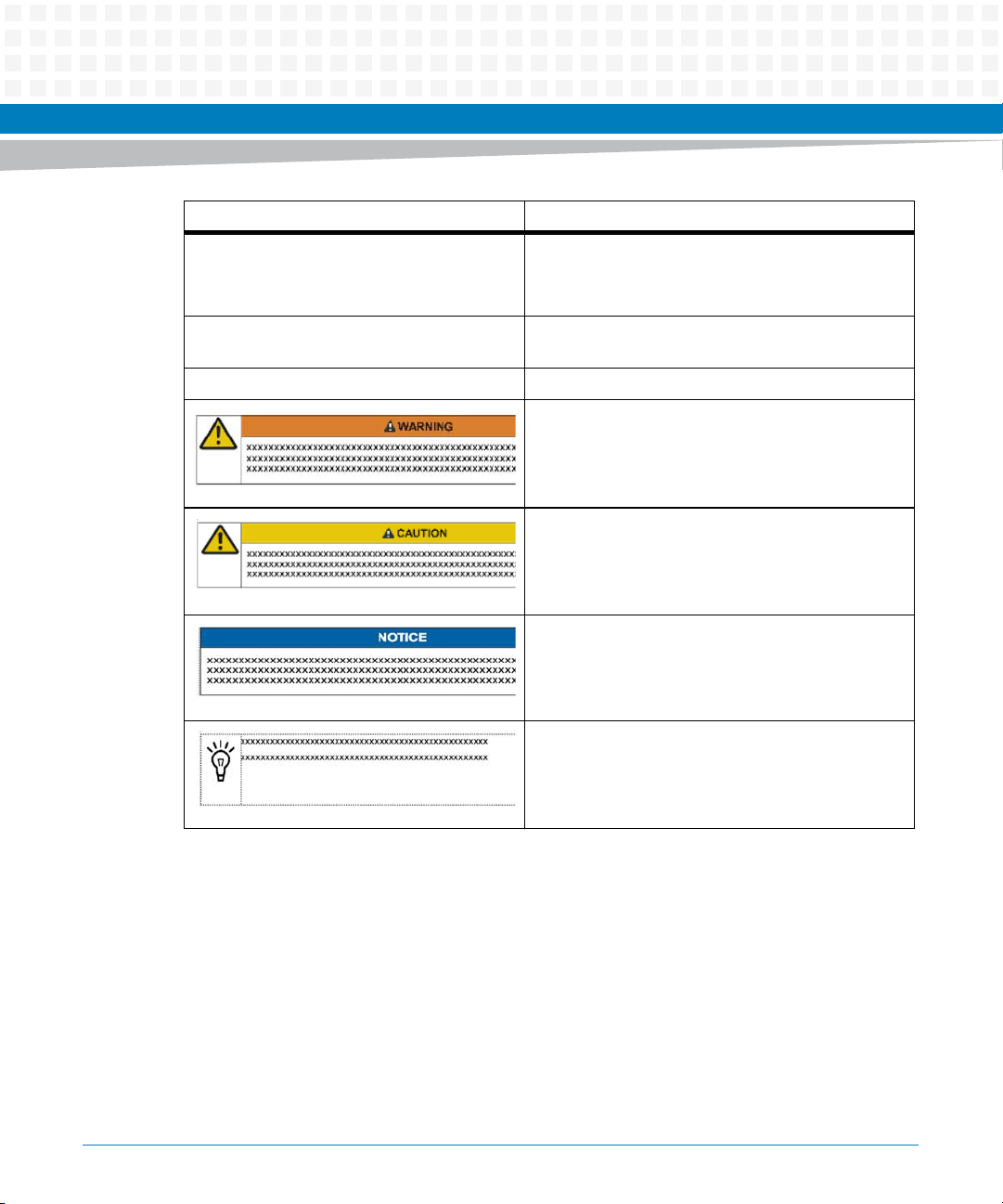
Conventions
The following table describes the conventions used throughout this manual.
About this Manual
14
Notation Description
0x00000000 Typical notation for hexadecimal numbers (digits are
0 through F), for example used for addresses and
offsets
0b0000 Same for binary numbers (digits are 0 and 1)
bold Used to emphasize a word
Screen Used for on-screen output and code related elements
or commands in body text
Courier + Bold Used to characterize user input and to separate it
from system output
Reference Used for references and for table and figure
descriptions
File > Exit Notation for selecting a submenu
<text> Notation for variables and keys
[text] Notation for software buttons to click on the screen
and parameter description
... Repeated item for example node 1, node 2, ..., node
12
MVME8100 / MVME8110 Installation and Use (6806800P25G)
Notation Description
About this Manual
.
.
.
.. Ranges, for example: 0..4 means one of the integers
| Logical OR
Omission of information from example/command
that is not necessary at the time being
0,1,2,3, and 4 (used in registers)
Indicates a hazardous situation which, if not avoided,
could result in death or serious injury
Indicates a hazardous situation which, if not avoided,
may result in minor or moderate injury
Indicates a property damage message
No danger encountered. Pay attention to important
information
MVME8100 / MVME8110 Installation and Use (6806800P25G)
15
About this Manual
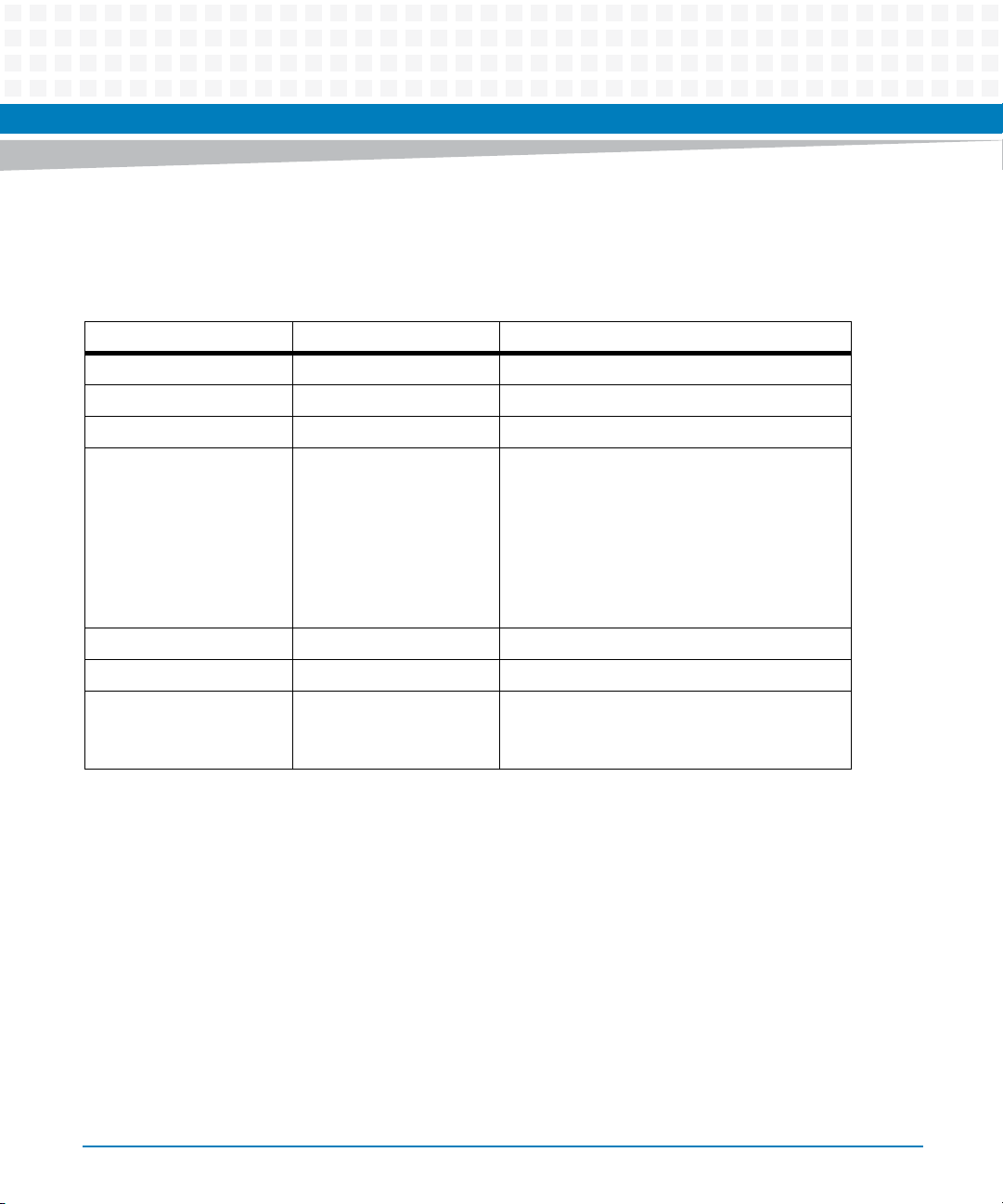
Summary of Changes
This is the first edition of the MVME8100 / MVME8110 Single Board Computer Installation and
Use.
Part Number Publication Date Description
6806800P25A May 2012 First edition
6806800P25B November 2012 GA release
6806800P25C December 2012 Updated Standard Compliances on page 22
6806800P25D September 2013 Updated Table 1-3, Table 1-4, Table 2-2, Table
2-4, PMC/XMC Installation on page 42, Table 3-3
on page 55, and Table 3-6 on page 58.
Added Figure 2-2 on page 36, SATA Installation
on page 45, Figure 2-4 on page 47, Figure 3-2
on page 53, Interrupt Controller Assignments on
page 91 and GPIO Electrical Characteristics on
page 92.
About this Manual
6806800P25E December 2013 Added Chapter 5, Boot System, on page 95.
6806800P25F June 2014 Re- branded to Artesyn template.
6806800P25G September 2014 Changed title as MVME8100 / MVME8110.
Added information about MVME8110 and
Declaration of Conformity.
16
MVME8100 / MVME8110 Installation and Use (6806800P25G)
Introduction
1.1 Features
The MVME8100 Single Board Computer is a VMEbus board based on the Freescale QorIQ
P5020 processor. It is a high performance 6U VME/VXS board targeted towards high-end
military and industrial automation applications using VMEbus. The MVME8100 is compliant
with the VITA standards VMEbus, 2eSST, and PCI-X.
The MVME8110 is a single core non-VXS version of the MVME8100 board based on Freescale
P5010 QorIQ processor. It runs at 1.2Ghz with 2GB DDR3. The MVME8110 can accommodate
2PMC/XMC.
The MVME8110 has MVME8110-RTM which is a reduced version of the VXS1-RTM1.
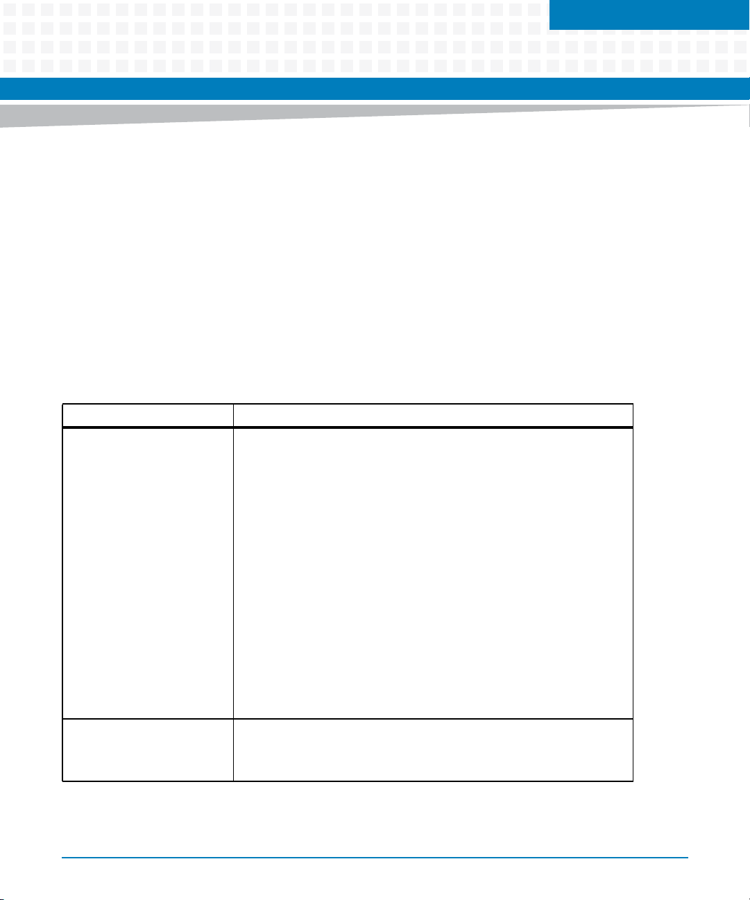
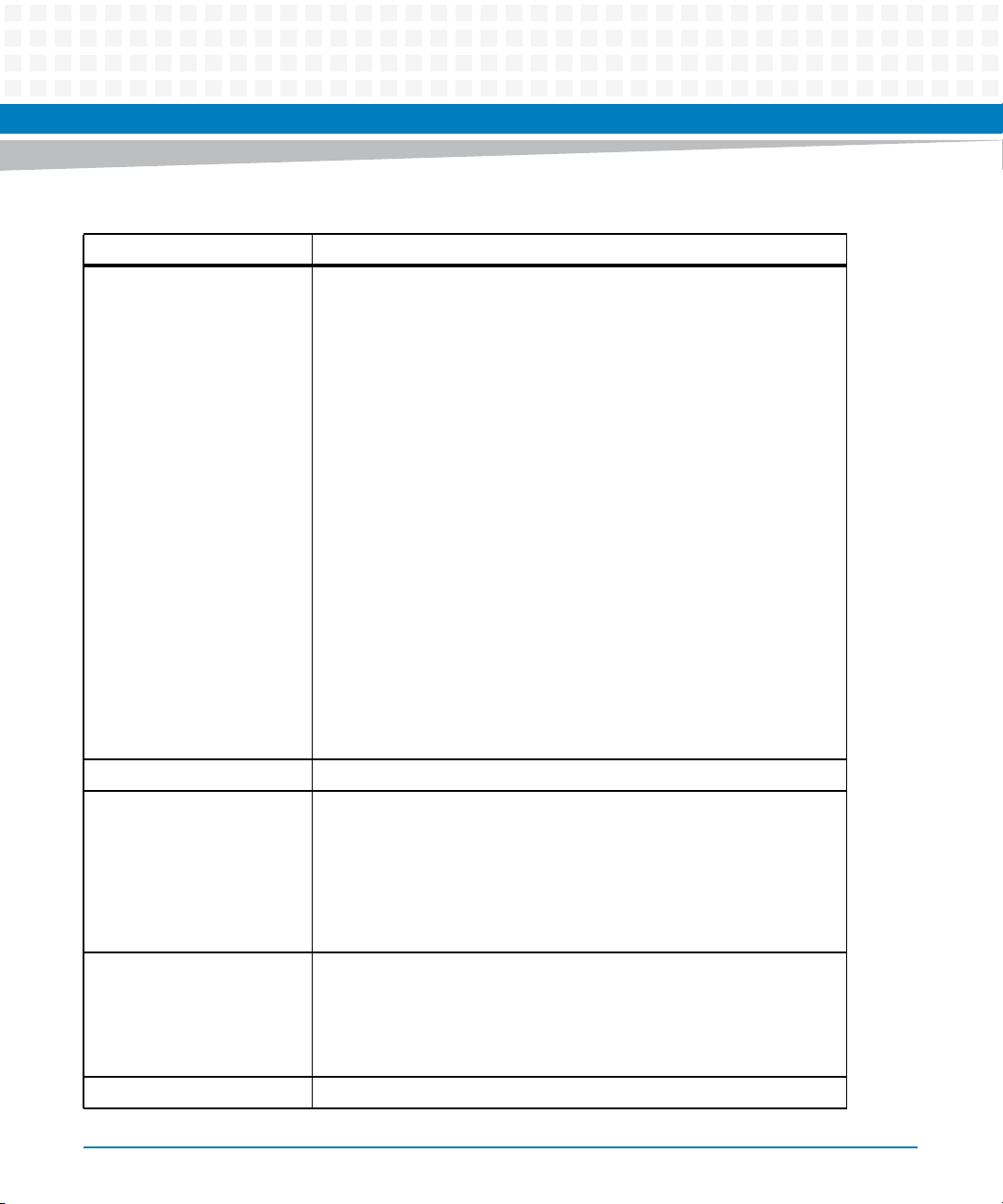
Table 1-1 Features List of MVME8100
Function Features
Chapter 1
Processor
(Subset of P5020 features
used on MVME8100)
System Memory Two banks of DDR3 SDRAM with ECC
Freescale QorIQ P5020
Two e5500 Power Architecture cores
Five Gigabit Ethernet controllers (SGMII and RGMII interfaces)
Two 64-bit DDR3/3L SDRAM memory controllers with ECC
Multicore Programmable Interrupt Controller (PIC)
Four I2C controllers
Two 4-pin UARTs
Two 4-channel DMA engines
Enhanced local bus controller (eLBC)
Two PCI Express controller/ports
One Serial Rapid IO controller/ports (SRIO port) v1.3-compliant with
features of v2.1
Enhanced secure digital host controller (SD/MMC)
Enhance Serial Peripheral Interfaces (eSPI)
Two high-speed USB 2.0 controllers with integrated PHYs
Total 4 GB (2GB per Bank)
1333 MHz DDR3 data rate
MVME8100 / MVME8110 Installation and Use (6806800P25G)
17
Introduction
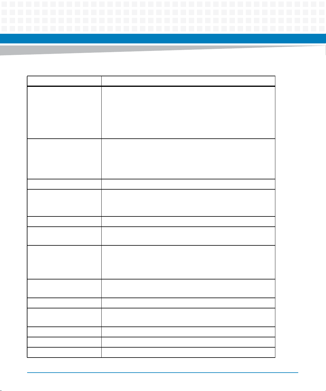
Table 1-1 Features List of MVME8100 (continued)
Function Features
SM Bus One 512 Kbit user configuration serial EEPROM
256B SPD EEPROMs
One 64 Kbit VPD EEPROM
RTC with battery backup
Temperature Sensors
RTM and XMC VPD EERPOMs
FLASH Two soldered SPI FLASH, 8MB each, switchable for uboot
primary/backup support
Hardware switch or Software bit write protection for entire logical
bank
Eight GB eMMC Flash
NVRAM 512 KB MRAM
PCI Express Two 4X Ports to VXS backplane P0 (muxed with SRIO ports)
One 8X Port to PMC/XMC Site 1
One 4X Port to PMC/XMC Site 2
SRIO Two 4X Ports to VXS backplane P0 (muxed with PCIe ports)
USB One USB 2.0 for front panel I/O
Two USBs 2.0 for backplane RTM I/O
Ethernet One 10/100/1000BASE-T Ethernet port to front panel (only in air
cooled variant)
Two 10/100/1000BASE-T Ethernet channels to P2 / RTM
Two 1000BASE-BX Ethernet SERDES channels to P0 backplane / RTM
Serial Ports One RS232/422/485 console port to front panel or P2 / RTM
Up to 4 RS232/422/485 COM ports to P2/ RTM
VME Bus VME64x and 2eSST
Timers Eight 32-bit timers in CPU
Watchdog timer in CPU
PMC/XMC Two PMC/XMC sites with 64-bit PMCIO on Site 1
SATA SSD Option for one 2.5 inch SATA drive (PMC/XMC Site 2)
GPIO Interface Four GPIOs to RTM
18
MVME8100 / MVME8110 Installation and Use (6806800P25G)
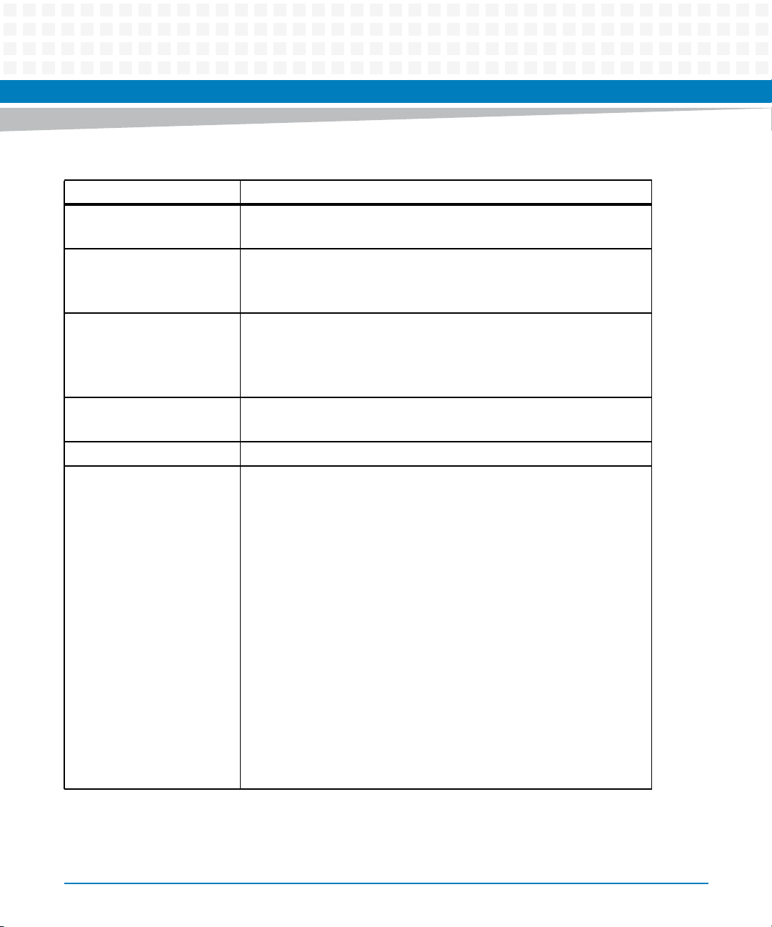
Table 1-1 Features List of MVME8100 (continued)
Function Features
VXS Interface VXS (VITA 41) Specification compliant
Support backplane P0 connector
Form Factor Standard 6U, one slot
Support 0.8, and 0.85 inch slot chassis
Support heat frame on both sides for Conduction cooled board
Miscellaneous One front panel RESET Switch
LED front panel status indicators: four user/fail/ready LEDs
Planar status indicators
Boundary scan support
Software Support VxWorks OS support
Linux OS support
RTM Compatible with RTM (assembly # 0106852M***)
Introduction
I/O One micro DB9 connector for console port on front panel
One USB2.0 type A connector on front panel
One front panel RJ45 connector with integrated LEDs for
10/100/1000 Ethernet channel
PMC/XMC site 1 front I/O and rear PMC I/O
PMC/XMC site two front I/O
Four Serial ports to P2/RTM, two with micro DB9 connectors on RTM
panel and two on planar headers
Two 10/100/1000BASE-T Ethernet channels to RJ45 connectors on
RTM panel
Two 1000 BASE-BX Ethernet SERDES channels to backplane
Two USB2.0 ports to RTM with USB type A connectors on RTM panel
One SATA port to RTM with eSATA connector on RTM
Four GPIOs to planar headers on RTM
Note: The front panel I/O connectors are available only in ENP1 (air
cooled variants). I/O signals in ENP4 (conduction cooled) variant are
accessed through P2 only.
MVME8100 / MVME8110 Installation and Use (6806800P25G)
19
Introduction
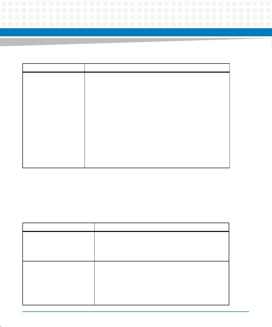
Table 1-2 Features List of MVME8110
Function Features
Processor
(Subset of P5010 features
used on MVME8110)
System Memory Up to 4GB Single-Channel DDR3-1333 memory with ECC
SM Bus One 512 Kbit user configuration serial EEPROM
Freescale QorIQ P5010,1.2Ghz, 15W TDP
One e500mc-64 core, 512kB L2 cache
1-Mbyte CoreNet platform cache with ECC
DDR3 memory controller (max 1333MT/s data rate [1200MT/s for
1.2GHz SKU])
4x PCIe 2.0 controllers
2x Serial RapidIO 2.1 controllers
2x SATA 2.0 controllers
2x USB 2.0 controllers with integrated PHYs
5x GbE controllers (SGMII/RGMII))
1x 10GbE controller
SD/MMC/eMMC controller
Local bus controller
SPI controller (4 CS#)
2x I2C controllers
Dual UART
RAID5/6 engine
SEC not present
Programmable interrupt controller
256B SPD EEPROMs
One 64 Kbit VPD EEPROM
RTC with battery backup
Temperature Sensors
RTM and XMC VPD EERPOMs
FLASH Two soldered SPI FLASH, 8MB each, switchable for uboot
primary/backup support
Hardware switch or Software bit write protection for entire logical
bank
Eight GB eMMC Flash
NVRAM 512 KB MRAM
20
MVME8100 / MVME8110 Installation and Use (6806800P25G)

Table 1-2 Features List of MVME8110 (continued)
Function Features
PCI Express One 8X Port to PMC/XMC Site 1
One 4X Port to PMC/XMC Site 2
USB One USB 2.0 for front panel I/O
Two USBs 2.0 for backplane RTM I/O
Ethernet One 10/100/1000BASE-T Ethernet port to front panel (only in air
cooled variant)
Two 10/100/1000BASE-T Ethernet channels to P2 / RTM
Serial Ports One RS232/422/485 console port to front panel or P2 / RTM
Up to 4 RS232/422/485 COM ports to P2/ RTM
VME Bus VME64x and 2eSST
Timers Eight 32-bit timers in CPU
Watchdog timer in CPU
Introduction
PMC/XMC Two PMC/XMC sites with 64-bit PMCIO on Site 1
SATA SSD Option for one 2.5 inch SATA drive (PMC/XMC Site 2)
GPIO Interface Two GPIOs to RTM
Form Factor Standard 6U, one slot
Support 0.8, and 0.85 inch slot chassis
Support heat frame on both sides for Conduction cooled board
Miscellaneous One front panel RESET Switch
LED front panel status indicators: four user/fail/ready LEDs
Planar status indicators
Boundary scan support
Software Support VxWorks OS support
Linux OS supports 32 bit
RTM Compatible with RTM (assembly # 0106852****)
MVME8100 / MVME8110 Installation and Use (6806800P25G)
21
Introduction
Table 1-2 Features List of MVME8110 (continued)
Function Features
I/O One micro DB9 connector for console port on front panel
One USB2.0 type A connector on front panel
One front panel RJ45 connector with integrated LEDs for
10/100/1000 Ethernet channel
PMC/XMC site 1 front I/O and rear PMC I/O
PMC/XMC site two front I/O
Four Serial ports to P2/RTM, two with micro DB9 connectors on RTM
panel and two on planar headers
Two 10/100/1000BASE-T Ethernet channels to RJ45 connectors on
RTM panel
Two 1000 BASE-BX Ethernet SERDES channels to backplane
Two USB2.0 ports to RTM with USB type A connectors on RTM panel
One SATA port to RTM with eSATA connector on RTM
Two GPIOs to planar headers on RTM
1.2 Standard Compliances
The MVME8100 / MVME8110 is designed to be CE compliant and to meet the following
standard requirements.
Table 1-3 Board Standard Compliances
Standard Description
UL 60950-1
EN 60950-1
IEC 60950-1
CAN/CSA C22.2 No 60950-1
CISPR 22
EN 55022
EN 55024
FCC Class A
VCCI Japan
AS/NZS CISPR 22
22
Safety Requirements (legal)
EMC requirements (legal) on system level (predefined Artesyn
Embedded Technologies system)
MVME8100 / MVME8110 Installation and Use (6806800P25G)
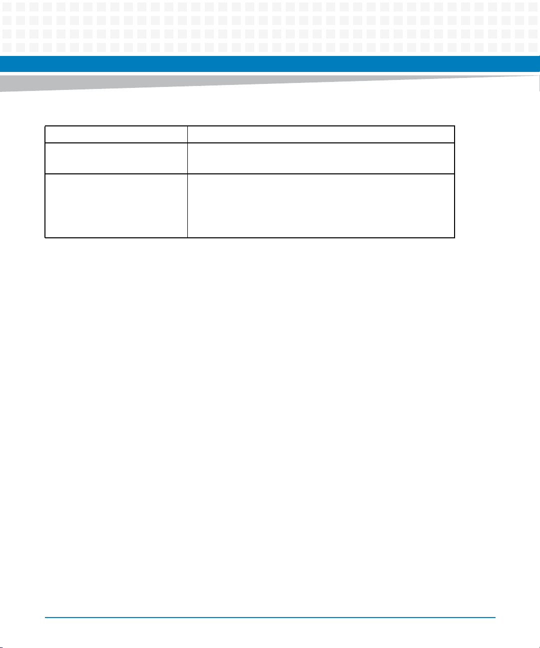
Table 1-3 Board Standard Compliances (continued)
Standard Description
Environmental Requirements
ETSI EN 300 019 series
Directive 2002/95/EC Directive on the restriction of the use of certain hazardous
substances in electrical and electronic equipment (RoHS).
The ENP1 version complies with RoHs 6 of 6. The ENP4 version
complies with RoHS 5 of 6 due to lead solder used in the ENP4 heat
frame.
Introduction
MVME8100 / MVME8110 Installation and Use (6806800P25G)
23
Introduction
Figure 1-1 Declaration of Conformity of MVME8100
EC Declaration of Conformity
According to EN 17050-1:2004
Manufacturer’s Name:
Manufacturer’s Address:
Declares that the following product, in accordance with the requirements of 2004/108/EC, 2006/95/EC, 2011/65/
EU and their amending directives,
Product:
Model Name/Number:
has been designed and manufactured to the following specifications:
EN55022: 2010
EN55024:2010
IEC 60950-1:2005 (2nd Edition), EN60950-1:2006+A11:2009
2011/65/EU RoHS Directive
As manufacturer we hereby declare that the product named above has been designed to comply with the relevant sections of the above referenced specifications. This product complies with the essential health and safety
requirements of the above specified directives. We have an internal production control system that ensures
compliance between the manufactured products and the technical documentation.
Artesyn Embedded Computing
Embedded Computing
Zhongshan General Carton Box Factory Co. Ltd. No 62, Qi
Guan Road West, Shiqi District, 528400 Zhongshan City
Guangdong, PRC
MVME8100 Series VMEbus Single Board Computer
MVME8100-202180404. MVME8100-202200401E,
MVME8100-202200401S, MVME8100-202200404
24
___________________________________________________ ___04/028/2014______
Tom Tuttle, Manager, Product Testing Services Date (MM/DD/YYYY)
MVME8100 / MVME8110 Installation and Use (6806800P25G)
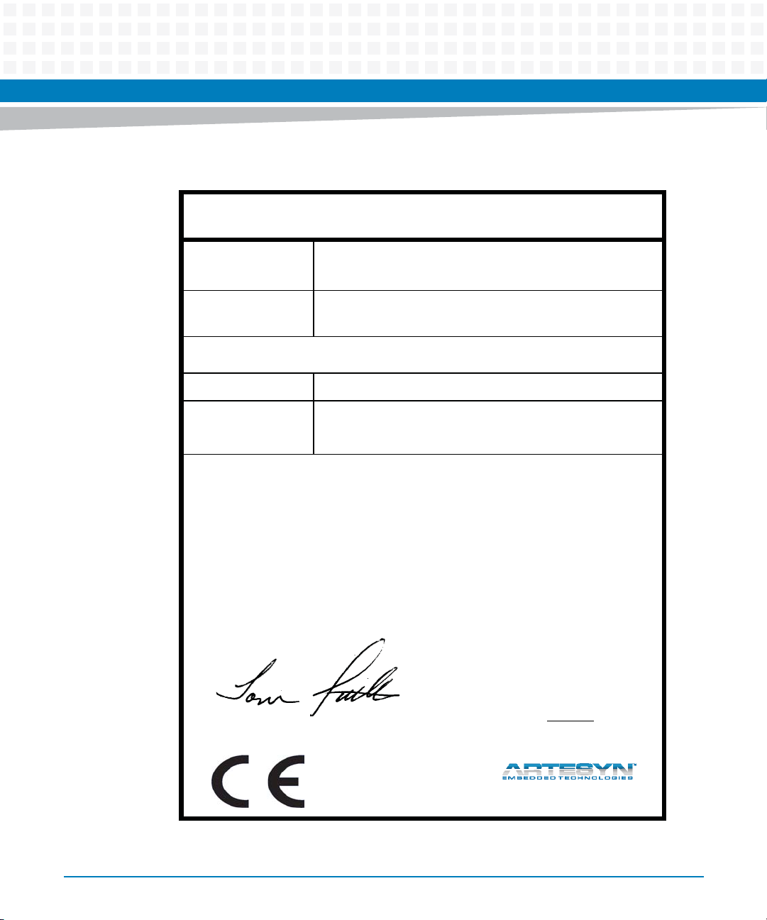
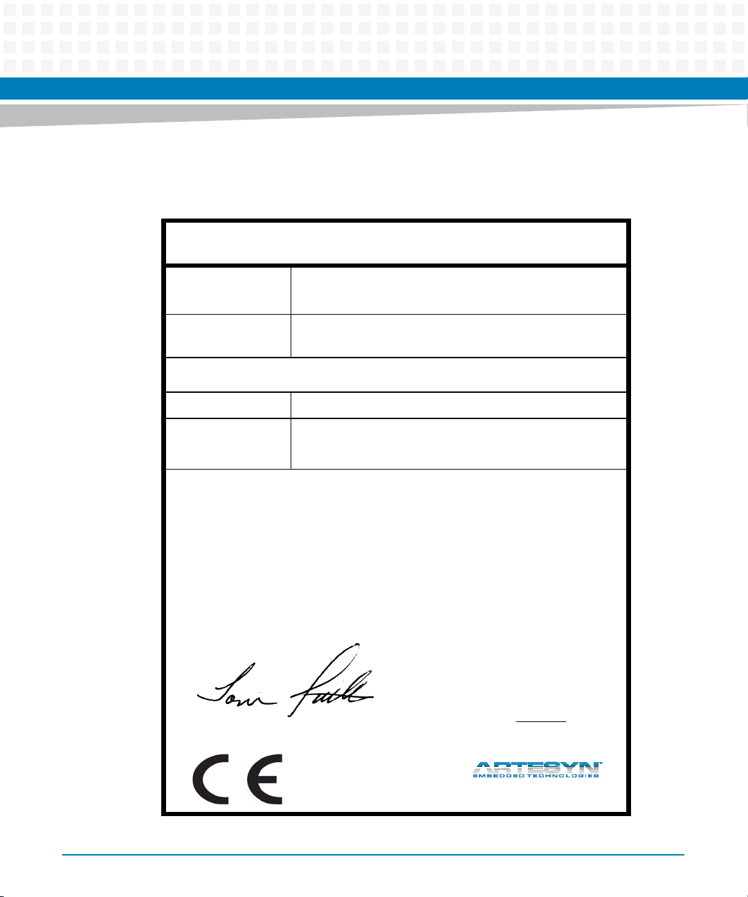
Figure 1-2 Declaration of Conformity of MVME8110
E
C Declaration of Conformity
According to EN 17050-1:2004
Introduction
Manufacturer’s Name:
Manufacturer’s Address:
Declares that the following product, in accordance with the requirements of 2004/108/EC, 2011/65/EU and their
amending directives,
Product:
Model Name/Number:
has been designed and manufactured to the following specifications:
EN55022: 2010
EN55024: 2010 Edition 2
2011/65/EU RoHS Directive
As manufacturer we hereby declare that the product named above has been designed to comply with the relevant sections of the above referenced specifications. This product complies with the essential health and safety
requirements of the above specified directives. We have an internal production control system that ensures
compliance between the manufactured products and the technical documentation.
Artesyn Embedded Computing
Embedded Computing
Zhongshan General Carton Box Factory Co. Ltd. No 62, Qi
Guan Road West, Shiqi District, 528400 Zhongshan City
Guangdong, PRC
MVME8110 Series VMEbus Single Board Computer
MVME8110-01E, MVME8110-01S, MVME8110-RTM
___________________________________________________ ___
Tom Tuttle, Manager, Product Testing Services Date (MM/DD/YYYY)
MVME8100 / MVME8110 Installation and Use (6806800P25G)
09/18/2014______
25
Introduction
1.3 Mechanical Data
The MVME8100 is a full 6U board with added mounting holes to support an ENP4 board
variant. The MVME8100 / MVME8110 will occupy a single VME card slot.
Table 1-4 provides details on the board’s mechanical data.
Table 1-4 Mechanical Data
Characteristic Value
Height 233.44 mm (9.2inches)
Depth 160.0 mm (6.3 inches)
Front Panel Height 261.8 mm (10.3 inches)
Width 19.8 mm (0.8 inches)
Maximum Component Height 14.8 mm (0.58 inches)
Weight (estimated) 0.58 Kg (ENP1)
0.90 Kg (ENP4)
1.4 Ordering Information
When ordering board variants or board accessories, use the order numbers given in the
following tables.
1.4.1 Supported Board Models
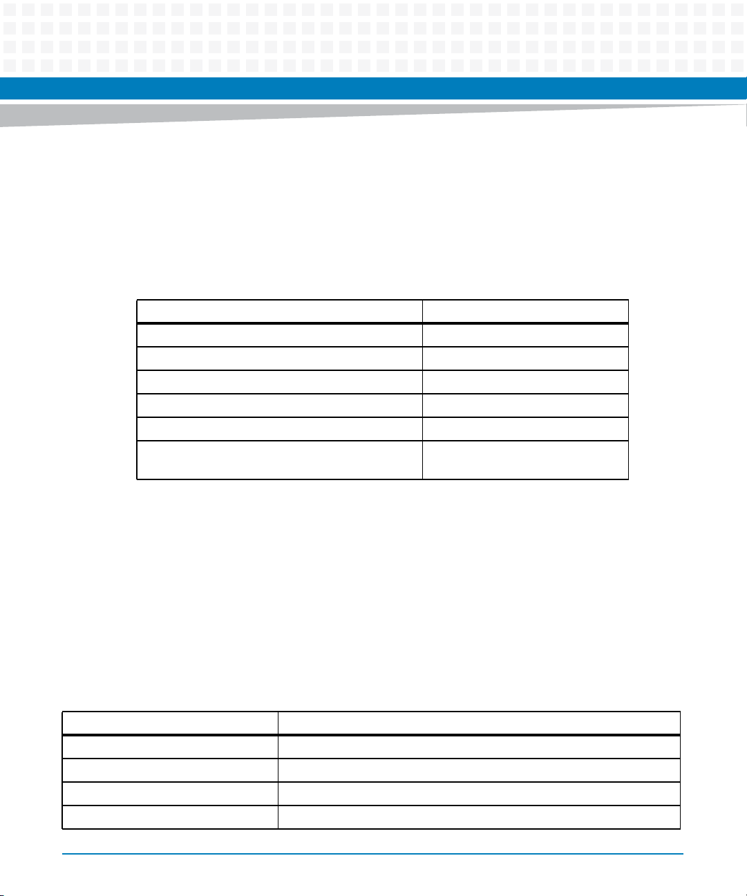
Table 1-5 Board Variants
Marketing # Processor
MVME8100-202200401E P5020 2.0GHz 28W, 4GB DDR3, VXS, 2 PMC/XMC, IEEE, ENP1
MVME8100-202200401S P5020 2.0GHz 28W, 4GB DDR3, VXS, 2 PMC/XMC, SCANBE, ENP1
MVME8100-202200404 P5020 1.8GHz 27W, 4GB DDR3, VXS, 2 PMC/XMC, ENP4
MVME8110-01E P5010 1.2GHZ, 2GB DDR3, 2PMC/XMC, ENP1 IEEE
26
MVME8100 / MVME8110 Installation and Use (6806800P25G)
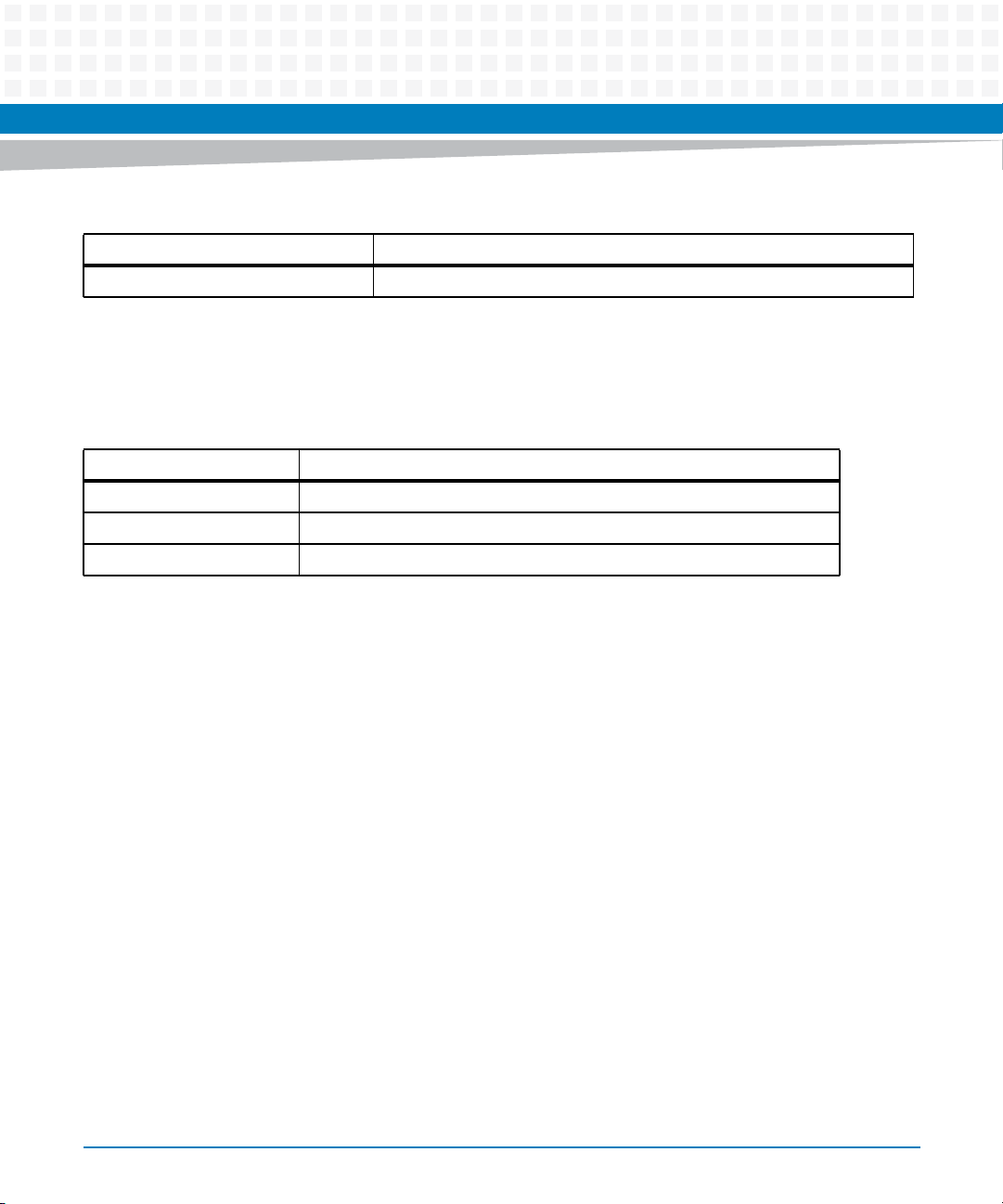
Table 1-5 Board Variants (continued)
Marketing # Processor
MVME8110-01S P5010 1.2GHZ, 2GB DDR3, 2PMC/XMC, ENP1 SCANBE
1.4.2 Board Accessories
This table lists the available expansion and transition modules for the MVME8100 /
MVME8110.
Model Number Description
VXS1-RTM1 RTM for MVME8100 (supports ENP1 specifications only)
MVME8100-HDMNTKIT4 SSD Mounting kit (HDD not included)
MVME8110-RTM RTM FOR THE MVME8110
Introduction
MVME8100 / MVME8110 Installation and Use (6806800P25G)
27

Introduction
28
MVME8100 / MVME8110 Installation and Use (6806800P25G)
Hardware Preparation and Installation
2.1 Overview
This chapter provides startup and safety instructions related to this product, hardware
preparation instruction that includes default switch settings. System considerations and
installation instructions for the baseboard, PMC, XMC, and Rear Transition Module (RTM) are
also described in this chapter.
A fully implemented MVME8100 / MVME8110 consists of the baseboard plus:
Two single-wide or one double-wide PCI Mezzanine Card (PMC) slot for added versatility.
One rear transition module for support of the mapped I/O from the MVME8100 /
MVME8110 baseboard to the P2 connector.
Up to two optional XMC cards (in place of PMC modules).
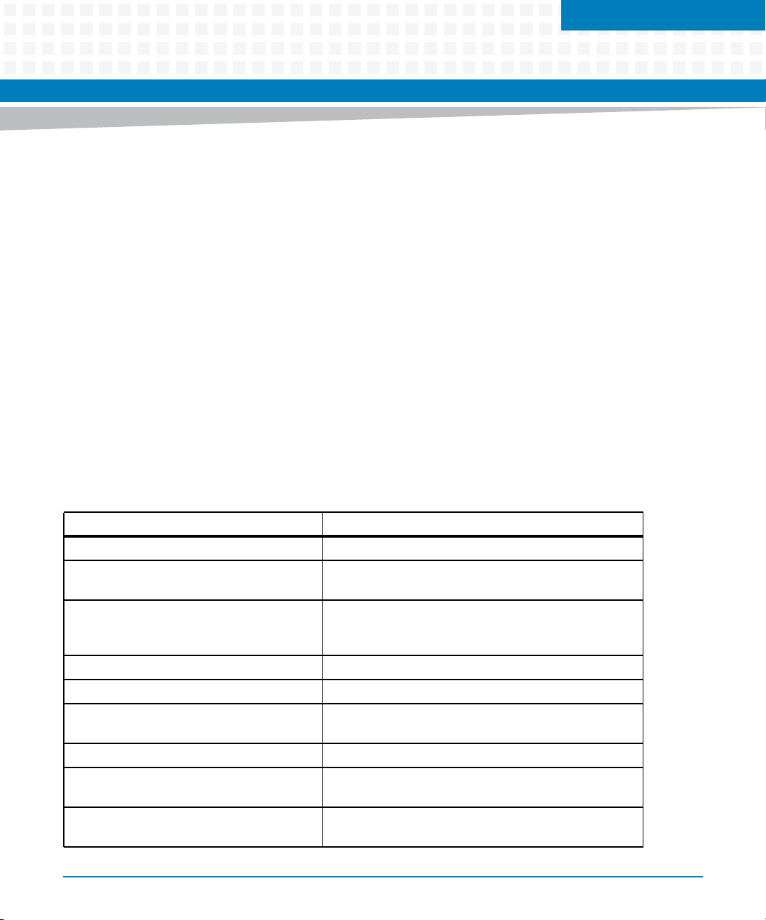
The following table lists the things you need to do before using this board and explains where
you can find the information for performing each step. Be sure to read this entire chapter,
including all Caution and Warning notes, before you begin.
Chapter 2
Table 2-1 Startup Overview
Task Page
Unpack the hardware. Unpacking and Inspecting the Board on page 30
Configure the hardware by setting jumpers
on the board and RTM.
Install the RTM (VXS1-RTM1) of MVME8100
or MVME8110-RTM of MVME8110 in the
chassis.
Install PMC module (if required). Installing Accessories on page 41
Install XMC module (if required). Installing Accessories on page 41
Install the MVME8100 / MVME8110 in the
chassis.
Attach cabling and apply power. Completing the Installation on page 50
Install PIM on transition module (if required). Refer VXS1-RTM1and MVME8110-RTM Installation and Use
Examine and/or change environmental
parameters.
MVME8100 / MVME8110 Installation and Use (6806800P25G)
Configuring the Board on page 34
Rear Transition Module on page 41
Installing and Removing the Board on page 48
manual.
MVME8100 / MVME8110 Single Board Computer
Programmer’s Reference
29
Hardware Preparation and Installation
Table 2-1 Startup Overview (continued)
Task Page
Program the board as needed for your
applications.
MVME8100 / MVME8110 Single Board Computer
Programmer’s Reference
2.2 Unpacking and Inspecting the Board
Read all notices and cautions prior to unpacking the product.
Damage of Circuits
Electrostatic discharge and incorrect installation and removal can damage circuits or
shorten their life.
Before touching the board or electronic components, make sure that you are working in an
ESD-safe environment.
30
Shipment Inspection
To inspect the shipment, perform the following steps:
1. Verify that you have received all items of your shipment.
2. Check for damage and report any damage or differences to customer service.
3. Remove the desiccant bag shipped together with the board and dispose of it
according to your country’s legislation.
The product is thoroughly inspected before shipment. If any damage occurred during
transportation or any items are missing, contact customer service immediately.
MVME8100 / MVME8110 Installation and Use (6806800P25G)
 Loading...