

Page 1

ATCA-MF106
Installation and Use
P/N: 6806800M62B
September 2014
Page 2

©
Copyright 2014 Artesyn Embedded Technologies, Inc.
All rights reserved.
Trademarks
Artesyn Embedded Technologies, Artesyn and the Artesyn Embedded Technologies logo are trademarks and service marks of
Artesyn Embedded Technologies, Inc.© 2014 Artesyn Embedded Technologies, Inc. All other product or service names are the
property of their respective owners.
Intel® is a trademark or registered trademark of Intel Corporation or its subsidiaries in the United States and other countries.
Java™ and all other Java-based marks are trademarks or registered trademarks of Oracle America, Inc. in the U.S. and other countries.
Microsoft®, Windows® and Windows Me® are registered trademarks of Microsoft Corporation; and Windows XP™ is a trademark of
Microsoft Corporation.
PICMG®, CompactPCI®, AdvancedTCA™ and the PICMG, CompactPCI and AdvancedTCA logos are registered trademarks of the PCI
Industrial Computer Manufacturers Group.
UNIX® is a registered trademark of The Open Group in the United States and other countries.
Notice
While reasonable efforts have been made to assure the accuracy of this document, Artesyn assumes no liability resulting from any
omissions in this document, or from the use of the information obtained therein. Artesyn reserves the right to revise this document
and to make changes from time to time in the content hereof without obligation of Artesyn to notify any person of such revision or
changes.
Electronic versions of this material may be read online, downloaded for personal use, or referenced in another document as a URL to
an Artesyn website. The text itself may not be published commercially in print or electronic form, edited, translated, or otherwise
altered without the permission of Artesyn.
It is possible that this publication may contain reference to or information about Artesyn products (machines and programs),
programming, or services that are not available in your country. Such references or information must not be construed to mean that
Artesyn intends to announce such Artesyn products, programming, or services in your country.
Limited and Restricted Rights Legend
If the documentation contained herein is supplied, directly or indirectly, to the U.S. Government, the following notice shall apply
unless otherwise agreed to in writing by Artesyn.
Use, duplication, or disclosure by the Government is subject to restrictions as set forth in subparagraph (b)(3) of the Rights in
Technical Data clause at DFARS 252.227-7013 (Nov. 1995) and of the Rights in Noncommercial Computer Software and
Documentation clause at DFARS 252.227-7014 (Jun. 1995).
Contact Address
Artesyn Embedded Technologies Artesyn Embedded Technologies
Marketing Communications
2900 S. Diablo Way, Suite 190
Tempe, Arizona 85282
Lilienthalstr. 17-19
85579 Neubiberg/Munich
Germany
Page 3

Contents
Contents
About this Manual . . . . . . . . . . . . . . . . . . . . . . . . . . . . . . . . . . . . . . . . . . . . . . . . . . . . . . . . . . . . . . . . . . . . . . . 11
Safety Notes . . . . . . . . . . . . . . . . . . . . . . . . . . . . . . . . . . . . . . . . . . . . . . . . . . . . . . . . . . . . . . . . . . . . . . . . . . . . . 17
Sicherheitshinweise . . . . . . . . . . . . . . . . . . . . . . . . . . . . . . . . . . . . . . . . . . . . . . . . . . . . . . . . . . . . . . . . . . . . . . 21
1 Introduction . . . . . . . . . . . . . . . . . . . . . . . . . . . . . . . . . . . . . . . . . . . . . . . . . . . . . . . . . . . . . . . . . . . . . . . . . 27
1.1 Overview . . . . . . . . . . . . . . . . . . . . . . . . . . . . . . . . . . . . . . . . . . . . . . . . . . . . . . . . . . . . . . . . . . . . . . . . . . 27
1.2 Hardware . . . . . . . . . . . . . . . . . . . . . . . . . . . . . . . . . . . . . . . . . . . . . . . . . . . . . . . . . . . . . . . . . . . . . . . . . . 30
1.2.1 Shelf Manager Hardware . . . . . . . . . . . . . . . . . . . . . . . . . . . . . . . . . . . . . . . . . . . . . . . . . . . . . . 31
1.2.2 Hub Hardware . . . . . . . . . . . . . . . . . . . . . . . . . . . . . . . . . . . . . . . . . . . . . . . . . . . . . . . . . . . . . . . 34
1.3 Shelf Management Software . . . . . . . . . . . . . . . . . . . . . . . . . . . . . . . . . . . . . . . . . . . . . . . . . . . . . . . . . 34
1.3.1 HPI Based Shelf Management. . . . . . . . . . . . . . . . . . . . . . . . . . . . . . . . . . . . . . . . . . . . . . . . . . 35
1.3.2 Remote Access . . . . . . . . . . . . . . . . . . . . . . . . . . . . . . . . . . . . . . . . . . . . . . . . . . . . . . . . . . . . . . 36
1.3.2.1 Remote HPI . . . . . . . . . . . . . . . . . . . . . . . . . . . . . . . . . . . . . . . . . . . . . . . . . . . . . . . . 36
1.3.2.2 RMCP . . . . . . . . . . . . . . . . . . . . . . . . . . . . . . . . . . . . . . . . . . . . . . . . . . . . . . . . . . . . . . 37
1.3.3 Software Upgrade Management . . . . . . . . . . . . . . . . . . . . . . . . . . . . . . . . . . . . . . . . . . . . . . . 38
1.3.4 High-Availability Management. . . . . . . . . . . . . . . . . . . . . . . . . . . . . . . . . . . . . . . . . . . . . . . . . 38
1.3.4.1 Redundancy . . . . . . . . . . . . . . . . . . . . . . . . . . . . . . . . . . . . . . . . . . . . . . . . . . . . . . . . 38
1.3.4.2 Network Management . . . . . . . . . . . . . . . . . . . . . . . . . . . . . . . . . . . . . . . . . . . . . . 39
1.4 Standard Compliances . . . . . . . . . . . . . . . . . . . . . . . . . . . . . . . . . . . . . . . . . . . . . . . . . . . . . . . . . . . . . . 40
1.5 Ordering Information . . . . . . . . . . . . . . . . . . . . . . . . . . . . . . . . . . . . . . . . . . . . . . . . . . . . . . . . . . . . . . . 42
2 ATCA-MF106 Hardware . . . . . . . . . . . . . . . . . . . . . . . . . . . . . . . . . . . . . . . . . . . . . . . . . . . . . . . . . . . . . . . 43
2.1 Overview . . . . . . . . . . . . . . . . . . . . . . . . . . . . . . . . . . . . . . . . . . . . . . . . . . . . . . . . . . . . . . . . . . . . . . . . . . 43
2.2 Payload Hardware . . . . . . . . . . . . . . . . . . . . . . . . . . . . . . . . . . . . . . . . . . . . . . . . . . . . . . . . . . . . . . . . . . 44
2.2.1 Ethernet Interfaces . . . . . . . . . . . . . . . . . . . . . . . . . . . . . . . . . . . . . . . . . . . . . . . . . . . . . . . . . . . 44
2.2.2 Redundancy Interfaces . . . . . . . . . . . . . . . . . . . . . . . . . . . . . . . . . . . . . . . . . . . . . . . . . . . . . . . 45
2.2.3 Block Transfer Interface . . . . . . . . . . . . . . . . . . . . . . . . . . . . . . . . . . . . . . . . . . . . . . . . . . . . . . . 45
2.3 Shelf Management Controller . . . . . . . . . . . . . . . . . . . . . . . . . . . . . . . . . . . . . . . . . . . . . . . . . . . . . . . . 45
2.3.1 IPMB0 Interface . . . . . . . . . . . . . . . . . . . . . . . . . . . . . . . . . . . . . . . . . . . . . . . . . . . . . . . . . . . . . . 45
2.3.2 IPMC Standard Functions. . . . . . . . . . . . . . . . . . . . . . . . . . . . . . . . . . . . . . . . . . . . . . . . . . . . . . 46
2.4 Power Supply . . . . . . . . . . . . . . . . . . . . . . . . . . . . . . . . . . . . . . . . . . . . . . . . . . . . . . . . . . . . . . . . . . . . . . 46
2.4.1 Onboard and External Supply . . . . . . . . . . . . . . . . . . . . . . . . . . . . . . . . . . . . . . . . . . . . . . . . . . 46
ATCA-MF106 Installation and Use (6806800M62B)
3
Page 4

Contents
Contents
Contents
2.4.2 Power Supply Holdup. . . . . . . . . . . . . . . . . . . . . . . . . . . . . . . . . . . . . . . . . . . . . . . . . . . . . . . . . 47
2.5 Gigabit Ethernet Hub . . . . . . . . . . . . . . . . . . . . . . . . . . . . . . . . . . . . . . . . . . . . . . . . . . . . . . . . . . . . . . . 48
2.6 Frame Ground and ESD . . . . . . . . . . . . . . . . . . . . . . . . . . . . . . . . . . . . . . . . . . . . . . . . . . . . . . . . . . . . . . 49
3 Controls, Indicators and Connectors . . . . . . . . . . . . . . . . . . . . . . . . . . . . . . . . . . . . . . . . . . . . . . . . . . . . 51
3.1 Face Plate . . . . . . . . . . . . . . . . . . . . . . . . . . . . . . . . . . . . . . . . . . . . . . . . . . . . . . . . . . . . . . . . . . . . . . . . . 51
3.1.1 LEDs. . . . . . . . . . . . . . . . . . . . . . . . . . . . . . . . . . . . . . . . . . . . . . . . . . . . . . . . . . . . . . . . . . . . . . . . 51
3.1.2 Ethernet Connectors . . . . . . . . . . . . . . . . . . . . . . . . . . . . . . . . . . . . . . . . . . . . . . . . . . . . . . . . . 52
3.2 Console Connector . . . . . . . . . . . . . . . . . . . . . . . . . . . . . . . . . . . . . . . . . . . . . . . . . . . . . . . . . . . . . . . . . 52
3.3 Sensors . . . . . . . . . . . . . . . . . . . . . . . . . . . . . . . . . . . . . . . . . . . . . . . . . . . . . . . . . . . . . . . . . . . . . . . . . . . 53
4 Board Exchange . . . . . . . . . . . . . . . . . . . . . . . . . . . . . . . . . . . . . . . . . . . . . . . . . . . . . . . . . . . . . . . . . . . . . . 55
4.1 Introduction . . . . . . . . . . . . . . . . . . . . . . . . . . . . . . . . . . . . . . . . . . . . . . . . . . . . . . . . . . . . . . . . . . . . . . . 55
4.2 Before Installation . . . . . . . . . . . . . . . . . . . . . . . . . . . . . . . . . . . . . . . . . . . . . . . . . . . . . . . . . . . . . . . . . . 55
4.2.1 Requirements . . . . . . . . . . . . . . . . . . . . . . . . . . . . . . . . . . . . . . . . . . . . . . . . . . . . . . . . . . . . . . . 55
4.2.1.1 Environmental Requirements . . . . . . . . . . . . . . . . . . . . . . . . . . . . . . . . . . . . . . . . 56
4.2.1.2 Power Requirements . . . . . . . . . . . . . . . . . . . . . . . . . . . . . . . . . . . . . . . . . . . . . . . . 57
4.2.1.3 Required Equipment . . . . . . . . . . . . . . . . . . . . . . . . . . . . . . . . . . . . . . . . . . . . . . . . 58
4.2.2 Unpacking and Inspecting the Board . . . . . . . . . . . . . . . . . . . . . . . . . . . . . . . . . . . . . . . . . . . 58
4.3 Installing the Board . . . . . . . . . . . . . . . . . . . . . . . . . . . . . . . . . . . . . . . . . . . . . . . . . . . . . . . . . . . . . . . . . 59
4.3.1 Installing the Board. . . . . . . . . . . . . . . . . . . . . . . . . . . . . . . . . . . . . . . . . . . . . . . . . . . . . . . . . . . 60
4.3.2 Removing the Board. . . . . . . . . . . . . . . . . . . . . . . . . . . . . . . . . . . . . . . . . . . . . . . . . . . . . . . . . . 60
5 Shelf Manager File System. . . . . . . . . . . . . . . . . . . . . . . . . . . . . . . . . . . . . . . . . . . . . . . . . . . . . . . . . . . . . 63
5.1 Persistent File Support . . . . . . . . . . . . . . . . . . . . . . . . . . . . . . . . . . . . . . . . . . . . . . . . . . . . . . . . . . . . . . 63
5.1.1 Persistent File Support . . . . . . . . . . . . . . . . . . . . . . . . . . . . . . . . . . . . . . . . . . . . . . . . . . . . . . . . 63
5.1.2 Use Cases . . . . . . . . . . . . . . . . . . . . . . . . . . . . . . . . . . . . . . . . . . . . . . . . . . . . . . . . . . . . . . . . . . . 65
5.1.2.1 How to Make a File on the RAM Disk File System Persistent . . . . . . . . . . . . . . . 65
5.1.2.2 How to Remove a File from the Persistent File System . . . . . . . . . . . . . . . . . . . 66
5.1.2.3 How to Rollback Factory Configuration . . . . . . . . . . . . . . . . . . . . . . . . . . . . . . . . 66
5.1.2.4 Persistent Log Files . . . . . . . . . . . . . . . . . . . . . . . . . . . . . . . . . . . . . . . . . . . . . . . . . . 66
5.2 Log Files . . . . . . . . . . . . . . . . . . . . . . . . . . . . . . . . . . . . . . . . . . . . . . . . . . . . . . . . . . . . . . . . . . . . . . . . . . . 67
4
ATCA-MF106 Installation and Use (6806800M62B)
Page 5

Contents
6 Firmware Upgrade Facility . . . . . . . . . . . . . . . . . . . . . . . . . . . . . . . . . . . . . . . . . . . . . . . . . . . . . . . . . . . . 69
6.1 Overview . . . . . . . . . . . . . . . . . . . . . . . . . . . . . . . . . . . . . . . . . . . . . . . . . . . . . . . . . . . . . . . . . . . . . . . . . . 69
6.2 Firmware Recovery Image Files . . . . . . . . . . . . . . . . . . . . . . . . . . . . . . . . . . . . . . . . . . . . . . . . . . . . . . . 69
6.3 Backup Concept . . . . . . . . . . . . . . . . . . . . . . . . . . . . . . . . . . . . . . . . . . . . . . . . . . . . . . . . . . . . . . . . . . . . 69
6.4 fcu—Firmware Upgrade Command-Line Utility . . . . . . . . . . . . . . . . . . . . . . . . . . . . . . . . . . . . . . . . . 70
6.5 Upgrading Firmware . . . . . . . . . . . . . . . . . . . . . . . . . . . . . . . . . . . . . . . . . . . . . . . . . . . . . . . . . . . . . . . . 75
6.5.1 Upgrading CPU Firmware . . . . . . . . . . . . . . . . . . . . . . . . . . . . . . . . . . . . . . . . . . . . . . . . . . . . . 75
6.5.2 Upgrading the Device-Tree Blob . . . . . . . . . . . . . . . . . . . . . . . . . . . . . . . . . . . . . . . . . . . . . . . 75
6.5.3 Upgrading the Kernel. . . . . . . . . . . . . . . . . . . . . . . . . . . . . . . . . . . . . . . . . . . . . . . . . . . . . . . . . 76
6.5.4 Upgrading the Ramdisk . . . . . . . . . . . . . . . . . . . . . . . . . . . . . . . . . . . . . . . . . . . . . . . . . . . . . . . 76
6.5.5 Activating the Backup Boot Bank. . . . . . . . . . . . . . . . . . . . . . . . . . . . . . . . . . . . . . . . . . . . . . . 78
6.5.6 Upgrading IPMC Firmware . . . . . . . . . . . . . . . . . . . . . . . . . . . . . . . . . . . . . . . . . . . . . . . . . . . . 79
6.5.7 Example Upgrade Procedure . . . . . . . . . . . . . . . . . . . . . . . . . . . . . . . . . . . . . . . . . . . . . . . . . . 79
A Related Documentation . . . . . . . . . . . . . . . . . . . . . . . . . . . . . . . . . . . . . . . . . . . . . . . . . . . . . . . . . . . . . . . 83
A.1 Artesyn Embedded Technologies - Embedded Computing Documentation . . . . . . . . . . . . . . . . 83
A.2 Related Specifications . . . . . . . . . . . . . . . . . . . . . . . . . . . . . . . . . . . . . . . . . . . . . . . . . . . . . . . . . . . . . . . 83
ATCA-MF106 Installation and Use (6806800M62B)
5
Page 6

Contents
Contents
Contents
6
ATCA-MF106 Installation and Use (6806800M62B)
Page 7

List of Tables
Table 1-1 Standard Compliances . . . . . . . . . . . . . . . . . . . . . . . . . . . . . . . . . . . . . . . . . . . . . . . . . . . . . . . . . . 40
Table 1-2 Ordering Information . . . . . . . . . . . . . . . . . . . . . . . . . . . . . . . . . . . . . . . . . . . . . . . . . . . . . . . . . . . 42
Table 3-1 Face Plate LEDs . . . . . . . . . . . . . . . . . . . . . . . . . . . . . . . . . . . . . . . . . . . . . . . . . . . . . . . . . . . . . . . . 51
Table 3-2 COM 0 Front Panel Serial Port Pin-out Listing . . . . . . . . . . . . . . . . . . . . . . . . . . . . . . . . . . . . . . 52
Table 3-3 ATCA-MF106 Specific Sensors . . . . . . . . . . . . . . . . . . . . . . . . . . . . . . . . . . . . . . . . . . . . . . . . . . . 53
Table 4-1 Environmental Requirements . . . . . . . . . . . . . . . . . . . . . . . . . . . . . . . . . . . . . . . . . . . . . . . . . . . . 56
Table 4-2 DC Board Power Requirements . . . . . . . . . . . . . . . . . . . . . . . . . . . . . . . . . . . . . . . . . . . . . . . . . . 57
Table A-1 Artesyn Embedded Technologies - Embedded Computing Publications . . . . . . . . . . . . . . . 83
Table A-2 Related Specifications . . . . . . . . . . . . . . . . . . . . . . . . . . . . . . . . . . . . . . . . . . . . . . . . . . . . . . . . . . 83
ATCA-MF106 Installation and Use (6806800M62B)
7
Page 8

List of Tables
8
ATCA-MF106 Installation and Use (6806800M62B)
Page 9

List of Figures
Figure 1-1 Shelf Management Architecture . . . . . . . . . . . . . . . . . . . . . . . . . . . . . . . . . . . . . . . . . . 28
Figure 1-2 Overview . . . . . . . . . . . . . . . . . . . . . . . . . . . . . . . . . . . . . . . . . . . . . . . . . . . . . . . . . . . . . . . 30
Figure 1-3 Shelf Manager Hardware . . . . . . . . . . . . . . . . . . . . . . . . . . . . . . . . . . . . . . . . . . . . . . . . . 31
Figure 1-4 Block Diagram . . . . . . . . . . . . . . . . . . . . . . . . . . . . . . . . . . . . . . . . . . . . . . . . . . . . . . . . . . 32
Figure 1-5 Declaration of Conformity . . . . . . . . . . . . . . . . . . . . . . . . . . . . . . . . . . . . . . . . . . . . . . . . 41
Figure 2-1 Hardware . . . . . . . . . . . . . . . . . . . . . . . . . . . . . . . . . . . . . . . . . . . . . . . . . . . . . . . . . . . . . . 43
Figure 2-2 Base IP Network with GBE Hub . . . . . . . . . . . . . . . . . . . . . . . . . . . . . . . . . . . . . . . . . . . . 48
Figure 3-1 Face Plate . . . . . . . . . . . . . . . . . . . . . . . . . . . . . . . . . . . . . . . . . . . . . . . . . . . . . . . . . . . . . . 51
ATCA-MF106 Installation and Use (6806800M62B)
9
Page 10

List of Figures
10
ATCA-MF106 Installation and Use (6806800M62B)
Page 11

About this Manual
Overview of Contents
This manual is intended for users qualified in electronics or electrical engineering. Users must
have a working understanding of AdvancedTCA and telecommunications. This manual
provides the information you need to install, access and operate the shelf manager & hub
board ATCA-MF106. Additionally you need the System Management Interface Based on HPI-B
(Centellis CO 31kX/4100/2000) User’s Guide to adopt the hardware platform interface.
The manual contains the following chapters and appendices:
About this Manual on page 11 lists all conventions and abbreviations used in this manual
and outlines the revision history.
Safety Notes on page 17 describes the safety information which has to be regarded.
Sicherheitshinweise on page 21 provides a German translation of the chapter "Safety Notes".
Introduction on page 27 gives an overview of the product.
ATCA-MF106 Hardware on page 43 provides detailed hardware information of the product.
Controls, Indicators and Connectors on page 51 describes external interfaces of the product,
this includes connectors and LEDs.
Board Exchange on page 55 describes the exchange prerequisites and procedures.
Shelf Manager File System on page 63 provides information on persistent file support and
use cases.
Firmware Upgrade Facility on page 69 provides a uniform way to upgrade firmware on
Artesyn hub blades, node blades, and AMC modules.
Related Documentation on page 83 lists related documentation and specifications.
ATCA-MF106 Installation and Use (6806800M62B)
11
Page 12

About this Manual
Abbreviations
This document uses the following abbreviations:
Abbreviation Definition
About this Manual
AdvancedTCA
ATC A
AMC Advanced Mezzanine Card
BT Block Transfer
CO Central Office
ECC Embedded Communications Computing
EMC Electromagnetic Compatibility
EMI Electromagnetic Immunity
EMV Elektromagnetische Vertraeglichkeit
EN European Norm
ESD Electrostatic Sensitive Device
FCC Federal Communications Commission
FPGA Field-Programmable Gate Array
FRU Field Replaceable Unit
GND Ground
HPI Hardware Platform Interface
IEC International Electric Code
IPM Intelligent Platform Management
Advanced Telecommunications Computing Architecture
12
IPMB Intelligent Platform Management Bus
IPMC Intelligent Platform Management Controller
IPMI Intelligent Platform Management Interface
NEBS Network Equipment Building System
OOS Out-Of-Service
PCB Printed Circuit Board
PEM Power Entry Module
ATCA-MF106 Installation and Use (6806800M62B)
Page 13
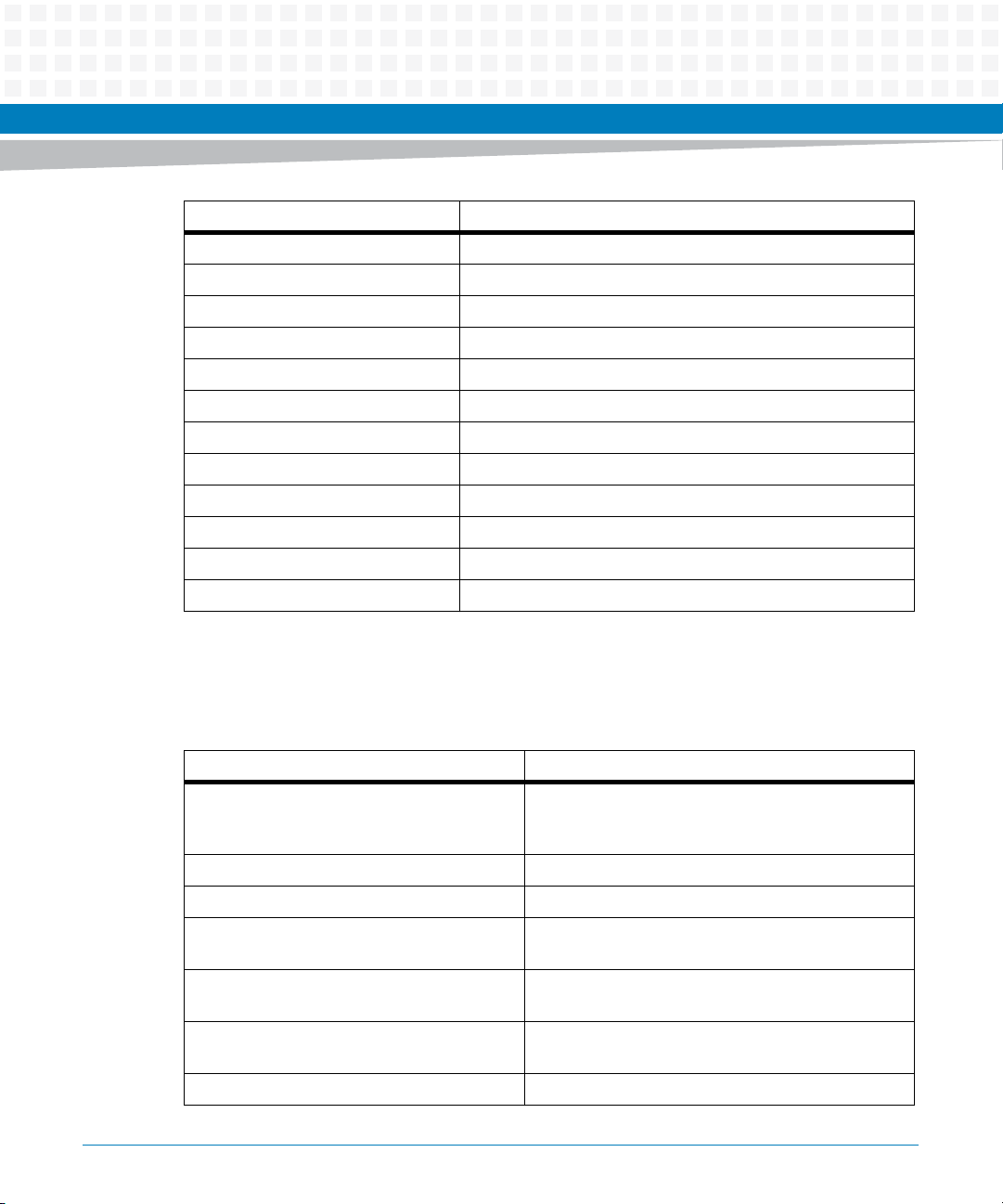
About this Manual
Abbreviation Definition
PICMG PCI Industrial Computer Manufacturers Group
RDR Resource Data Records
RMCP Remote Management Control Protocol
RoHS Restriction of the use of Certain Hazardous Substances
RTM Rear Transition Module
SAF Software Availability Forum
SDRAM Synchronous Dynamic Random Access Memory
SELV Safety Extra Low Voltages
ShM Shelf Manager
ShMC Shelf Management Controller
TPE Twisted Pair Ethernet
UL Underwriters Laboratory Inc.
Conventions
The following table describes the conventions used throughout this manual.
Notation Description
0x00000000 Typical notation for hexadecimal numbers (digits are
0b0000 Same for binary numbers (digits are 0 and 1)
bold Used to emphasize a word
Screen Used for on-screen output and code related elements
Courier + Bold Used to characterize user input and to separate it
Reference Used for references and for table and figure
File > Exit Notation for selecting a submenu
0 through F), for example used for addresses and
offsets
or commands in body text
from system output
descriptions
ATCA-MF106 Installation and Use (6806800M62B)
13
Page 14
About this Manual
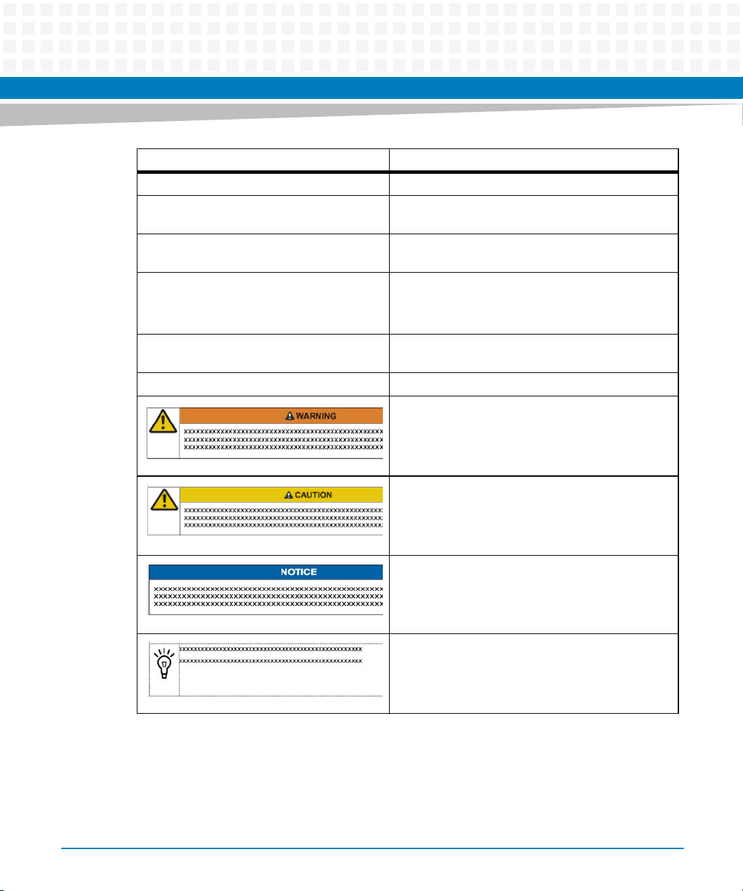
Notation Description
<text> Notation for variables and keys
[text] Notation for software buttons to click on the screen
... Repeated item for example node 1, node 2, ..., node
About this Manual
and parameter description
12
.
.
.
.. Ranges, for example: 0..4 means one of the integers
| Logical OR
Omission of information from example/command
that is not necessary at the time being
0,1,2,3, and 4 (used in registers)
Indicates a hazardous situation which, if not avoided,
could result in death or serious injury
Indicates a hazardous situation which, if not avoided,
may result in minor or moderate injury
Indicates a property damage message
No danger encountered. Pay attention to important
information
14
ATCA-MF106 Installation and Use (6806800M62B)
Page 15
Summary of Changes
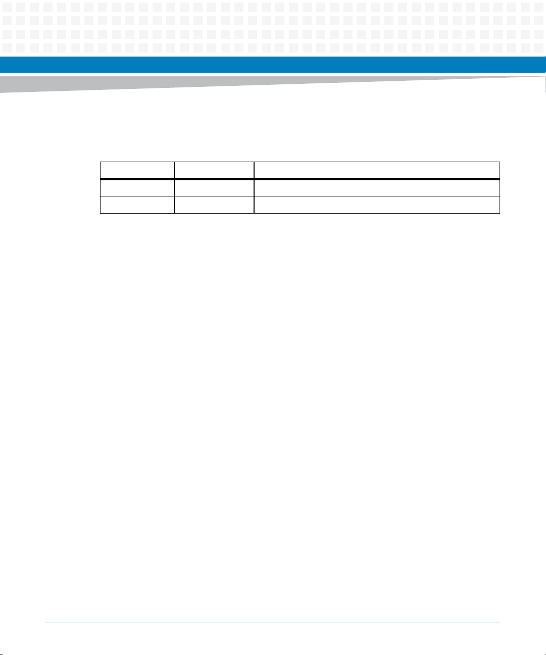
Order No. Date Description
6806800M62A July 2011 Initial version
6806800M62B September 2014 Re-branded to Artesyn template.
About this Manual
ATCA-MF106 Installation and Use (6806800M62B)
15
Page 16

About this Manual
About this Manual
16
ATCA-MF106 Installation and Use (6806800M62B)
Page 17

Safety Notes
This section provides warnings that precede potentially dangerous procedures throughout
this manual. Instructions contained in the warnings must be followed during all phases of
operation, service, and repair of this equipment. You should also employ all other safety
precautions necessary for the operation of the equipment in your operating environment.
Failure to comply with these precautions or with specific warnings elsewhere in this manual
could result in personal injury or damage to the equipment.
Artesyn Embedded Technologies intends to provide all necessary information to install and
handle the product in this manual. Because of the complexity of this product and its various
uses, we do not guarantee that the given information is complete. If you need additional
information, ask your Artesyn representative.
The product has been designed to meet the standard industrial safety requirements. It must
not be used except in its specific area of office telecommunication industry and industrial
control.
Only personnel trained by Artesyn or persons qualified in electronics or electrical engineering
are authorized to install, remove or maintain the product.
The information given in this manual is meant to complete the knowledge of a specialist and
must not be used as replacement for qualified personnel.
Keep away from live circuits inside the equipment. Operating personnel must not remove
equipment covers. Only factory authorized service personnel or other qualified service
personnel may remove equipment covers for internal subassembly or component replacement
or any internal adjustment.
Do not install substitute parts or perform any unauthorized modification of the equipment or
the warranty may be voided. Contact your local Artesyn representative for service and repair
to make sure that all safety features are maintained.
EMC
This equipment has been tested and found to comply with the limits for a Class A digital device,
pursuant to Part 15 of the FCC Rules. These limits are designed to provide reasonable
protection against harmful interference when the equipment is operated in a commercial
environment. This equipment generates, uses, and can radiate radio frequency energy and, if
not installed and used in accordance with the instruction manual, may cause harmful
interference to radio communications.
ATCA-MF106 Installation and Use (6806800M62B)
17
Page 18

Safety Notes
Operation of this equipment in a residential area is likely to cause harmful interference in which
case the user will be required to correct the interference at his own expense. Changes or
modifications not expressly approved by Artesyn could void the user's authority to operate the
equipment. Board products are tested in a representative system to show compliance with the
above mentioned requirements. A proper installation in a compliant system will maintain the
required performance. Use only shielded cables when connecting peripherals to assure that
appropriate radio frequency emissions compliance is maintained.
Installation
Before installing the board make sure the requirements listed in section "Board Exchange" are
met.
Restricted access area - This board is only to be installed in a restricted access area.
Data Loss
Removing the board with the blue LED still blinking causes data loss.
Wait until the blue LED is permanently illuminated, before removing the board.
Damage of Circuits
Electrostatic discharge and incorrect board installation and removal can damage circuits or
shorten their life.
Before touching the board or electronic components, make sure that you are working in an
ESD-safe environment or wear ESD wrist straps.
Board Malfunctioning
Incorrect board installation and removal can result in board malfunctioning.
Make sure that the board is connected to the system backplane via all assembled connectors
and that power is available on all zone 1 power pins.
Damage of the Product
Incorrect installation of the product can cause damage of the product,
Only use handles when installing/removing the product to avoid damage/deformation to the
face plate and/or PCB.
18
ATCA-MF106 Installation and Use (6806800M62B)
Page 19

Damage of the Product and Additional Devices and Modules
Incorrect installation or removal of additional devices or modules may damage the product or
the additional devices or modules.
Before installing or removing additional devices or modules, read the respective
documentation.
Operation
Board Damage
Board surface
High humidity and condensation on the board surface causes short circuits.
Do not operate the board outside the specified environmental limits. Make sure the board is
completely dry and there is no moisture on any surface before applying power.
Safety Notes
Board Overheating and Board Damage
Operating the board without forced air cooling may lead to board overheating and thus board
damage.
Injuries or Short Circuits
Board or power supply
In case the ORing diodes of the board fail, the board may trigger a short circuit between input
line A and input line B so that line A remains powered even if it is disconnected from the power
supply circuit (and vice versa).
To avoid damage or injuries, always check that there is no more voltage on the line that has
been disconnected before continuing your work.
Hot Swap
Installing the board into or removing it from a powered system not supporting hot swap or
high availability causes board damage and data loss. Therefore, only install it in or remove it
from a powered system if the system itself supports hot swap or high availability and if the
system documentation explicitly includes guidelines.
ATCA-MF106 Installation and Use (6806800M62B)
19
Page 20

Safety Notes
RJ-45 Connectors
The RJ-45 connectors on the face plate must only be used for twisted-pair Ethernet (TPE)
connections. Connecting a telephone to such a connector may destroy your telephone as well
as your board. Therefore:
Clearly mark TPE connectors near your working area as network connectors.
Only connect TPE bushing of the system to safety extra low voltage (SELV) circuits.
Make sure that the length of the electric cable connected to a TPE bushing does not
exceed 100 m.
If you have further questions, ask your system administrator.
Replacement/Expansion
Only replace or expand components or system parts with those recommended by Artesyn
Embedded Technologies. Otherwise, you are fully responsible for the impact on EMC or any
possible malfunction of the product.
Check the total power consumption of all components installed (see the technical
specification of the respective components). Ensure that any individual output current of any
source stays within its acceptable limits (see the technical specification of the respective
source).
Environment
Always dispose of used products according to your country’s legislation and manufacturer’s
instructions.
20
ATCA-MF106 Installation and Use (6806800M62B)
Page 21

Sicherheitshinweise
Dieses Kapitel enthält Hinweise, die potentiell gefährlichen Prozeduren innerhalb dieses
Handbuchs vorangestellt sind. Beachten Sie unbedingt in allen Phasen des Betriebs, der
Wartung und der Reparatur des Systems die Anweisungen, die diesen Hinweisen enthalten
sind. Sie sollten außerdem alle anderen Vorsichtsmaßnahmen treffen, die für den Betrieb des
Produktes innerhalb Ihrer Betriebsumgebung notwendig sind. Wenn Sie diese
Vorsichtsmaßnahmen oder Sicherheitshinweise, die an anderer Stelle dieses Handbuchs
enthalten sind, nicht beachten, kann das Verletzungen oder Schäden am Produkt zur Folge
haben.
Artesyn Embedded Technologies ist darauf bedacht, alle notwendigen Informationen zum
Einbau und zum Umgang mit dem Produkt in diesem Handbuch bereit zu stellen. Da es sich
jedoch um ein komplexes Produkt mit vielfältigen Einsatzmöglichkeiten handelt, können wir
die Vollständigkeit der im Handbuch enthaltenen Informationen nicht garantieren. Falls Sie
weitere Informationen benötigen sollten, wenden Sie sich bitte an die für Sie zuständige
Geschäftsstelle von Artesyn.
Das System erfüllt die für die Industrie geforderten Sicherheitsvorschriften und darf
ausschließlich für Anwendungen in der Telekommunikationsindustrie und im Zusammenhang
mit Industriesteuerungen verwendet werden.
Einbau, Wartung und Betrieb dürfen nur von durch Artesyn ausgebildetem oder im Bereich
Elektronik oder Elektrotechnik qualifiziertem Personal durchgeführt werden. Die in diesem
Handbuch enthaltenen Informationen dienen ausschließlich dazu, das Wissen von
Fachpersonal zu ergänzen, können dieses jedoch nicht ersetzen.
Halten Sie sich von stromführenden Leitungen innerhalb des Produktes fern. Entfernen Sie auf
keinen Fall Abdeckungen am Produkt. Nur werksseitig zugelassenes Wartungspersonal oder
anderweitig qualifiziertes Wartungspersonal darf Abdeckungen entfernen, um Komponenten
zu ersetzen oder andere Anpassungen vorzunehmen.
Installieren Sie keine Ersatzteile oder führen Sie keine unerlaubten Veränderungen am Produkt
durch, sonst verfällt die Garantie. Wenden Sie sich für Wartung oder Reparatur bitte an die für
Sie zuständige Geschäftsstelle von Artesyn. So stellen Sie sicher, dass alle
sicherheitsrelevanten Aspekte beachtet werden.
ATCA-MF106 Installation and Use (6806800M62B)
21
Page 22

Sicherheitshinweise
EMV
Das Produkt wurde in einem Artesyn Standardsystem getestet. Es erfüllt die für digitale Geräte
der Klasse A gültigen Grenzwerte in einem solchen System gemäß den FCC-Richtlinien
Abschnitt 15 bzw. EN 55022 Klasse A. Diese Grenzwerte sollen einen angemessenen Schutz
vor Störstrahlung beim Betrieb des Produktes in Gewerbe- sowie Industriegebieten
gewährleisten.
Das Produkt arbeitet im Hochfrequenzbereich und erzeugt Störstrahlung. Bei
unsachgemäßem Einbau und anderem als in diesem Handbuch beschriebenen Betrieb können
Störungen im Hochfrequenzbereich auftreten.
Wird das Produkt in einem Wohngebiet betrieben, so kann dies mit großer Wahrscheinlichkeit
zu starken Störungen führen, welche dann auf Kosten des Produktanwenders beseitigt werden
müssen. Änderungen oder Modifikationen am Produkt, welche ohne ausdrückliche
Genehmigung von Artesyn Embedded Technologies durchgeführt werden, können dazu
führen, dass der Anwender die Genehmigung zum Betrieb des Produktes verliert.
Boardprodukte werden in einem repräsentativen System getestet, um zu zeigen, dass das
Board den oben aufgeführten EMV-Richtlinien entspricht. Eine ordnungsgemäße Installation
in einem System, welches die EMV-Richtlinien erfüllt, stellt sicher, dass das Produkt gemäß den
EMV-Richtlinien betrieben wird. Verwenden Sie nur abgeschirmte Kabel zum Anschluss von
Zusatzmodulen. So ist sichergestellt, dass sich die Aussendung von Hochfrequenzstrahlung im
Rahmen der erlaubten Grenzwerte bewegt.
Warnung! Dies ist eine Einrichtung der Klasse A. Diese Einrichtung kann im Wohnbereich
Funkstörungen verursachen. In diesem Fall kann vom Betreiber verlangt werden,
angemessene Maßnahmen durchzuführen.
Board Installation
Bevor Sie das Board in einem System installieren, überprüfen Sie, ob die im Kapitel "Board
Exchange" aufgeführten Anforderungen erfüllt werden.
Bereich mit eingeschränktem Zugang - Installieren Sie das Board in ein System nur in Bereichen
mit eingeschränktem Zugang.
22
ATCA-MF106 Installation and Use (6806800M62B)
Page 23

Datenverlust
Ziehen Sie das Board im laufenden Betrieb heraus, obwohl die Hot-Swap LED noch nicht
leuchtet, führt das zu Datenverlust.
Warten Sie deshalb bis die Hot-Swap LED blau leuchtet, bevor Sie das Board herausziehen.
Beschädigung von Schaltkreisen
Elektrostatische Entladung und unsachgemäßer Ein- und Ausbau des Produktes kann
Schaltkreise beschädigen oder ihre Lebensdauer verkürzen.
Bevor Sie das Produkt oder elektronische Komponenten berühren, vergewissern Sie sich, dass
Sie in einem ESD-geschützten Bereich arbeiten.
Fehlfunktion des Produktes
Fehlerhafter Ein- und Ausbau des Produktes kann zur Beschädigung des Produktes führen.
Stellen Sie deshalb sicher, dass das Produkt mit allen Steckern mit der Systembackplane
verbunden ist und über alle Zone-1-Anschlüsse mit Spannung versorgt wird.
Sicherheitshinweise
Beschädigung des Produktes
Fehlerhafte Installation des Produktes kann zu einer Beschädigung des Produktes führen.
Verwenden Sie die Handles, um das Produkt zu installieren/deinstallieren. Auf diese Weise
vermeiden Sie, dass das Face Plate oder die Platine deformiert oder zerstört wird.
Beschädigung des Produktes und von Zusatzmodulen
Fehlerhafte Installation von Zusatzmodulen, kann zur Beschädigung des Produktes und der
Zusatzmodule führen.
Lesen Sie daher vor der Installation von Zusatzmodulen die zugehörige Dokumentation.
Betrieb
Beschädigung des Boards
Hohe Luftfeuchtigkeit und Kondensat auf der Oberfläche des Boards können zu Kurzschlüssen
führen.
Betreiben Sie das Board nur innerhalb der angegebenen Grenzwerte für die relative
Luftfeuchtigkeit und Temperatur. Stellen Sie vor dem Einschalten des Stroms sicher, dass sich
auf dem Board kein Kondensat befindet.
ATCA-MF106 Installation and Use (6806800M62B)
23
Page 24

Sicherheitshinweise
Überhitzung und Beschädigung des Boards
Betreiben Sie das Board ohne Zwangsbelüftung, kann das Board überhitzt und schließlich
beschädigt werden.
Bevor Sie das Board betreiben, müssen Sie sicher stellen, dass das Shelf über eine
Zwangskühlung verfügt.
Verletzungen oder Kurzschlüsse
Board oder Stromversorgung
Falls die ORing Dioden des Boards durchbrennen, kann das Board einen Kurzschluss zwischen
den Eingangsleitungen A und B verursachen. In diesem Fall ist Leitung A immer noch unter
Spannung, auch wenn sie vom Versorgungskreislauf getrennt ist (und umgekehrt).
Prüfen Sie deshalb immer, ob die Leitung spannungsfrei ist, bevor Sie Ihre Arbeit fortsetzen,
um Schäden oder Verletzungen zu vermeiden.
Hot Swap
Wenn Sie das Board im laufenden Betrieb in ein System, das weder Hot Swap noch High
Availability unterstützt, installieren bzw. herausziehen, wird das Board beschädigt und es
gehen Daten verloren. Installieren/entfernen Sie das Board nur im laufenden Betrieb, wenn das
System Hot Swap oder High-Availability unterstützt und wenn die Systembeschreibung dies
ausdrücklich erlaubt.
RJ-45 Stecker
Die RJ-45 Stecker auf der Frontblende dürfen nur für Twisted-Pair-Ethernet (TPE)Verbindungen verwendet werden. Beachten Sie, dass ein versehentliches Anschließen einer
Telefonleitung an einen solchen TPE Stecker sowohl das Telefon als auch das Board zerstören
kann. Beachten Sie deshalb die folgenden Hinweise:
Kennzeichnen Sie TPE-Anschlüsse in der Nähe Ihres Arbeitsplatzes deutlich als
Netzwerkanschlüsse.
Schließen Sie an TPE-Buchsen ausschließlich SELV-Kreise
(Sicherheitskleinspannungsstromkreise) an.
Die Länge des mit dem Board verbundenen Twisted-Pair Ethernet-Kabels darf 100 m nicht
überschreiten.
Falls Sie Fragen haben, wenden Sie sich bitte an Ihren Systemadministrator.
24
ATCA-MF106 Installation and Use (6806800M62B)
Page 25

Austausch/Erweiterung
Verwenden Sie bei Austausch oder Erweiterung nur von Artesyn Embedded Technologies
empfohlene Komponenten und Systemteile. Andernfalls sind Sie für mögliche Auswirkungen
auf EMV oder Fehlfunktionen des Produktes voll verantwortlich.
Überprüfen Sie die gesamte aufgenomme Leistung aller eingebauten Komponenten (siehe die
technischen Daten der entsprechenden Komponente). Stellen Sie sicher, dass die
Stromaufnahme jedes Verbrauchers innerhalb der zulässigen Grenzwerte liegt (siehe die
technischen Daten des entsprechenden Verbrauchers).
Umweltschutz
Entsorgen Sie alte Batterien und/oder Produkte stets gemäß der in Ihrem Land gültigen
Gesetzgebung und den Empfehlungen des Herstellers.
Sicherheitshinweise
ATCA-MF106 Installation and Use (6806800M62B)
25
Page 26

Sicherheitshinweise
26
ATCA-MF106 Installation and Use (6806800M62B)
Page 27

Introduction
1.1 Overview
The Artesyn Embedded Technologies ATCA-MF106 is a shelf manager & hub board intended to
be used in AdvancedTCA systems. The ATCA-MF106 combines a shelf management controller
and a GBE hub in a single FRU.
This document details the hardware features and exchange procedures of the ATCA-MF106.
For a description of the AdvancedTCA shelf management interface and a detailed software
description, see the System Management Interface Based on HPI-B (Centellis CO 31kX/4100/2000)
User’s Guide and the AdvancedTCA Specification (PICMG 3.0).
The ATCA-MF106 plugs into a dedicated shelf management slot of a Centellis 2000
AdvancedTCA system. The board provides management for up to two AdvancedTCA front
blades as well as for fans and user cards that can be present in an AdvancedTCA system. In a
redundant configuration the ATCA-MF106 are used as redundant shelf managers.
Chapter 1
The hub of the ATCA-MF106 provides ports to the shelf managers and the AdvancedTCA
blades and an uplink on the face plate.
For more information on using the ATCA-MF106 in an AdvancedTCA system, e.g., on network
configuration, see the Centellis 2000 Shelf-DC Installation and Use manual.
The shelf manager is a main component of the shelf management system. It is compliant to the
shelf management functions as described in the AdvancedTCA Specification (PICMG 3.0). The
shelf management system is designed to be used in AdvancedTCA systems and its purpose is
to ensure proper operation of AdvancedTCA blades and other system components like fans
and rear transition modules (RTMs).
The shelf manager reports anomalies and errors and takes corrective actions if required (for
example, increase the speed of the fans). It can display the alarm states via LEDs of the
AdvancedTCA system.
The communication between the system manager and the shelf manager can be based on:
Remote hardware platform interface (HPI)
Remote management control protocol (RMCP)
Simple Network Management Protocol (SNMP)
For debugging and maintenance purposes, you can also access the shelf manager via a
command line interface (CLI).
ATCA-MF106 Installation and Use (6806800M62B)
27
Page 28
Introduction
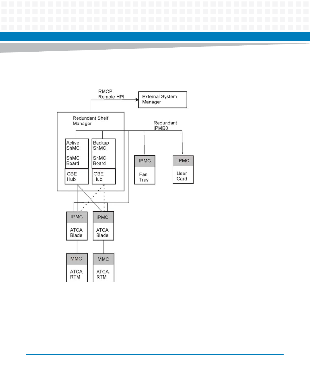
The following figure shows the shelf management architecture.
Figure 1-1 Shelf Management Architecture
28
ATCA-MF106 Installation and Use (6806800M62B)
Page 29

Introduction
The shelf management system consists of several major components:
Distributed intelligent management controllers which manage and monitor the operation
and environment conditions of the FRUs in the shelf.
Shelf manager which implements a system management interface and contains a shelf
management controller (ShMC) through which it communicates to other intelligent
platform management controllers (IPMCs).
Intelligent platform management interface (IPMI) infrastructure that provides
communication, management, and control paths among the distributed controllers and
to the shelf manager. The IPMI infrastructure is fully compliant to the IPMI V.1.5 and
AdvancedTCA specifications.
The shelf manager consists of hardware (payload and shelf management controller) and
software.
For a description of the software, see the System Management Interface Based on HPI-B (Centellis
CO 31kX/4100/2000) User’s Guide.
ATCA-MF106 Installation and Use (6806800M62B)
29
Page 30
Introduction
1.2 Hardware
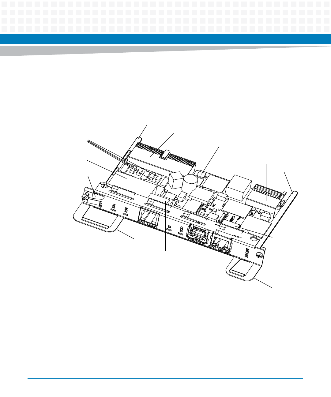
The following figure gives an overview about the main parts of the board.
Figure 1-2 Overview
Fuses
Alignment Pin
Backplane Connector
Temperature Sensor
DC/DC Converter
Handle Switch Activator
Extraction Handle
Backplane Connector
Alignment Pin
Ethernet
Connector
Ethernet Connector
Extraction Handle
30
ATCA-MF106 Installation and Use (6806800M62B)
Page 31
1.2.1 Shelf Manager Hardware
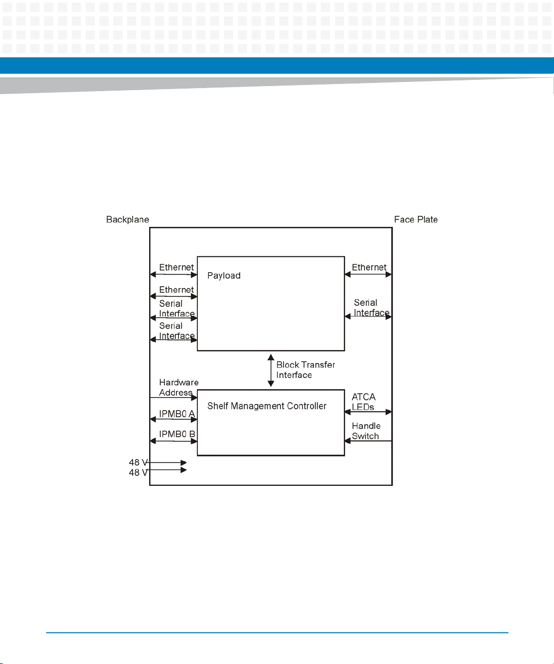
Artesyn Embedded Technologies's implementation of the shelf manager is based on the
configuration #2, PICMG 3.0 specification, where the shelf manager is divided in the shelf
management controller and the payload hardware.
Figure 1-3 Shelf Manager Hardware
Introduction
The payload hardware provides the following features:
CPU with the shelf management software
Network connection to the system manager
Redundancy interface to a second shelf manager instance
Block transfer interface to the ShMC
Hardware platform interface (HPI) to the system manager
ATCA-MF106 Installation and Use (6806800M62B)
31
Page 32
Introduction
MicroSD memory interface
Serial EEPROM for environment variable storage
Redundant Boot flash device
The ShMC consists of two coupled microcontrollers:
IPMC Master Controller (IMC) based on an Atmega 128
IPMC Slave Controller (ISC), based on an Atmega 8.
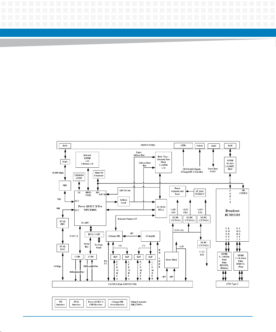
The following block diagram outlines the major hardware components.
Figure 1-4 Block Diagram
32
ATCA-MF106 Installation and Use (6806800M62B)
Page 33

Introduction
The ATCA-MF106 consists of the dual ATmega IPMC as a front-end to the IPMB in the shelf, and
the "Service Processor" based on a PowerQUICC, which provides the management functions.
The ATCA-MF106 is designed for redundant operation in AdvancedTCA shelves. Usually, two
ATCA-MF106 shelf managers are deployed in one shelf, one of which takes the role of active
ATCA-MF106, the other acting as standby ready to take over in case of failure of the active one.
Redundant channels for heartbeating and checkpointing between the two ATCA-MF106 are
provided.
The ATCA-MF106 shelf manager supports the following components:
Freescale’s MPC8306S PowerQUICC processor with embedded PowerPC core
ATmega128L (master) and ATmega8L (slave) micro-controllers from Atmel
64 MB SDRAM memory
64 MB redundant boot and user flash
Dual redundant IPMB interface
Two 10/100 Mbps Ethernet interfaces to the rear connector and one 10/100 Mbps
Ethernet port to the face plate
Power brick supplying 3.5 A at 3.4 V (conventionally referred as 3.3 V)
Two serial (differential) ports to the rear connector
Local temperature sensor
Block transfer interface through the FPGA
LED indicators
2
I
C interface, analog inputs and digital I/O from ATmegas to support shelf specific
functions
Rear connector to the backplane (2 mm connector)
MicroSD memory module
ATCA-MF106 Installation and Use (6806800M62B)
33
Page 34

Introduction
1.2.2 Hub Hardware
The ATCA-MF106 hub supports the following interfaces:
One 10/100/1000 Mbps Ethernet uplink on the face plate
Two 10/100 Mbps Ethernet ports, one to each shelf manager, routed via the backplane
Two 10/100/1000 Mbps Ethernet ports, one to each blade’s base interface, routed via the
backplane
1.3 Shelf Management Software
The shelf management software provides the following features:
Hardware platform interface (HPI) based shelf management includes:
– FRU inventory information management
–Hot swap
– E-keying
– System event log
– Power management
– Cooling management
For more information on these topics, see the System Management Interface Based on HPI-B
(Centellis CO 31kX/4100/2000) User’s Guide and the AdvancedTCA Specification (PICMG 3.0).
Remote access via:
– Remote HPI
– RMCP
– SNMP
Software upgrade management:
– File transfer
– Flash procedure
34
ATCA-MF106 Installation and Use (6806800M62B)
Page 35

High-availability management includes:
– Redundancy management
– Network management
– Aliveness monitoring
1.3.1 HPI Based Shelf Management
The shelf management is based on an open industry standard, called Hardware Platform
Interface (HPI). HPI is provided by the service availability forum (SAF).
HPI provides a platform independent interface to platform specific services.
A manageable shelf component is identified by the HPI as a unique resource in the system. Each
resource is modeled as a collection of resource data records (RDR) which contain information
about the controls, sensors, inventory data, and watchdog timers. Via this data the user can
monitor and control the state of the system.
Introduction
The following data is used by the shelf management:
Shelf FRU information
The shelf FRU information defines the shelf topology, for example type and number of
slots, backplane topology.
FRU inventory data
The FRU inventory data consists of the board info area, the product info area, and the multi
record area.
– Board info area
It consists of the manufacturer name, manufacturing date, the board product name,
the board serial number, and the board part number.
– Product info area
It consists of the manufacturer name, manufacturing date, the product name, the
product serial number, and the product part number.
– Multi record area
It describes AdvancedTCA inventory data like point-to-point connectivity and the user
info area.
Hot swap states
ATCA-MF106 Installation and Use (6806800M62B)
35
Page 36

Introduction
E-Keying
System event log
A resource can implement the full or the simplified hot swap model. The supported full hot
swap states are:
–Not present
– Insertion pending
– Active/healthy
– Extraction pending
–Inactive
E-keying prevents damage to AdvancedTCA blades, verifies fabric compatibility and
prevents mis-operation.
Each event generates an entry in the system event log maintained by the shelf manager.
Power management
The shelf manager controls the power budget of the shelf.
Cooling management
The shelf manager controls the cooling of the shelf. The cooling management is based on
the IPMI infrastructure of the shelf and the temperature sensor event generation.
1.3.2 Remote Access
Remote access can be executed via remote HPI and RMCP.
1.3.2.1 Remote HPI
ATCA-MF106 provides HPI based utilities for remote accessing and remote management. HPI
based utilities allows to retrieve, monitor and modify the attributes of the system. 'hpiipmi' is
one of such utility in which the IPMI commands can be sent to a particular HPI resource.
Following are the sample 'hpiipmi' remote accessing commands:
Send GetDeviceId command (Lun=0, Netfn=6, Cmd=1) to resource 49 on domain 1:
hpiipmi -d 1 -r 49 0 6 1
Send GetSelInfo command (Lun=0, Netfn=a, Cmd=40) to resource 30 on domain 1:
36
ATCA-MF106 Installation and Use (6806800M62B)
Page 37

hpiipmi -d 1 -r 30 0 a 40
Send Set boot options command (Lun=0, Netfn=0, cmd=8) to resource 184 on domain 1:
hpiipmi -d 1 -r 184 0 0 8 60 0 2
1.3.2.2 RMCP
RMCP is basically an IP encapsulation of IPMI messages. By using system management
software with support for RMCP, you can remotely monitor and manage the shelf.
Following is the sample IPMITOOL remote accessing command:
ipmitool -H 172.17.0.8 -U Administrator -P Administrator -t
0x9c sensor
It is recommended that the RMCP interface shall be used only for the Monitoring purposes.
Introduction
Below RMCP server is available for ATCA-MF106:
Standard RMCP server included in the HPI daemon running on the active ATCA-MF106
In order to access the RMCP server you have to specify on the RMCP client side:
IP address
Session parameters
The standard RMCP server is running inside the HPI daemon. You can access it via port 623. The
default configuration shown below is an extract of the configuration file /etc/bbs-
hpib/bbs-hpib.conf.
RmcpEnable = "true"
RmcpPort = "623"
RmcpMaxConnection = "10"
RmcpConnectionTimeout = "15000"
RmcpPefAlerting= "true"
RmcpPerMsgAuth = "true"
ATCA-MF106 Installation and Use (6806800M62B)
37
Page 38

Introduction
RmcpPrivLimit = "admin"
RmcpAllowedAuthsCallback = "none md2 md5 straight"
RmcpAllowedAuthsUser = "none md2 md5 straight"
RmcpAllowedAuthsOperator = "none md2 md5 straight"
RmcpAllowedAuthsAdmin = "none md2 md5 straight"
RmcpGuid = "01 02 03 04 05 06 07 08 09 10 11 12 13 14 15 16"
RmcpUser2 = "'' '' admin 64 none md2 md5 straight"
RmcpUser3 = "user user admin 64 none"
RmcpUser4 = "kanne kanne admin 64 none md2 md5 straight"
RmcpUser5 = "hf hf admin 64 none md2 md5 straight"
RmcpUser6 = "Administrator Administrator admin 64 none md2 md5 straight"
1.3.3 Software Upgrade Management
The software upgrade module is responsible for the following services:
Upgrade of payload software on the shelf manager
Upgrade of IPMI firmware of intelligent FRUs in the shelf
Universal upload/download of regular files from/to the shelf manager
Before upgrading a particular software component, the new image has to be transferred to the
shelf manager. The soft ware upgrade module requires an external server where the new image
is located. The server location is specified by the URL. The file transfer uses FTP and requires an
external FTP server.
The software upgrade management interface additionally supports a universal upload and
download mechanism. This enables the transfer of any regular files to and from the shelf
manager.
1.3.4 High-Availability Management
High availability management includes redundancy and network management.
1.3.4.1 Redundancy
The redundancy is provided by the shelf managers. The implemented redundancy mechanism
is cold standby. In case of a failure, a failover is performed from the active to the standby shelf
manager. This takes two seconds.
38
ATCA-MF106 Installation and Use (6806800M62B)
Page 39

1.3.4.2 Network Management
The main tasks of the network management are the assignments of backplane and out-of-band
IP addresses by the shelf manager and the switchover of IP addresses from the active to the
backup device.
Introduction
ATCA-MF106 Installation and Use (6806800M62B)
39
Page 40

Introduction
1.4 Standard Compliances
The ATCA-MF106, when installed in a compliant chassis, meets the following standards:
Table 1-1 Standard Compliances
Standard Description
UL 60950-1
EN 60950-1
IEC 60950-1
CAN/CSA C22.2 No 60950-1
CISPR 22
CISPR 24
EN 55022
EN 55024
FCC Part 15
Industry Canada ICES-003
VCCI Japan
AS/NZS CISPR 22
EN 300 386
NEBS Standard GR-1089 CORE
ANSI/IPC-A610 Rev.C Class 2
ANSI/IPC-7711
ANSI/IPC-7721
ANSI-J-001...003
NEBS Standard GR-63-CORE
ETSI EN 300 019 series
PICMG 3.0 R3.0 Defines mechanics, blade dimensions, power distribution,
Legal safety requirements
Legal EMC requirements on system level (predefined
Artesyn Embedded Technologies system)
Manufacturing requirements
Environmental requirements
power and data connectors, and system management
40
The product has been designed to meet the directive on the restriction of the use of
certain hazardous substances in electrical and electronic equipment (RoHS) Directive
2002/95/EC.
The ATCA-MF106 can be operated from -5 ºC up to +55 ºC without forced cooling.
ATCA-MF106 Installation and Use (6806800M62B)
Page 41
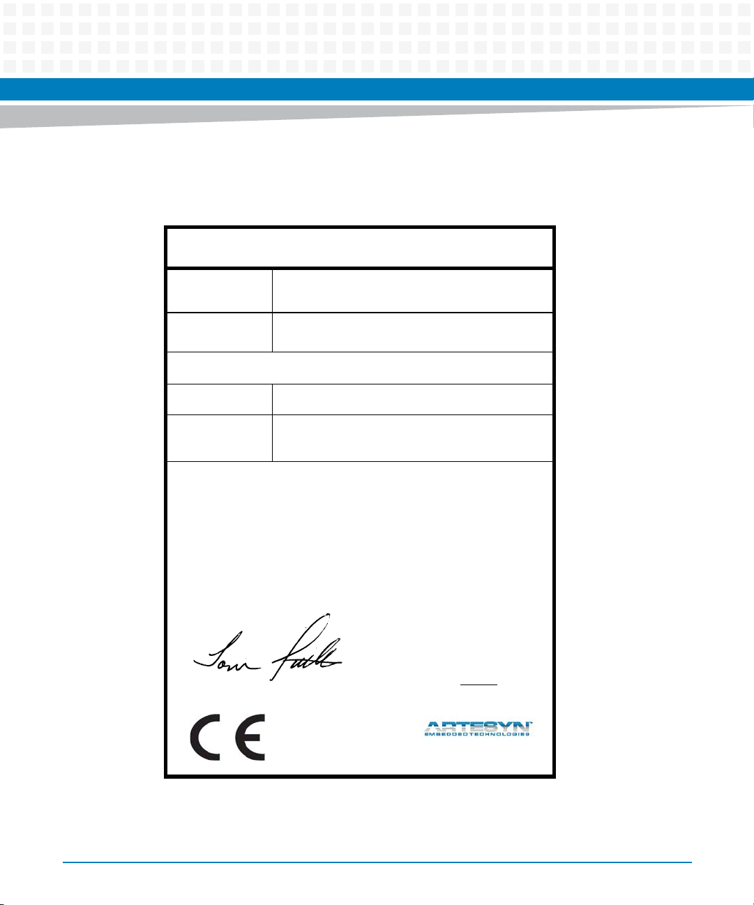
The following figure contains the Declaration of Conformity for ATCA-MF106.
Figure 1-5 Declaration of Conformity
E
C Declaration of Conformity
According to EN 17050-1:2004
Introduction
Manufacturer’s Name:
Manufacturer’s Address:
Declares that the following product, in accordance with the requirements of 2004/108/EC, 2006/95/EC, 2011/65/
EU and their amending directives,
Product:
Model Name/Number:
has been designed and manufactured to the following specifications:
EN55022: 2006 + (A1: 2007) ClassA
EN55024: 1998 + (A1: 2001 + A2: 2003)
EN300 386 V1.5.1: 2010
IEC 60950-1 Ed 2: 2005
2011/65/EU RoHS Directive
As manufacturer we hereby declare that the product named above has been designed to comply with the relevant sections of the above referenced specifications. This product complies with the essential health and safety
requirements of the above specified directives. We have an internal production control system that ensures
compliance between the manufactured products and the technical documentation.
___________________________________________________ ___
Tom Tuttle, Manager, Product Testing Services Date (MM/DD/YYYY)
Artesyn Embedded Technologies
Embedded Computing
Zhongshan General Carton Box Factory Co. Ltd. No 62, Qi
Guan Road West, Shiqi District, 528400 Zhongshan City
Guangdong, PRC
MF106—SHMM Module with Integrated Base Switch
C2000-MF106-C01, CENT-2000-MF106
09/11/2014______
ATCA-MF106 Installation and Use (6806800M62B)
41
Page 42

Introduction
1.5 Ordering Information
The table below shows the board's ordering information.
For further details please contact your local Artesyn Embedded Technologies representative.
Table 1-2 Ordering Information
Order No. Name Description
CENT-2000-MF106 MF106 shelf manager & hub board
assembly
Shelf manager & hub board used in
Centellis 2000 systems
42
ATCA-MF106 Installation and Use (6806800M62B)
Page 43
ATCA-MF106 Hardware
2.1 Overview
The ATCA-MF106 is compliant to PICMG 3.0 R3.0 (AdvancedTCA). The shelf manager and hub
board is equipped with two backplane connectors.
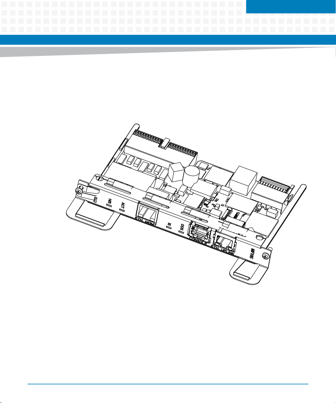
Figure 2-1 Hardware
Chapter 2
To prevent connector damage the alignment pin offers a guide rail to the slot and a coding
mechanism to ensure the installation of the board in the matching slot.
The hardware consists of:
Payload hardware section with:
– Service Processor
– Ethernet interfaces to the backplane and to the face plate
ATCA-MF106 Installation and Use (6806800M62B)
43
Page 44

ATCA-MF106 Hardware
– Redundant connection between two shelf managers via backplane
– Block transfer interface to the ShMC
Shelf management controller section with:
– IPMB0-A and IPMB0-B interface to the backplane
– Handle switch and status LED interface to the face plate
Support logic for testing and debugging as well as local and remote programming of all
programmable devices on the board.
Power supply
5-port Gigabit Ethernet hub
2.2 Payload Hardware
The payload hardware of the shelf manager is always powered when power supply is present.
During power-on, the ShMC keeps the payload in a reset state.
The following interfaces are available:
Three Ethernet interfaces
Two redundancy interfaces (serial)
Block transfer interface
2.2.1 Ethernet Interfaces
The shelf management part of the board has three Ethernet ports which are available
concurrently.
One 10/100 BaseT out-of-band interface is accessible via a RJ-45 connector at the face plate
marked with "MGMT ETH". Link and activity status LEDs are integrated into the connector.
Two 10/100 BaseT interfaces are connected to the backplane connector at the pins Eth1-Hub
Tx/Rx and Eth2-Hub Tx/Rx. They route the base interface to the hubs of both the ATCA-MF106
which in turn are connected to the node blades in dual star topology. They are compliant with
the PICMG 3.0 R3.0 specification (AdvancedTCA) for the base interface.
44
ATCA-MF106 Installation and Use (6806800M62B)
Page 45

2.2.2 Redundancy Interfaces
The ATCA-MF106 uses a private, redundant, high-speed, full duplex serial connection for
heartbeating and data replication between the two shelf managers.
The redundancy interface is routed to the backplane via differential line LVDS transceivers. The
physical interface of both channels is compliant with the PICMG 3.0 R3.0 (AdvancedTCA)
specification for the update interface.
Each of the serial inputs of the redundancy interface triggers an interrupt to the PowerQUICC
when the other shelf manager:
initiates a break-in condition on the serial line
experiences a power failure
goes in the reset state
is extracted
ATCA-MF106 Hardware
2.2.3 Block Transfer Interface
The payload CPU is connected to the ShMC via a parallel interface with interrupt support called
block transfer interface, implemented in a FPGA.
The block transfer (BT) interface is compliant with IPMI specification v1.5.
2.3 Shelf Management Controller
The ShMC part is derived from Artesyn Embedded Technologies's IPMC building block and
consists of two coupled microcontrollers:
IPMC Master Controller (IMC) based on an Atmega 128
IPMC Slave Controller (ISC), based on an Atmega 8
2.3.1 IPMB0 Interface
IPMB0-A is connected to the I2C controller of the IMC, IPMB0-B to the I2C controller of the ISC
of the ShMC. Both microcontrollers have their own I2C controller and handle message
transmission and reception independently, including bus error handling and bus arbitration.
ATCA-MF106 Installation and Use (6806800M62B)
45
Page 46

ATCA-MF106 Hardware
Received messages sent from both the IMC and the ISC channels are collected by the IMC. The
IMC dispatches messages which have to be sent either to its own I
transmission.
2.3.2 IPMC Standard Functions
The standard functionality of the Artesyn Embedded Technologies IPMC is available on the
IPMC of the ATCA-MF106. For detailed information, see the ATCA-MF106: Control via IPMI
Programmer’s Reference.
2.4 Power Supply
The shelf manager is powered by dual redundant -48 VDC to -60 VDC (rated voltage) from the
backplane connector.
The power supply of the shelf manager is compliant with the requirements of the PICMG 3.0
R3.0 (AdvancedTCA) specification. Each of the four power connections is separately fused.
Fuse rating is 1 A.
An EMI filter at the power input ensures conducted emission levels below EN 55022 class B.
2
C interface or to the ISC for
2.4.1 Onboard and External Supply
The ATCA-MF106 has no provisions to switch off the power input. The board is powered
whenever the power is attached to the Centellis 2000 system (-40 VDC to -72 VDC).
An on-board DC/DC-converter supplies all onboard circuitry, and provides:
3.3 V power supply to external circuits with a consumption of no more than 4 W
3.4 V management power via the backplane pins
Output voltage is slightly above 3.3 V to compensate losses caused by ORing circuits, which
may be present at the external load.
The board satisfies the standby power limit of 10 W for AdvancedTCA FRUs, even when
supplying 4 W to external loads. Typical power consumption of the ATCA-MF106 board is 5 W.
46
ATCA-MF106 Installation and Use (6806800M62B)
Page 47

2.4.2 Power Supply Holdup
The ATCA-MF106 complies with the requirements for board level voltage transients as
described in chapter 4.1.4.3. of PICMG 3.0 (AdvancedTCA) specification.
It satisfies the requirement of uninterrupted operation during a power failure of 5 ms, while
supplying 4 W to external circuits.
ATCA-MF106 Hardware
ATCA-MF106 Installation and Use (6806800M62B)
47
Page 48
ATCA-MF106 Hardware
2.5 Gigabit Ethernet Hub
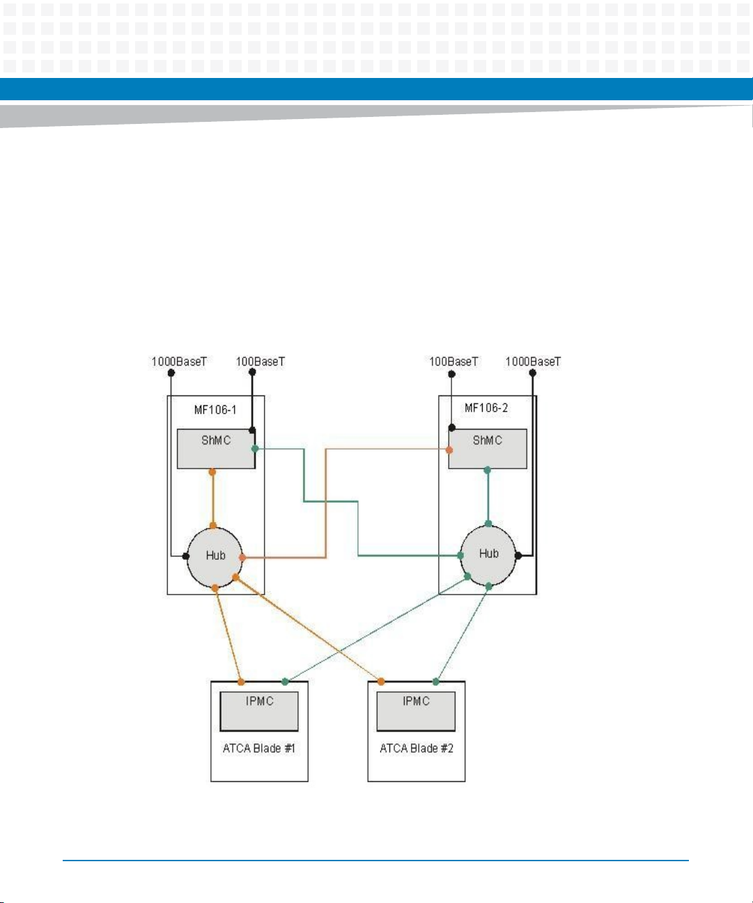
The hub of the ATCA-MF106 is a managed Layer 2 Gigabit Ethernet switch which provides the
following ports:
One 10/100/1000 Mbps Ethernet uplink on the face plate
Two 10/100 Mbps Ethernet ports, one to each shelf manager
Two 10/100/1000 Mbps Ethernet ports, one to each blade’s base interface
Figure 2-2 Base IP Network with GBE Hub
48
For more information refer also to the Centellis 2000 Shelf - DC Installation and Use manual.
ATCA-MF106 Installation and Use (6806800M62B)
Page 49

2.6 Frame Ground and ESD
Frame ground connection is provided by the backplane connector FrameGND.
The face plate mounting holes of the board are connected to frame ground.
An ESD strip according to the AdvancedTCA specification PICMG 3.0 R3.0 for rear transition
modules (RTMs) is provided at one edge of the PCB.
ATCA-MF106 Hardware
ATCA-MF106 Installation and Use (6806800M62B)
49
Page 50

ATCA-MF106 Hardware
50
ATCA-MF106 Installation and Use (6806800M62B)
Page 51
Controls, Indicators and Connectors
3.1 Face Plate
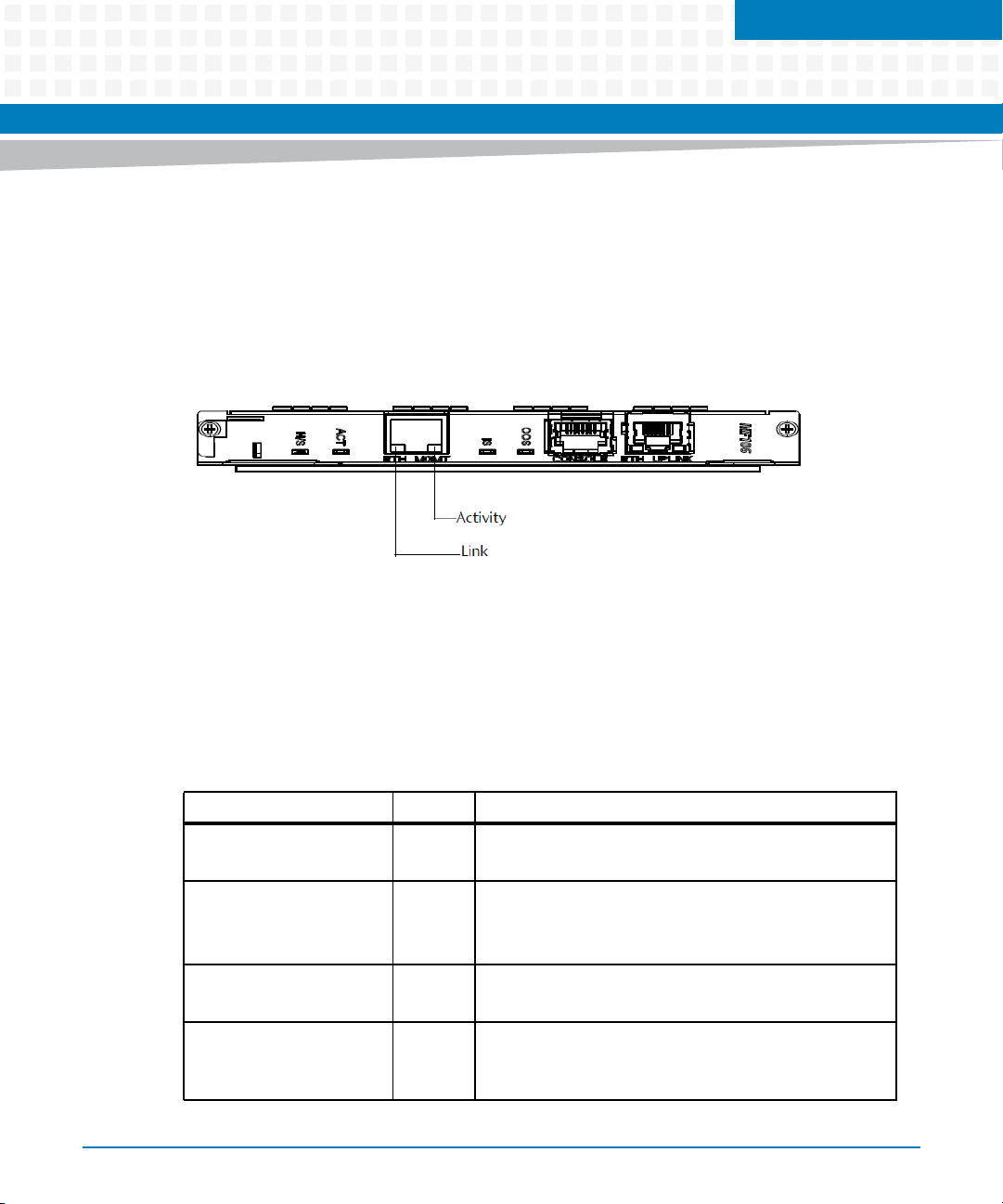
The following figure highlights the position of LEDs and connectors on the face plate of the
board. They are described in sections LEDs on page 51 and Ethernet Connectors on page 52 and
Console Connector.
Figure 3-1 Face Plate
Chapter 3
3.1.1 LEDs
The following LEDs can be found on the face plate of the board. OOS, OK and ACT are ATCA
LEDs and can be controlled via IPMI. For more information, see the ATCA-MF106: Control via IPMI
Programmer’s Reference manual.
Table 3-1 Face Plate LEDs
LED Color Description
OOS (failure) Red Red: The ATCA-MF106 is out-of-service.
IS (In Service) Green Green: The ATCA-MF106 is operating properly.
ACT (active) Amber Amber: The ATCA-MF106 is active.
H/S Blue Blue: The ATCA-MF106 is ready to be extracted.
Off: The ATCA-MF106 is working properly.
Off: Otherwise
Blinking: The board boots up.
Off: The ATCA-MF106 is in the standby mode.
Off: The ATCA-MF106 is not ready to be extracted. Do not
remove the board during this state.
ATCA-MF106 Installation and Use (6806800M62B)
51
Page 52
Controls, Indicators and Connectors
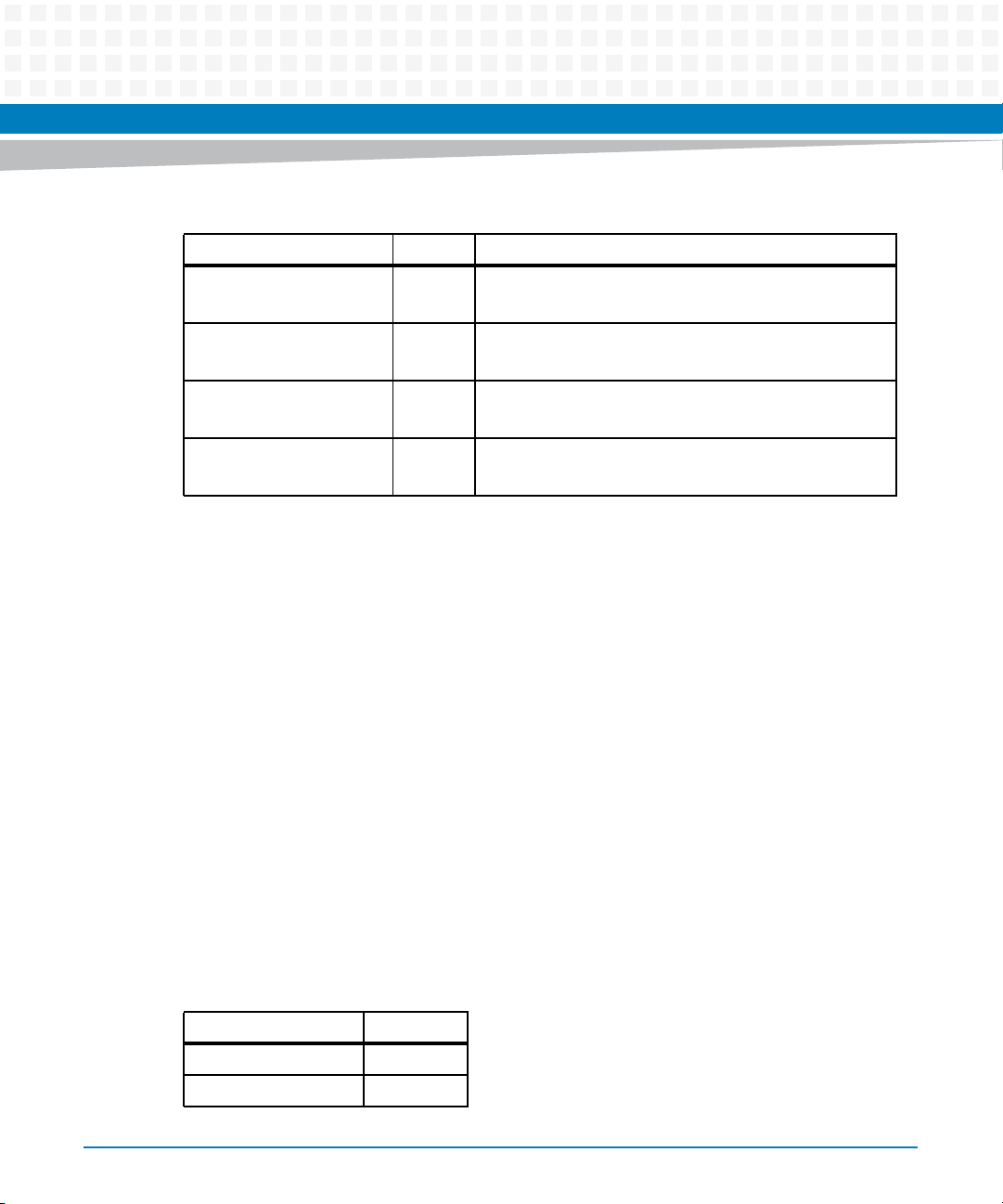
Table 3-1 Face Plate LEDs (continued)
LED Color Description
UPLINK ETH activity
(hub)
Amber Amber: Activity
Off: No activity
UPLINK ETH link
(hub)
MGMT ETH activity
(shelf manager)
MGMT ETH link
(shelf manager)
Green Green: Uplink is available.
Amber Amber: Activity
Green Green: Link to system manager is available.
3.1.2 Ethernet Connectors
Two Ethernet ports are provided via the Ethernet connectors on the face plate. The left
connector (MGMT ETH, 10/100 Mbps) allows external system managers to access the shelf
manager. The right connector (UPLINK ETH, 10/100/1000 Mbps) is the base interface uplink of
the hub.
3.2 Console Connector
The Front Panel has an RJ45 COM 0 connector. The MF106 provides the serial line interface
COM 0 of the Freescale MPC8306S PowerQUICC II Pro microprocessor. The physical
connection is designed as an RS232 interface.
The RS-232D signals are driven by a Maxim MAX3232 transceiver for isolation and signal
qualify. The Front Panel connector type is RJ-45.
Off: Otherwise
Off: No activity
Off: Otherwise
52
Front Panel Pin-out is shown in below table.
Table 3-2 COM 0 Front Panel Serial Port Pin-out Listing
SIGNAL PIN
RTS 1
nc 2
ATCA-MF106 Installation and Use (6806800M62B)
Page 53

Table 3-2 COM 0 Front Panel Serial Port Pin-out Listing (continued)
SIGNAL PIN
TXD 3
Ground 4
Ground 5
RXD 6
nc 7
CTS 8
3.3 Sensors
The IPMC functionality is based on the IPMI specification V1.5.
The IPMI sensors on the ATCA-MF106 are shown in the table below. For further information,
see the ATCA-MF106: Control via IPMI Programmer’s Reference.
Controls, Indicators and Connectors
Table 3-3 ATCA-MF106 Specific Sensors
Type of
Sensor Name
MF106 IPMC OEM 0xD5 Major IPMC events Discrete Always
Boot Bank OEM 0xD2 U-boot sets to indicate
Active Boot OEM 0xD2 The selected boot bank
MF106 FPGA
Ver sio n
FW Revision ISC OEM 0xD6 Revision of ISC firmware Discrete Always
ATCA-MF106 Installation and Use (6806800M62B)
Measurement What Does It Measure?
OEM 0xD6 Revision of FPGA
the currently active boot
bank
during BT interface
initialization
firmware
Sensor/
Reading Type
Class Availability
Discrete Always after
payload has
first been
powered ON
Discrete Always after
payload has
first been
powered ON
Discrete Always after
payload has
first been
powered ON
53
Page 54

Controls, Indicators and Connectors
Table 3-3 ATCA-MF106 Specific Sensors (continued)
Type of
Sensor Name
IPMB0 State IPMB 0xF1 Status of IPMB0 Bus Discrete Always
Measurement What Does It Measure?
Sensor/
Reading Type
Class Availability
Ejector State Button Switch
0x14
MF106 Watchdog Watchdog
20x23
SYS FW PROGRESS System
Firmware
Progress 0x0F
Boot Error Boot Error 0x1E Boot Error Cause Discrete While payload
OS Boot OS Boot 0x1F OS boot information Discrete After OS boot
3.3V Overcurrent Current 0x03 Indicates if the current
Filter Presence Entity Presence
0x25
System Boot System Boot
0x1D
MF106 Temp Temperature
0x01
Ejector Handle State Discrete Always
IPMI timeout
(watchdog) status
U-Boot boot progress Discrete While payload
limit of 3.3 V power
supplied to the
backplane has been
exceeded
Shelf air filter presence Discrete Always
Indicates system boot
origination
MF106 local board
temperature
Discrete Always
powered ON
powered ON
has completed
Discrete Always
Discrete Always
Analog Always
54
MF106 Hotswap Hotswap 0xF0 MF106 Hot Swap Status Discrete Always
ATCA-MF106 Installation and Use (6806800M62B)
Page 55

Board Exchange
4.1 Introduction
This chapter describes how to install the ATCA-MF106 board and includes the following
information:
Before installation
Installing the board in a shelf
Starting up the board
Removing the board
Operation
The system is shipped with pre-installed ATCA-MF106 boards. You have to observe the
following procedures when ordering a board as a spare part or exchanging a board.
Chapter 4
For more information on installing and replacing the ATCA-MF106 board and for a
description of replacement scenarios, see the Centellis 2000 Shelf-DC Installation and Use
manual.
4.2 Before Installation
This section provides the following information:
Requirements
Unpacking and inspecting the board
4.2.1 Requirements
Before you power up the board, calculate the power needed according to your system
configuration.
ATCA-MF106 Installation and Use (6806800M62B)
55
Page 56
Board Exchange
4.2.1.1 Environmental Requirements
You must make sure that the board, when operated in your particular system configuration,
meets the environmental requirements specified below.
Operating temperatures refer to the temperature of the air circulating around the board and
not to the component temperature.
Board Damage
High humidity and condensation on the board surface causes short circuits.
Do not operate the board outside the specified environmental limits. Make sure the board
is completely dry and there is no moisture on any surface before applying power.
56
Table 4-1 Environmental Requirements
Feature Operating Non-Operating (packed state)
Temperature +5 ºC (+41 °F) to +40 ºC (+104 °F)
(normal operation) according to NEBS
Standard GR-63-CORE
-5 °C (+23 °F) to + 55 °C (+131 °F)
(exceptional operation) according to
NEBS Standard GR-63-CORE
Temp. change +/- 0.25 ºC/min according to NEBS
Standard GR-63-CORE
Relative humidity 5% to 90% non-condensing according
to Artesyn Embedded Technologiesinternal environmental requirements
Vibration (tested
in target
platform)
0.1 g from 5 to 100 Hz and back to 5 Hz
at a rate of 0.1 octave/minute.
ATCA-MF106 Installation and Use (6806800M62B)
-40 ºC (-40 °F) to +85 ºC (+185 °F)
+/- 0.25 ºC/min
5% to 95% non-condensing according to
Artesyn Embedded Technologiesinternal environmental requirements
5-20 Hz at 0.01 g
20-200 Hz at -3.0 dB/octave
Random 5-20 Hz at 1 m
Random 20-200 Hz at -3 dB/octave
2
/Hz
2
/Sec
3
Page 57

Table 4-1 Environmental Requirements (continued)
Feature Operating Non-Operating (packed state)
Shock Half-sine, 11 mSec, 30 m/Sec
Free fall - 200 mm/all edges and corners
4.2.1.2 Power Requirements
Make sure that the board is used in an AdvancedTCA shelf connected to -48 VDC up to -60 VDC
(rated voltage), according to Telecommunication Network Voltage (TNV-2).
A TNV-2 circuit is a circuit whose normal operating voltages exceed the limits for a safety-extralow-voltage (SELV) under normal operating conditions, and which is not subject to
overvoltages from telecommunication networks.
Board Exchange
2
Blade level packaging
Half-sine, 6 mSec at 180 m/Sec
1.0 m (packaged) per ETSI 300 019-2-2
(Blade level packaging)
100 mm (unpackaged) per GR-63-CORE
2
On board voltages are 3.3 VDC, 2.5 VDC, 1.8 VDC and 1.0 VDC:
3.3 V voltage is generated from the -48 V AdvancedTCA power by a DC/DC converter with
galvanic isolation suitable for TNV-2 circuits.
2.5 V, 1.8 V and 1.0 V voltages are derived from the 3.3 V power.
Table 4-2 DC Board Power Requirements
Feature Value
Rated Voltage -48 VDC to -60 VDC
Operating Voltage -39 VDC to -72 VDC
Input current 0.2 A
ATCA-MF106 power dissipation 10 W (max.) including external load of 4 W maximum
ATCA-MF106 Installation and Use (6806800M62B)
US and Canada: -48 VDC
US and Canada: -39 VDC to -60 VDC
57
Page 58
Board Exchange
The board provides two independent power inputs according to the AdvancedTCA
specification. Each input has to be equipped with an additional fuse of max. 90 A located either
in the shelf where the board is installed or the power entry module (PEM).
4.2.1.3 Required Equipment
Gather the following equipment before starting:
Screwdriver
ESD wrist strap
4.2.2 Unpacking and Inspecting the Board
58
Board Damage
Touching the board or electronic components in a non-ESD protected environment causes
component and board damage.
Before touching boards or electronic components, make sure that you are working in an
ESD-safe environment or wear ESD wrist straps.
Shipment Inspection
To inspect the shipment, perform the following steps:
1. Verify that you have received all items of your shipment:
Printed user manual
ATCA-MF106
Any optional items ordered
ATCA-MF106 Installation and Use (6806800M62B)
Page 59
2. Check for damage and report any damage or differences to the customer service.
3. Remove the desiccant bag delivered together with the board and dispose of it
according to your country’s legislation.
The board is thoroughly inspected before shipment. If any damage occurred during
transportation or any items are missing, please contact our customer's service immediately.
4.3 Installing the Board
Before starting to install the board, observe the following:
Board Exchange
Board Damage
Touching the board or electronic components in a non-ESD protected environment causes
component and board damage.
Before touching boards or electronic components, make sure that you are working in an
ESD-safe environment or wear ESD wrist straps.
Since the backplane has no possibility to store the information on the shelf (part number, serial
number, etc.), this information is stored in the boards themselves. The software on the board
always updates this information on a newly inserted board.
Never exchange more than one of these FRUs (boards) at the same time to guarantee
that the shelf information stays consistent and up to date.
The board must only be operated in a shelf that is properly grounded.
ATCA-MF106 Installation and Use (6806800M62B)
59
Page 60

Board Exchange
4.3.1 Installing the Board
To install the board into an AdvancedTCA shelf, proceed as follows.
Installation Procedure
The following procedure describes the installation of the board. It assumes that your system is
powered. If your system is unpowered, you can disregard the blue LED and thus skip the
respective step. In this case it is a purely mechanical installation.
1. Put on an ESD wrist strap.
2. Connect the strap to the shelf by attaching the front or rear ESD jack /ESD snap.
3. Insert the board into the shelf by placing the left and right edges of the board in the
card guides of the shelf. Ensure that the guiding module of shelf and board are
aligned properly. The alignment pin facilitates the insertion and prevents bent pins.
4. Slide the board into the shelf by using the extraction handles until you feel
resistance.
5. Wait until the blue LED is illuminated.
6. Tighten the screws on the left and on the right of the board.
In this way the handle switch activator is closed and the board can be powered. The
blue LED blinks.
7. Wait until the blue LED is switched off.
The switched off blue LED indicates that the board is activated.
8. Attach cables to the front panel connectors as necessary.
4.3.2 Removing the Board
This section describes how to remove the board from an AdvancedTCA system.
60
ATCA-MF106 Installation and Use (6806800M62B)
Page 61

Board Exchange
Removal Procedure
The following procedure describes how to remove the board from a system. It assumes that the
system is powered. If the system is unpowered, you can disregard the blue LED and thus skip
the respective step. In that case it is a purely mechanical procedure.
1. To extract the active shelf manager initiate a switchover. Otherwise continue with
the next step.
2. Put on an ESD wrist strap.
3. Connect the strap to the shelf by attaching it to the front or rear ESD jack /ESD snap.
4. Remove any cables that are attached to front panel connectors.
5. Unfasten the screws of the face plate until the handle is detached from the front
panel of the board.
The handle switch activator triggers the blinking of the blue LED. The hotswap state
remains in the state "extraction pending", so that the blue LED is still blinking.
6. Wait until the blue LED is illuminated.
7. Remove the board from the shelf using the extraction handles.
ATCA-MF106 Installation and Use (6806800M62B)
61
Page 62

Board Exchange
62
ATCA-MF106 Installation and Use (6806800M62B)
Page 63

Shelf Manager File System
5.1 Persistent File Support
The root-file system includes all payload applications and configurations. It is stored as a
compressed RAM disk on the flash and extracted into the RAM after the kernel has booted. All
changes in the disk file system are lost after the shelf manager powers down.
To enable persistent file support, a separate journaling flash file system of type ext2 exists. This
ext2 file system is mounted at startup on the /usr/local mount point. Any files stored in
this directory are persistent.
5.1.1 Persistent File Support
In order to be able to make files persistent that are usually located under the RAM disk root-file
system Artesyn Embedded Technologies has implemented a persistent file mechanism. All
files that should be stored under the persistent file system instead of the RAM disk file system
are listed in a persistent file map. The file map is stored with the following file path:
Chapter 5
/etc/persistentmap
For each file that should be persistent a separate line in the persistent map exists.
The following example shows the default persistent map of the shelf manager.
#
# Map of persistent files.
# This file is sourced during system startup.
# A file specified in the first row is replaced by a symbolic link that
# points to the file in the second row. If the file in the second row
# does not exist it is copied first.
#
# Copyright (c) 2011 Emerson Network Power - Embedded Computing, Inc.
#
#
ATCA-MF106 Installation and Use (6806800M62B)
63
Page 64

Shelf Manager File System
# SYNTAX
# ------
# <source file on volatile media> <destination file on persistent media>
#
/etc/network.conf /usr/local/etc/network.conf
/etc/rc.d/network.local /usr/local/etc/rc.d/network.local
/etc/appl.conf /usr/local/etc/appl.conf
/opt/bladeservices/etc/bbs-hpib/bbs-hpib.conf /usr/local/etc/bbshpib/bbs-hpib.conf
/var/lib/bbs-hpib/uid_map /usr/local/var/lib/bbs-hpib/uid_map
/etc/ntpd.conf /usr/local/etc/ntpd.conf
/var/lib/dhcp/dhcpd.leases /usr/local/var/lib/dhcp/dhcpd.leases
/etc/dhcpd.conf /usr/local/etc/dhcpd.conf
Each line consists of two columns. The first column specifies the source file which is the file on
the RAM disk file system. The second column specifies the destination file which is the file on
the persistent file system.
At system startup the shelf manager reads the persistent map and replaces each source file
with a symbolic link to the destination file. If the destination file does not exist it will be copied
from the RAM disk file system to the persistent file system first. The persistent map itself is also
symlinked at startup from the RAM disk file system to the persistent file system. A default map
is copied if it does not already exists.
64
ATCA-MF106 Installation and Use (6806800M62B)
Page 65

Using this approach any file in the RAM disk file system, with the exception of
/etc/rc.d/rc.boot, can be made persistent.
Replacing a regular file by a symbolic link is transparent to the applications on the shelf
manager.
5.1.2 Use Cases
The following use cases are described in this section:
How to make a file on the RAM disk file system persistent
How to remove a file from the persistent file system
How to rollback to the factory configuration
Shelf Manager File System
5.1.2.1 How to Make a File on the RAM Disk File System Persistent
1. Prepare for editing the persistent map.
Either connect to the shelf manager via telnet and start "vi" to edit the persistent map on
site or download the persistent map using ftp to your local workstation and load the file in
your favorite editor.
2. Add a new line at the end of the persistent map.
The first entry of the line specifies a file on the RAM disk file system and the second line
entry specifies the file on the persistent file system.
3. Save your changes.
If you edit on site exit the "vi" editor or otherwise, upload your modified file to the shelf
manager using ftp.
4. (Optional) Create the file on the persistent file system.
This step allows you to install your own file on the persistent file system. If this step is
omitted, the existing file on the RAM disk file system is copied automatically during system
startup.
5. Reboot your system
After system reboot the file on the persistent media is used instead of the file on the RAM
disk.
ATCA-MF106 Installation and Use (6806800M62B)
65
Page 66

Shelf Manager File System
5.1.2.2 How to Remove a File from the Persistent File System
1. Prepare for editing the persistent map.
Either connect to the shelf manager via telnet and start "vi" to edit the persistent map on
site or download the persistent map with ftp to your local workstation and load the file in
your favorite editor.
2. Remove the line containing the desired file.
3. Save your changes.
If you edit on site, exit the "vi" editor or otherwise upload your modified file to the shelf
manager using ftp.
4. Remove the file on the persistent file system (optional).
This step is optional because the shelf manager does not use the file on persistent media
any longer.
5. Reboot your system.
After system reboot the file on the RAM disk is used.
5.1.2.3 How to Rollback Factory Configuration
1. Type the following command to delete all data on the persistent media:
# cd /usr/local && rm -rf *
2. Reboot your system.
5.1.2.4 Persistent Log Files
All log files in /var/log directory are saved in the persistent file area. The /var/log directory is a
symbolic link to /usr/local/var/log. Upon reboot of the Shelf Manager, all files stored in
/usr/local/var/log are moved to /usr/local/var/log.PREVIOUS. This allows two separate set of
log files to be saved - the current logs in /usr/local/var/log and the logs from the previous boot
in /usr/local/var/log.PREVIOUS.
66
ATCA-MF106 Installation and Use (6806800M62B)
Page 67
5.2 Log Files
There are three types of log files:
1. Linux log files
2. HPI log file (see System Management Interface Based on HPI-B (Centellis CO 31kX/4100/2000)
User’s Guide, chapter "HPI Logging Support")
3. Supervisor log file
Per default, the log file for supervisor logging is located at /var/log/supervisor.log.
You have the possibility to configure the supervisor logging by changing the configuration file
located at /usr/etc/supervisor/config/sv_config.xml. This XML file allows you to change the
following elements:
Element Description Possible Values
Shelf Manager File System
LogSeverity mask Defines what information
will be logged
LogSink mask Defines where the
information will be
logged
LogFile name Where is the logfile
located?
LogFile size Maximum log file size Default: 500 KB
Silent|Trace|Info|Notice|Warning|Error|Critical
|Alert|Emergency|Everything
Stdout|Stderr|Logfile|Syslog
Default: /var/log/supervisor.log
The IP addresses in the log file are dynamic. Only change the elements listed in the table
above.
Here is an example of what the configuration file might look like:
<SupervisorConfiguration>
<Logging>
<!-- possible severity values:
ATCA-MF106 Installation and Use (6806800M62B)
67
Page 68

Shelf Manager File System
Silent|Trace|Debug|Info|Notice|Warning|Error|Critical|Alert|Emergency|Eve
rything -->
<LogSeverity
mask="Info|Notice|Warning|Error|Critical|Alert|Emergency" />
<!-- possible sink values: Stdout|Stderr|Logfile|SysLog -->
<LogSink mask="Logfile"/>
<LogFile name="/var/log/supervisor.log" size="500"/>
</Logging>
<Supervisor msgPort="5566" queueLen="100" filePort="5568"
sendChunkSize="500"
startWaitTime="100" restartWaitTime="1000" transitionMaxTime="20000"
switchWaitTime="30000"
switchIgnoreTime="5000" tieBreak="8" localConnectOnly="0"
fileInterface="0.0.0.0"/>
<!-- for file transfer using ppp interface fileInterface="@srcIpAddr1@"
-->
<HeartBeater id="1" port="5567" type="UDP">
<HeartBeaterGroup name="shmgr" id="1" >
<HeartBeaterNode id="1" ipAddr="192.168.101.9" port="5567"
interval="400" warning="3" inaccessible="5" />
<HeartBeaterNode id="2" ipAddr="192.168.102.9" port="5567"
interval="400" warning="3" inaccessible="5" />
</HeartBeaterGroup>
</HeartBeater>
</SupervisorConfiguration>
68
ATCA-MF106 Installation and Use (6806800M62B)
Page 69
Firmware Upgrade Facility
6.1 Overview
The Firmware Upgrade Facility (FUF) provides a uniform way to upgrade firmware on Artesyn
hub blades, node blades, and AMC modules. It consists of a Firmware Upgrade Command-line
Utility (FCU), flash device drivers, and specially prepared firmware recovery image files.
The ATCA-MF106 ramdisk is upgraded using the flashcp utility instead of fcu.
6.2 Firmware Recovery Image Files
Chapter 6
FCU supports specially prepared firmware recovery image (FRI) files as well as firmware images
in the HPM.1 format. HPM.1 is a PICMG standard to upgrade IPMCs.
By default, the image files for the current hardware configurations are stored in
/opt/bladeservices/rom.
The following image files are currently supported:
Filename Description
atca-mf106-kernel.fri Kernel image for ATCA-MF106
atca-mf106-cpu.fri U-boot firmware image for ATCA-MF106
atca-mf106-dtb.fri Device Tree Binary for ATCA-MF106
6.3 Backup Concept
When upgrading the U-Boot firmware, or Device Tree Binary image, or Linux kernel, FCU only
writes into the currently stand-by bank. After the upgrade, the stand-by bank must be marked
for next use; this means it will be executed after the next reboot.
ATCA-MF106 Installation and Use (6806800M62B)
69
Page 70

Firmware Upgrade Facility
6.4 fcu—Firmware Upgrade Command-Line Utility
Description
The Firmware Upgrade Command-line Utility (FCU) allows you to:
Query the current versions of firmware installed on the Shelf Manager and determine
which firmware devices are active.
Verify that a specified upgrade image is sound and compatible with the current hardware.
Upgrade a firmware image.
Mark a device to be used as the boot source on the next reset.
By default, the FCU binary executable is installed in /opt/bladeservices/bin. This directory has
been added to the PATH environment variable.
The FCU verify and upgrade operations require specially prepared FRI files or HPM files (see
Firmware Recovery Image Files on page 69).
70
Synopsis
fcu --help [-t<slave address>]
fcu --version
fcu -q [-d <device-id>] [-t<slave address>]
fcu -v -f <filename> [-t<slave address>]
fcu -u -f <filename> [-t<slave address>]
fcu -a -f <filename>
fcu -m -b <bank-letter> -d <device-id> [-t<slave address>]
fcu -s -f <filename>
fcu --activate -b <bank-letter> -d <device-id>
Parameters
-a
--full-upgrade
ATCA-MF106 Installation and Use (6806800M62B)
Page 71

Firmware Upgrade Facility
This option is a shortcut for performing the verify, upgrade, and mark operations. The file
option -f is required. This option should not be combined with other operations.
-r
--activate
This command is available for IPMC devices and images which conform to the HPM.1 standard.
HPM.1 compliant IPMCs store a redundant set of firmware images which may have the states
operational, rollback or deferred. Using the --activate option, you can set the state of the
addressed firmware bank to "operational". Unlike the --mark option, the --activate
command does not affect the payload operation, this means you can set a previously "rollback"
firmware bank to "operational" without rebooting or resetting the payload. The target IPMC is
immediately functional after switching to the new firmware.
You can obtain the current states of the firmware banks by using the -q command. The state
appears as part of the bank name, for example: "B - Rollback".
-b <bank-letter>
--bank=<bank-letter>
Specifies a flash bank (A or B, for example), where <bank-letter> is the letter designating a
specific bank. This option can be used with the mark or activate operation. Use the query
option -q to list available banks.
-d <device-id>
--device=<device-id>
Specifies a target firmware device, where <device-id> is the name of the device. This option
is used with the mark or query operations. Device ID values vary by hardware. You can display
supported devices on a given blade by using fcu --help. Currently supported values are
listed in the following table.
Device ID Description
atca-mf106-cpu U-Boot firmware device for ATCA-MF106
atca-mf106-dtb Device Tree Binary device for ATCA-MF106
atca-mf106-kernel Kernel device of ATCA-MF106
atca-mf106-rootfs Root filesystem (ramdisk) device for ATCA-MF106
atca-mf106-ipmc IPMC firmware device
ATCA-MF106 Installation and Use (6806800M62B)
71
Page 72

Firmware Upgrade Facility
-f <filename>
--file=<filename>
Specifies the FRI file, where <filename> is the complete path and filename of the image file.
This option is used with the verify and upgrade operations.
--force
This option allows the installation of images with non-matching part-number and part-revision
FRU data fields. This option should be used with extreme caution only because installing an
incompatible image on a device may render it inoperable.
--help
Displays a brief message describing command usage. It also displays a list of the devices
supported on the blade. This option is exclusive and should not be used with other options.
-m
--mark
72
Tells FCU to set the boot select so that on the next boot the specified firmware bank will be
active. When mark is combined with the upgrade operation, there is no need to specify a bank;
the bank just upgraded will be marked. Otherwise, you must specify a bank and a device.
Note that on the ATCA-MF106 the U-Boot, DTB, Kernel, and Ramdisk are coupled, this means
when you mark a U-Boot image for the next reboot, the other corresponding images are
automatically marked as well.
-q
--query
Tells FCU to return firmware information for a specific device (if used with -d) or information
about all firmware devices. The query operation is exclusive and is not intended to be
combined with other operations.
-s
--show
Shows detailed information about a specified file. The information shown includes for example
image type, version, manufacturer name etc. This command may be useful before a firmware
upgrade to determine the version of a new image file.
ATCA-MF106 Installation and Use (6806800M62B)
Page 73

Firmware Upgrade Facility
-t
--target
This option is needed to specify the IPMC address if the operation is to be done on a remote
IPMC. If you do not specify this option, the software tries to access the local IPMC. The -t
option provides a possibility to perform the firmware upgrade on a different blade.
-u
--upgrade
Tells FCU to upgrade the currently inactive bank of the device specified by the target FRI file.
The file option -f is required. The upgrade operation may be combined with the verify and
mark operations.
-v
--verify
Tells FCU to verify the image file specified by the required -f option. This operation verifies that
the specified file is sound and compatible with the current hardware. The verify operation may
be combined with the upgrade and mark operations.
--version
Displays version information for the utility. This option is exclusive and should not be used with
other options.
Usage
Some FCU options can be combined. Some options are exclusive. The following list describes
the valid option combinations:
--full-upgrade --file=<filename>
--full-upgrade --file=<filename> --target=xxxxxx
--help
--mark --bank=<bank-letter> --device=<device-id>
--query
--query --device=<device-id>
--show --file=<filename>
ATCA-MF106 Installation and Use (6806800M62B)
73
Page 74

Firmware Upgrade Facility
--upgrade --file=<filename>
--upgrade --mark --file=<filename>
--upgrade --file=<filename> --target=xxxxxx
--verify --file=<filename>
--verify --upgrade --file=<filename>
--activate --bank=<bankletter> --device=<deviceID>
--verify --upgrade --mark --file=<filename>
--version
Multi character options may be abbreviated so long as they are unique. For example, --full
is equivalent to --full-upgrade. Typing --ver, however, will not work since it matches
both --verify and --version.
Single-character options may be combined without repeating the hyphen, as in these
examples:
74
fcu –vf /opt/bladeservices/rom/<filename>
fcu –q –d <device-id>
fcu –q -t 0x90 <device-id>
fcu –mb a –d <device-id>
Options are not case-sensitive. For example, --help is equivalent to --HeLp. However,
option arguments, such as filename and device ID, are case-sensitive.
When upgrading firmware, it is strongly recommended that you upgrade only one device at a
time. While FCU performs many checks during upgrade to ensure success, if something goes
wrong and both firmware banks become corrupted, the blade will be inoperable.
ATCA-MF106 Installation and Use (6806800M62B)
Page 75

6.5 Upgrading Firmware
This section describes recommended procedures for upgrading firmware devices.
6.5.1 Upgrading CPU Firmware
Upgrading CPU Firmware
Follow these steps to upgrade the CPU firmware (U-Boot):
1. Query the current and backup U-Boot firmware on the ATCA-MF106:
# fcu -qd atca-mf106-cpu
2. Show the version of the new U-Boot image:
# fcu -s -f /opt/bladeservices/rom/atca-mf106-cpu.fri
3. If the U-Boot image is newer than the current version, upgrade the U-Boot
firmware:
# fcu -v -u -f /opt/bladeservices/rom/atca-mf106-cpu.fri
Firmware Upgrade Facility
4. Query the device to ensure that the backup was upgraded:
# fcu –qd atca-mf106-cpu
6.5.2 Upgrading the Device-Tree Blob
Upgrading the Device-Tree Blob
Follow these steps to upgrade the device-tree blob:
1. Query the current and backup device-tree blob images.
# fcu -q -d atca-mf106-dtb
2. Show the version of the new device-tree blob:
# fcu -s -f /opt/bladeservices/rom/atca-mf106-dtb.fri
3. If the device-tree-blob version in the release is newer than the current version
installed, upgrade the device-tree blob.
# fcu -v -u -f /opt/bladeservices/rom/atca-mf106-dtb.fri
ATCA-MF106 Installation and Use (6806800M62B)
75
Page 76

Firmware Upgrade Facility
4. Query the device to ensure that the backup was upgraded:
# fcu -q -d atca-mf106-dtb
6.5.3 Upgrading the Kernel
Upgrading the Kernel
Follow these steps to upgrade the kernel:
1. Query the current and backup kernel images.
# fcu -q -d atca-mf106-kernel
2. Show the version of the new kernel:
# fcu -s -f /opt/bladeservices/rom/atca-mf106-kernel.fri
3. If the kernel version in the release is newer than the current version installed,
upgrade the kernel.
# fcu -v -u -f /opt/bladeservices/rom/atca-mf106-kernel.fri
4. Query the device to ensure that the backup was upgraded:
# fcu -q -d atca-mf106-kernel
6.5.4 Upgrading the Ramdisk
Upgrading the Ramdisk
The ramdisk cannot be updated with fcu. Instead, the flashcp utility is used to upgrade the
ramdisk. The flashcp utility does not upgrade the backup bank, but it upgrades the currently
selected bank. Also, the ramdisk must be copied to the ATCA-MF106 and placed into
/usr/local/ directory in order to upgrade due to the size of the ramdisk image.
To upgrade the ramdisk, follow these steps to change the selected bank. After the upgrade,
change the selected bank again:
1. To see the currently selected bank, run fcu to query the U-Boot version. If "yes", next to
"Marked for next use" in the example below indicates that bank A is the currently selected
boot bank. The currently booted bank is shown with the tag "Firmware was booted from
this bank".
76
ATCA-MF106 Installation and Use (6806800M62B)
Page 77

Firmware Upgrade Facility
fcu -q -d atca-mf106-cpu
fcu version bbs 1.3.10 build 2.wrspne3.0
********************[[[[[REPORT BEGIN]]]]]********************
OPERATION : Query
RESULT : SUCCESS
MESSAGE : Device : atca-mf106-cpu
Part number : 0000E0
Part revision : C
BANK : A
Firmware Name : U-Boot
Firmware Version : U-Boot 2010.06.3 (Mar 14 2011 13:43:07) MPC83XX
Marked for next use : yes
Firmware was booted from this bank
BANK : B
Firmware Name : U-Boot
Firmware Version : U-Boot 2010.06.2 (Mar 01 2011 10:06:53) MPC83XX
Marked for next use : no
********************[[[[[ REPORT END ]]]]]********************
ATCA-MF106 Installation and Use (6806800M62B)
77
Page 78

Firmware Upgrade Facility
2. Switch the selected bank to A or B:
# fcu --mark --bank=A --device=atca-mf106-cpu
or
# fcu --mark --bank=B --device=atca-mf106-cpu
3. Upgrade the ramdisk using flashcp:
# flashcp -v /usr/local/ramdisk.image.gz /dev/mtd4
4. Switch the selected bank back to A or B:
# fcu --mark --bank=A --device=atca-mf106-cpu
or
# fcu --mark --bank=B --device=atca-mf106-cpu
5. Query the device to ensure that the backup was upgraded successfully:
# fcu -q -d atca-mf106-rootfs
6.5.5 Activating the Backup Boot Bank
After upgrading the backup boot bank with new U-Boot, device-tree blob, kernel, and ramdisk
images, the backup boot bank must be marked as active for next boot and reboot the system.
Activating the Backup Boot Bank via FCU
1. To mark the backup boot bank, first query which bank is "Marked for next use":
# fcu -q -d atca-mf106-cpu
2. Mark the backup boot bank for next use after the next reboot.
If Bank A is "Marked for next use", mark Bank 'B' for the next reboot.
# fcu -mb B -d atca-mf106-cpu
If Bank B is "Marked for next use", mark Bank 'A' for the next reboot.
# fcu -mb A -d atca-mf106-cpu
The -mb option allows you to select which boot bank to use at the next boot and is done
through marking U-Boot. By extension, using the -mb option to mark U-boot also marks the
device-tree blob, kernel, and ramdisk as well. All three must be at the desired version in the
target bank while booting that bank.
78
ATCA-MF106 Installation and Use (6806800M62B)
Page 79

3. Reboot the blade:
# reboot
6.5.6 Upgrading IPMC Firmware
Upgrading IPMC Firmware
Follow these steps to upgrade the IPMC firmware. The IPMC firmware becomes active
immediately after the successful upgrade.
1. Copy the IPMC firmware file to the ATCA-MF106 in the /root directory. The
firmware file is not stored within the ramdisk.
2. Query the current IPMC firmware on the ATCA-MF106.
# fcu -q -d atca-mf106-ipmc
Firmware Upgrade Facility
3. Show the version of the new IPMC image.
# fcu -s -f /root/ATCA_MF106-upgrade-<version>.hex
4. If the IPMC version in the release is newer than the current version installed,
upgrade the IPMC firmware.
# fcu -v -u -f /root/ATCA_MF106-upgrade-<version>.hex
5. Query the IPMC to ensure the new version is installed and activated.
# fcu -q -d atca-mf106-ipmc
6.5.7 Example Upgrade Procedure
The following procedure should be followed to upgrade to a new release of firmware/software
on a pair of Shelf Managers.
In the procedure below, ShM A and ShM B reference the standby and active ShMs, respectively.
1. Copy the new atca-mf106-cpu.fri, atca-mf106-dtb.fri, atca-mf106-
kernel.fri, and ramdisk.image.gz files to /usr/local on ShM A.
2. Copy ATCA_MF106-upgrade-<version>.hex file to /root on ShM B.
ATCA-MF106 Installation and Use (6806800M62B)
79
Page 80

Firmware Upgrade Facility
3. On ShM A, upgrade U-Boot, Kernel, and DTB on the inactive bank using fcu.
fcu -vuf /usr/local/atca-mf106-cpu.fri
fcu -vuf /usr/local/atca-mf106-dtb.fri
fcu -vuf /usr/local/atca-mf106-kernel.fri
4. On ShM A, check the currently marked boot bank.
fcu -q -d atca-mf106-cpu
5. On ShM A, swap boot banks to allow for ramdisk upgrade. Choose A or B based on the
result of the previous step.
fcu --mark --bank=<A|B> --device=atca-mf106-cpu
6. On ShM A, program the ramdisk:
flashcp -v /usr/local/ramdisk.image.gz /dev/mtd4
7. There may be changes to files normally stored in the persistent file area when upgrading.
Refer to the ATCA-MF106 Release Notes for more information. If there are no files in the
persistent file area that need to be saved across a reboot (i.e. user specific files or changes
to configuration files), the persistent file area can be cleared later (before rebooting the
Shelf Manager).
80
8. Run fcu on ShM B to upgrade ShM A's IPMI FW. Use IPMB address 0x10 for the Shelf
Manager in the left slot and 0x12 for the right slot.
fcu -t 0x<10|12> -uvf /root/ATCA_MF106-upgrade-<version>.hex
9. After upgrade, ShM A will NOT reboot. If this is the second time through the upgrade
procedure, and both ShMs are upgraded, skip to Step 12.
10. From ShM B, switchover the Shelf Managers:
sv_deactivate
11. Repeat the above process to upgrade the other Shelf Manager and then continue to the
next step.
12. After upgrade, clean out the upgrade files from both the Shelf Managers.
rm /root/ATCA_MF106-upgrade-<version>.hex
rm /usr/local/atca-mf106-cpu.fri
rm /usr/local/atca-mf106-dtb.fri
rm /usr/local/atca-mf106-kernel.fri
rm /usr/local/ramdisk.image.gz
ATCA-MF106 Installation and Use (6806800M62B)
Page 81

Firmware Upgrade Facility
13. Clear the persistent file area or verify that necessary changes are made according to the
ATCA-MF106 Release Notes. Reboot both Shelf Managers by issuing the below command
from the Linux command line:
reboot
ATCA-MF106 Installation and Use (6806800M62B)
81
Page 82

Firmware Upgrade Facility
82
ATCA-MF106 Installation and Use (6806800M62B)
Page 83
Appendix A
A Related Documentation
A.1 Artesyn Embedded Technologies - Embedded
Computing Documentation
The publications listed below are referenced in this manual. You can obtain electronic copies of
Artesyn Embedded Technologies - Embedded Computing publications by contacting your
local Artesyn sales office. For released products, you can also visit our Web site for the latest
copies of our product documentation.
1. Go to www.artesyn.com/computing/support/product/technical-documentation.php.
2. Under FILTER OPTIONS, click the Document types drop-down list box to select the type of
document you are looking for.
3. In the Search text box, type the product name and click GO.
Table A-1 Artesyn Embedded Technologies - Embedded Computing Publications
Document Title Publication Number
Centellis 2000 Shelf-DC Installation and Use 6806800G45
Centellis 2000 Release 3.0 Installation and Use 6806800L99
ATCA-MF106: Control via IPMI Programmer’s Reference 6806800M33
System Management Interface Based on HPI-B (Centellis
CO 31kX/4100/2000) User’s Guide
A.2 Related Specifications
For additional information, refer to the following table for related specifications. As an
additional help, a source for the listed document is provided. Please note that, while these
sources have been verified, the information is subject to change without notice.
Table A-2 Related Specifications
Organization Document Title
Intel
http://developer.intel.com/design/servers/
ipmi/
6806800D84
Platform Management FRU Information Storage
Definition v1.0
IPMI Specification v1.5
ATCA-MF106 Installation and Use (6806800M62B)
83
Page 84
Related Documentation
Table A-2 Related Specifications (continued)
Organization Document Title
PICMG
http://www.picmg.org
Service Availability Forum
http://www.saforum.org
PICMG 3.0 Revision 3.0 Advanced TCA Base
Specification
Service Availability Forum Hardware Platform Interface
SAI-HPI-A01.01
84
ATCA-MF106 Installation and Use (6806800M62B)
Page 85

Page 86
Artesyn Embedded Technologies, Artesyn and the Artesyn Embedded Technologies logo are trademarks and service marks of Artesyn Embedded Technologies, Inc.
All other product or service names are the property of their respective owners.
©
2014 Artesyn Embedded Technologies, Inc.
 Loading...