

Page 1

ATCA-9305
User’s Manual
P/N: 10009109-07
May 2014
Page 2

©
Copyright 2014 Artesyn Embedded Technologies, Inc.
All rights reserved.
Trademarks
Artesyn Embedded Technologies, Artesyn and the Artesyn Embedded Technologies logo are trademarks and service marks of
Artesyn Embedded Technologies, Inc.© 2014 Artesyn Embedded Technologies, Inc. All other product or service names are the
property of their respective owners.
Intel® is a trademark or registered trademark of Intel Corporation or its subsidiaries in the United States and other countries.
Java™ and all other Java-based marks are trademarks or registered trademarks of Oracle America, Inc. in the U.S. and other countries.
Microsoft®, Windows® and Windows Me® are registered trademarks of Microsoft Corporation; and Windows XP™ is a trademark of
Microsoft Corporation.
PICMG®, CompactPCI®, AdvancedTCA™ and the PICMG, CompactPCI and AdvancedTCA logos are registered trademarks of the PCI
Industrial Computer Manufacturers Group.
UNIX® is a registered trademark of The Open Group in the United States and other countries.
Notice
While reasonable efforts have been made to assure the accuracy of this document, Artesyn assumes no liability resulting from any
omissions in this document, or from the use of the information obtained therein. Artesyn reserves the right to revise this document
and to make changes from time to time in the content hereof without obligation of Artesyn to notify any person of such revision or
changes.
Electronic versions of this material may be read online, downloaded for personal use, or referenced in another document as a URL to
an Artesyn website. The text itself may not be published commercially in print or electronic form, edited, translated, or otherwise
altered without the permission of Artesyn.
It is possible that this publication may contain reference to or information about Artesyn products (machines and programs),
programming, or services that are not available in your country. Such references or information must not be construed to mean that
Artesyn intends to announce such Artesyn products, programming, or services in your country.
Limited and Restricted Rights Legend
If the documentation contained herein is supplied, directly or indirectly, to the U.S. Government, the following notice shall apply
unless otherwise agreed to in writing by Artesyn.
Use, duplication, or disclosure by the Government is subject to restrictions as set forth in subparagraph (b)(3) of the Rights in
Technical Data clause at DFARS 252.227-7013 (Nov. 1995) and of the Rights in Noncommercial Computer Software and
Documentation clause at DFARS 252.227-7014 (Jun. 1995).
Contact Address
Artesyn Embedded Technologies Artesyn Embedded Technologies
Marketing Communications
2900 S. Diablo Way, Suite 190
Tempe, Arizona 85282
Lilienthalstr. 17-19
85579 Neubiberg/Munich
Germany
Page 3

Regulatory Agency Warnings & Notices
The Artesyn ATCA-9305 meets the requirements set forth by the Federal Communications
Commission (FCC) in Title 47 of the Code of Federal Regulations. The following information is
provided as required by this agency.
This device complies with part 15 of the FCC Rules. Operation is subject to the following two
conditions: (1) This device may not cause harmful interference, and (2) this device must accept
any interference received, including interference that may cause undesired operation.
FCC Rules and Regulations – Part 15
This equipment has been tested and found to comply with the limits for a Class AClass B digital
device, pursuant to part 15 of the FCC Rules. These limits are designed to provide reasonable
protection against harmful interference when the equipment is operated in a commercial
environmentin a residential installation. This equipment generates, uses and can radiate radio
frequency energy and, if not installed and used in accordance with the instructions, may cause
harmful interference to radio communications. Operation of this equipment in a residential
area is likely to cause harmful interference, in which case the user will be required to correct the
interference at his own expense.
Making changes or modifications to the ATCA-9305 hardware without the explicit consent of
Artesyn Embedded Technologies could invalidate the user’s authority to operate this
equipment.
EMC Compliance
The electromagnetic compatibility (EMC) tests used an ATCA-9305 model that includes a front
panel assembly from Artesyn Embedded Technologies.
ATCA-9305 User’s Manual (10009109-07)
3
Page 4

Regulatory Agency Warnings & Notices
GR-1089-CORE STANDARD
The intra-building port(s) of the equipment or subassembly is suitable for connection to
intrabuilding or unexposed wiring or cabling only. The intra-building port(s) of the equipment
or subassembly MUST NOT be metallically connected to interfaces that connect to the OSP or
its wiring. These interfaces are designed for use as intra-building interfaces only (Type 2 or
Type 4 ports as described in GR-1089-CORE, Issue 4) and require isolation from the exposed
OSP cabling. The addition of Primary Protectors is not sufficient protection in order to connect
these interfaces metallically to OSP wiring.
4
ATCA-9305 User’s Manual (10009109-07)
Page 5

Contents
Contents
Regulatory Agency Warnings & Notices . . . . . . . . . . . . . . . . . . . . . . . . . . . . . . . . . . . . . . . . . . . . . . . . . . . . . 3
Safety Notes . . . . . . . . . . . . . . . . . . . . . . . . . . . . . . . . . . . . . . . . . . . . . . . . . . . . . . . . . . . . . . . . . . . . . . . . . . . . . 21
Sicherheitshinweise . . . . . . . . . . . . . . . . . . . . . . . . . . . . . . . . . . . . . . . . . . . . . . . . . . . . . . . . . . . . . . . . . . . . . . 25
About this Manual . . . . . . . . . . . . . . . . . . . . . . . . . . . . . . . . . . . . . . . . . . . . . . . . . . . . . . . . . . . . . . . . . . . . . . . 31
1 Overview . . . . . . . . . . . . . . . . . . . . . . . . . . . . . . . . . . . . . . . . . . . . . . . . . . . . . . . . . . . . . . . . . . . . . . . . . . . . 37
1.1 Components and Features . . . . . . . . . . . . . . . . . . . . . . . . . . . . . . . . . . . . . . . . . . . . . . . . . . . . . . . . . . . 37
1.2 Functional Overview . . . . . . . . . . . . . . . . . . . . . . . . . . . . . . . . . . . . . . . . . . . . . . . . . . . . . . . . . . . . . . . . 40
1.3 Additional Information . . . . . . . . . . . . . . . . . . . . . . . . . . . . . . . . . . . . . . . . . . . . . . . . . . . . . . . . . . . . . . 41
1.3.1 Product Certification . . . . . . . . . . . . . . . . . . . . . . . . . . . . . . . . . . . . . . . . . . . . . . . . . . . . . . . . . 41
1.3.2 RoHS Compliance . . . . . . . . . . . . . . . . . . . . . . . . . . . . . . . . . . . . . . . . . . . . . . . . . . . . . . . . . . . . 42
1.3.3 Terminology and Notation . . . . . . . . . . . . . . . . . . . . . . . . . . . . . . . . . . . . . . . . . . . . . . . . . . . . 44
2 Setup . . . . . . . . . . . . . . . . . . . . . . . . . . . . . . . . . . . . . . . . . . . . . . . . . . . . . . . . . . . . . . . . . . . . . . . . . . . . . . . 47
2.1 Electrostatic Discharge . . . . . . . . . . . . . . . . . . . . . . . . . . . . . . . . . . . . . . . . . . . . . . . . . . . . . . . . . . . . . . 47
2.2 ATCA-9305 Circuit Board . . . . . . . . . . . . . . . . . . . . . . . . . . . . . . . . . . . . . . . . . . . . . . . . . . . . . . . . . . . . 48
2.2.1 Connectors. . . . . . . . . . . . . . . . . . . . . . . . . . . . . . . . . . . . . . . . . . . . . . . . . . . . . . . . . . . . . . . . . . 60
2.2.2 Configuration Header . . . . . . . . . . . . . . . . . . . . . . . . . . . . . . . . . . . . . . . . . . . . . . . . . . . . . . . . 61
2.3 ATCA-9305 Setup . . . . . . . . . . . . . . . . . . . . . . . . . . . . . . . . . . . . . . . . . . . . . . . . . . . . . . . . . . . . . . . . . . 62
2.3.1 Power Requirements . . . . . . . . . . . . . . . . . . . . . . . . . . . . . . . . . . . . . . . . . . . . . . . . . . . . . . . . . 62
2.3.2 Environmental Considerations . . . . . . . . . . . . . . . . . . . . . . . . . . . . . . . . . . . . . . . . . . . . . . . . . 63
2.3.3 Hot Swap . . . . . . . . . . . . . . . . . . . . . . . . . . . . . . . . . . . . . . . . . . . . . . . . . . . . . . . . . . . . . . . . . . . 66
2.4 Troubleshooting . . . . . . . . . . . . . . . . . . . . . . . . . . . . . . . . . . . . . . . . . . . . . . . . . . . . . . . . . . . . . . . . . . . 67
2.4.1 Technical Support. . . . . . . . . . . . . . . . . . . . . . . . . . . . . . . . . . . . . . . . . . . . . . . . . . . . . . . . . . . . 67
2.4.2 Product Repair. . . . . . . . . . . . . . . . . . . . . . . . . . . . . . . . . . . . . . . . . . . . . . . . . . . . . . . . . . . . . . . 68
3 Cavium Processor Complex. . . . . . . . . . . . . . . . . . . . . . . . . . . . . . . . . . . . . . . . . . . . . . . . . . . . . . . . . . . . 69
3.1 Cavium CN5860 Processor . . . . . . . . . . . . . . . . . . . . . . . . . . . . . . . . . . . . . . . . . . . . . . . . . . . . . . . . . . . 69
3.1.1 Cavium Memory Map. . . . . . . . . . . . . . . . . . . . . . . . . . . . . . . . . . . . . . . . . . . . . . . . . . . . . . . . . 70
3.2 PCI . . . . . . . . . . . . . . . . . . . . . . . . . . . . . . . . . . . . . . . . . . . . . . . . . . . . . . . . . . . . . . . . . . . . . . . . . . . . . . . . 72
ATCA-9305 User’s Manual (10009109-07)
5
Page 6

Contents
Contents
Contents
3.2.1 CN5860 Boot Over PCI. . . . . . . . . . . . . . . . . . . . . . . . . . . . . . . . . . . . . . . . . . . . . . . . . . . . . . . . 72
3.2.2 Cavium Reset. . . . . . . . . . . . . . . . . . . . . . . . . . . . . . . . . . . . . . . . . . . . . . . . . . . . . . . . . . . . . . . . 73
3.3 Cavium Ethernet . . . . . . . . . . . . . . . . . . . . . . . . . . . . . . . . . . . . . . . . . . . . . . . . . . . . . . . . . . . . . . . . . . . 75
3.4 Cavium Monitor . . . . . . . . . . . . . . . . . . . . . . . . . . . . . . . . . . . . . . . . . . . . . . . . . . . . . . . . . . . . . . . . . . . . 76
3.4.1 Start-up Display. . . . . . . . . . . . . . . . . . . . . . . . . . . . . . . . . . . . . . . . . . . . . . . . . . . . . . . . . . . . . . 76
3.4.2 Power-up/Reset Sequence . . . . . . . . . . . . . . . . . . . . . . . . . . . . . . . . . . . . . . . . . . . . . . . . . . . . 77
3.4.3 Diagnostic Tests During Power-up and Reset . . . . . . . . . . . . . . . . . . . . . . . . . . . . . . . . . . . . 79
3.4.3.1 POST Diagnostic Results . . . . . . . . . . . . . . . . . . . . . . . . . . . . . . . . . . . . . . . . . . . . . 79
3.4.4 Cavium Environment Variables . . . . . . . . . . . . . . . . . . . . . . . . . . . . . . . . . . . . . . . . . . . . . . . . 79
3.5 Memory . . . . . . . . . . . . . . . . . . . . . . . . . . . . . . . . . . . . . . . . . . . . . . . . . . . . . . . . . . . . . . . . . . . . . . . . . . . 81
3.5.1 DDR2 SDRAM. . . . . . . . . . . . . . . . . . . . . . . . . . . . . . . . . . . . . . . . . . . . . . . . . . . . . . . . . . . . . . . . 81
3.5.2 RLDRAM . . . . . . . . . . . . . . . . . . . . . . . . . . . . . . . . . . . . . . . . . . . . . . . . . . . . . . . . . . . . . . . . . . . . 82
3.5.3 I2C EEPROM . . . . . . . . . . . . . . . . . . . . . . . . . . . . . . . . . . . . . . . . . . . . . . . . . . . . . . . . . . . . . . . . . 82
3.5.4 Flash, 512 KB x 8 . . . . . . . . . . . . . . . . . . . . . . . . . . . . . . . . . . . . . . . . . . . . . . . . . . . . . . . . . . . . . 82
3.5.5 Flash, 4 MB x 16 . . . . . . . . . . . . . . . . . . . . . . . . . . . . . . . . . . . . . . . . . . . . . . . . . . . . . . . . . . . . . . 82
3.6 StratixGX Interconnect . . . . . . . . . . . . . . . . . . . . . . . . . . . . . . . . . . . . . . . . . . . . . . . . . . . . . . . . . . . . . . 83
3.6.1 PLD Registers . . . . . . . . . . . . . . . . . . . . . . . . . . . . . . . . . . . . . . . . . . . . . . . . . . . . . . . . . . . . . . . . 83
3.6.1.1 Data Registers . . . . . . . . . . . . . . . . . . . . . . . . . . . . . . . . . . . . . . . . . . . . . . . . . . . . . . 83
3.6.1.2 Address Registers . . . . . . . . . . . . . . . . . . . . . . . . . . . . . . . . . . . . . . . . . . . . . . . . . . . 85
3.6.1.3 Control Register . . . . . . . . . . . . . . . . . . . . . . . . . . . . . . . . . . . . . . . . . . . . . . . . . . . . 86
3.6.1.4 Version Register . . . . . . . . . . . . . . . . . . . . . . . . . . . . . . . . . . . . . . . . . . . . . . . . . . . . 87
3.6.1.5 Scratch Register . . . . . . . . . . . . . . . . . . . . . . . . . . . . . . . . . . . . . . . . . . . . . . . . . . . . 87
3.7 Headers and Connectors . . . . . . . . . . . . . . . . . . . . . . . . . . . . . . . . . . . . . . . . . . . . . . . . . . . . . . . . . . . . 89
3.7.1 COP/JTAG Headers . . . . . . . . . . . . . . . . . . . . . . . . . . . . . . . . . . . . . . . . . . . . . . . . . . . . . . . . . . . 89
3.7.2 Console Serial Ports . . . . . . . . . . . . . . . . . . . . . . . . . . . . . . . . . . . . . . . . . . . . . . . . . . . . . . . . . . 90
4 Management Complex. . . . . . . . . . . . . . . . . . . . . . . . . . . . . . . . . . . . . . . . . . . . . . . . . . . . . . . . . . . . . . . . 91
4.1 MPC8548 Processor . . . . . . . . . . . . . . . . . . . . . . . . . . . . . . . . . . . . . . . . . . . . . . . . . . . . . . . . . . . . . . . . 91
4.1.1 MPC8548 Memory Map. . . . . . . . . . . . . . . . . . . . . . . . . . . . . . . . . . . . . . . . . . . . . . . . . . . . . . . 93
4.1.2 Chip Selects . . . . . . . . . . . . . . . . . . . . . . . . . . . . . . . . . . . . . . . . . . . . . . . . . . . . . . . . . . . . . . . . . 97
4.2 Memory . . . . . . . . . . . . . . . . . . . . . . . . . . . . . . . . . . . . . . . . . . . . . . . . . . . . . . . . . . . . . . . . . . . . . . . . . . . 99
4.2.1 SDRAM . . . . . . . . . . . . . . . . . . . . . . . . . . . . . . . . . . . . . . . . . . . . . . . . . . . . . . . . . . . . . . . . . . . . . 99
4.2.2 Flash. . . . . . . . . . . . . . . . . . . . . . . . . . . . . . . . . . . . . . . . . . . . . . . . . . . . . . . . . . . . . . . . . . . . . . . . 99
4.2.2.1 512 KB . . . . . . . . . . . . . . . . . . . . . . . . . . . . . . . . . . . . . . . . . . . . . . . . . . . . . . . . . . . . . 99
4.2.2.2 4M . . . . . . . . . . . . . . . . . . . . . . . . . . . . . . . . . . . . . . . . . . . . . . . . . . . . . . . . . . . . . . . 100
6
ATCA-9305 User’s Manual (10009109-07)
Page 7

Contents
4.2.2.3 1 GB(optional) . . . . . . . . . . . . . . . . . . . . . . . . . . . . . . . . . . . . . . . . . . . . . . . . . . . . .100
4.2.2.4 64 MB . . . . . . . . . . . . . . . . . . . . . . . . . . . . . . . . . . . . . . . . . . . . . . . . . . . . . . . . . . . . 100
4.3 PCI . . . . . . . . . . . . . . . . . . . . . . . . . . . . . . . . . . . . . . . . . . . . . . . . . . . . . . . . . . . . . . . . . . . . . . . . . . . . . . . 100
4.3.1 PCI Express . . . . . . . . . . . . . . . . . . . . . . . . . . . . . . . . . . . . . . . . . . . . . . . . . . . . . . . . . . . . . . . . . 101
4.4 I2C INTERFACE . . . . . . . . . . . . . . . . . . . . . . . . . . . . . . . . . . . . . . . . . . . . . . . . . . . . . . . . . . . . . . . . . . . .101
4.5 Management Processor Header and Serial Port . . . . . . . . . . . . . . . . . . . . . . . . . . . . . . . . . . . . . . . . 103
4.5.1 JTAG/COP Interface (optional) . . . . . . . . . . . . . . . . . . . . . . . . . . . . . . . . . . . . . . . . . . . . . . . .103
4.5.2 Serial Debug Port . . . . . . . . . . . . . . . . . . . . . . . . . . . . . . . . . . . . . . . . . . . . . . . . . . . . . . . . . . . 104
5 Management Processor CPLD. . . . . . . . . . . . . . . . . . . . . . . . . . . . . . . . . . . . . . . . . . . . . . . . . . . . . . . . . 105
5.1 MPC8548 PLD Register Summary . . . . . . . . . . . . . . . . . . . . . . . . . . . . . . . . . . . . . . . . . . . . . . . . . . . .105
5.1.1 Product ID. . . . . . . . . . . . . . . . . . . . . . . . . . . . . . . . . . . . . . . . . . . . . . . . . . . . . . . . . . . . . . . . . . 106
5.1.2 Hardware Version . . . . . . . . . . . . . . . . . . . . . . . . . . . . . . . . . . . . . . . . . . . . . . . . . . . . . . . . . . . 107
5.1.3 PLD Version . . . . . . . . . . . . . . . . . . . . . . . . . . . . . . . . . . . . . . . . . . . . . . . . . . . . . . . . . . . . . . . .108
5.1.4 PLL Reset Configuration. . . . . . . . . . . . . . . . . . . . . . . . . . . . . . . . . . . . . . . . . . . . . . . . . . . . . .108
5.1.5 Hardware Configuration 0. . . . . . . . . . . . . . . . . . . . . . . . . . . . . . . . . . . . . . . . . . . . . . . . . . . .109
5.1.6 Jumper Settings. . . . . . . . . . . . . . . . . . . . . . . . . . . . . . . . . . . . . . . . . . . . . . . . . . . . . . . . . . . . .109
5.1.7 LED. . . . . . . . . . . . . . . . . . . . . . . . . . . . . . . . . . . . . . . . . . . . . . . . . . . . . . . . . . . . . . . . . . . . . . . .110
5.1.8 Reset Event. . . . . . . . . . . . . . . . . . . . . . . . . . . . . . . . . . . . . . . . . . . . . . . . . . . . . . . . . . . . . . . . . 111
5.1.9 Reset Command 1 . . . . . . . . . . . . . . . . . . . . . . . . . . . . . . . . . . . . . . . . . . . . . . . . . . . . . . . . . . 112
5.1.10 Reset Command 2 . . . . . . . . . . . . . . . . . . . . . . . . . . . . . . . . . . . . . . . . . . . . . . . . . . . . . . . . . . 112
5.1.11 Reset Command 3 . . . . . . . . . . . . . . . . . . . . . . . . . . . . . . . . . . . . . . . . . . . . . . . . . . . . . . . . . . 113
5.1.12 Reset Command 4 . . . . . . . . . . . . . . . . . . . . . . . . . . . . . . . . . . . . . . . . . . . . . . . . . . . . . . . . . . 114
5.1.13 Reset Command 5 . . . . . . . . . . . . . . . . . . . . . . . . . . . . . . . . . . . . . . . . . . . . . . . . . . . . . . . . . . 114
5.1.14 Reset Command Sticky #1 . . . . . . . . . . . . . . . . . . . . . . . . . . . . . . . . . . . . . . . . . . . . . . . . . . . 115
5.1.15 Reset Command Sticky #2 . . . . . . . . . . . . . . . . . . . . . . . . . . . . . . . . . . . . . . . . . . . . . . . . . . . 116
5.1.16 Boot Device Redirection . . . . . . . . . . . . . . . . . . . . . . . . . . . . . . . . . . . . . . . . . . . . . . . . . . . . . 116
5.1.17 Miscellaneous Control . . . . . . . . . . . . . . . . . . . . . . . . . . . . . . . . . . . . . . . . . . . . . . . . . . . . . . .117
5.1.18 Low Frequency Timer 1 and 2. . . . . . . . . . . . . . . . . . . . . . . . . . . . . . . . . . . . . . . . . . . . . . . . . 118
5.1.19 RTM GPIO State . . . . . . . . . . . . . . . . . . . . . . . . . . . . . . . . . . . . . . . . . . . . . . . . . . . . . . . . . . . . .119
5.1.20 RTM GPIO Control. . . . . . . . . . . . . . . . . . . . . . . . . . . . . . . . . . . . . . . . . . . . . . . . . . . . . . . . . . . 119
5.1.21 RTM Status . . . . . . . . . . . . . . . . . . . . . . . . . . . . . . . . . . . . . . . . . . . . . . . . . . . . . . . . . . . . . . . . .120
5.1.22 Cavium 1 C_MUL Clock Divisor Control . . . . . . . . . . . . . . . . . . . . . . . . . . . . . . . . . . . . . . . . 120
5.1.23 Cavium 2 C_MUL Clock Divisor Control . . . . . . . . . . . . . . . . . . . . . . . . . . . . . . . . . . . . . . . . 121
5.1.24 JTAG. . . . . . . . . . . . . . . . . . . . . . . . . . . . . . . . . . . . . . . . . . . . . . . . . . . . . . . . . . . . . . . . . . . . . . .122
ATCA-9305 User’s Manual (10009109-07)
7
Page 8

Contents
Contents
Contents
5.1.25 Cavium GPIO Control . . . . . . . . . . . . . . . . . . . . . . . . . . . . . . . . . . . . . . . . . . . . . . . . . . . . . . . . 123
5.1.26 Cavium GPIO Data Out. . . . . . . . . . . . . . . . . . . . . . . . . . . . . . . . . . . . . . . . . . . . . . . . . . . . . . . 123
5.1.27 Cavium GPIO Data In . . . . . . . . . . . . . . . . . . . . . . . . . . . . . . . . . . . . . . . . . . . . . . . . . . . . . . . . 124
5.1.28 IPMP/IPMC GPIO Control . . . . . . . . . . . . . . . . . . . . . . . . . . . . . . . . . . . . . . . . . . . . . . . . . . . . .125
5.1.29 LPC Bus Control . . . . . . . . . . . . . . . . . . . . . . . . . . . . . . . . . . . . . . . . . . . . . . . . . . . . . . . . . . . . .125
5.1.30 LPC Data . . . . . . . . . . . . . . . . . . . . . . . . . . . . . . . . . . . . . . . . . . . . . . . . . . . . . . . . . . . . . . . . . . . 126
5.1.31 Serial IRQ Interrupt 1 . . . . . . . . . . . . . . . . . . . . . . . . . . . . . . . . . . . . . . . . . . . . . . . . . . . . . . . .126
5.1.32 Serial IRQ Interrupt 2 . . . . . . . . . . . . . . . . . . . . . . . . . . . . . . . . . . . . . . . . . . . . . . . . . . . . . . . .127
6 Ethernet Interface . . . . . . . . . . . . . . . . . . . . . . . . . . . . . . . . . . . . . . . . . . . . . . . . . . . . . . . . . . . . . . . . . . . 129
6.1 Broadcom BCM56802 Switch . . . . . . . . . . . . . . . . . . . . . . . . . . . . . . . . . . . . . . . . . . . . . . . . . . . . . . . 129
6.2 Ethernet Switching . . . . . . . . . . . . . . . . . . . . . . . . . . . . . . . . . . . . . . . . . . . . . . . . . . . . . . . . . . . . . . . .129
6.2.1 Ethernet Transceivers. . . . . . . . . . . . . . . . . . . . . . . . . . . . . . . . . . . . . . . . . . . . . . . . . . . . . . . . 132
6.2.2 Ethernet Switch Ports. . . . . . . . . . . . . . . . . . . . . . . . . . . . . . . . . . . . . . . . . . . . . . . . . . . . . . . .132
6.2.3 VLAN Setup . . . . . . . . . . . . . . . . . . . . . . . . . . . . . . . . . . . . . . . . . . . . . . . . . . . . . . . . . . . . . . . . 133
6.3 MPC8548 Management Processor Ethernet Address . . . . . . . . . . . . . . . . . . . . . . . . . . . . . . . . . . .133
6.3.1 Front Panel Ethernet Ports. . . . . . . . . . . . . . . . . . . . . . . . . . . . . . . . . . . . . . . . . . . . . . . . . . . . 134
7 System Management . . . . . . . . . . . . . . . . . . . . . . . . . . . . . . . . . . . . . . . . . . . . . . . . . . . . . . . . . . . . . . . . 137
7.1 Overview . . . . . . . . . . . . . . . . . . . . . . . . . . . . . . . . . . . . . . . . . . . . . . . . . . . . . . . . . . . . . . . . . . . . . . . . . 137
7.2 IPMC Overview . . . . . . . . . . . . . . . . . . . . . . . . . . . . . . . . . . . . . . . . . . . . . . . . . . . . . . . . . . . . . . . . . . . .137
7.3 IPMI Messaging . . . . . . . . . . . . . . . . . . . . . . . . . . . . . . . . . . . . . . . . . . . . . . . . . . . . . . . . . . . . . . . . . . . 139
7.3.1 IPMI Completion Codes . . . . . . . . . . . . . . . . . . . . . . . . . . . . . . . . . . . . . . . . . . . . . . . . . . . . . . 140
7.4 IPMB Protocol . . . . . . . . . . . . . . . . . . . . . . . . . . . . . . . . . . . . . . . . . . . . . . . . . . . . . . . . . . . . . . . . . . . . .142
7.5 SIPL Protocol . . . . . . . . . . . . . . . . . . . . . . . . . . . . . . . . . . . . . . . . . . . . . . . . . . . . . . . . . . . . . . . . . . . . . . 143
7.6 Message Bridging . . . . . . . . . . . . . . . . . . . . . . . . . . . . . . . . . . . . . . . . . . . . . . . . . . . . . . . . . . . . . . . . .145
7.7 Standard Commands . . . . . . . . . . . . . . . . . . . . . . . . . . . . . . . . . . . . . . . . . . . . . . . . . . . . . . . . . . . . . . 147
7.8 OEM Boot Options . . . . . . . . . . . . . . . . . . . . . . . . . . . . . . . . . . . . . . . . . . . . . . . . . . . . . . . . . . . . . . . . . 150
7.9 IPMC Watchdog Timer Commands . . . . . . . . . . . . . . . . . . . . . . . . . . . . . . . . . . . . . . . . . . . . . . . . . .151
7.9.1 Watchdog Timer Actions. . . . . . . . . . . . . . . . . . . . . . . . . . . . . . . . . . . . . . . . . . . . . . . . . . . . .152
7.9.2 Watchdog Timer Use Field and Expiration Flags . . . . . . . . . . . . . . . . . . . . . . . . . . . . . . . . . 152
7.9.2.1 Using the Timer Use Field and Expiration Flags . . . . . . . . . . . . . . . . . . . . . . . . . 153
7.9.3 Watchdog Timer Event Logging. . . . . . . . . . . . . . . . . . . . . . . . . . . . . . . . . . . . . . . . . . . . . . . 153
7.9.3.1 Monitor Support for Watchdog Timer . . . . . . . . . . . . . . . . . . . . . . . . . . . . . . . . 153
8
ATCA-9305 User’s Manual (10009109-07)
Page 9

Contents
7.9.4 Reset Watchdog Timer Command . . . . . . . . . . . . . . . . . . . . . . . . . . . . . . . . . . . . . . . . . . . . 154
7.9.5 Set Watchdog Timer Command . . . . . . . . . . . . . . . . . . . . . . . . . . . . . . . . . . . . . . . . . . . . . . 154
7.9.6 Get Watchdog Timer Command . . . . . . . . . . . . . . . . . . . . . . . . . . . . . . . . . . . . . . . . . . . . . .157
7.10 FRU LEDs . . . . . . . . . . . . . . . . . . . . . . . . . . . . . . . . . . . . . . . . . . . . . . . . . . . . . . . . . . . . . . . . . . . . . . . . . 159
7.10.1 Get FRU LED Properties Command . . . . . . . . . . . . . . . . . . . . . . . . . . . . . . . . . . . . . . . . . . . . 160
7.10.2 Get LED Color Capabilities Command. . . . . . . . . . . . . . . . . . . . . . . . . . . . . . . . . . . . . . . . . .161
7.10.3 Set FRU LED State Command . . . . . . . . . . . . . . . . . . . . . . . . . . . . . . . . . . . . . . . . . . . . . . . . .163
7.10.4 Get FRU LED State Command. . . . . . . . . . . . . . . . . . . . . . . . . . . . . . . . . . . . . . . . . . . . . . . . . 164
7.11 Vendor Commands . . . . . . . . . . . . . . . . . . . . . . . . . . . . . . . . . . . . . . . . . . . . . . . . . . . . . . . . . . . . . . . . 167
7.11.1 Get Status. . . . . . . . . . . . . . . . . . . . . . . . . . . . . . . . . . . . . . . . . . . . . . . . . . . . . . . . . . . . . . . . . .168
7.11.2 Get Serial Interface Properties . . . . . . . . . . . . . . . . . . . . . . . . . . . . . . . . . . . . . . . . . . . . . . . .172
7.11.3 Set Serial Interface Properties. . . . . . . . . . . . . . . . . . . . . . . . . . . . . . . . . . . . . . . . . . . . . . . . . 173
7.11.4 Get Debug Level . . . . . . . . . . . . . . . . . . . . . . . . . . . . . . . . . . . . . . . . . . . . . . . . . . . . . . . . . . . .174
7.11.5 Set Debug Level. . . . . . . . . . . . . . . . . . . . . . . . . . . . . . . . . . . . . . . . . . . . . . . . . . . . . . . . . . . . . 175
7.11.6 Get Hardware Address . . . . . . . . . . . . . . . . . . . . . . . . . . . . . . . . . . . . . . . . . . . . . . . . . . . . . . .176
7.11.7 Set Hardware Address . . . . . . . . . . . . . . . . . . . . . . . . . . . . . . . . . . . . . . . . . . . . . . . . . . . . . . . 176
7.11.8 Get Handle Switch . . . . . . . . . . . . . . . . . . . . . . . . . . . . . . . . . . . . . . . . . . . . . . . . . . . . . . . . . . 177
7.11.9 Set Handle Switch . . . . . . . . . . . . . . . . . . . . . . . . . . . . . . . . . . . . . . . . . . . . . . . . . . . . . . . . . . .177
7.11.10Get Payload Communication Time-Out . . . . . . . . . . . . . . . . . . . . . . . . . . . . . . . . . . . . . . . .178
7.11.11Set Payload Communication Time-Out . . . . . . . . . . . . . . . . . . . . . . . . . . . . . . . . . . . . . . . . 179
7.11.12Enable Payload Control . . . . . . . . . . . . . . . . . . . . . . . . . . . . . . . . . . . . . . . . . . . . . . . . . . . . . . 179
7.11.13Disable Payload Control . . . . . . . . . . . . . . . . . . . . . . . . . . . . . . . . . . . . . . . . . . . . . . . . . . . . . 180
7.11.14Reset IPMC. . . . . . . . . . . . . . . . . . . . . . . . . . . . . . . . . . . . . . . . . . . . . . . . . . . . . . . . . . . . . . . . . 180
7.11.15Hang IPMC . . . . . . . . . . . . . . . . . . . . . . . . . . . . . . . . . . . . . . . . . . . . . . . . . . . . . . . . . . . . . . . . .181
7.11.16Bused Resource. . . . . . . . . . . . . . . . . . . . . . . . . . . . . . . . . . . . . . . . . . . . . . . . . . . . . . . . . . . . . 182
7.11.17Bused Resource Status . . . . . . . . . . . . . . . . . . . . . . . . . . . . . . . . . . . . . . . . . . . . . . . . . . . . . . 183
7.11.18Graceful Reset. . . . . . . . . . . . . . . . . . . . . . . . . . . . . . . . . . . . . . . . . . . . . . . . . . . . . . . . . . . . . . 185
7.11.19Diagnostic Interrupt Results. . . . . . . . . . . . . . . . . . . . . . . . . . . . . . . . . . . . . . . . . . . . . . . . . . 186
7.11.20Get Payload Shutdown Time-Out . . . . . . . . . . . . . . . . . . . . . . . . . . . . . . . . . . . . . . . . . . . . . 186
7.11.21Set Payload Shutdown Time-Out. . . . . . . . . . . . . . . . . . . . . . . . . . . . . . . . . . . . . . . . . . . . . . 187
7.11.22Set Local FRU LED State . . . . . . . . . . . . . . . . . . . . . . . . . . . . . . . . . . . . . . . . . . . . . . . . . . . . . .188
7.11.23Get Local FRU LED State . . . . . . . . . . . . . . . . . . . . . . . . . . . . . . . . . . . . . . . . . . . . . . . . . . . . . 189
7.11.24Update Discrete Sensor. . . . . . . . . . . . . . . . . . . . . . . . . . . . . . . . . . . . . . . . . . . . . . . . . . . . . . 191
7.11.25Update Threshold Sensor . . . . . . . . . . . . . . . . . . . . . . . . . . . . . . . . . . . . . . . . . . . . . . . . . . . . 192
7.12 ASYNCHRONOUS EVENT NOTIFICATION . . . . . . . . . . . . . . . . . . . . . . . . . . . . . . . . . . . . . . . . . . . . . 192
7.13 BOOT BANK SUPERVISION SENSOR . . . . . . . . . . . . . . . . . . . . . . . . . . . . . . . . . . . . . . . . . . . . . . . . . . 193
ATCA-9305 User’s Manual (10009109-07)
9
Page 10

Contents
Contents
Contents
7.14 BOOT FIRMWARE BOOT OPTIONS . . . . . . . . . . . . . . . . . . . . . . . . . . . . . . . . . . . . . . . . . . . . . . . . . . .193
7.15 BOOT DEVICE REDIRECTION (BDR) . . . . . . . . . . . . . . . . . . . . . . . . . . . . . . . . . . . . . . . . . . . . . . . . . .194
7.16 MESSAGE LISTENERS . . . . . . . . . . . . . . . . . . . . . . . . . . . . . . . . . . . . . . . . . . . . . . . . . . . . . . . . . . . . . . .198
7.16.1 Add Message Listener . . . . . . . . . . . . . . . . . . . . . . . . . . . . . . . . . . . . . . . . . . . . . . . . . . . . . . .198
7.16.2 Remove Message Listener. . . . . . . . . . . . . . . . . . . . . . . . . . . . . . . . . . . . . . . . . . . . . . . . . . . . 199
7.16.3 Get Message Listener List . . . . . . . . . . . . . . . . . . . . . . . . . . . . . . . . . . . . . . . . . . . . . . . . . . . . 200
7.17 System Firmware Progress Sensor . . . . . . . . . . . . . . . . . . . . . . . . . . . . . . . . . . . . . . . . . . . . . . . . . . .201
7.18 Entities and Entity Associations . . . . . . . . . . . . . . . . . . . . . . . . . . . . . . . . . . . . . . . . . . . . . . . . . . . . . . 202
7.19 Sensors and Sensor Data Records . . . . . . . . . . . . . . . . . . . . . . . . . . . . . . . . . . . . . . . . . . . . . . . . . . . .204
7.20 FRU Inventory . . . . . . . . . . . . . . . . . . . . . . . . . . . . . . . . . . . . . . . . . . . . . . . . . . . . . . . . . . . . . . . . . . . . . 207
7.21 E-Keying . . . . . . . . . . . . . . . . . . . . . . . . . . . . . . . . . . . . . . . . . . . . . . . . . . . . . . . . . . . . . . . . . . . . . . . . . . 208
7.21.1 Base Point-to-Point Connectivity . . . . . . . . . . . . . . . . . . . . . . . . . . . . . . . . . . . . . . . . . . . . . .209
7.22 HPM.1 Firmware Upgrade . . . . . . . . . . . . . . . . . . . . . . . . . . . . . . . . . . . . . . . . . . . . . . . . . . . . . . . . . . 210
7.22.1 HPM.1 Reliable Field Upgrade Procedure. . . . . . . . . . . . . . . . . . . . . . . . . . . . . . . . . . . . . . . 210
7.23 IPMC Headers . . . . . . . . . . . . . . . . . . . . . . . . . . . . . . . . . . . . . . . . . . . . . . . . . . . . . . . . . . . . . . . . . . . . .211
8 Back Panel Connectors . . . . . . . . . . . . . . . . . . . . . . . . . . . . . . . . . . . . . . . . . . . . . . . . . . . . . . . . . . . . . . . 213
8.1 Overview . . . . . . . . . . . . . . . . . . . . . . . . . . . . . . . . . . . . . . . . . . . . . . . . . . . . . . . . . . . . . . . . . . . . . . . . . 213
8.2 ZONE 1 . . . . . . . . . . . . . . . . . . . . . . . . . . . . . . . . . . . . . . . . . . . . . . . . . . . . . . . . . . . . . . . . . . . . . . . . . . .213
8.3 Zone 2 . . . . . . . . . . . . . . . . . . . . . . . . . . . . . . . . . . . . . . . . . . . . . . . . . . . . . . . . . . . . . . . . . . . . . . . . . . .215
8.4 Zone 3 . . . . . . . . . . . . . . . . . . . . . . . . . . . . . . . . . . . . . . . . . . . . . . . . . . . . . . . . . . . . . . . . . . . . . . . . . . .216
9 Management Processor Monitor . . . . . . . . . . . . . . . . . . . . . . . . . . . . . . . . . . . . . . . . . . . . . . . . . . . . . . 219
9.1 Overview . . . . . . . . . . . . . . . . . . . . . . . . . . . . . . . . . . . . . . . . . . . . . . . . . . . . . . . . . . . . . . . . . . . . . . . . . 219
9.2 Command-Line Features . . . . . . . . . . . . . . . . . . . . . . . . . . . . . . . . . . . . . . . . . . . . . . . . . . . . . . . . . . . 219
9.3 Basic Operation . . . . . . . . . . . . . . . . . . . . . . . . . . . . . . . . . . . . . . . . . . . . . . . . . . . . . . . . . . . . . . . . . . .222
9.3.1 Power-up/Reset Sequence . . . . . . . . . . . . . . . . . . . . . . . . . . . . . . . . . . . . . . . . . . . . . . . . . . .223
9.3.2 POST Diagnostic Results . . . . . . . . . . . . . . . . . . . . . . . . . . . . . . . . . . . . . . . . . . . . . . . . . . . . .224
9.3.3 Monitor SDRAM Usage. . . . . . . . . . . . . . . . . . . . . . . . . . . . . . . . . . . . . . . . . . . . . . . . . . . . . . . 225
9.4 Monitor Recovery and Updates . . . . . . . . . . . . . . . . . . . . . . . . . . . . . . . . . . . . . . . . . . . . . . . . . . . . . . 225
9.4.1 Resetting Environment Variables. . . . . . . . . . . . . . . . . . . . . . . . . . . . . . . . . . . . . . . . . . . . . . 226
9.4.2 Updating the Monitor via TFTP. . . . . . . . . . . . . . . . . . . . . . . . . . . . . . . . . . . . . . . . . . . . . . . .227
9.5 Monitor Command Reference . . . . . . . . . . . . . . . . . . . . . . . . . . . . . . . . . . . . . . . . . . . . . . . . . . . . . . . 228
9.5.1 Command Syntax . . . . . . . . . . . . . . . . . . . . . . . . . . . . . . . . . . . . . . . . . . . . . . . . . . . . . . . . . . . 228
10
ATCA-9305 User’s Manual (10009109-07)
Page 11

Contents
9.5.2 Command Help . . . . . . . . . . . . . . . . . . . . . . . . . . . . . . . . . . . . . . . . . . . . . . . . . . . . . . . . . . . . .228
9.5.3 Typographic Conventions . . . . . . . . . . . . . . . . . . . . . . . . . . . . . . . . . . . . . . . . . . . . . . . . . . . . 229
9.6 Boot Commands . . . . . . . . . . . . . . . . . . . . . . . . . . . . . . . . . . . . . . . . . . . . . . . . . . . . . . . . . . . . . . . . . .229
9.6.1 bootd. . . . . . . . . . . . . . . . . . . . . . . . . . . . . . . . . . . . . . . . . . . . . . . . . . . . . . . . . . . . . . . . . . . . . . 229
9.6.2 bootelf. . . . . . . . . . . . . . . . . . . . . . . . . . . . . . . . . . . . . . . . . . . . . . . . . . . . . . . . . . . . . . . . . . . . . 229
9.6.3 bootm . . . . . . . . . . . . . . . . . . . . . . . . . . . . . . . . . . . . . . . . . . . . . . . . . . . . . . . . . . . . . . . . . . . . . 229
9.6.4 bootp. . . . . . . . . . . . . . . . . . . . . . . . . . . . . . . . . . . . . . . . . . . . . . . . . . . . . . . . . . . . . . . . . . . . . . 230
9.6.5 bootv. . . . . . . . . . . . . . . . . . . . . . . . . . . . . . . . . . . . . . . . . . . . . . . . . . . . . . . . . . . . . . . . . . . . . . 230
9.6.6 bootvx . . . . . . . . . . . . . . . . . . . . . . . . . . . . . . . . . . . . . . . . . . . . . . . . . . . . . . . . . . . . . . . . . . . . .231
9.6.7 dhcp. . . . . . . . . . . . . . . . . . . . . . . . . . . . . . . . . . . . . . . . . . . . . . . . . . . . . . . . . . . . . . . . . . . . . . . 231
9.6.8 rarpboot . . . . . . . . . . . . . . . . . . . . . . . . . . . . . . . . . . . . . . . . . . . . . . . . . . . . . . . . . . . . . . . . . . .232
9.6.9 tftpboot . . . . . . . . . . . . . . . . . . . . . . . . . . . . . . . . . . . . . . . . . . . . . . . . . . . . . . . . . . . . . . . . . . . 233
9.7 File Load Commands . . . . . . . . . . . . . . . . . . . . . . . . . . . . . . . . . . . . . . . . . . . . . . . . . . . . . . . . . . . . . . . 233
9.7.1 loadb . . . . . . . . . . . . . . . . . . . . . . . . . . . . . . . . . . . . . . . . . . . . . . . . . . . . . . . . . . . . . . . . . . . . . . 233
9.7.2 loads . . . . . . . . . . . . . . . . . . . . . . . . . . . . . . . . . . . . . . . . . . . . . . . . . . . . . . . . . . . . . . . . . . . . . .234
9.8 Memory Commands . . . . . . . . . . . . . . . . . . . . . . . . . . . . . . . . . . . . . . . . . . . . . . . . . . . . . . . . . . . . . . . 234
9.8.1 cmp . . . . . . . . . . . . . . . . . . . . . . . . . . . . . . . . . . . . . . . . . . . . . . . . . . . . . . . . . . . . . . . . . . . . . . .235
9.8.2 cp . . . . . . . . . . . . . . . . . . . . . . . . . . . . . . . . . . . . . . . . . . . . . . . . . . . . . . . . . . . . . . . . . . . . . . . . . 235
9.8.3 find. . . . . . . . . . . . . . . . . . . . . . . . . . . . . . . . . . . . . . . . . . . . . . . . . . . . . . . . . . . . . . . . . . . . . . . . 235
9.8.4 md . . . . . . . . . . . . . . . . . . . . . . . . . . . . . . . . . . . . . . . . . . . . . . . . . . . . . . . . . . . . . . . . . . . . . . . . 236
9.8.5 mm . . . . . . . . . . . . . . . . . . . . . . . . . . . . . . . . . . . . . . . . . . . . . . . . . . . . . . . . . . . . . . . . . . . . . . . 237
9.8.6 nm . . . . . . . . . . . . . . . . . . . . . . . . . . . . . . . . . . . . . . . . . . . . . . . . . . . . . . . . . . . . . . . . . . . . . . . .238
9.8.7 mw. . . . . . . . . . . . . . . . . . . . . . . . . . . . . . . . . . . . . . . . . . . . . . . . . . . . . . . . . . . . . . . . . . . . . . . .238
9.9 Flash Commands . . . . . . . . . . . . . . . . . . . . . . . . . . . . . . . . . . . . . . . . . . . . . . . . . . . . . . . . . . . . . . . . . . 239
9.9.1 cp . . . . . . . . . . . . . . . . . . . . . . . . . . . . . . . . . . . . . . . . . . . . . . . . . . . . . . . . . . . . . . . . . . . . . . . . . 239
9.9.2 erase . . . . . . . . . . . . . . . . . . . . . . . . . . . . . . . . . . . . . . . . . . . . . . . . . . . . . . . . . . . . . . . . . . . . . .239
9.9.3 flinfo . . . . . . . . . . . . . . . . . . . . . . . . . . . . . . . . . . . . . . . . . . . . . . . . . . . . . . . . . . . . . . . . . . . . . . 240
9.9.4 protect . . . . . . . . . . . . . . . . . . . . . . . . . . . . . . . . . . . . . . . . . . . . . . . . . . . . . . . . . . . . . . . . . . . . 240
9.10 EEPROM/I2C Commands . . . . . . . . . . . . . . . . . . . . . . . . . . . . . . . . . . . . . . . . . . . . . . . . . . . . . . . . . . . 241
9.10.1 eeprom . . . . . . . . . . . . . . . . . . . . . . . . . . . . . . . . . . . . . . . . . . . . . . . . . . . . . . . . . . . . . . . . . . . . 241
9.10.2 icrc32. . . . . . . . . . . . . . . . . . . . . . . . . . . . . . . . . . . . . . . . . . . . . . . . . . . . . . . . . . . . . . . . . . . . . . 241
9.10.3 iloop. . . . . . . . . . . . . . . . . . . . . . . . . . . . . . . . . . . . . . . . . . . . . . . . . . . . . . . . . . . . . . . . . . . . . . . 242
9.10.4 imd. . . . . . . . . . . . . . . . . . . . . . . . . . . . . . . . . . . . . . . . . . . . . . . . . . . . . . . . . . . . . . . . . . . . . . . . 242
9.10.5 imm . . . . . . . . . . . . . . . . . . . . . . . . . . . . . . . . . . . . . . . . . . . . . . . . . . . . . . . . . . . . . . . . . . . . . . . 242
9.10.6 imw . . . . . . . . . . . . . . . . . . . . . . . . . . . . . . . . . . . . . . . . . . . . . . . . . . . . . . . . . . . . . . . . . . . . . . . 242
9.10.7 inm. . . . . . . . . . . . . . . . . . . . . . . . . . . . . . . . . . . . . . . . . . . . . . . . . . . . . . . . . . . . . . . . . . . . . . . . 243
ATCA-9305 User’s Manual (10009109-07)
11
Page 12

Contents
Contents
Contents
9.10.8 iprobe . . . . . . . . . . . . . . . . . . . . . . . . . . . . . . . . . . . . . . . . . . . . . . . . . . . . . . . . . . . . . . . . . . . . . 243
9.11 IPMC Commands . . . . . . . . . . . . . . . . . . . . . . . . . . . . . . . . . . . . . . . . . . . . . . . . . . . . . . . . . . . . . . . . . . 243
9.11.1 bootdev . . . . . . . . . . . . . . . . . . . . . . . . . . . . . . . . . . . . . . . . . . . . . . . . . . . . . . . . . . . . . . . . . . .243
9.11.2 bparams_get . . . . . . . . . . . . . . . . . . . . . . . . . . . . . . . . . . . . . . . . . . . . . . . . . . . . . . . . . . . . . . . 244
9.11.3 bparams_set . . . . . . . . . . . . . . . . . . . . . . . . . . . . . . . . . . . . . . . . . . . . . . . . . . . . . . . . . . . . . . . 244
9.11.4 fru. . . . . . . . . . . . . . . . . . . . . . . . . . . . . . . . . . . . . . . . . . . . . . . . . . . . . . . . . . . . . . . . . . . . . . . . . 245
9.11.5 fruinit. . . . . . . . . . . . . . . . . . . . . . . . . . . . . . . . . . . . . . . . . . . . . . . . . . . . . . . . . . . . . . . . . . . . . . 246
9.11.6 fruled. . . . . . . . . . . . . . . . . . . . . . . . . . . . . . . . . . . . . . . . . . . . . . . . . . . . . . . . . . . . . . . . . . . . . . 246
9.11.7 ipmchpmfw . . . . . . . . . . . . . . . . . . . . . . . . . . . . . . . . . . . . . . . . . . . . . . . . . . . . . . . . . . . . . . . .247
9.11.8 sensor . . . . . . . . . . . . . . . . . . . . . . . . . . . . . . . . . . . . . . . . . . . . . . . . . . . . . . . . . . . . . . . . . . . . . 247
9.12 Environment Parameter Commands . . . . . . . . . . . . . . . . . . . . . . . . . . . . . . . . . . . . . . . . . . . . . . . . . 247
9.12.1 printenv . . . . . . . . . . . . . . . . . . . . . . . . . . . . . . . . . . . . . . . . . . . . . . . . . . . . . . . . . . . . . . . . . . . 248
9.12.2 saveenv . . . . . . . . . . . . . . . . . . . . . . . . . . . . . . . . . . . . . . . . . . . . . . . . . . . . . . . . . . . . . . . . . . . .248
9.12.3 setenv . . . . . . . . . . . . . . . . . . . . . . . . . . . . . . . . . . . . . . . . . . . . . . . . . . . . . . . . . . . . . . . . . . . . .248
9.13 Test Commands . . . . . . . . . . . . . . . . . . . . . . . . . . . . . . . . . . . . . . . . . . . . . . . . . . . . . . . . . . . . . . . . . . . 249
9.13.1 diags . . . . . . . . . . . . . . . . . . . . . . . . . . . . . . . . . . . . . . . . . . . . . . . . . . . . . . . . . . . . . . . . . . . . . .249
9.13.2 mtest. . . . . . . . . . . . . . . . . . . . . . . . . . . . . . . . . . . . . . . . . . . . . . . . . . . . . . . . . . . . . . . . . . . . . . 249
9.13.3 um . . . . . . . . . . . . . . . . . . . . . . . . . . . . . . . . . . . . . . . . . . . . . . . . . . . . . . . . . . . . . . . . . . . . . . . .249
9.14 Other Commands . . . . . . . . . . . . . . . . . . . . . . . . . . . . . . . . . . . . . . . . . . . . . . . . . . . . . . . . . . . . . . . . .250
9.14.1 autoscr . . . . . . . . . . . . . . . . . . . . . . . . . . . . . . . . . . . . . . . . . . . . . . . . . . . . . . . . . . . . . . . . . . . . 250
9.14.2 base . . . . . . . . . . . . . . . . . . . . . . . . . . . . . . . . . . . . . . . . . . . . . . . . . . . . . . . . . . . . . . . . . . . . . . . 250
9.14.3 bdinfo . . . . . . . . . . . . . . . . . . . . . . . . . . . . . . . . . . . . . . . . . . . . . . . . . . . . . . . . . . . . . . . . . . . . . 250
9.14.4 coninfo . . . . . . . . . . . . . . . . . . . . . . . . . . . . . . . . . . . . . . . . . . . . . . . . . . . . . . . . . . . . . . . . . . . .251
9.14.5 crc32 . . . . . . . . . . . . . . . . . . . . . . . . . . . . . . . . . . . . . . . . . . . . . . . . . . . . . . . . . . . . . . . . . . . . . . 251
9.14.6 date . . . . . . . . . . . . . . . . . . . . . . . . . . . . . . . . . . . . . . . . . . . . . . . . . . . . . . . . . . . . . . . . . . . . . . . 251
9.14.7 echo. . . . . . . . . . . . . . . . . . . . . . . . . . . . . . . . . . . . . . . . . . . . . . . . . . . . . . . . . . . . . . . . . . . . . . .251
9.14.8 enumpci . . . . . . . . . . . . . . . . . . . . . . . . . . . . . . . . . . . . . . . . . . . . . . . . . . . . . . . . . . . . . . . . . . . 252
9.14.9 go. . . . . . . . . . . . . . . . . . . . . . . . . . . . . . . . . . . . . . . . . . . . . . . . . . . . . . . . . . . . . . . . . . . . . . . . . 252
9.14.10help . . . . . . . . . . . . . . . . . . . . . . . . . . . . . . . . . . . . . . . . . . . . . . . . . . . . . . . . . . . . . . . . . . . . . . . 252
9.14.11iminfo . . . . . . . . . . . . . . . . . . . . . . . . . . . . . . . . . . . . . . . . . . . . . . . . . . . . . . . . . . . . . . . . . . . . . 252
9.14.12isdram. . . . . . . . . . . . . . . . . . . . . . . . . . . . . . . . . . . . . . . . . . . . . . . . . . . . . . . . . . . . . . . . . . . . .253
9.14.13loop . . . . . . . . . . . . . . . . . . . . . . . . . . . . . . . . . . . . . . . . . . . . . . . . . . . . . . . . . . . . . . . . . . . . . . .253
9.14.14memmap . . . . . . . . . . . . . . . . . . . . . . . . . . . . . . . . . . . . . . . . . . . . . . . . . . . . . . . . . . . . . . . . . . 253
9.14.15moninit. . . . . . . . . . . . . . . . . . . . . . . . . . . . . . . . . . . . . . . . . . . . . . . . . . . . . . . . . . . . . . . . . . . . 253
9.14.16pci . . . . . . . . . . . . . . . . . . . . . . . . . . . . . . . . . . . . . . . . . . . . . . . . . . . . . . . . . . . . . . . . . . . . . . . . 254
9.14.17phy . . . . . . . . . . . . . . . . . . . . . . . . . . . . . . . . . . . . . . . . . . . . . . . . . . . . . . . . . . . . . . . . . . . . . . .255
12
ATCA-9305 User’s Manual (10009109-07)
Page 13

Contents
9.14.18ping . . . . . . . . . . . . . . . . . . . . . . . . . . . . . . . . . . . . . . . . . . . . . . . . . . . . . . . . . . . . . . . . . . . . . . .255
9.14.19reset . . . . . . . . . . . . . . . . . . . . . . . . . . . . . . . . . . . . . . . . . . . . . . . . . . . . . . . . . . . . . . . . . . . . . . 255
9.14.20run . . . . . . . . . . . . . . . . . . . . . . . . . . . . . . . . . . . . . . . . . . . . . . . . . . . . . . . . . . . . . . . . . . . . . . . .256
9.14.21script . . . . . . . . . . . . . . . . . . . . . . . . . . . . . . . . . . . . . . . . . . . . . . . . . . . . . . . . . . . . . . . . . . . . . .256
9.14.22showmac . . . . . . . . . . . . . . . . . . . . . . . . . . . . . . . . . . . . . . . . . . . . . . . . . . . . . . . . . . . . . . . . . . 257
9.14.23showpci . . . . . . . . . . . . . . . . . . . . . . . . . . . . . . . . . . . . . . . . . . . . . . . . . . . . . . . . . . . . . . . . . . . 257
9.14.24sleep . . . . . . . . . . . . . . . . . . . . . . . . . . . . . . . . . . . . . . . . . . . . . . . . . . . . . . . . . . . . . . . . . . . . . .257
9.14.25switch_reg . . . . . . . . . . . . . . . . . . . . . . . . . . . . . . . . . . . . . . . . . . . . . . . . . . . . . . . . . . . . . . . . .257
9.14.26version . . . . . . . . . . . . . . . . . . . . . . . . . . . . . . . . . . . . . . . . . . . . . . . . . . . . . . . . . . . . . . . . . . . . 258
9.14.27vlan . . . . . . . . . . . . . . . . . . . . . . . . . . . . . . . . . . . . . . . . . . . . . . . . . . . . . . . . . . . . . . . . . . . . . . . 258
9.15 MPC8548 Environment Variables . . . . . . . . . . . . . . . . . . . . . . . . . . . . . . . . . . . . . . . . . . . . . . . . . . . . 260
9.16 Troubleshooting . . . . . . . . . . . . . . . . . . . . . . . . . . . . . . . . . . . . . . . . . . . . . . . . . . . . . . . . . . . . . . . . . . 263
9.17 Download Formats . . . . . . . . . . . . . . . . . . . . . . . . . . . . . . . . . . . . . . . . . . . . . . . . . . . . . . . . . . . . . . . . 263
9.17.1 Binary . . . . . . . . . . . . . . . . . . . . . . . . . . . . . . . . . . . . . . . . . . . . . . . . . . . . . . . . . . . . . . . . . . . . . 264
9.17.2 Motorola S-Record . . . . . . . . . . . . . . . . . . . . . . . . . . . . . . . . . . . . . . . . . . . . . . . . . . . . . . . . . . 264
A Related Documentation . . . . . . . . . . . . . . . . . . . . . . . . . . . . . . . . . . . . . . . . . . . . . . . . . . . . . . . . . . . . . .265
A.1 Artesyn Embedded Technologies - Embedded Computing Documentation . . . . . . . . . . . . . . . 265
A.2 Technical References . . . . . . . . . . . . . . . . . . . . . . . . . . . . . . . . . . . . . . . . . . . . . . . . . . . . . . . . . . . . . . 265
ATCA-9305 User’s Manual (10009109-07)
13
Page 14

Contents
Contents
Contents
14
ATCA-9305 User’s Manual (10009109-07)
Page 15

List of Tables
Table 1-1 Standard Compliance . . . . . . . . . . . . . . . . . . . . . . . . . . . . . . . . . . . . . . . . . . . . . . . . . . . . . . . . . . . 41
Table 2-1 Circuit Board Dimensions . . . . . . . . . . . . . . . . . . . . . . . . . . . . . . . . . . . . . . . . . . . . . . . . . . . . . . . 48
Table 2-2 Typical Power Requirements . . . . . . . . . . . . . . . . . . . . . . . . . . . . . . . . . . . . . . . . . . . . . . . . . . . . . 62
Table 2-3 Environmental Requirements . . . . . . . . . . . . . . . . . . . . . . . . . . . . . . . . . . . . . . . . . . . . . . . . . . . . 63
Table 3-1 CN5860 Features . . . . . . . . . . . . . . . . . . . . . . . . . . . . . . . . . . . . . . . . . . . . . . . . . . . . . . . . . . . . . . 70
Table 3-2 Cavium Address Summary . . . . . . . . . . . . . . . . . . . . . . . . . . . . . . . . . . . . . . . . . . . . . . . . . . . . . . 70
Table 3-3 Memory Map . . . . . . . . . . . . . . . . . . . . . . . . . . . . . . . . . . . . . . . . . . . . . . . . . . . . . . . . . . . . . . . . . . 71
Table 3-4 Ethernet Port Address . . . . . . . . . . . . . . . . . . . . . . . . . . . . . . . . . . . . . . . . . . . . . . . . . . . . . . . . . . 75
Table 3-5 POST Diagnostic Results–Bit Assignments . . . . . . . . . . . . . . . . . . . . . . . . . . . . . . . . . . . . . . . . . 79
Table 3-6 Standard Cavium Environment Variables . . . . . . . . . . . . . . . . . . . . . . . . . . . . . . . . . . . . . . . . . . 79
Table 3-7 Cavium NVRAM Memory Map . . . . . . . . . . . . . . . . . . . . . . . . . . . . . . . . . . . . . . . . . . . . . . . . . . . 82
Table 3-8 Data 31:24 (0x0) . . . . . . . . . . . . . . . . . . . . . . . . . . . . . . . . . . . . . . . . . . . . . . . . . . . . . . . . . . . . . . . 83
Table 3-9 Data 23:16 (0x1) . . . . . . . . . . . . . . . . . . . . . . . . . . . . . . . . . . . . . . . . . . . . . . . . . . . . . . . . . . . . . . . 84
Table 3-10 Data 15:8 (0x2) . . . . . . . . . . . . . . . . . . . . . . . . . . . . . . . . . . . . . . . . . . . . . . . . . . . . . . . . . . . . . . . . 84
Table 3-11 Data 7:0 (0x3) . . . . . . . . . . . . . . . . . . . . . . . . . . . . . . . . . . . . . . . . . . . . . . . . . . . . . . . . . . . . . . . . . 84
Table 3-12 Address 9:8 (0x4) . . . . . . . . . . . . . . . . . . . . . . . . . . . . . . . . . . . . . . . . . . . . . . . . . . . . . . . . . . . . . . 85
Table 3-13 Address 7:0 (0x5) . . . . . . . . . . . . . . . . . . . . . . . . . . . . . . . . . . . . . . . . . . . . . . . . . . . . . . . . . . . . . . 85
Table 3-14 Control (0x6) . . . . . . . . . . . . . . . . . . . . . . . . . . . . . . . . . . . . . . . . . . . . . . . . . . . . . . . . . . . . . . . . . . 86
Table 3-15 Version (0x7) . . . . . . . . . . . . . . . . . . . . . . . . . . . . . . . . . . . . . . . . . . . . . . . . . . . . . . . . . . . . . . . . . . 87
Table 3-16 Scratch (0x8-0x3F) . . . . . . . . . . . . . . . . . . . . . . . . . . . . . . . . . . . . . . . . . . . . . . . . . . . . . . . . . . . . . 87
Table 3-17 CN5860 Processor COP/JTAG Headers . . . . . . . . . . . . . . . . . . . . . . . . . . . . . . . . . . . . . . . . . . . . 89
Table 3-18 CN5860 Processor Debug Headers . . . . . . . . . . . . . . . . . . . . . . . . . . . . . . . . . . . . . . . . . . . . . . . 90
Table 4-1 MPC8548 Features . . . . . . . . . . . . . . . . . . . . . . . . . . . . . . . . . . . . . . . . . . . . . . . . . . . . . . . . . . . . . 93
Table 4-2 MPC8548 Address Summary . . . . . . . . . . . . . . . . . . . . . . . . . . . . . . . . . . . . . . . . . . . . . . . . . . . . 95
Table 4-3 Device Chip Selects . . . . . . . . . . . . . . . . . . . . . . . . . . . . . . . . . . . . . . . . . . . . . . . . . . . . . . . . . . . . 97
Table 4-4 PCI Device Interrupts and ID Assignments . . . . . . . . . . . . . . . . . . . . . . . . . . . . . . . . . . . . . . . .101
Table 4-5 I2C Device Addresses . . . . . . . . . . . . . . . . . . . . . . . . . . . . . . . . . . . . . . . . . . . . . . . . . . . . . . . . . . 101
Table 4-6 MPC8548 NVRAM Memory Map . . . . . . . . . . . . . . . . . . . . . . . . . . . . . . . . . . . . . . . . . . . . . . . . 102
Table 4-7 Serial Debug Connector, P2 . . . . . . . . . . . . . . . . . . . . . . . . . . . . . . . . . . . . . . . . . . . . . . . . . . . . 103
Table 4-8 Serial Debug Connector, P7 . . . . . . . . . . . . . . . . . . . . . . . . . . . . . . . . . . . . . . . . . . . . . . . . . . . . 104
Table 5-1 PLD Register Summary . . . . . . . . . . . . . . . . . . . . . . . . . . . . . . . . . . . . . . . . . . . . . . . . . . . . . . . . 105
Table 5-2 Product ID (0x00) . . . . . . . . . . . . . . . . . . . . . . . . . . . . . . . . . . . . . . . . . . . . . . . . . . . . . . . . . . . . . 106
Table 5-3 Hardware Version (0x04) . . . . . . . . . . . . . . . . . . . . . . . . . . . . . . . . . . . . . . . . . . . . . . . . . . . . . . . 107
Table 5-4 PLD Version (0x08) . . . . . . . . . . . . . . . . . . . . . . . . . . . . . . . . . . . . . . . . . . . . . . . . . . . . . . . . . . . .108
Table 5-5 PLL Reset Configuration (0x0C) . . . . . . . . . . . . . . . . . . . . . . . . . . . . . . . . . . . . . . . . . . . . . . . . . 108
Table 5-6 Hardware Configuration 0 (0x10) . . . . . . . . . . . . . . . . . . . . . . . . . . . . . . . . . . . . . . . . . . . . . . . 109
ATCA-9305 User’s Manual (10009109-07)
15
Page 16

List of Tables
Table 5-7 Jumper Settings (0x18) . . . . . . . . . . . . . . . . . . . . . . . . . . . . . . . . . . . . . . . . . . . . . . . . . . . . . . . .109
Table 5-8 LED (0x1C) . . . . . . . . . . . . . . . . . . . . . . . . . . . . . . . . . . . . . . . . . . . . . . . . . . . . . . . . . . . . . . . . . . .110
Table 5-9 Reset Event (0x20) . . . . . . . . . . . . . . . . . . . . . . . . . . . . . . . . . . . . . . . . . . . . . . . . . . . . . . . . . . . .111
Table 5-10 Reset Command 1 (0x24) . . . . . . . . . . . . . . . . . . . . . . . . . . . . . . . . . . . . . . . . . . . . . . . . . . . . . .112
Table 5-11 Reset Command 2 (0x28) . . . . . . . . . . . . . . . . . . . . . . . . . . . . . . . . . . . . . . . . . . . . . . . . . . . . . .112
Table 5-12 Reset Command 3 (0x2C) . . . . . . . . . . . . . . . . . . . . . . . . . . . . . . . . . . . . . . . . . . . . . . . . . . . . . .113
Table 5-13 Reset Command 4 (0x30) . . . . . . . . . . . . . . . . . . . . . . . . . . . . . . . . . . . . . . . . . . . . . . . . . . . . . .114
Table 5-14 Reset Command 5 (0x34) . . . . . . . . . . . . . . . . . . . . . . . . . . . . . . . . . . . . . . . . . . . . . . . . . . . . . .114
Table 5-15 Reset Command Sticky #1 (0x38) . . . . . . . . . . . . . . . . . . . . . . . . . . . . . . . . . . . . . . . . . . . . . . .115
Table 5-16 Reset Command Sticky #2 (0x3C) . . . . . . . . . . . . . . . . . . . . . . . . . . . . . . . . . . . . . . . . . . . . . . .116
Table 5-17 Boot Device Redirection (0x50) . . . . . . . . . . . . . . . . . . . . . . . . . . . . . . . . . . . . . . . . . . . . . . . . .116
Table 5-18 Miscellaneous Control (0x54) . . . . . . . . . . . . . . . . . . . . . . . . . . . . . . . . . . . . . . . . . . . . . . . . . . .117
Table 5-19 Low Frequency Timer Settings . . . . . . . . . . . . . . . . . . . . . . . . . . . . . . . . . . . . . . . . . . . . . . . . . .118
Table 5-20 RTM GPIO State (0x60) . . . . . . . . . . . . . . . . . . . . . . . . . . . . . . . . . . . . . . . . . . . . . . . . . . . . . . . . .119
Table 5-21 RTM GPIO Control (0x64) . . . . . . . . . . . . . . . . . . . . . . . . . . . . . . . . . . . . . . . . . . . . . . . . . . . . . .119
Table 5-22 RTM Control (0x68) . . . . . . . . . . . . . . . . . . . . . . . . . . . . . . . . . . . . . . . . . . . . . . . . . . . . . . . . . . .120
Table 5-23 Cavium 1 C_MULL Clock Divisor Control (0x70) . . . . . . . . . . . . . . . . . . . . . . . . . . . . . . . . . . .121
Table 5-24 Cavium 2 C_MULL Clock Divisor Control (0x74) . . . . . . . . . . . . . . . . . . . . . . . . . . . . . . . . . . .121
Table 5-25 JTAG (0x78) . . . . . . . . . . . . . . . . . . . . . . . . . . . . . . . . . . . . . . . . . . . . . . . . . . . . . . . . . . . . . . . . . . .122
Table 5-26 Cavium GPIO Control (0x80) . . . . . . . . . . . . . . . . . . . . . . . . . . . . . . . . . . . . . . . . . . . . . . . . . . . .123
Table 5-27 Cavium GPIO Data Out (0x84) . . . . . . . . . . . . . . . . . . . . . . . . . . . . . . . . . . . . . . . . . . . . . . . . . .123
Table 5-28 Cavium GPIO Data In (0x88) . . . . . . . . . . . . . . . . . . . . . . . . . . . . . . . . . . . . . . . . . . . . . . . . . . . .124
Table 5-29 IPMP/IPMC GPIO Control (0x8C) . . . . . . . . . . . . . . . . . . . . . . . . . . . . . . . . . . . . . . . . . . . . . . . .125
Table 5-30 LPC Bus (0xD0) . . . . . . . . . . . . . . . . . . . . . . . . . . . . . . . . . . . . . . . . . . . . . . . . . . . . . . . . . . . . . . . 125
Table 5-31 LPC Data (0xD4) . . . . . . . . . . . . . . . . . . . . . . . . . . . . . . . . . . . . . . . . . . . . . . . . . . . . . . . . . . . . . .126
Table 5-32 Serial IRQ Interrupts 1 (0xD8) . . . . . . . . . . . . . . . . . . . . . . . . . . . . . . . . . . . . . . . . . . . . . . . . . . .126
Table 5-33 Serial IRQ Interrupts 2 (0xDC) . . . . . . . . . . . . . . . . . . . . . . . . . . . . . . . . . . . . . . . . . . . . . . . . . . .127
Table 6-1 Ethernet Switch Ports . . . . . . . . . . . . . . . . . . . . . . . . . . . . . . . . . . . . . . . . . . . . . . . . . . . . . . . . . .132
Table 6-2 VLAN Configuration . . . . . . . . . . . . . . . . . . . . . . . . . . . . . . . . . . . . . . . . . . . . . . . . . . . . . . . . . . .133
Table 6-3 Ethernet Port Address . . . . . . . . . . . . . . . . . . . . . . . . . . . . . . . . . . . . . . . . . . . . . . . . . . . . . . . . .134
Table 6-4 Front Panel Ethernet Ports . . . . . . . . . . . . . . . . . . . . . . . . . . . . . . . . . . . . . . . . . . . . . . . . . . . . . .134
Table 7-1 Network Function Codes . . . . . . . . . . . . . . . . . . . . . . . . . . . . . . . . . . . . . . . . . . . . . . . . . . . . . . .139
Table 7-2 Completion Codes . . . . . . . . . . . . . . . . . . . . . . . . . . . . . . . . . . . . . . . . . . . . . . . . . . . . . . . . . . . .140
Table 7-3 Format for IPMI Request Message . . . . . . . . . . . . . . . . . . . . . . . . . . . . . . . . . . . . . . . . . . . . . . .142
Table 7-4 Format for IPMI Response Message . . . . . . . . . . . . . . . . . . . . . . . . . . . . . . . . . . . . . . . . . . . . . .143
Table 7-5 IPMC IPMI Commands . . . . . . . . . . . . . . . . . . . . . . . . . . . . . . . . . . . . . . . . . . . . . . . . . . . . . . . . .147
16
ATCA-9305 User’s Manual (10009109-07)
Page 17

List of Tables
Table 7-6 Artesyn Boot Option Parameters . . . . . . . . . . . . . . . . . . . . . . . . . . . . . . . . . . . . . . . . . . . . . . . . 150
Table 7-7 IPMC Watchdog Timer Commands . . . . . . . . . . . . . . . . . . . . . . . . . . . . . . . . . . . . . . . . . . . . . . 151
Table 7-8 Reset Watchdog Timer Command . . . . . . . . . . . . . . . . . . . . . . . . . . . . . . . . . . . . . . . . . . . . . . 154
Table 7-9 Set Watchdog Timer Command . . . . . . . . . . . . . . . . . . . . . . . . . . . . . . . . . . . . . . . . . . . . . . . . 155
Table 7-10 Get Watchdog Timer Command . . . . . . . . . . . . . . . . . . . . . . . . . . . . . . . . . . . . . . . . . . . . . . . . 157
Table 7-11 FRU LEDs . . . . . . . . . . . . . . . . . . . . . . . . . . . . . . . . . . . . . . . . . . . . . . . . . . . . . . . . . . . . . . . . . . . . 159
Table 7-12 Get FRU LED Properties Command . . . . . . . . . . . . . . . . . . . . . . . . . . . . . . . . . . . . . . . . . . . . . . 160
Table 7-13 Get LED Color Capabilities Command . . . . . . . . . . . . . . . . . . . . . . . . . . . . . . . . . . . . . . . . . . . . 161
Table 7-14 Set FRU LED State Command . . . . . . . . . . . . . . . . . . . . . . . . . . . . . . . . . . . . . . . . . . . . . . . . . . . 163
Table 7-15 Get FRU LED State Command . . . . . . . . . . . . . . . . . . . . . . . . . . . . . . . . . . . . . . . . . . . . . . . . . . . 164
Table 7-16 Vendor Command Summary . . . . . . . . . . . . . . . . . . . . . . . . . . . . . . . . . . . . . . . . . . . . . . . . . . . 167
Table 7-17 Get Status Command . . . . . . . . . . . . . . . . . . . . . . . . . . . . . . . . . . . . . . . . . . . . . . . . . . . . . . . . . . 168
Table 7-18 Get Serial Interface Properties Command . . . . . . . . . . . . . . . . . . . . . . . . . . . . . . . . . . . . . . . . 172
Table 7-19 Set Serial Interface Properties Command . . . . . . . . . . . . . . . . . . . . . . . . . . . . . . . . . . . . . . . . 173
Table 7-20 Get Debug Level Command . . . . . . . . . . . . . . . . . . . . . . . . . . . . . . . . . . . . . . . . . . . . . . . . . . . . 174
Table 7-21 Set Debug Level Command . . . . . . . . . . . . . . . . . . . . . . . . . . . . . . . . . . . . . . . . . . . . . . . . . . . . 175
Table 7-22 Get Hardware Address Command . . . . . . . . . . . . . . . . . . . . . . . . . . . . . . . . . . . . . . . . . . . . . . . 176
Table 7-23 Set Hardware Address Command . . . . . . . . . . . . . . . . . . . . . . . . . . . . . . . . . . . . . . . . . . . . . . . 176
Table 7-24 Get Handle Switch Command . . . . . . . . . . . . . . . . . . . . . . . . . . . . . . . . . . . . . . . . . . . . . . . . . . 177
Table 7-25 Set Handle Switch Command . . . . . . . . . . . . . . . . . . . . . . . . . . . . . . . . . . . . . . . . . . . . . . . . . . . 177
Table 7-26 Get Payload Communication Time-Out Command . . . . . . . . . . . . . . . . . . . . . . . . . . . . . . . . 178
Table 7-27 Set Payload Communication Time-Out Command . . . . . . . . . . . . . . . . . . . . . . . . . . . . . . . . 179
Table 7-28 Enable Payload Control Command . . . . . . . . . . . . . . . . . . . . . . . . . . . . . . . . . . . . . . . . . . . . . . 179
Table 7-29 Disable Payload Control Command . . . . . . . . . . . . . . . . . . . . . . . . . . . . . . . . . . . . . . . . . . . . . . 180
Table 7-30 Reset IPMC Command . . . . . . . . . . . . . . . . . . . . . . . . . . . . . . . . . . . . . . . . . . . . . . . . . . . . . . . . . 180
Table 7-31 Hang IPMC Command . . . . . . . . . . . . . . . . . . . . . . . . . . . . . . . . . . . . . . . . . . . . . . . . . . . . . . . . . 181
Table 7-32 Bused Resource Command . . . . . . . . . . . . . . . . . . . . . . . . . . . . . . . . . . . . . . . . . . . . . . . . . . . . . 182
Table 7-33 Bused Resource Status Command . . . . . . . . . . . . . . . . . . . . . . . . . . . . . . . . . . . . . . . . . . . . . . . 184
Table 7-34 Graceful Reset Command . . . . . . . . . . . . . . . . . . . . . . . . . . . . . . . . . . . . . . . . . . . . . . . . . . . . . . 185
Table 7-35 Diagnostic Interrupt Command . . . . . . . . . . . . . . . . . . . . . . . . . . . . . . . . . . . . . . . . . . . . . . . . . 186
Table 7-36 Get Payload Shutdown Time-Out Command . . . . . . . . . . . . . . . . . . . . . . . . . . . . . . . . . . . . . 187
Table 7-37 Set Payload Shutdown Time-Out Command . . . . . . . . . . . . . . . . . . . . . . . . . . . . . . . . . . . . . . 187
Table 7-38 Set Local FRU LED State Command . . . . . . . . . . . . . . . . . . . . . . . . . . . . . . . . . . . . . . . . . . . . . . 188
Table 7-39 Get Local FRU LED State Command . . . . . . . . . . . . . . . . . . . . . . . . . . . . . . . . . . . . . . . . . . . . . . 189
Table 7-40 Update Discrete Sensor Command . . . . . . . . . . . . . . . . . . . . . . . . . . . . . . . . . . . . . . . . . . . . . . 191
Table 7-41 Update Threshold Sensor Command . . . . . . . . . . . . . . . . . . . . . . . . . . . . . . . . . . . . . . . . . . . . 192
ATCA-9305 User’s Manual (10009109-07)
17
Page 18

List of Tables
Table 7-42 Boot Options Format . . . . . . . . . . . . . . . . . . . . . . . . . . . . . . . . . . . . . . . . . . . . . . . . . . . . . . . . . .194
Table 7-43 Add Message Listener Command . . . . . . . . . . . . . . . . . . . . . . . . . . . . . . . . . . . . . . . . . . . . . . . .198
Table 7-44 Remove Message Listener Command . . . . . . . . . . . . . . . . . . . . . . . . . . . . . . . . . . . . . . . . . . . .199
Table 7-45 Get Message Listener List Command . . . . . . . . . . . . . . . . . . . . . . . . . . . . . . . . . . . . . . . . . . . . .200
Table 7-46 Update System Firmware Progress Sensor Command . . . . . . . . . . . . . . . . . . . . . . . . . . . . . .201
Table 7-47 IPMI Threshold Sensors . . . . . . . . . . . . . . . . . . . . . . . . . . . . . . . . . . . . . . . . . . . . . . . . . . . . . . . .204
Table 7-48 IPMI Discrete Sensors . . . . . . . . . . . . . . . . . . . . . . . . . . . . . . . . . . . . . . . . . . . . . . . . . . . . . . . . . .204
Table 7-49 Event Message Format . . . . . . . . . . . . . . . . . . . . . . . . . . . . . . . . . . . . . . . . . . . . . . . . . . . . . . . . .206
Table 7-50 FRU Definition . . . . . . . . . . . . . . . . . . . . . . . . . . . . . . . . . . . . . . . . . . . . . . . . . . . . . . . . . . . . . . . . 207
Table 7-51 Link Description . . . . . . . . . . . . . . . . . . . . . . . . . . . . . . . . . . . . . . . . . . . . . . . . . . . . . . . . . . . . . . .209
Table 7-52 IPMP CPLD JP1 Pin Assignments . . . . . . . . . . . . . . . . . . . . . . . . . . . . . . . . . . . . . . . . . . . . . . . . .211
Table 7-53 IPMP EIA-232 P4 Pin Assignments . . . . . . . . . . . . . . . . . . . . . . . . . . . . . . . . . . . . . . . . . . . . . . . 211
Table 8-1 Zone 1 Connector, P10 Pin Assignments . . . . . . . . . . . . . . . . . . . . . . . . . . . . . . . . . . . . . . . . .213
Table 8-2 Zone 2 Connector, J23 Pin Assignments . . . . . . . . . . . . . . . . . . . . . . . . . . . . . . . . . . . . . . . . . .215
Table 8-3 Zone 3 Connector, J30 Pin Assignments . . . . . . . . . . . . . . . . . . . . . . . . . . . . . . . . . . . . . . . . . .216
Table 8-4 Zone 3 Connector, J31 Pin Assignments . . . . . . . . . . . . . . . . . . . . . . . . . . . . . . . . . . . . . . . . . .217
Table 8-5 Zone 3 Connector, J33 Pin Assignments . . . . . . . . . . . . . . . . . . . . . . . . . . . . . . . . . . . . . . . . . .218
Table 9-1 Debug LED Codes . . . . . . . . . . . . . . . . . . . . . . . . . . . . . . . . . . . . . . . . . . . . . . . . . . . . . . . . . . . . .222
Table 9-2 POST Diagnostic Results–Bit Assignments . . . . . . . . . . . . . . . . . . . . . . . . . . . . . . . . . . . . . . . .224
Table 9-3 Monitor Address per Flash Device . . . . . . . . . . . . . . . . . . . . . . . . . . . . . . . . . . . . . . . . . . . . . . .226
Table 9-4 Static IP Ethernet Configuration . . . . . . . . . . . . . . . . . . . . . . . . . . . . . . . . . . . . . . . . . . . . . . . . .230
Table 9-5 DHCP Ethernet Configuration . . . . . . . . . . . . . . . . . . . . . . . . . . . . . . . . . . . . . . . . . . . . . . . . . . .231
Table 9-6 Standard Environment Variables . . . . . . . . . . . . . . . . . . . . . . . . . . . . . . . . . . . . . . . . . . . . . . . .260
Table 9-7 Optional Environment Variables . . . . . . . . . . . . . . . . . . . . . . . . . . . . . . . . . . . . . . . . . . . . . . . . .262
Table A-1 Artesyn Embedded Technologies - Embedded Computing Publications . . . . . . . . . . . . . .265
Table A-2 Technical References . . . . . . . . . . . . . . . . . . . . . . . . . . . . . . . . . . . . . . . . . . . . . . . . . . . . . . . . . .265
18
ATCA-9305 User’s Manual (10009109-07)
Page 19

List of Figures
Figure 1-1 General System Block Diagram . . . . . . . . . . . . . . . . . . . . . . . . . . . . . . . . . . . . . . . . . . . 40
Figure 1-2 Declaration of Conformity . . . . . . . . . . . . . . . . . . . . . . . . . . . . . . . . . . . . . . . . . . . . . . . . 43
Figure 2-1 ATCA-9305 Front Panel (PCB Rev. 1.x) . . . . . . . . . . . . . . . . . . . . . . . . . . . . . . . . . . . . . . 49
Figure 2-2 ATCA-9305 Front Panel (PCB Rev. 2.x) . . . . . . . . . . . . . . . . . . . . . . . . . . . . . . . . . . . . . . 50
Figure 2-3 Component Map, Top (PCB Rev. 1.x) . . . . . . . . . . . . . . . . . . . . . . . . . . . . . . . . . . . . . . . 52
Figure 2-4 Component Map, Top (PCB Rev. 2.x) . . . . . . . . . . . . . . . . . . . . . . . . . . . . . . . . . . . . . . . 53
Figure 2-5 Component Map, Bottom (PCB Rev. 1.x) . . . . . . . . . . . . . . . . . . . . . . . . . . . . . . . . . . . 54
Figure 2-6 Component Map, Bottom (PCB Rev. 2.x) . . . . . . . . . . . . . . . . . . . . . . . . . . . . . . . . . . . 55
Figure 2-7 LED, Fuse and Switch Locations, Top (PCB Rev. 1.x) . . . . . . . . . . . . . . . . . . . . . . . . . . 56
Figure 2-8 LED, Fuse and Switch Locations, Top (PCB Rev. 2.x) . . . . . . . . . . . . . . . . . . . . . . . . . . 57
Figure 2-9 LED and Switch Locations, Bottom (PCB Rev. 1.x) . . . . . . . . . . . . . . . . . . . . . . . . . . . . 58
Figure 2-10 LED and Switch Locations, Bottom (PCB Rev. 2.x) . . . . . . . . . . . . . . . . . . . . . . . . . . . . 59
Figure 2-11 Configuration Header, J9 . . . . . . . . . . . . . . . . . . . . . . . . . . . . . . . . . . . . . . . . . . . . . . . . . 61
Figure 2-12 Air Flow Graph . . . . . . . . . . . . . . . . . . . . . . . . . . . . . . . . . . . . . . . . . . . . . . . . . . . . . . . . . . 64
Figure 2-13 Critical Temperature Spots . . . . . . . . . . . . . . . . . . . . . . . . . . . . . . . . . . . . . . . . . . . . . . . 65
Figure 2-14 Serial Number and Product ID on Top Side . . . . . . . . . . . . . . . . . . . . . . . . . . . . . . . . . . 68
Figure 3-1 Cavium Processor Complex Block Diagram . . . . . . . . . . . . . . . . . . . . . . . . . . . . . . . . . 69
Figure 3-2 CN5860 Reset Diagram . . . . . . . . . . . . . . . . . . . . . . . . . . . . . . . . . . . . . . . . . . . . . . . . . . 74
Figure 3-3 Example Cavium CN5860 Monitor Start-up Display . . . . . . . . . . . . . . . . . . . . . . . . . . 77
Figure 3-4 Power-up/Reset CN5860 Boot Sequence Flowchart . . . . . . . . . . . . . . . . . . . . . . . . . . 78
Figure 4-1 MPC8548 Management Processor Complex Block Diagram . . . . . . . . . . . . . . . . . . . 92
Figure 4-2 MPC8548 Memory Map . . . . . . . . . . . . . . . . . . . . . . . . . . . . . . . . . . . . . . . . . . . . . . . . . . 94
Figure 4-3 MPC8548 Reset Diagram . . . . . . . . . . . . . . . . . . . . . . . . . . . . . . . . . . . . . . . . . . . . . . . . . 98
Figure 6-1 Ethernet Switching Interface Diagram . . . . . . . . . . . . . . . . . . . . . . . . . . . . . . . . . . . . 131
Figure 7-1 IPMC Connections Block Diagram . . . . . . . . . . . . . . . . . . . . . . . . . . . . . . . . . . . . . . . . 138
Figure 7-2 Extension Command Request Example . . . . . . . . . . . . . . . . . . . . . . . . . . . . . . . . . . . 144
Figure 7-3 Extension Command Response Example . . . . . . . . . . . . . . . . . . . . . . . . . . . . . . . . . . 145
Figure 7-4 Boot Device Diagram . . . . . . . . . . . . . . . . . . . . . . . . . . . . . . . . . . . . . . . . . . . . . . . . . . . 195
Figure 7-5 Boot Redirection Control Diagram . . . . . . . . . . . . . . . . . . . . . . . . . . . . . . . . . . . . . . . . 196
Figure 7-6 IPMB Entity Structure . . . . . . . . . . . . . . . . . . . . . . . . . . . . . . . . . . . . . . . . . . . . . . . . . . . 203
Figure 8-1 Zone 1 Connector, P10 . . . . . . . . . . . . . . . . . . . . . . . . . . . . . . . . . . . . . . . . . . . . . . . . . 213
Figure 8-2 Zone 2 and 3 Connectors; J23, J30-J31 . . . . . . . . . . . . . . . . . . . . . . . . . . . . . . . . . . . . 215
Figure 8-3 Zone 3 Connector, J33 . . . . . . . . . . . . . . . . . . . . . . . . . . . . . . . . . . . . . . . . . . . . . . . . . . 218
Figure 9-1 Example MPC8548 Monitor Start-up Display . . . . . . . . . . . . . . . . . . . . . . . . . . . . . . . 221
Figure 9-2 Power-up/Reset Sequence Flowchart . . . . . . . . . . . . . . . . . . . . . . . . . . . . . . . . . . . . . 223
ATCA-9305 User’s Manual (10009109-07)
19
Page 20

List of Figures
20
ATCA-9305 User’s Manual (10009109-07)
Page 21

Safety Notes
This section provides warnings that precede potentially dangerous procedures throughout
this manual. Instructions contained in the warnings must be followed during all phases of
operation, service, and repair of this equipment. You should also employ all other safety
precautions necessary for the operation of the equipment in your operating environment.
Failure to comply with these precautions or with specific warnings elsewhere in this manual
could result in personal injury or damage to the equipment.
Artesyn Embedded Technologies intends to provide all necessary information to install and
handle the product in this manual. Because of the complexity of this product and its various
uses, we do not guarantee that the given information is complete. If you need additional
information, ask your Artesyn Embedded Technologies representative.
The product has been designed to meet the standard industrial safety requirements. It must
not be used except in its specific area of office telecommunication industry and industrial
control.
Only personnel trained by Artesyn Embedded Technologies or persons qualified in electronics
or electrical engineering are authorized to install, remove or maintain the product.
The information given in this manual is meant to complete the knowledge of a specialist and
must not be used as replacement for qualified personnel.
Keep away from live circuits inside the equipment. Operating personnel must not remove
equipment covers. Only factory authorized service personnel or other qualified service
personnel may remove equipment covers for internal subassembly or component replacement
or any internal adjustment.
Do not install substitute parts or perform any unauthorized modification of the equipment or
the warranty may be voided. Contact your local Artesyn Embedded Technologies
representative for service and repair to make sure that all safety features are maintained.
EMC
This equipment has been tested and found to comply with the limits for a Class A digital device,
pursuant to Part 15 of the FCC Rules. These limits are designed to provide reasonable
protection against harmful interference when the equipment is operated in a commercial
environment. This equipment generates, uses, and can radiate radio frequency energy and, if
not installed and used in accordance with the instruction manual, may cause harmful
interference to radio communications.
ATCA-9305 User’s Manual (10009109-07)
21
Page 22

Safety Notes
Operation of this equipment in a residential area is likely to cause harmful interference in which
case the user will be required to correct the interference at his own expense. Changes or
modifications not expressly approved by Artesyn Embedded Technologies could void the
user's authority to operate the equipment. Board products are tested in a representative
system to show compliance with the above mentioned requirements. A proper installation in
a compliant system will maintain the required performance. Use only shielded cables when
connecting peripherals to assure that appropriate radio frequency emissions compliance is
maintained.
Installation
Before installing the board make sure the requirements listed in section "Board Exchange" are
met.
Restricted access area - This board is only to be installed in a restricted access area.
Data Loss
Removing the board with the blue LED still blinking causes data loss.
Wait until the blue LED is permanently illuminated, before removing the board.
Damage of Circuits
Electrostatic discharge and incorrect board installation and removal can damage circuits or
shorten their life.
Before touching the board or electronic components, make sure that you are working in an
ESD-safe environment or wear ESD wrist straps.
Board Malfunctioning
Incorrect board installation and removal can result in board malfunctioning.
Make sure that the board is connected to the system backplane via all assembled connectors
and that power is available on all zone 1 power pins.
Damage of the Product
Incorrect installation of the product can cause damage of the product,
Only use handles when installing/removing the product to avoid damage/deformation to the
face plate and/or PCB.
22
ATCA-9305 User’s Manual (10009109-07)
Page 23

Damage of the Product and Additional Devices and Modules
Incorrect installation or removal of additional devices or modules may damage the product or
the additional devices or modules.
Before installing or removing additional devices or modules, read the respective
documentation.
Operation
Board Damage
Board surface
High humidity and condensation on the board surface causes short circuits.
Do not operate the board outside the specified environmental limits. Make sure the board is
completely dry and there is no moisture on any surface before applying power.
Safety Notes
Board Overheating and Board Damage
Operating the board without forced air cooling may lead to board overheating and thus board
damage.
When operating the board, make sure that forced air cooling is available in the shelf.
Injuries or Short Circuits
Board or power supply
In case the ORing diodes of the board fail, the board may trigger a short circuit between input
line A and input line B so that line A remains powered even if it is disconnected from the power
supply circuit (and vice versa).
To avoid damage or injuries, always check that there is no more voltage on the line that has
been disconnected before continuing your work.
Hot Swap
Installing the board into or removing it from a powered system not supporting hot swap or
high availability causes board damage and data loss. Therefore, only install it in or remove it
from a powered system if the system itself supports hot swap or high availability and if the
system documentation explicitly includes guidelines.
ATCA-9305 User’s Manual (10009109-07)
23
Page 24

Safety Notes
RJ-45 Connectors
The RJ-45 connectors on the face plate must only be used for twisted-pair Ethernet (TPE)
connections. Connecting a telephone to such a connector may destroy your telephone as well
as your board. Therefore:
Clearly mark TPE connectors near your working area as network connectors.
Only connect TPE bushing of the system to safety extra low voltage (SELV) circuits.
Make sure that the length of the electric cable connected to a TPE bushing does not
exceed 100 m.
If you have further questions, ask your system administrator.
Replacement/Expansion
Only replace or expand components or system parts with those recommended by Artesyn
Embedded Technologies. Otherwise, you are fully responsible for the impact on EMC or any
possible malfunction of the product.
Check the total power consumption of all components installed (see the technical
specification of the respective components). Ensure that any individual output current of any
source stays within its acceptable limits (see the technical specification of the respective
source).
Environment
Always dispose of used products according to your country’s legislation and manufacturer’s
instructions.
24
ATCA-9305 User’s Manual (10009109-07)
Page 25

Sicherheitshinweise
Dieses Kapitel enthält Hinweise, die potentiell gefährlichen Prozeduren innerhalb dieses
Handbuchs vorangestellt sind. Beachten Sie unbedingt in allen Phasen des Betriebs, der
Wartung und der Reparatur des Systems die Anweisungen, die diesen Hinweisen enthalten
sind. Sie sollten außerdem alle anderen Vorsichtsmaßnahmen treffen, die für den Betrieb des
Produktes innerhalb Ihrer Betriebsumgebung notwendig sind. Wenn Sie diese
Vorsichtsmaßnahmen oder Sicherheitshinweise, die an anderer Stelle dieses Handbuchs
enthalten sind, nicht beachten, kann das Verletzungen oder Schäden am Produkt zur Folge
haben.
Artesyn Embedded Technologies ist darauf bedacht, alle notwendigen Informationen zum
Einbau und zum Umgang mit dem Produkt in diesem Handbuch bereit zu stellen. Da es sich
jedoch um ein komplexes Produkt mit vielfältigen Einsatzmöglichkeiten handelt, können wir
die Vollständigkeit der im Handbuch enthaltenen Informationen nicht garantieren. Falls Sie
weitere Informationen benötigen sollten, wenden Sie sich bitte an die für Sie zuständige
Geschäftsstelle von Artesyn Embedded Technologies.
Das System erfüllt die für die Industrie geforderten Sicherheitsvorschriften und darf
ausschließlich für Anwendungen in der Telekommunikationsindustrie und im Zusammenhang
mit Industriesteuerungen verwendet werden.
Einbau, Wartung und Betrieb dürfen nur von durch Artesyn Embedded Technologies
ausgebildetem oder im Bereich Elektronik oder Elektrotechnik qualifiziertem Personal
durchgeführt werden. Die in diesem Handbuch enthaltenen Informationen dienen
ausschließlich dazu, das Wissen von Fachpersonal zu ergänzen, können dieses jedoch nicht
ersetzen.
Halten Sie sich von stromführenden Leitungen innerhalb des Produktes fern. Entfernen Sie auf
keinen Fall Abdeckungen am Produkt. Nur werksseitig zugelassenes Wartungspersonal oder
anderweitig qualifiziertes Wartungspersonal darf Abdeckungen entfernen, um Komponenten
zu ersetzen oder andere Anpassungen vorzunehmen.
Installieren Sie keine Ersatzteile oder führen Sie keine unerlaubten Veränderungen am Produkt
durch, sonst verfällt die Garantie. Wenden Sie sich für Wartung oder Reparatur bitte an die für
Sie zuständige Geschäftsstelle von Artesyn Embedded Technologies. So stellen Sie sicher, dass
alle sicherheitsrelevanten Aspekte beachtet werden.
ATCA-9305 User’s Manual (10009109-07)
25
Page 26

Sicherheitshinweise
EMV
Das Produkt wurde in einem Artesyn Embedded Technologies Standardsystem getestet. Es
erfüllt die für digitale Geräte der Klasse A gültigen Grenzwerte in einem solchen System gemäß
den FCC-Richtlinien Abschnitt 15 bzw. EN 55022 Klasse A. Diese Grenzwerte sollen einen
angemessenen Schutz vor Störstrahlung beim Betrieb des Produktes in Gewerbe- sowie
Industriegebieten gewährleisten.
Das Produkt arbeitet im Hochfrequenzbereich und erzeugt Störstrahlung. Bei
unsachgemäßem Einbau und anderem als in diesem Handbuch beschriebenen Betrieb können
Störungen im Hochfrequenzbereich auftreten.
Wird das Produkt in einem Wohngebiet betrieben, so kann dies mit großer Wahrscheinlichkeit
zu starken Störungen führen, welche dann auf Kosten des Produktanwenders beseitigt werden
müssen. Änderungen oder Modifikationen am Produkt, welche ohne ausdrückliche
Genehmigung von Artesyn Embedded Technologies durchgeführt werden, können dazu
führen, dass der Anwender die Genehmigung zum Betrieb des Produktes verliert.
Boardprodukte werden in einem repräsentativen System getestet, um zu zeigen, dass das
Board den oben aufgeführten EMV-Richtlinien entspricht. Eine ordnungsgemäße Installation
in einem System, welches die EMV-Richtlinien erfüllt, stellt sicher, dass das Produkt gemäß den
EMV-Richtlinien betrieben wird. Verwenden Sie nur abgeschirmte Kabel zum Anschluss von
Zusatzmodulen. So ist sichergestellt, dass sich die Aussendung von Hochfrequenzstrahlung im
Rahmen der erlaubten Grenzwerte bewegt.
Warnung! Dies ist eine Einrichtung der Klasse A. Diese Einrichtung kann im Wohnbereich
Funkstörungen verursachen. In diesem Fall kann vom Betreiber verlangt werden,
angemessene Maßnahmen durchzuführen.
Board Installation
Bevor Sie das Board in einem System installieren, überprüfen Sie, ob die im Kapitel "Board
Exchange" aufgeführten Anforderungen erfüllt werden.
Bereich mit eingeschränktem Zugang - Installieren Sie das Board in ein System nur in Bereichen
mit eingeschränktem Zugang.
26
ATCA-9305 User’s Manual (10009109-07)
Page 27

Datenverlust
Ziehen Sie das Board im laufenden Betrieb heraus, obwohl die Hot-Swap LED noch nicht
leuchtet, führt das zu Datenverlust.
Warten Sie deshalb bis die Hot-Swap LED blau leuchtet, bevor Sie das Board herausziehen.
Beschädigung von Schaltkreisen
Elektrostatische Entladung und unsachgemäßer Ein- und Ausbau des Produktes kann
Schaltkreise beschädigen oder ihre Lebensdauer verkürzen.
Bevor Sie das Produkt oder elektronische Komponenten berühren, vergewissern Sie sich, dass
Sie in einem ESD-geschützten Bereich arbeiten.
Fehlfunktion des Produktes
Fehlerhafter Ein- und Ausbau des Produktes kann zur Beschädigung des Produktes führen.
Stellen Sie deshalb sicher, dass das Produkt mit allen Steckern mit der Systembackplane
verbunden ist und über alle Zone-1-Anschlüsse mit Spannung versorgt wird.
Sicherheitshinweise
Beschädigung des Produktes
Fehlerhafte Installation des Produktes kann zu einer Beschädigung des Produktes führen.
Verwenden Sie die Handles, um das Produkt zu installieren/deinstallieren. Auf diese Weise
vermeiden Sie, dass das Face Plate oder die Platine deformiert oder zerstört wird.
Beschädigung des Produktes und von Zusatzmodulen
Fehlerhafte Installation von Zusatzmodulen, kann zur Beschädigung des Produktes und der
Zusatzmodule führen.
Lesen Sie daher vor der Installation von Zusatzmodulen die zugehörige Dokumentation.
Betrieb
Beschädigung des Boards
Hohe Luftfeuchtigkeit und Kondensat auf der Oberfläche des Boards können zu Kurzschlüssen
führen.
Betreiben Sie das Board nur innerhalb der angegebenen Grenzwerte für die relative
Luftfeuchtigkeit und Temperatur. Stellen Sie vor dem Einschalten des Stroms sicher, dass sich
auf dem Board kein Kondensat befindet.
ATCA-9305 User’s Manual (10009109-07)
27
Page 28

Sicherheitshinweise
Überhitzung und Beschädigung des Boards
Betreiben Sie das Board ohne Zwangsbelüftung, kann das Board überhitzt und schließlich
beschädigt werden.
Bevor Sie das Board betreiben, müssen Sie sicher stellen, dass das Shelf über eine
Zwangskühlung verfügt.
Verletzungen oder Kurzschlüsse
Board oder Stromversorgung
Falls die ORing Dioden des Boards durchbrennen, kann das Board einen Kurzschluss zwischen
den Eingangsleitungen A und B verursachen. In diesem Fall ist Leitung A immer noch unter
Spannung, auch wenn sie vom Versorgungskreislauf getrennt ist (und umgekehrt).
Prüfen Sie deshalb immer, ob die Leitung spannungsfrei ist, bevor Sie Ihre Arbeit fortsetzen,
um Schäden oder Verletzungen zu vermeiden.
Hot Swap
Wenn Sie das Board im laufenden Betrieb in ein System, das weder Hot Swap noch High
Availability unterstützt, installieren bzw. herausziehen, wird das Board beschädigt und es
gehen Daten verloren. Installieren/entfernen Sie das Board nur im laufenden Betrieb, wenn das
System Hot Swap oder High-Availability unterstützt und wenn die Systembeschreibung dies
ausdrücklich erlaubt.
RJ-45 Stecker
Die RJ-45 Stecker auf der Frontblende dürfen nur für Twisted-Pair-Ethernet (TPE)Verbindungen verwendet werden. Beachten Sie, dass ein versehentliches Anschließen einer
Telefonleitung an einen solchen TPE Stecker sowohl das Telefon als auch das Board zerstören
kann. Beachten Sie deshalb die folgenden Hinweise:
Kennzeichnen Sie TPE-Anschlüsse in der Nähe Ihres Arbeitsplatzes deutlich als
Netzwerkanschlüsse.
Schließen Sie an TPE-Buchsen ausschließlich SELV-Kreise
(Sicherheitskleinspannungsstromkreise) an.
Die Länge des mit dem Board verbundenen Twisted-Pair Ethernet-Kabels darf 100 m nicht
überschreiten.
Falls Sie Fragen haben, wenden Sie sich bitte an Ihren Systemadministrator.
28
ATCA-9305 User’s Manual (10009109-07)
Page 29

Austausch/Erweiterung
Verwenden Sie bei Austausch oder Erweiterung nur von Artesyn Embedded Technologies
empfohlene Komponenten und Systemteile. Andernfalls sind Sie für mögliche Auswirkungen
auf EMV oder Fehlfunktionen des Produktes voll verantwortlich.
Überprüfen Sie die gesamte aufgenomme Leistung aller eingebauten Komponenten (siehe die
technischen Daten der entsprechenden Komponente). Stellen Sie sicher, dass die
Stromaufnahme jedes Verbrauchers innerhalb der zulässigen Grenzwerte liegt (siehe die
technischen Daten des entsprechenden Verbrauchers).
Umweltschutz
Entsorgen Sie alte Batterien und/oder Produkte stets gemäß der in Ihrem Land gültigen
Gesetzgebung und den Empfehlungen des Herstellers.
Sicherheitshinweise
ATCA-9305 User’s Manual (10009109-07)
29
Page 30

Sicherheitshinweise
30
ATCA-9305 User’s Manual (10009109-07)
Page 31

About this Manual
Overview of Contents
This manual is divided into the following chapters and appendix:
Chapter 1, Overview, on page 37
Chapter 2, Setup, on page 47
Chapter 3, Cavium Processor Complex, on page 69
Chapter 4, Management Complex, on page 91
Chapter 5, Management Processor CPLD, on page 105
Chapter 6, Ethernet Interface, on page 129
Chapter 7, System Management, on page 137
Chapter 8, Back Panel Connectors, on page 213
Chapter 9, Management Processor Monitor, on page 219
Appendix A, Related Documentation, on page 265
Abbreviations
This document uses the following abbreviations:
Abbreviation Definition
AMC Advanced Mezzanine Card
ASCII American Standard Code for Information Interchange
ATCA Advanced Telecom Computing Architecture or AdvancedTCA
BMC Baseboard Management Controller
CIO Common I/O (RLDRAM)
Cmd Command code
CPU Central Processing Unit
CRC Cyclic Redundancy Code
CSA Canadian Standards Association
DDR Double Data Rate
ATCA-9305 User’s Manual (10009109-07)
31
Page 32

About this Manual
Abbreviation Definition
EC European Community
ECC Error-correcting Code
EIA Electronic Industries Alliance
EMC Electromagnetic Compatibility
ESD Electrostatic Discharge
ETSI European Telecommunications Standards Institute
EXP Extreme Processor
FCC Federal Communications Commission
FRU Field Replaceable Unit
GbE Gigabit Ethernet
GNU GNU’s Not Unix
GPL General Public License
2
C Inter-integrated Circuit
I
IEC International Electrotechnical Commission
About this Manual
32
IPMB Intelligent Platform Management Bus
IPMI Intelligent Platform Management Interface
ISP In-system Programmable
ITP In-target Probe
JTAG Joint Test Action Group
KCS Keyboard Controller Style
LED Light-emitting Diode
LPC Low Pin Count
LUN Logical Unit Number
MAC Medium/media Access Control/controller
NEBS Network Equipment-Building System
netFn Network Function Code
NSP Network Services Processor
OEM Original Equipment Manufacturer
ATCA-9305 User’s Manual (10009109-07)
Page 33
About this Manual
Abbreviation Definition
PCI Peripheral Component Interconnect
PCIe PCI Express
PHY Physical Interface
PLD Programmable Logic Device
POST Power-on Self Test
RLDRAM Reduced Latency Dynamic Random Access Memory
RMA Return Merchandise Authorization
SCP Secure Communications Processor
SDR Sensor Data Record
SDRAM Synchronous Dynamic Random Access Memory
SEL System Event Log
SERDES Serializer/deserializer
SIO Separate I/O (RLDRAM)
SO-CDIMM Small-outline Clocked Dual In-line Memory
SPI-4.2 System Packet Interface level 4 phase 2
SROM Serial Read Only Memory
TBD To Be Determined
TNV Telecommunication Network Voltage
UART Universal Asynchronous Receiver/transmitter
UL Underwriters Laboratories
USB Universal Serial Bus
VLP Very Low Profile
XAUI 10 Gigabit Attachment Unit Interface
ATCA-9305 User’s Manual (10009109-07)
33
Page 34

About this Manual
Conventions
The following table describes the conventions used throughout this manual.
Notation Description
0x00000000 Typical notation for hexadecimal numbers (digits are
0b0000 Same for binary numbers (digits are 0 and 1)
bold Used to emphasize a word
Screen Used for on-screen output and code related elements
Courier + Bold Used to characterize user input and to separate it
Reference Used for references and for table and figure
About this Manual
0 through F), for example used for addresses and
offsets
or commands in body text
from system output
descriptions
34
File > Exit Notation for selecting a submenu
<text> Notation for variables and keys
[text] Notation for software buttons to click on the screen
and parameter description
... Repeated item for example node 1, node 2, ..., node
12
.
.
.
.. Ranges, for example: 0..4 means one of the integers
| Logical OR
Omission of information from example/command
that is not necessary at the time being
0,1,2,3, and 4 (used in registers)
ATCA-9305 User’s Manual (10009109-07)
Page 35
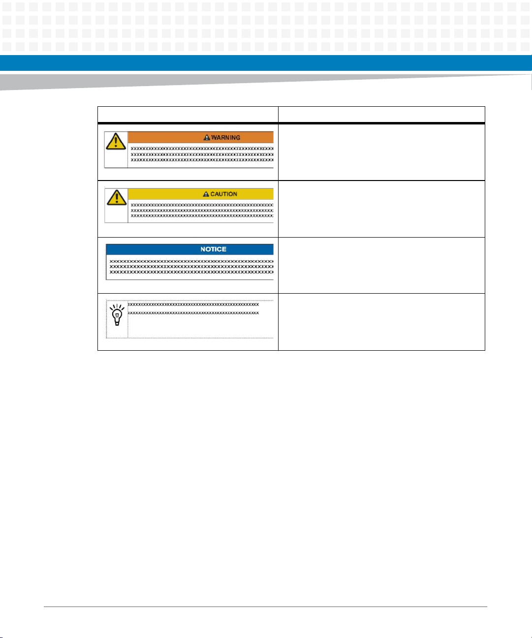
Notation Description
Indicates a hazardous situation which, if not avoided,
could result in death or serious injury
Indicates a hazardous situation which, if not avoided,
may result in minor or moderate injury
Indicates a property damage message
No danger encountered. Pay attention to important
information
About this Manual
ATCA-9305 User’s Manual (10009109-07)
35
Page 36
About this Manual
Summary of Changes
This manual has been revised and replaces all prior editions.
Part Number Publication Date Description
10009109-00 January 2009 Original release
10009109-01 April 2009 Added “GR-1089-CORE Standard” on page -i
10009109-02 July 2009 Updated Declaration of Conformity
About this Manual
Updated “Product Certification” on page 1-4
Updated section “Product Certification” on page 1-4
Updated table “Circuit Board Dimensions” on page 2-1
Updated table “Typical Power Requirements” on page 2-14
Updated table “Environmental Requirements” on page 2-14
Added “Critical Temperature Spots” on page 2-17
Updated chapter “System Management” on page 7-1
Added IPMI commands “bparams_get” on page 9-17 and
“bparams_set” on page 9-17
Updated “vlan” on page 9-26
Added inicmd to table “Standard Environment Variables” on
page 9-27
Added chapters “Safety Notes” on page 11-1 and
“Sicherheitshinweise” on page 12-1
36
10009109-03 February 2010 Updated “Boot Firmware Boot Options” on page 7-42
Updated “vlan” on page 9-26
10009109-04 August 2010 Added support for PCB Rev. 2.x
10009109-05 September 2010 Updated Declaration of Conformity
10009109-06 January 2013 Updated RoHS Compliance on page 42.
10009109-07 May 2014 Re-branded to Artesyn template.
ATCA-9305 User’s Manual (10009109-07)
Page 37

Overview
Chapter 1
The ATCA-9305 is an Advanced Telecom Computing Architecture (AdvancedTCA®, ATCA®)
blade based on dual Cavium OCTEON
MPC8548 management processor. This blade is targeted at security and packet-processing
applications in the wireless and transport market segments. These markets include data-plane
packet-processor, security co-processor, video compression, and pattern matching.
The ATCA-9305 complies with the SCOPE recommended profile for central office ATCA
systems, PICMG® 3.0 ATCA mechanical specifications, E-keying, and Hot Swap.
™
CN5860 processors and the Freescale™ Semiconductor
1.1 Components and Features
The following is a brief summary of the ATCA-9305 hardware components and features:
Cavium Processor:
The Cavium CN5860 processor is a highly programmable, high-performance 16-core
architecture operating up to 800 MHz.
Management Processor:
The Freescale PowerQUICC™ III MPC8548 processor is a 32-bit enhanced e500 core operating
at 1 GHz.
Ethernet Switch:
The Broadcom® BCM56802 is a sixteen-port, 10 GbE switch which interconnects the
processors using SPI to XAUI™ bridges. The functionality includes both 10-Gbps XAUI and 1Gbps SGMII PHY interfaces.
Stratix™ GX Bridge:
There are two packet routing Altera® SPI-4.2 high-speed interconnect to XAUI bridges per
CN5860 processor.
Ethernet:
10/100/1000BASE-T Ethernet ports are accessible via the front panel RJ45 connectors and
through the base channel on the back panel. The 10 GbE ports route to the back panel through
the fabric and RTM connectors.
ATCA-9305 User’s Manual (10009109-07)
37
Page 38

Overview
Serial Port:
The front panel serial port (MGT CSL) connects to the MPC8548 management processor. The
front panel serial port (OCT1 CSL) connects to the Cavium 1 Processor. The front panel serial
port (OCT2 CSL) connects to the Cavium 2 Processor.
System Management:
This product supports an Intelligent Platform Management Controller (IPMC) based on a
proprietary BMR-H8S-AMCc® reference design from Pigeon Point Systems. The IPMC has an
inter-integrated circuit (I2C) controller to support an Intelligent Management Platform Bus
(IPMB) that routes to the AdvancedTCA connector. The IPMB allows for features such as remote
shutdown, remote reset, payload voltage monitoring, temperature monitoring, and access to
Field Replaceable Unit (FRU) data.
PCI/PCIe:
The PCI bus allows for read/write memory access between the MPC8548 processor, Ethernet
switch, and Cavium processors. The four lane PCI Express® (PCIe) routes between the
MPC8548 and the optional RTM.
38
Real-time Clock:
The STMicroelectronics M41T00S RTC provides counters for seconds, minutes, hours, day,
date, month, years, and century. The M41T00S serial interface supports I2C bus and has a
super-cap backup capable of maintaining the clock for a minimum of two hours.
Software:
The Cavium CN5860 processor provides a GNU compiler that implements the MIPS64 Rel 2
instruction set in addition to the specialized instructions and a Linux® Board Specific Package
(BSP) including the IP-stack optimization. The CN5860 also provides libraries that take
advantage of the chip’s hardware acceleration for certain security protocols.
RTM (optional):
This blade supports a custom Rear Transition Module (RTM) with the following I/O:
Up to six 10GbE connections
One x4 PCI Express port from the MPC8548
ATCA-9305 User’s Manual (10009109-07)
Page 39

Overview
Connections for an MMC to control Hot Swap
MPC8548 console port
For more detailed information, see the ATCA-9305 Rear Transition Module User’s Manual.
ATCA-9305 User’s Manual (10009109-07)
39
Page 40
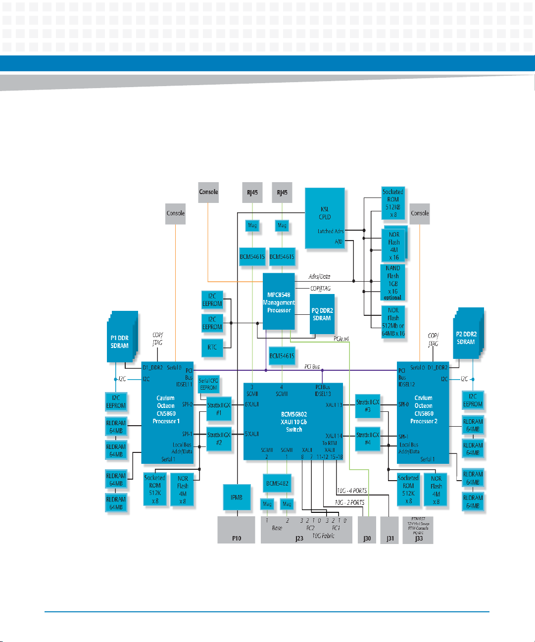
Overview
1.2 Functional Overview
The following block diagram provides a functional overview for the ATCA-9305:
Figure 1-1 General System Block Diagram
40
ATCA-9305 User’s Manual (10009109-07)
Page 41

R1 boards interface is available as PCB connector only.
1.3 Additional Information
This section lists the ATCA-9305 hardware’s regulatory certifications and briefly discusses the
terminology and notation conventions used in this manual. It also lists general technical
references.
Mean time between failures (MTBF) has been calculated at 439,924 hours using the Telcordia
SR-332, Issue 1 (Reliability Prediction for Electronic Equipment), method 2 at 30°C.
Overview
1.3.1 Product Certification
The ATCA-9305 has been tested to comply with various standards:
Table 1-1 Standard Compliance
Standard Description
UL 60950-1
EN 60950-1
IEC 60950-1
CAN/CSA C22.2 No 60950-1
CISPR 22
CISPR 24
EN 55022
EN 55024
FCC Part 15
Industry Canada ICES-003
VCCI Japan
AS/NZS CISPR 22
EN 300 386
Legal safety requirements
EMC requirements (legal) on system level (predefined
Artesyn system)
ATCA-9305 User’s Manual (10009109-07)
41
Page 42

Overview
The product has been partially tested to comply with NEBS Standard GR-1089 CORE, NEBS
Standard GR-63-CORE, ETSI EN 300019 series, and PICMG 3.0.
Artesyn maintains test reports that provide specific information regarding the methods and
equipment used in compliance testing. Unshielded external I/O cables, loose screws, or a
poorly grounded chassis may adversely affect the ATCA-9305 hardware’s ability to comply
with any of the stated specifications.
The Ethernet connection of the equipment or subassembly must be connected with shielded
cables that are grounded at both ends.
1.3.2 RoHS Compliance
The ATCA-9305 is compliant with the European Union’s RoHS (Restriction of use of Hazardous
Substances) directive created to limit harm to the environment and human health by
restricting the use of harmful substances in electrical and electronic equipment. Effective July
1, 2006, RoHS restricts the use of six substances: cadmium (Cd), mercury (Hg), hexavalent
chromium (Cr (VI)), polybrominated biphenyls (PBBs), polybrominated diphenyl ethers
(PBDEs) and lead (Pb). Configurations that are RoHS compliant are built with lead-free solder.
42
ATCA-9305 User’s Manual (10009109-07)
Page 43
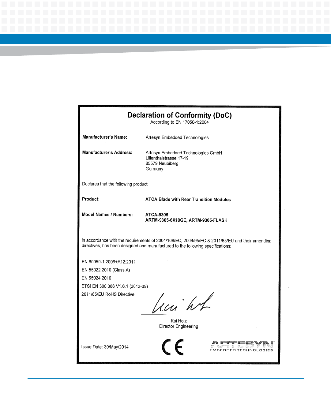
Following is the Declaration of Conformity:
Figure 1-2 Declaration of Conformity
Overview
ATCA-9305 User’s Manual (10009109-07)
43
Page 44

Overview
1.3.3 Terminology and Notation
Active low signals
An active low signal is indicated with an asterisk * after the signal name.
Byte, word
Throughout this manual byte refers to 8 bits, word refers to 16 bits, and long word refers to 32
bits, double long word refers to 64 bits.
PLD
This manual uses the acronym, PLD, as a generic term for programmable logic device (also
known as FPGA, CPLD, EPLD, etc.).
44
ATCA-9305 User’s Manual (10009109-07)
Page 45

Overview
Radix 2 and 16
Hexadecimal numbers end with a subscript 16. Binary numbers are shown with a subscript 2.
ATCA-9305 User’s Manual (10009109-07)
45
Page 46

Overview
46
ATCA-9305 User’s Manual (10009109-07)
Page 47
Setup
This chapter describes the physical layout of the boards, the setup process, and how to check
for proper operation once the boards have been installed. This chapter also includes
troubleshooting, service, and warranty information.
2.1 Electrostatic Discharge
Before you begin the setup process, please remember that electrostatic discharge (ESD) can
easily damage the components on the ATCA-9305 hardware. Electronic devices, especially
those with programmable parts, are susceptible to ESD, which can result in operational failure.
Unless you ground yourself properly, static charges can accumulate in your body and cause
ESD damage when you touch the board.
Chapter 2
Use proper static protection and handle ATCA-9305 boards only when absolutely necessary.
Always wear a wriststrap to ground your body before touching a board. Keep your body
grounded while handling the board. Hold the board by its edges—do not touch any
components or circuits. When the board is not in an enclosure, store it in a static-shielding
bag.
To ground yourself, wear a grounding wriststrap. Simply placing the board on top of a staticshielding bag does not provide any protection—place it on a grounded dissipative mat. Do not
place the board on metal or other conductive surfaces.
ATCA-9305 User’s Manual (10009109-07)
47
Page 48
Setup
2.2 ATCA-9305 Circuit Board
The ATCA-9305 circuit board is an ATCA blade assembly and complies with the PICMG 3.0 ATCA
mechanical specification. It uses a 16-layer printed circuit board with the following dimensions:
Table 2-1 Circuit Board Dimensions
Width Depth Height Weight (typical)
12.687 in.
(322.25 mm)
This is the typical weight for the ATCA-9305. Board weight varies slightly per configuration; contact
Technical Support if you require a specific configuration weight.
11.024 in.
(280.01 mm)
< .84 in.
(<21.33 mm)
4.52 lb.
(2.05 kg)
1
48
ATCA-9305 User’s Manual (10009109-07)
Page 49
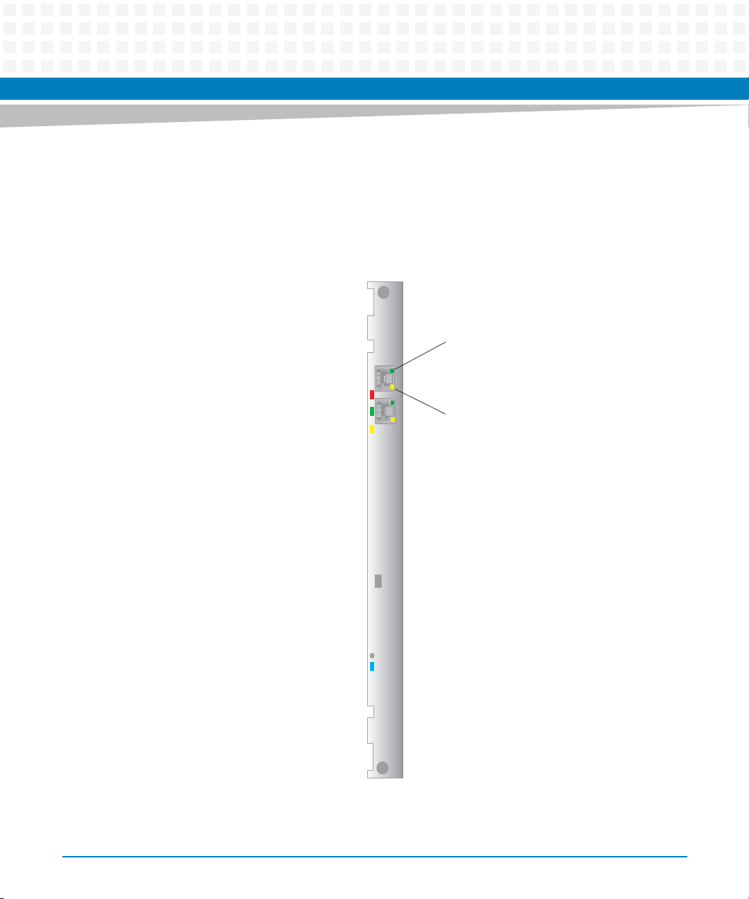
Setup
The following figures show the front panel, component maps, and LED locations for both old
ATCA-9305 (PCB Rev.1.x) board and the new ATCA-9305 (PCB Rev.2.x) board.
Figure 2-1 ATCA-9305 Front Panel (PCB Rev. 1.x)
Ethernet Speed (top LED)
Off = 10 Mbps
Yellow = 100 Mbps
Green = 1000Mbps
Ethernet Link/Activity (bottom LED)
Off = No Link
Red/Amber = Out of Service (OOS)
Green = In Service (2)
Amber = User Defined (3)
MGT ETH
LNK
Port 1
ACT
O
O
S
LNK
2
ACT
Port 2
SWITCH
3
ETH
On= Link, No Activity
Blink = Link/Activity
Management Console
ATCA-9305 User’s Manual (10009109-07)
Reset
Blue Hot Swap
MGT CSL
RST
H/S
ATCA-9035
49
Page 50
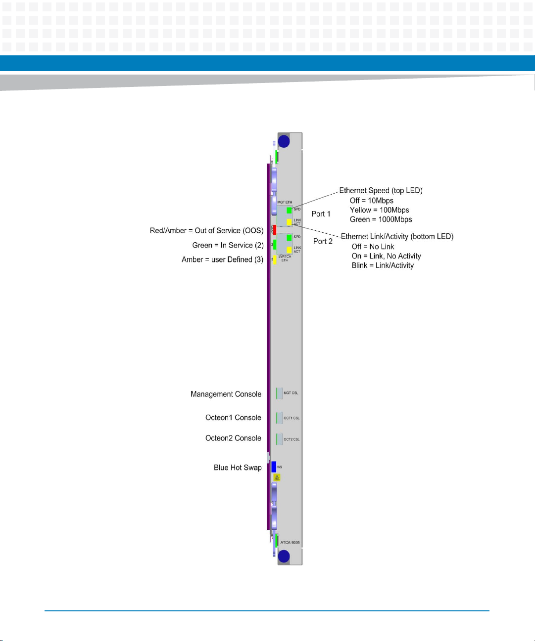
Setup
Figure 2-2 ATCA-9305 Front Panel (PCB Rev. 2.x)
50
ATCA-9305 User’s Manual (10009109-07)
Page 51
Setup
The electromagnetic compatibility (EMC) tests used an ATCA-9305 model that includes a
front panel assembly from Artesyn Embedded Technologies - Embedded Computing.
For applications where the ATCA-9305 is provided without a front panel, or where the front
panel has been removed, your system chassis/enclosure must provide the required
electromagnetic interference (EMI) shielding to maintain CE compliance.
ATCA-9305 User’s Manual (10009109-07)
51
Page 52
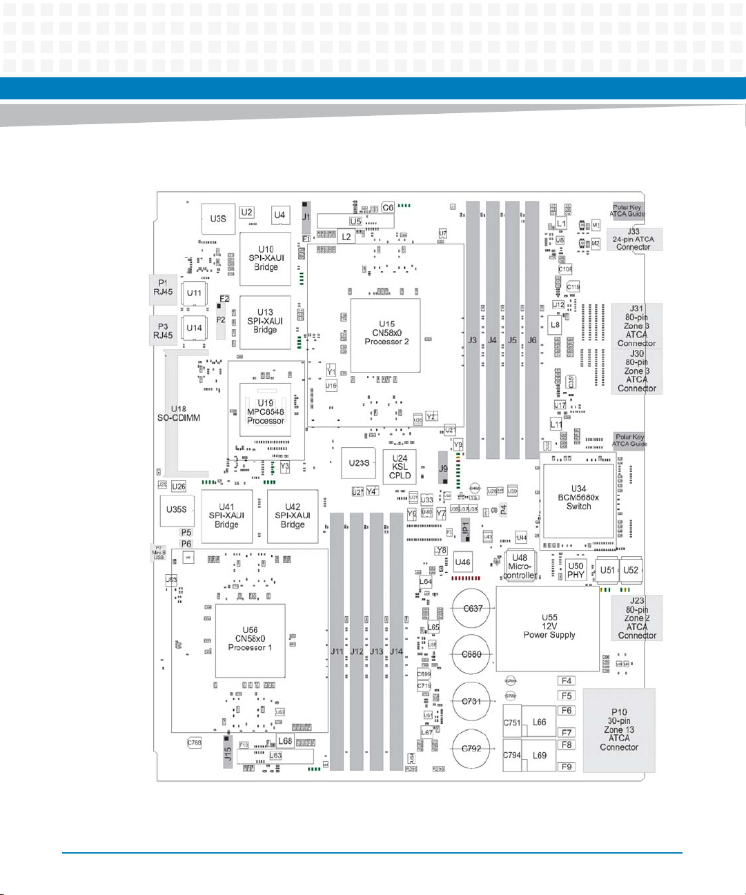
Setup
Figure 2-3 Component Map, Top (PCB Rev. 1.x)
52
ATCA-9305 User’s Manual (10009109-07)
Page 53
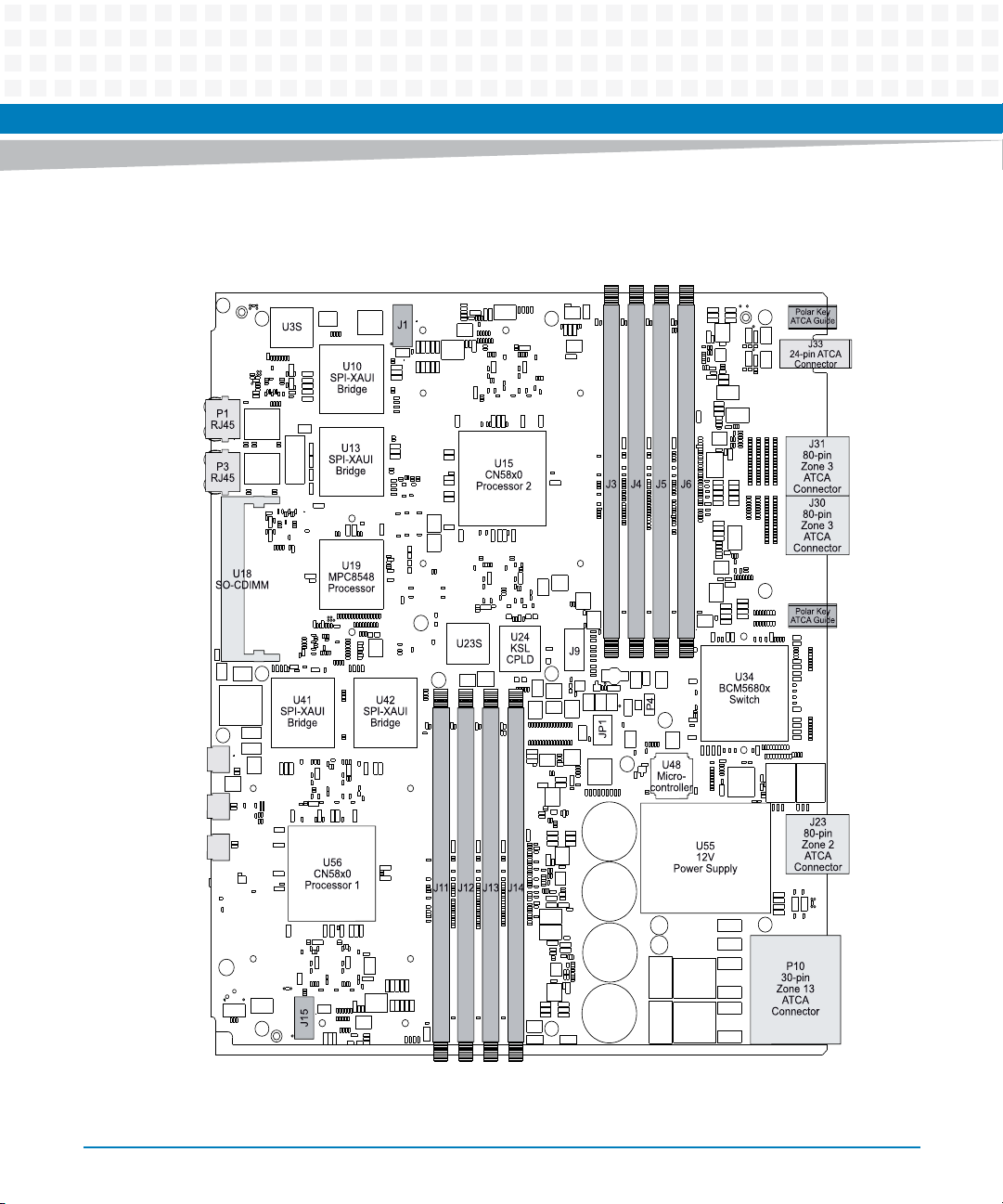
Figure 2-4 Component Map, Top (PCB Rev. 2.x)
Setup
P7
Mini-B
USB
P0800
Mini-B
USB
P0801
Mini-B
USB
ATCA-9305 User’s Manual (10009109-07)
53
Page 54
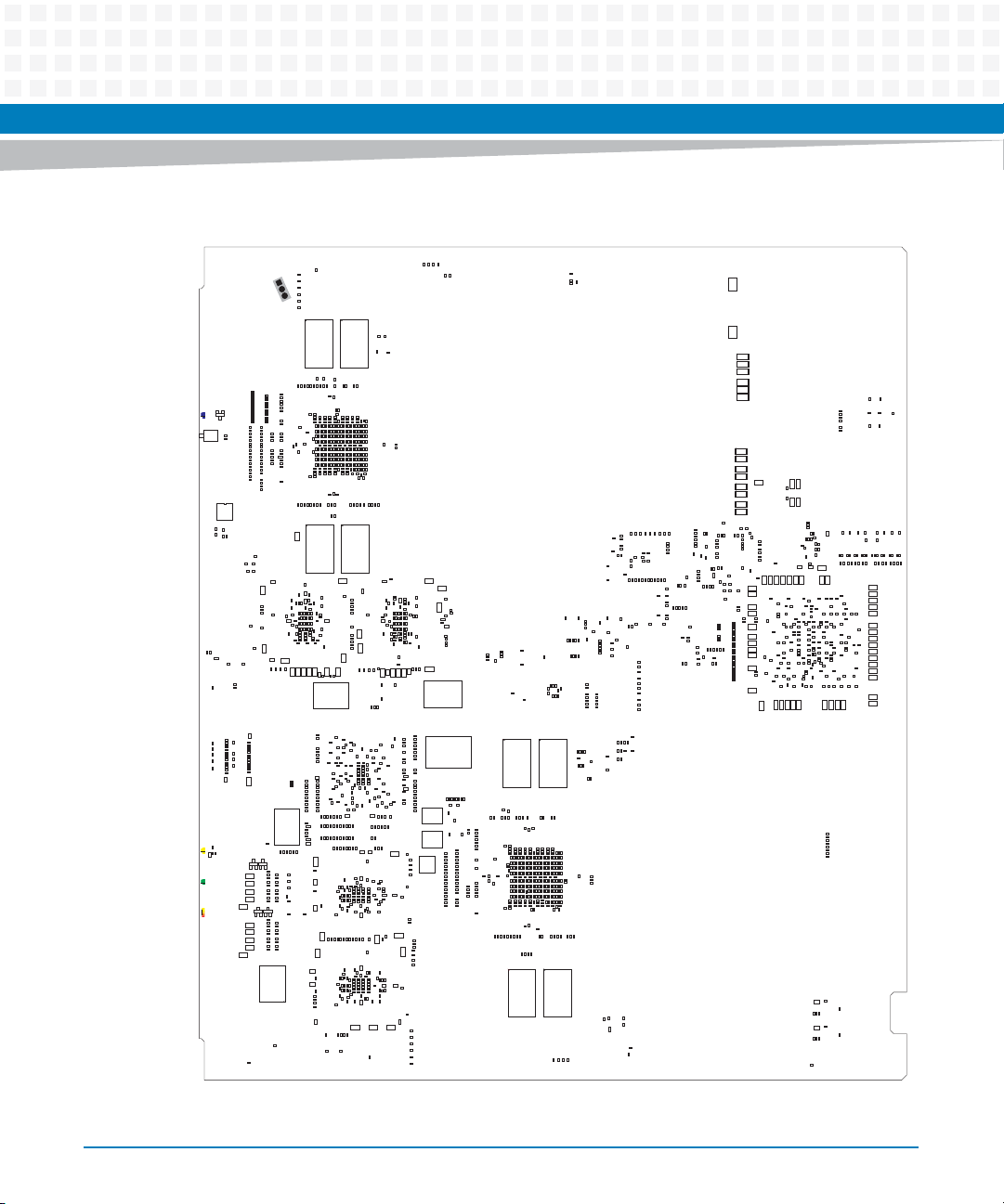
Setup
Figure 2-5 Component Map, Bottom (PCB Rev. 1.x)
R1007
R1008
R1006
C2102
R1005
J16
R1003
R1000
R999
R998
R997
U82
U81
R995
R996
R994
R981
R986
R991
R993
R992
R989
R990
R987
R983
R985
R984
R988
R980
R982
R979
RN39
RN38
R978
R976
RN37
RN35
R975
R974
RN36
R973
RN33
RN34
Q5
CR57
C2022
SW2
R951
U80
C1808
C1804
C1805
C1800
C1483
C1484
C1466
C1378
C1351
C1352
C1340
C1341
C1326
C1315
C1316
C1298
R610
C1289
C1215
R476
R477
CR56
C1197
CR55
CR54
R968
RN31
RN32
R967
R963
R965
R964
R962
R953
R959
R957
R955
R958
R952
R954
R956
R950
R948
R945
R946
R947
R949
R943
R941
R942
R940
R939
R938
R913
R932
R936
R930
R933
R931
R935
C1925
R925
R927
R923
R929
R928
R922
R926
R924
R921
R919
R917
R920
R918
R914
R916
R915
R911
R910
R908
R909
R904
R903
C1799
C1761
C1755
C1756
C1748
C1749
C2187
C2168
R778
R768
R767
R766
C1650
C2153
C1625
R747
R717
C2173
C2186
C2176
C1444
C1445
R685
R684
R683
R686
R671
R667
C1356
C1349
RN19
C1350
RN18
C1339
C1325
RN17
RN16
C1324
C1313
RN15
C1314
RN14
C1297
C1270
C1269
U71
PHY
L84
R473
R475
R474
Q4
Q3
L81
C1115
R444
R443
R445
R433
C1083
R431
R432
C1082
R434
C1051
R424
R422
R423
C1050
R412
C1017
R411
C956
R400
R410
R401
R399
C955
R398
C917
Q2
Q1
R388
L76
C893
R384
R381
C892
R380
R377
C889
R378
C888
R376
C886
R357
R358
C885
R356
R338
C884
R339
C883
R337
C882
U68
PHY
C807
R299
C2088
C2086
R977
R1018
R1017
C2082
C2080
C2075
C2081
C2076
C2072
C2079
C2073
C2071
C2074
C2078
C2077
C2054
C2057
C2059
C2061
C2051
C2053
C2068
C2066
C2063
C2048
C2049
C2058
C2047
C2056
C2060
C2050
C2064
C2052
C2062
C2067
C2065
C2055
C2026
C2027
C2045
C2031
C2034
C2040
C2037
C2035
C2044
C2030
C2036
C2041
C2039
C2029
C2038
C2028
C2033
C2032
C2043
C2042
R1047
C1923
C1878
C1840
C1839
C1838
R897
R896
C1695
C1672
C1644
C1618
C1574
C1573
C1539
C1540
C1510
C1428
C1288
L82
L79
R323
R322
R320
R319
C2015
C2017
C2019
C2021C1956
C2016
C2014
C2020
C2018
C1977
C1978
C1976
C1979
C1954
C1951
C1952
C1955
C1953
C1922
C1921
C1920
C1919
C1898
C1897
C1899
C1900
C1873
C1877
C1874
C1876
C1875
C1872
C1837
C1835
C1834
C1836
R895
R894
C1716
C1694
C2123
C1642
C1643
L94
C2151
C1572
C1537
C1538
R727
R674
L89
C1427
U77
PHY
R645
R644
R632
R631
R623
R622
R616
C1268
R603
R596
R595
R590
R589
R584
R583
R568
R567
R562
R561
R537
R536
R515
R516
C2184
L80
C916
L77
C2171
C2166
L74
L71
C2189
C2025
C1995
C2013
C2007
C2003
C2011
C2005
C1986
C2009
C1985
C2001
C1997
C1981
C1999
C1991
C1983
C1989
C1993
C1980
C1982
C1998
C2004
C1988
C2006
C2000
C1987
C2008
C1992
C2010
C2002
C1996
C2012
C1984
C1990
C1994
C1962
C1973
C1967
C1961
C1965
C1970
C1960
C1972
C1966
C1964
C1959
C1969
C1974
C1975
C1971
C1968
C1963
C1948
C1945
C1933
C1939
C1930
C1936
C1942
C1937
C1934
C1950
C1931
C1943
C1940
C1949
C1938
C1947
C1941
C1929
C1932
C1927
C1928
C1944
C1946
C1935
C1912
C1918
C1914
C1910
C1907
C1905
C1917
C1916
C1913
C1911
C1904
C1915
C1908
C1906
C1902
C1903
C1909
C1891
C1882
C1896
C1880
C1884
C1895
C1881
C1888
C1892
C1893
C1886
C1883
C1885
C1887
C1889
C1890
C1894
C1870
C1864
C1848
C1844
C1851
C1859
C1846
C1854
C1860
C1850
C1868
C1867
C1871
C1865
C1862
C1856
C1857
C1869
C1861
C1866
C1858
C1852
C1855
C1843
C1853
C1847
C1849
C1845
C1863
C1829
C1833
C1827
C1831
C1826
C1825
C1823
C1824
C1830
C1828
C1832
R912
R906
R907
R902
C1816
C1817
C1811
R893
R888
R891
R887
R890
R892
R889
R881
R882
U78
C2185
C2192
R758
R782
R777
R776
R764
R763
R762
R746
R738
R737
C2181
R726
R725
R716
C2178
C2174
R681
R682
L88
L87
C1425
C1426
C1355
C1347
C1345
C1348
C1344
C1346
C1337
C1336
C1333
C1334
C1338
C1335
C1322
C1321
C1323
C1312
C1309
C1305
C1311
C1303
C1302
C1310
C1306
C1307
C1308
C1304
C1293
C1295
C1292
C1296
C1294
C1287
C1284
C1279
C1276
C1275
C1285
C1282
C1277
C1280
C1274
C1286
C1281
C1283
C1278
C1258
C1267
C1262
C1260
C1265
C1266
C1263
C1259
C1261
C1264
C1255
C1252
C1253
C1254
C1256
C1244
C1246
C1247
C1245
C1240
C1238
C1236
C1239
C1237
C1229
C1228
R1022
R1021
C1225
R557
R559
R558
R556
R560
R530
R529
R533
R534
R528
R535
R527
R532
R531
R513
R511
R512
R508
R506
R507
R509
R514
R510
R490
R492
R488
R489
R487
R491
R493
R486
C2193
C2188
R461
C1080
C1081
C2159
R1030
C1079
L83
C2129
C1042
C1048
C1049
C1046
C1044
C1043
C1041
C1040
C1045
C1047
C1009
C1006
C1016
C1002
C1005
C1003
C1010
C1007
C1001
C1015
C1014
C1013
C1012
C1004
C1011
C1000
C1008
C954
C942
C945
C947
C948
C950
C952
C953
C951
C949
C943
C946
C944
C912
L105
C915
C913
C914
C2131
C911
C897
C896
C895
R386
C2161
R346
R353
R349
R348
R352
R355
R344
R351
R350
R347
R345
R354
R333
C2162
C880
C879
C878
R1031
C881
L107
C2135
C866
C873
C874
C864
C875
C872
C870
C868
C862
C871
C865
C863
C869
C867
C849
C853
C859
C851
C846
C856
C854
C855
C857
C848
C847
C852
C850
C858
C832
C836
C834
C831
C840
C841
C842
C833
C839
C830
C837
C835
C838
L70
C829
C826
C828
C824
C2133
C827
C825
C2164
R318
C2170
C2167
R311
R314
R313
R310
R312
C805
C804
C2046
R934
R944
R1037
C1957
C1924
C1841
R900
R901
R899
R898
C1798
U79
L97
C2150
C1717
C1719
C1720
C2122
C2152
C1697
C2124
C1698
C1696
L102
C1699
C1718
C1674
C1676
C1673
C1677
C1675
R1028
C1646
C1647
C1648
C1645
C1649
L101
C1619
C1621
C1620
C1623
C1622
C1624
C2121
C1576
C1579
C1580
C1577
C1582
C1578
C1581
C1575
C1583
C1584
C1547
C1543
C1541
C1546
C1542
C1544
C1545
C1548
C1512
C1511
C1431
C1429
C1430
R605
RN13
R604
R598
R597
R592
R591
R586
R585
R570
R569
R539
C1221
L86
R517
L85
C1217
C1216
R471
R472
R470
R387
L75
L72
R1009
R1004
C2101
C2096
C2099
C2094
C2095
R937
C1958
C1926
R886
R885
R883
R884
L96
C2154
C2180
C2179
C1714
C1711
R781
C1712
C2126
C1715
C2128
C2156
C1689
C1691
C1692
C1690
C1688
L104
C1693
C1713
R1015
R1016
C2172
C1667
C1668
C1670
C1669
C1671
C1666
R1029
C2127
R756
C1634
C1633
C1641
C2155
L92
R679
R680
C1395
R663
R651
R649
R650
C1343
C1332
C1331
C1319
C1320
C1301
C1300
C1290
C1291
C1273
C1257
C1251
C1250
C1242
C1243
C1235
C1234
C1227
C1224
R555
R554
R526
R524
R525
R523
R505
R504
R483
R484
R485
C1076
C1078
C1077
C1039
C2132
C999
L78
C2158
C941
C940
C2130
C910
C894
R342
R341
C2183
C877
C876
C861
C860
C2134
L108
C2163
C845
C2136
C822
C821
C823
C802
C2157
C1637
C1640
C1636
C1635
C1639
C1638
L95
L103
C1615
C1611
C1614
C1616
C1613
C1612
C1617
C1571
L91
C1424
C1299
C1241
C1226
R553
R521
R522
C2177
R343
C843
C844
C2182
C2125
C1536
C1233
R552
C1569
C1568
C1570
C1535
C1534
C1509
C1423
C1354
C1342
C1232
C2160
C2175
C2165
C1566
C1567
C1565
C1533
C1531
C1532
C1465
L93
C1422
R670
C2190
C1562
C1564
C1560
C1561
C1563
C1558
C1559
C1529
C1530
C1508
C1507
C1506
R678
L90
C1421
R642
R641
R643
R638
R640
R639
R637
R629
R630
R628
R620
R621
R619
R615
R608
R609
R606
C1272
C1271
R602
R600
R599
R601
R594
C1248
R593
C1249
R588
R587
R582
R580
R581
R579
R566
R565
R469
R459
R453
R452
R442
R421
L106
R383
R382
R340
R336
R335
R331
R330
C2169
R325
R324
L73
R316
R309
R307
R306
R305
R304
R298
C1528
R724
C1420
R676
R677
U76
StrataFlash
U75
NAND
Flash
U72
U70
U69
C2191
R736
R735
R723
R722
R715
R714
R704
R701
R703
R702
C1464
C1377
U74
R573
R575
R574
R578
R572
R577
R571
R576
C1231
C1230
R564
C1223
R503
R468
R467
R458
R457
R451
R450
R441
R440
R430
R429
R420
R419
R409
R408
R397
R396
R393
R563
R547
R549
R550
R551
R548
R538
R520
R519
R502
R501
C1218
R500
R497
R496
R481
C1214
C1213
C1212
R480
R482
C1196
R466
R465
R456
R455
R449
R406
R439
R438
R428
R427
R418
R417
R407
R395
R394
R392
C1192
C1195
C1191
C1194
C1159
R454
C1158
R446
R1048
R447
C1136
C1137
C1114
R436
R1038
R448
R437
C1112
C1073
C1075
R426
C1074
R416
R414
C1038
R415
R413
C998
R405
R403
R402
R404
C997
C939
C937
C938
C936
C908
C906
C909
C907
R385
R373
R370
R372
R371
R375
R374
U67
C2100
R1002
R1001
C1632
R734
R733
C1482
R700
R692
C1392
C1393
C1394
C1375
C1373
C1374
C1376
C1371
C1370
C1369
R662
U73
R542
R543
R541
R544
R540
R545
R546
C1222
C1220
C1219
R518
C1210
C1205
C1209
C1207
C1203
C1201
C1198
C1211
C1202
C1208
C1199
C1204
C1206
C1200
C1187
C1162
C1179
C1165
C1161
C1181
C1176
C1173
C1184
C1167
C1170
C1188
C1189
C1174
C1193
C1182
C1183
C1178
C1171
C1163
C1172
C1190
C1185
C1177
C1180
C1175
C1186
C1160
C1168
C1169
C1164
C1166
C1153
C1142
C1138
C1146
C1152
C1157
C1141
C1143
C1154
C1150
C1139
C1149
C1144
C1148
C1151
C1140
C1155
C1156
C1147
C1145
C1118
C1124
C1125
C1120
C1123
C1133
C1128C982
C1129
C1135
C1117
C1130
C1121
C1122
C1131
C1119
C1134
C1132
C1126
C1127
C1116
C1090
C1102
C1087
C1108
C1107
C1089
C1110
C1111
C1098
C1099
C1101
C1105
C1104
C1093
C1092
C1085
C1086
C1096
C1095
C1113
C1106
C1103
C1109
C1097
C1094
C1091
C1088
C1100
R1013
C1061
C1057
C1056
C1071
C1062
C1066
C1060
C1065
C1064
C1070
C1069
C1072
C1058
C1059
C1063
C1068
C1055
C1054
C1053
C1067
R1014
C1018
C1035
C1032
C1030
C1026
C1028
C1033
C1034
C1024
C1031
C1029
C1023
C1019
C1027
C1037
C1025
C1020
C1036
C1022
C1021
C958
C974
C988
C966
C990
C984
C994
C970
C967
C978
C976
C972
C960
C996
C964
C962
C992
C986
C969
C981
C987
C995
C957
C985
C983
C991
C961
C973
C979 C980
C975
C968
C971
C963
C965
C989
C993
C977
C959
C933
C935
C925
C928
C931
C924
C918
C920
C922
C921
C919
C923
C929
C927
C932
C930
C934
C926
C901
C904
C900
C899
C902
C905
C903
C898
R390
R389
R391
R1019
R1020
R379
C891
C890
R369
R367
R361
R368
R363
R362
R364
R360
R365
R366
C887
R328
R329
R327
R326
U66
R301
R303
R300
R302
C2098
C2097
C2093
C2092
C2091
C2090
C2089
C2087
C2085
C1901
C1879
C1842
C1822
R905
C1821
C1820
C1819
C1815
C1810
C1809
R880
R879
R867
R866
R870
R876
R874
R873
R875
R871
R869
R868
R872
R1055
R877
R852
R851
R845
R844
C1784
C1782
C1783
R1045
R1044
R1051
R1052
C1759
C1760
R1053
R825
R1054
R802
C1743
R800
R801
R798
R797
R799
R795
R796
R755
C1631
R753
R754
C1610
R745
R744
R1033
C1526
R731
R732
C1527
R698
R696
R699
R697
R669
R666
R661
R660
R656
R655
R648
R625
R626
R624
R627
C1318
R611
R614
R612
R613
R1011
R1012
R435
C1084
C1052
R425
R359
C1608
C1609
R742
R743
R739
R730
C1525
R719
R721
R720
C1481
C1505
R711
R713
R712
R695
R691
R690
R675
R673
R668
R665
R664
R659
R658
R657
R654
R653
R652
R647
R646
C1353
R636
R635
R634
R633
C1327
C1328
C1329
C1330
C1317
R617
R618
R607
C815
C814
C816
C813
C811
C806
C803
R1058
R862
R865
R863
R864
R1043
R850
C1803
R849
R847
R848
R843
R842
R834
R833
R789
R791
R794
R793
R792
R790
R787
R788
C1731
R784
R780
R779
R775
R774
R770
R773
R771
R769
R772
R751
R752
R750
C1607
R729
R689
C1443
R836
R841
R838
C1790
R840
R837
R839
C1789
R832
R829
C1781
C1758
R828
R822
R821
R823
R824
C1754
C1747
C1746
R1046
C1745
C1742
C1741
R1040
C1727
C1728
R785
R786
C1729
C1730
C1723
C1724
R783
C1710
C1687
C1665
R749
R741
RN29
C1606
RN30
RN28
C1524
RN27
RN26
R728
RN25
C1504
R705
R709
R706
R707
R708
C1480
RN24
R710
R693
C1463
R694
RN23
C1442
R688
R687
RN22
RN21
RN20
C1818
C1814
C1812
C1813
L100
C1807
R878
R1042
C1744
C1726
C1722
C1686
C1664
C1605
C1523
C1503
C1479
C1462
C1419
C1372
C1806
C1802
C1801
C1797
R122
R748
R740
C1418
C1407
C1793
C1795
C1796
C1794
R846
R835
R831
R830
R827
R826
C1785
C1786
C1788
C1787
C1779
C1778
C1780
C1757
R820
C1752
C1753
C1751
C1750
C1739
C1733
C1737
C1740
C1736
C1735
C1738
C1734
C1705
C1707
C1709
C1708
C1706
C1685
C1682
C1684
C1681
C1683
C1659
R760
C1660
C1661
C1663
C1658
C1662
C1629
C1627
C1628
C1630
C1594
C1592
C1599
C1596
C1598
C1604
C1597
C1591
C1601
C1593
C1595
C1603
C1602
C1600
C1553
C1554
C1552
C1556
C1557
C1551
C1555
C1521
C1518
C1516
C1517
C1522
C1520
C1519
C1494
C1497
C1500
C1501
C1502
C1498
C1499
C1496
C1495
C1474
C1477
C1475
C1473
C1472
C1478
C1476
R1027
R1026
C1454
C1459
C1457
C1461
C1452
C1458
C1456
C1460
C1453
C1455
C1435
C1441
C1437
C1439
C1438
C1434
C1440
C1436
C1433
C1415
C1416
C1412
C1413
C1411
C1414
C1417
C1405
R672
C1406
C1403
C1401
C1402
C1404
C1391
C1387
C1389
C1384
C1386
C1390
C1385
C1388
C1363
C1362
C1366
C1365
C1364
C1367
R321
C820
C818
C817
C819
R315
C812
C810
C809
C808
R297
C2083
C2084
R972
C2069
C2070
R971
R969
R970
R966
C2023
C2024
R961
R960
R857
R853
R859
R855
R854
R856
R860
R858
R861
C1791
C1792
L99
L98
C1762
C1773
C1768
C1774
C1776
C1766
C1767
C1765
C1772
C1777
R818
C1732
C1701
C1703
C1702
C1704
C1680
C1656
C1657
C1589
C1588
C1586
C1590
C1587
C1515
C1492
R718
C1493
C1491
C1490
C1470
C1471
C1450
C1447
C1449
C1451
C1448
C1410
C1400
C1399
C1383
C1382
C1381
C1361
C1359
C1360
R499
R498
R495
R494
R479
R478
R464
R463
R317
R308
C1763
C1769
C1775
C1764
C1771
C1770
R807
R805
R809
R810
R812
R811
R808
R813
R803
R804
R814
R806
R816
R815
R817
C1725
C1721
C1700
C1679
C1678
C1654
C1652
C1653
C1655
C1651
C1626
C1585
C1550
C1549
C1514
C1513
C1488
C1487
C1486
C1485
C1489
C1469
C1467
C1468
C1446
C1432
C1409
C1408
C1397
C1398
C1396
C1379
C1380
C1368
C1357
C1358
54
ATCA-9305 User’s Manual (10009109-07)
Page 55
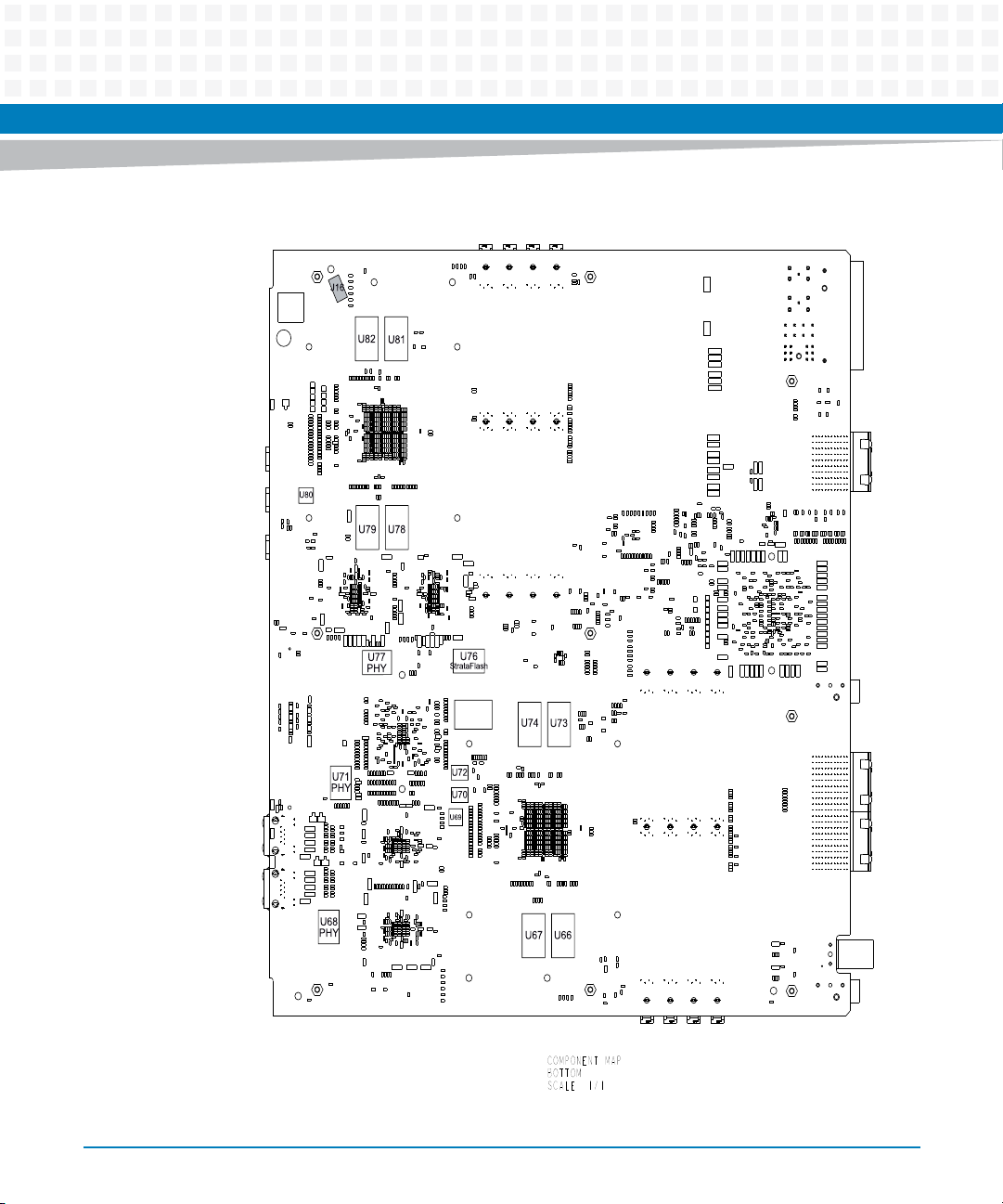
Figure 2-6 Component Map, Bottom (PCB Rev. 2.x)
Setup
ATCA-9305 User’s Manual (10009109-07)
U75
NAND
Flash
optional
COMPONENT MAP
BOTTOM
SCALE 1/1
55
Page 56
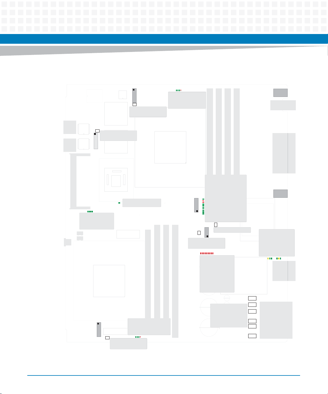
Setup
Figure 2-7 LED, Fuse and Switch Locations, Top (PCB Rev. 1.x)
CR1
CR4
CR2
CR3
CR1 - P2_LED_GPIO12-R
CR2 - P2_LED_GPIO13-R
CR3 - P2_LED_GPIO14-R
CR4 - P2_LED_GPIO15-R
J9
F3
F3 - .75 Amp Fuse
(self resetting)
MPC8548
CR13 - PQ_GREENLED_R*
CR14 - PQ_CKSTP_OUT_R*
CR16 - PQ_REDLED_R*
Debug
CR18 - DEBUG_LED1_R*
CR13
CR19 - DEBUG_LED2_R*
CR14
CR16
CR21 - DEBUG_LED3_R*
CR18
CR19
CR22 - DEBUG_LED43_R*
CR21
CR22
Boot Device
CR31
CR32
CR31 - FL0_LED_R*
CR33
CR32 - FL1_LED_R*
CR33 - SKT_LED_R*
JP1
CR37
CR41
CR36
CR35
CR40
CR38
CR39
IPMP State
CR35 - STATE_LED8
CR36 - STATE_LED7
CR37 - STATE_LED6
CR38 - STATE_LED5
CR39 - STATE_LED4
CR40 - STATE_LED3
CR41 - STATE_LED2
CR42 - STATE_LED1
CR43 - STATE_LED0
F4 - 1 Amp Fuse
F5 - 1 Amp Fuse
F6 - 10 Amp Fuse
F7 - 8 Amp Fuse
F8 - 10 Amp Fuse
F9 - 8 Amp Fuse
F2
F2 - .75 Amp Fuse
(self resetting)
P2
CR25
CR26
CR24
CR23
CR23 - MIP1_LED1_R
CR24 - MIP1_LED2_R
CR25 - MIP1_LED3_R
CR26 - MIP1_LED4_R
J15
F10
F1 - .75 Amp Fuse
(self resetting)
Ethernet
CR15
CR15 - TSEC2_ACTIVITY
CR50 - P1_LED_GPIO12_R1
CR51 - P1_LED_GPIO13_R1
CR52 - P1_LED_GPIO14_R1
CR53 - P1_LED_GPIO15_R1
F10 - .75 Amp Fuse
(self resetting)
J1
F1
CR51
CR50
CR52
CR53
SW1
SW1 - IPMC Reset
CR42
CR43
+
+
+
+
Ethernet
CR44 - BC1_LINKSPD1/2
CR45 - BC1_LINKSPD1/2
CR46 - BC1_ACT*
CR47 - BC2_LINKSPD1/2
CR48 - BC2_LINKSPD1/2
CR49 - BC2_ACT*
CR44
F4
F5
F6
F7
F8
F9
CR48
CR47
CR49
CR46
CR45
56
ATCA-9305 User’s Manual (10009109-07)
Page 57
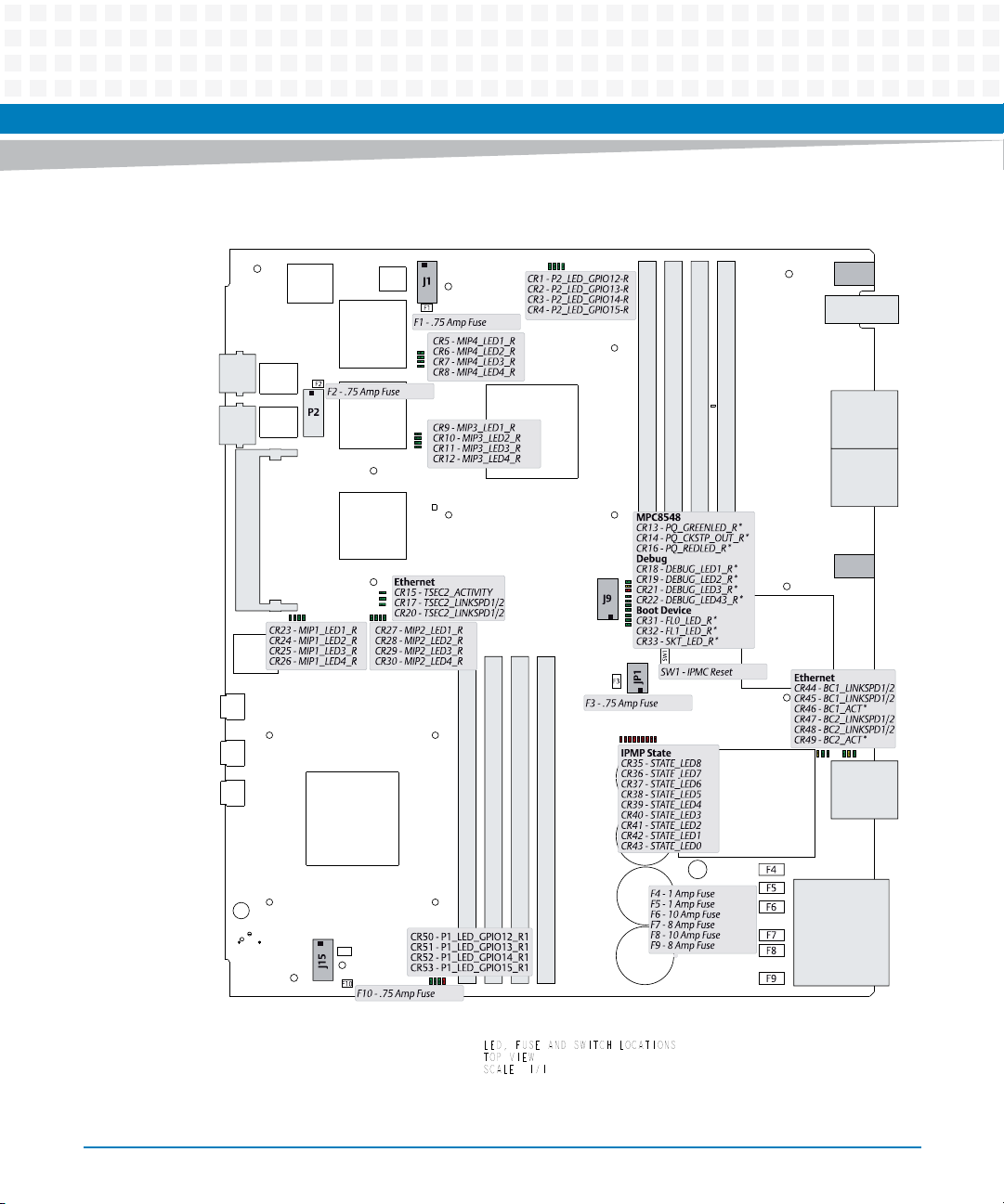
Figure 2-8 LED, Fuse and Switch Locations, Top (PCB Rev. 2.x)
Setup
ATCA-9305 User’s Manual (10009109-07)
LED, FUSE AND SWITCH LOCATIONS
TOP VIEW
SCALE 1/1
57
Page 58
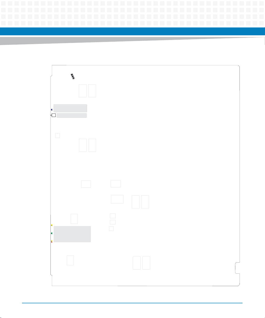
Setup
Figure 2-9 LED and Switch Locations, Bottom (PCB Rev. 1.x)
J16
Hot Swap
CR57 - BLUE_LED_CONN_K
SW2
SW2 - Front Panel Reset
58
CR56 CR57
Front Panel
CR54 - Red = LED1R_CONN
CR55
Amber = LED1A_CONN
CR55 - LED2_CONN
CR56 - LED3_CONN
CR54
ATCA-9305 User’s Manual (10009109-07)
Page 59
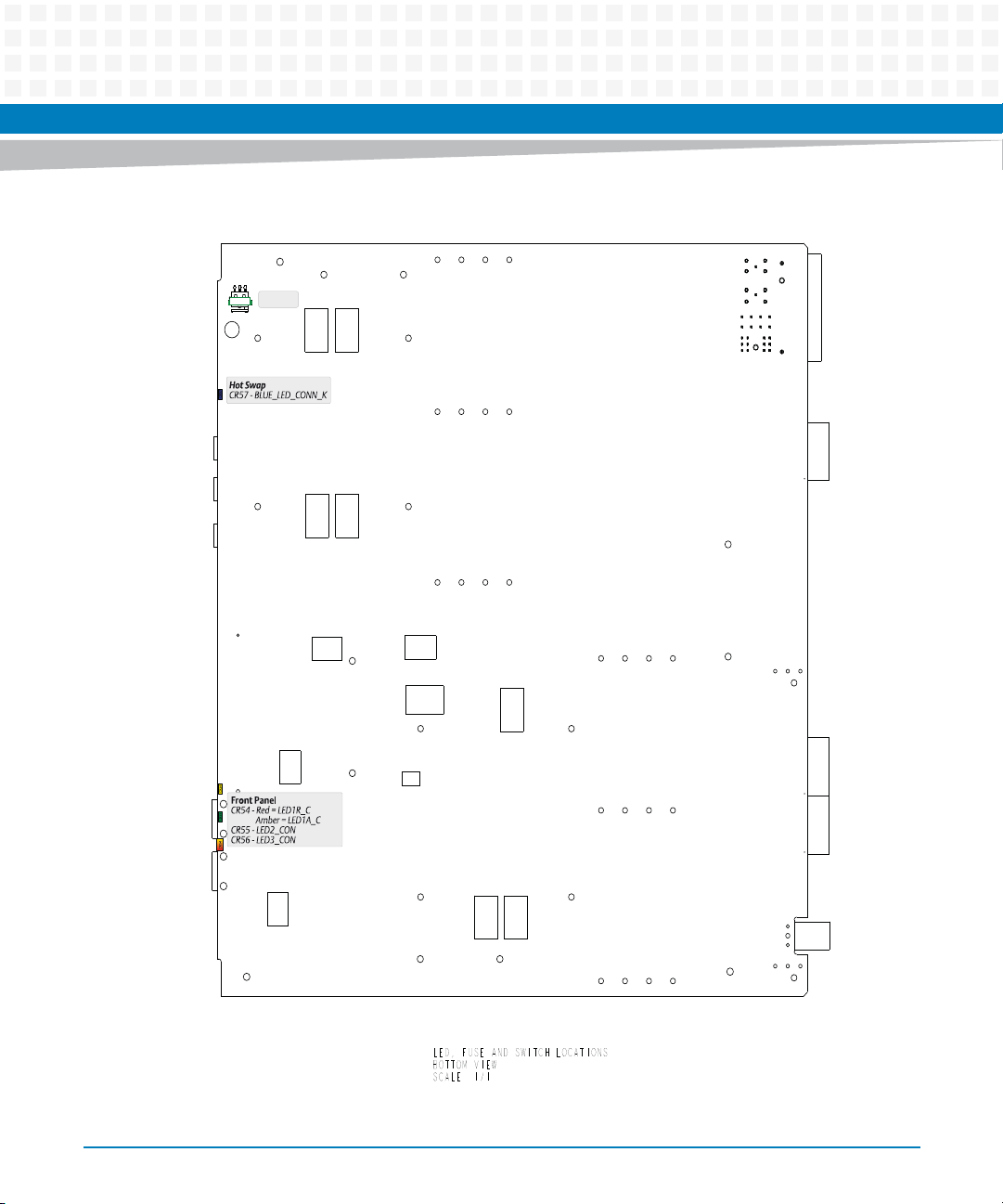
Figure 2-10 LED and Switch Locations, Bottom (PCB Rev. 2.x)
SW 4700SW 4700
Setup
ATCA-9305 User’s Manual (10009109-07)
LED, FUSE AND SWITCH LOCATIONS
BOTTOM VIEW
SCALE 1/1
59
Page 60

Setup
2.2.1 Connectors
The ATCA-9305 circuit board has various connectors and headers (see the figures beginning on
Page 52), summarized as follows:
J1: This 14-pin JTAG header is used for debugging CN5860 processor 2. See Table 3-17.
J3-J6: These 240-pin sockets are installed for the CN5860 processor 1 DDR2 SDRAM memory.
J9: This 14-pin configuration header allows selection of boot device, and MPC8548
configuration for the configuration SROM. See Figure 2-11.
J11-J14: These 240-pin sockets are installed for the CN5860 processor 2 DDR2 SDRAM
memory.
J15: This 14-pin JTAG header is used for debugging CN5860 processor 1. See Table 3-17.
J23: The 80-pin Zone 2 connector provides 1 GB and 10 GB Ethernet access to the backplane.
See Table 8-2.
60
J30-J31: The 80-pin Zone 3 connectors route PCIe and XAUI (10G) to the optional RTM. See
Table 8-3 and Table 8-4 for pin assignments.
J33: The 24-pin Zone 3 connector routes the reset, Hot Swap, MPC8548 console, power, and
IPMC I2C to the optional RTM, see Table 8-5.
JP1: This is the 10-pin programming header for the IPMP, CPLD, and SPI 10G (1-4) devices. See
Table 7-52.
P1: This 14-pin RJ45 connector with LEDs routes the Three-speed Ethernet Controller (TSEC1)
between the MPC8548 and the front panel. See Table 6-4 for pin assignments.
P2: This 16-pin JTAG debug header accesses the MPC8548 processor, see Table 4-7.
P3: This 14-pin RJ45 connector with LEDs routes Ethernet (FP1) between the switch and the
front panel, See Table 6-4 for pin assignments.
P4: The 5-pin vertical mini-B USB provides the IPMP EIA-232 console debug, see Table 7-53.
P7: This 5-pin mini-B USB is the console serial port for the MPC8548 management processor,
see Table 4-8.
P10: The 30-pin Zone 1 connector routes IPMB to the backplane, see Table 8-1.
ATCA-9305 User’s Manual (10009109-07)
Page 61
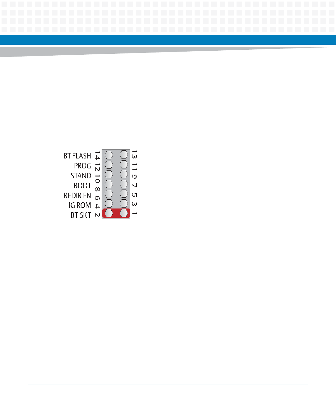
P0800, P0801: These 5 pin horizontal mini-B USBs are the CN5860 consoles which are valid for
PCB Rev. 2.x boards.
2.2.2 Configuration Header
There are a total of seven jumper pairs on J9 (pins 11-14 are spare posts). See Figure 2-3 for the
jumper location on the ATCA-9305. Also reference the “Jumper Settings (0x18)” register.
Figure 2-11 Configuration Header, J9
Setup
BT SKT: A shunt on pins 1-2 selects the 512 KB socketed ROM as the boot device for the
MPC8548.
IG SROM: If the serial ROM configuration jumper is installed (pins 3-4), the ATCA-9305 will not
try to configure (IGNORE_SROM*) from the MPC8548 serial ROM.
REDIR EN: A shunt installed on pins 5-6 disables the boot redirection, see Page 194 for more
information.
BOOT: A shunt on pins 7-8 causes both Cavium CN5860s to boot from their local bus and not
boot over PCI.
STAND: A shunt on pins 9-10, IPMC stand alone mode, allows the board to boot without
management control.
PROG: Installing a shunt on pins 11-12 puts the IPMC controller into programming mode. This
is only used in the factory to configure the IPMC.
ATCA-9305 User’s Manual (10009109-07)
61
Page 62

Setup
BT FLASH: If BOOT shunt is installed (booting from local bus), this shunt determines whether
the boot is from local flash or socket. When this BT FLASH shunt is installed, the ATCA-9305
boots from flash. Otherwise, it boots from the socket.
2.3 ATCA-9305 Setup
You need the following items to set up and check the operation of the Artesyn ATCA-9305:
ATCA chassis and power supply
MPC8548 Console cable for EIA-232 port, Artesyn part # C0007662-00
Computer terminal
Save the antistatic bag and box for future shipping or storage.
2.3.1 Power Requirements
62
Make sure that the blade is used in an AdvancedTCA shelf connected to —48 VDC up to —60
VDC, according to Telecommunication Network Voltage (TNV-2). A TNV-2 circuit is a circuit
whose normal operating voltages exceed the limits for a safety-extra-low-voltage (SELV) under
normal operating conditions, and which is not subject to over-voltages from
telecommunication networks.
Table 2-2 Typical Power Requirements
Configuration Power
1.0 GHz MPC8548 and 800 MHz Cavium processors, board running at
room temperature with all processors at U-Boot prompt
RTM-ATCA-9305 I/O 30 W
Rated Voltage —48 VDC to —60 VDC
Operating Voltage —40 VDC to —72 VDC
ATCA-9305 User’s Manual (10009109-07)
165 W
US and Canada: —48 VDC
US and Canada: —48 VDC
Page 63

The exact power requirements for the ATCA-9305 circuit board depend upon the specific
configuration of the board, including the CPU frequency and amount of memory installed on
the board. Please contact Artesyn Technical Support at 1-888-412-7832 if you have specific
questions regarding the board’s power requirements.
2.3.2 Environmental Considerations
As with any printed circuit board, be sure that air flow to the board is adequate. Chassis
constraints and other factors greatly affect the air flow rate. The environmental requirements
are as follows:
Table 2-3 Environmental Requirements
Requirement Operating Non-Operating
Setup
Temperature +5 ºC (+41 °F) to +40 ºC (+104 °F)
(normal operation) according to NEBS
Standard GR-63-CORE
-5 ºC (+23 °F) to +55 ºC (+131 °F)
(exceptional operation) according to
NEBS Standard GR-63-CORE
Airflow The blade is designed to operate in a
chassis that provides 35 CFM across the
blade for the stated temperature range.
Temp. change +/- 0.5 ºC/min according to NEBS
Standard GR-63-CORE
Rel. humidity 5% to 90% non-condensing according to
Artesyn-internal environmental
requirements
Vibration 1 g from 5 to 100 Hz and back to 5 Hz at
a rate of 0.1 octave/minute
Shock Half-sine, 11 m/Sec, 30 mSec/sec
Free fall 1,200 mm/all edges and corners
2
-40 ºC (-40 °F) to +70 ºC (+158 °F)
(may be further limited by installed
accessories)
-
+/- 0.5 ºC/min
5% to 95% non-condensing
according to Artesyn-internal
environmental requirements
5-20 Hz at 0.1 g
20-200 Hz at -3.0 dB/octave
Random 20-200 Hz at -3 m/Sec
Blade level packaging
Half-sine, 6 mSec at 180 m/Sec
1.0 m (packaged)
100 mm (unpacked)
2
/Hz
2
2
ATCA-9305 User’s Manual (10009109-07)
63
Page 64
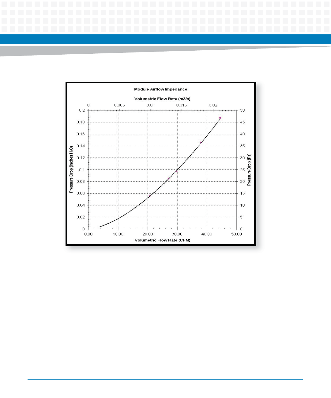
Setup
Figure 2-12 Air Flow Graph
64
During the safety qualification of this blade, the following on-board locations were identified
as critical with regards to the maximum temperature during blade operation. To guarantee
proper blade operation and to ensure safety, you have to make sure that the temperatures at
the locations specified in the following are not exceeded. If not stated otherwise, the
temperatures should be measured by placing a sensor exactly at the given locations. For your
convenience all temperature spots are shown in the figure below that provides a detailed view
of the blade.
ATCA-9305 User’s Manual (10009109-07)
Page 65
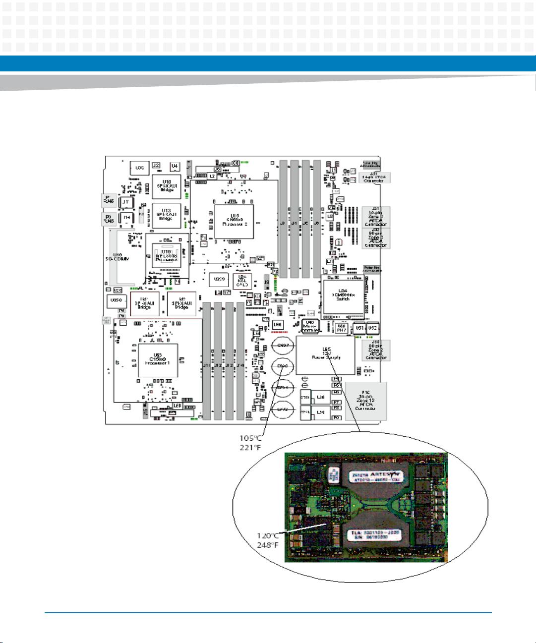
Figure 2-13 Critical Temperature Spots
Setup
ATCA-9305 User’s Manual (10009109-07)
65
Page 66
Setup
2.3.3 Hot Swap
The ATCA-9305 can be Hot Swapped, as defined in the AdvancedTCA specification (see
reference in Table A-2). This section describes how to insert and extract an ATCA-9305 module
in a typical AdvancedTCA system. (These procedures assume the system is using a shelf
manager.)
The ATCA-9305 Rear Transition Module (RTM) has its own Hot Swap LED and switch, and it
can be Hot Swapped in/out independently of the front board. If the front board is not present,
then the RTM will not be powered. If the front board is Hot Swapped out, the RTM’s blue LED
will illuminate. In either case, the RTM can be safely removed.
Personal Injury or Product Damage
66
The product is supplied by a TNV-2 voltage. This voltage is considered hazardous. Make sure
that the external power supply meets the relevant safety standards.
Make sure that TNV-2 is separated from dangerous voltages (mains) through double or
reinforced insulation.
Insert a board
1. Insert the ATCA-9305 into an available slot.
2. Push in the front panel handle (tab).
The blue Hot Swap LED on the front panel (see Figure 2-1) flashes a long blink to indicate that
board insertion is in progress and system management software is ac tivating the slot. Then the
blue LED turns off, indicating the insertion process is complete, and payload power is present.
ATCA-9305 User’s Manual (10009109-07)
Page 67
Remove a board
1. Pull out the handle (tab) on the ATCA-9305 front panel one click.
A short blink indicates the board is requesting permission for extraction.
2. Remove the board when the blue LED on the front panel is on (no payload power).
Do not remove the ATCA-9305 while the blue LED is blinking.
2.4 Troubleshooting
In case of difficulty, use the following checklist:
Setup
Be sure the ATCA-9305 circuit board is seated firmly in the carrier.
Be sure the system is not overheating.
Check the cables and connectors to be certain they are secure.
Check that your terminal is connected to a console port.
2.4.1 Technical Support
If you need help resolving a problem with your ATCA-9305, visit www.artesyn.com. Please have
the following information handy:
ATCA-9305 serial number identification (see Figure 2-14)
MPC8548 monitor version number (see Figure 9-1).
Cavium monitor version number (see Figure 3-3).
Version and part number of the operating system (if applicable)
ATCA-9305 User’s Manual (10009109-07)
67
Page 68
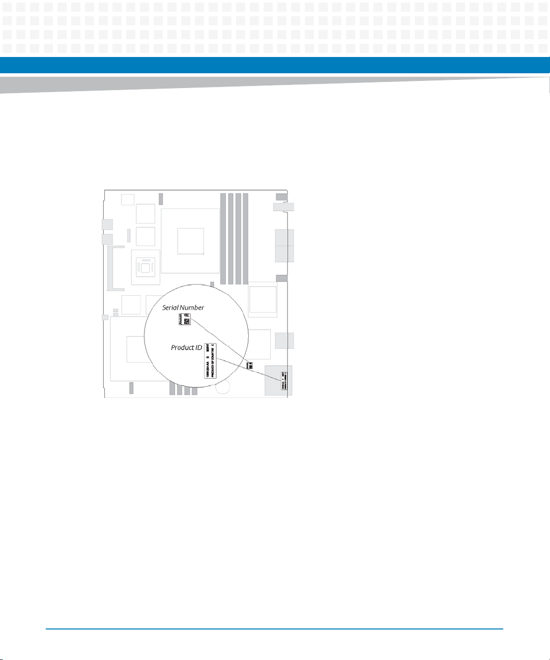
Setup
Whether your board has been customized for options such as a higher processor speed or
additional memory
License agreements (if applicable)
Figure 2-14 Serial Number and Product ID on Top Side
2.4.2 Product Repair
If you plan to return the board to Artesyn Embedded Technologies for service, visit
www.artesyn.com to obtain a Return Merchandise Authorization (RMA) number. We will ask
you to list which items you are returning and the board serial number, plus your purchase order
number and billing information if your ATCA-9305 hardware is out of warranty. Contact our
Test and Repair Services Department for any warranty questions. If you return the board, be
sure to enclose it in an antistatic bag, such as the one in which it was originally shipped.
Please put the RMA number on the outside of the package so we can handle your problem
efficiently. Our service department cannot accept material received without an RMA number.
68
ATCA-9305 User’s Manual (10009109-07)
Page 69
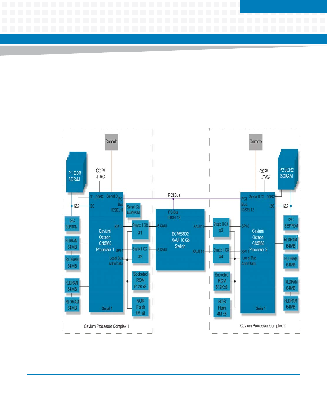
Cavium Processor Complex
3.1 Cavium CN5860 Processor
The ATCA-9305 provides two Cavium processor complexes. The major devices on each
complex consist of the Cavium CN5860 processor, two StratixGX bridges, SDRAM, RLDRAM®,
an I2C EEPROM, socketed ROM, Flash, and the PCI bus interface.
Figure 3-1 Cavium Processor Complex Block Diagram
Chapter 3
ATCA-9305 User’s Manual (10009109-07)
69
Page 70
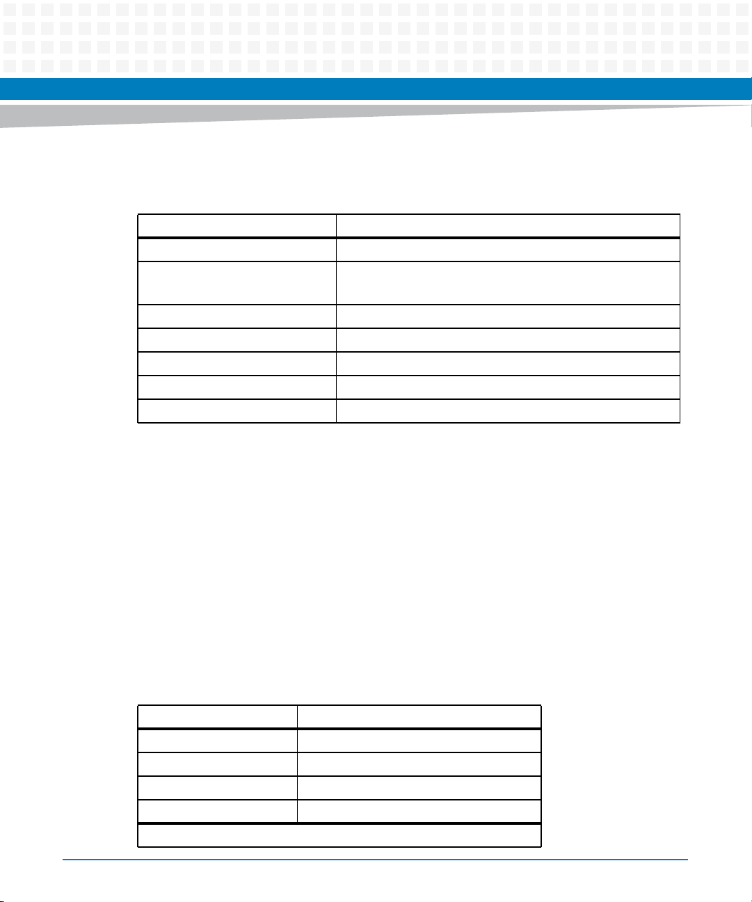
Cavium Processor Complex
The main features of the CN5860 include:
Table 3-1 CN5860 Features
Feature Description
Processor Core Up to 16 cnMIPS™ cores
Core Speed
Network Services Processor (NSP)
System Packet Interface Two SPI-4.2 ports
L2 Cache 2 MB, eight-way set associative
DRAM 144-bit DDR2 DRAM interface
RLDRAM 18-bit RLDRAM, low-latency memory direct access
PCI 64-bit, PCI 2.3 compatible
The CN5860 and switch route packets using SPI-4.2 and control information flow using PCI.
The CN5860 has two SPI-4.2 interfaces with each one supporting up to 16 ports. Two highspeed SPI-4.2 Altera (Stratix™ GX) FPGAs function as the SPI-to-XAUI bridge for each processor
to switch complex. The PCI interface supports up to four ports, consequently a total of 36 ports
can be supported internally by each CN5860.
3.1.1 Cavium Memory Map
Although the Cavium processors are 64-bit, the ATCA-9305 uses a 49-bit implementation.
Refer to the Cavium Networks OCTEON Plus CN58xx Hardware Reference Manual for more
detailed information on the memory map.
up to 800 MHz, processing up to 30 million packets per second
70
Table 3-2 Cavium Address Summary
Hex Physical Address Register Description
1,2000,0000,0000 reserved
1,1F00,0000,0000 Cavium Hardware registers
1,1E00,0000,0000 PCI Memory Space (6)
1,1D00,0000,0000 PCI Memory Space (5)
This depends on how much memory is installed.
ATCA-9305 User’s Manual (10009109-07)
Page 71
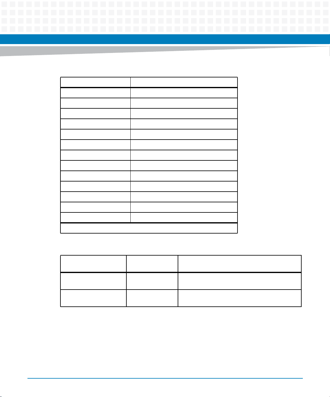
Cavium Processor Complex
Table 3-2 Cavium Address Summary (continued)
Hex Physical Address Register Description
1,1C00,0000,0000 PCI Memory Space (4)
1,1B00,0000,0000 PCI Memory Space (3)
1,1A00,0000,0000 PCI I/O Space
1,1910,0000,0000 reserved
1,1900,0000,0000 PCI Special Space
1,0700,0000,0000 CN58xx Registers
1,0001,0000,0000 reserved
1,0000,0000,0000 Local Boot Bus
0,0004,1000,0000 DDR2 SDRAM, middle block (256-512 MB)
0,0004,0000,0000 reserved
0,0000,2000,0000 DDR2 SDRAM, upper block (512 MB-2 GB)
0,0000,1000,0000 reserved
1
0,0000,0000,0000 DDR2 SDRAM, bottom block (256 MB)
This depends on how much memory is installed.
Table 3-3 Memory Map
Address Range on
Management Processor
0x88000000 .. 0x88ffffff 0x20000000 Local memory of Octeon 1 accessible via PCI from
0x98000000 .. 0x98ffffff 0x20000000 Local memory of Octeon 3 accessible via PCI from
ATCA-9305 User’s Manual (10009109-07)
Address on Octeon
Processor Description
management processor.
management processor.
71
Page 72

Cavium Processor Complex
3.2 PCI
The Cavium is a slave device on the PCI bus. The Cavium U-boot monitor image is provided by
the MPC8548 management processor via PCI. The MPC8548 monitors the Cavium boot status
and has the ability to try alternate boot images if the current one fails.
The CN5860 processor is designed such that another PCI device can initialize its memory
interface, copy code over PCI into its local memory space, and then write a boot release
register.
3.2.1 CN5860 Boot Over PCI
The PCI bus is configured to run at 66 MHz in 64-bit conventional PCI mode. On power-up, the
CN5860 processor’s 16 internal cores are held in reset. The MPC8548 management processor
performs the following steps:
1. Initialize the CN5860 RAM.
2. Copy the CN5860 U-boot to the CN5860 RAM.
3. Copy boot code to the reset vector to jump to the U-boot code in RAM.
4. Release the CN5860 processor cores from reset.
5. Receive return codes from the CN5860 that indicate any boot or POST errors and take the
appropriate action.
The management processor (MPC8548) monitor implements a utility to load non-volatile
memory redundant U-boot images for the CN5860 processors. The utility tags each copy as
primary or secondary.
The U-boot command "oct_moninit" can be used to program a binary boot image for the
Octeon processors into the boot flash device of the management CPU. The management
processor will use this image to start up the Octeon processors.
Syntax:
oct_moninit [.<image-number>] <octeon-processor> <image-address>
72
ATCA-9305 User’s Manual (10009109-07)
Page 73

Parameters
image-number (1 or 2)
Specifies whether to program the primary or backup image. If omitted, both images will be
updated.
octeon-processor (1 or 2)
Specifies which Octeon processor's image is to be updated.
image-address
Address of the binary image after loading it in memory. (e.g. via TFTP)
3.2.2 Cavium Reset
Each CN5860 can be reset independently of the other processor without affecting its
operation. This task is performed by the MPC8548 management processor.
Cavium Processor Complex
ATCA-9305 User’s Manual (10009109-07)
73
Page 74
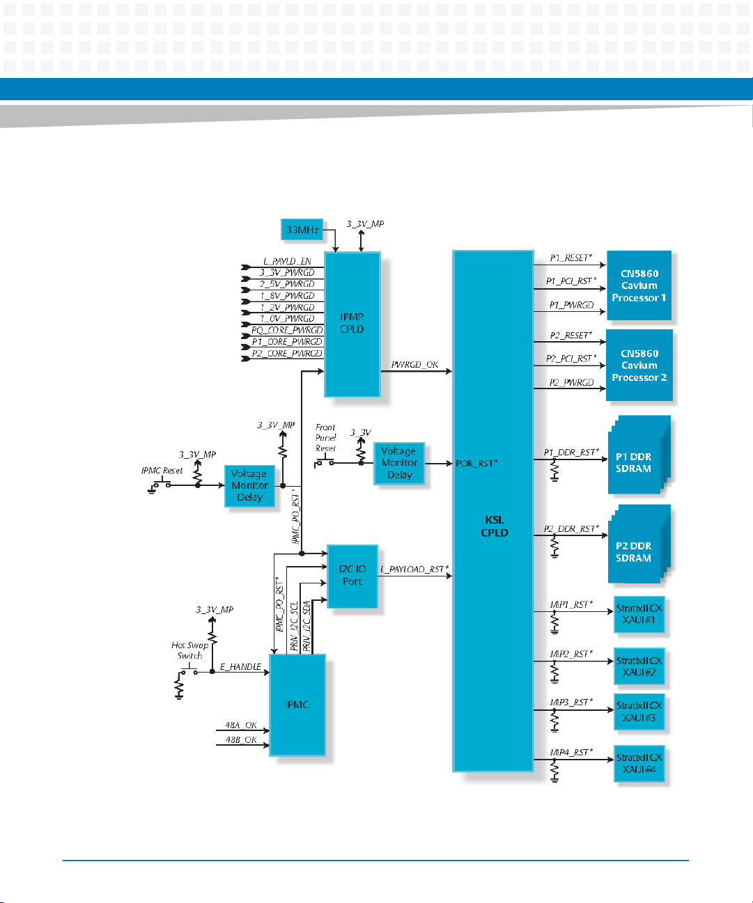
Cavium Processor Complex
Figure 3-2 CN5860 Reset Diagram
74
ATCA-9305 User’s Manual (10009109-07)
Page 75
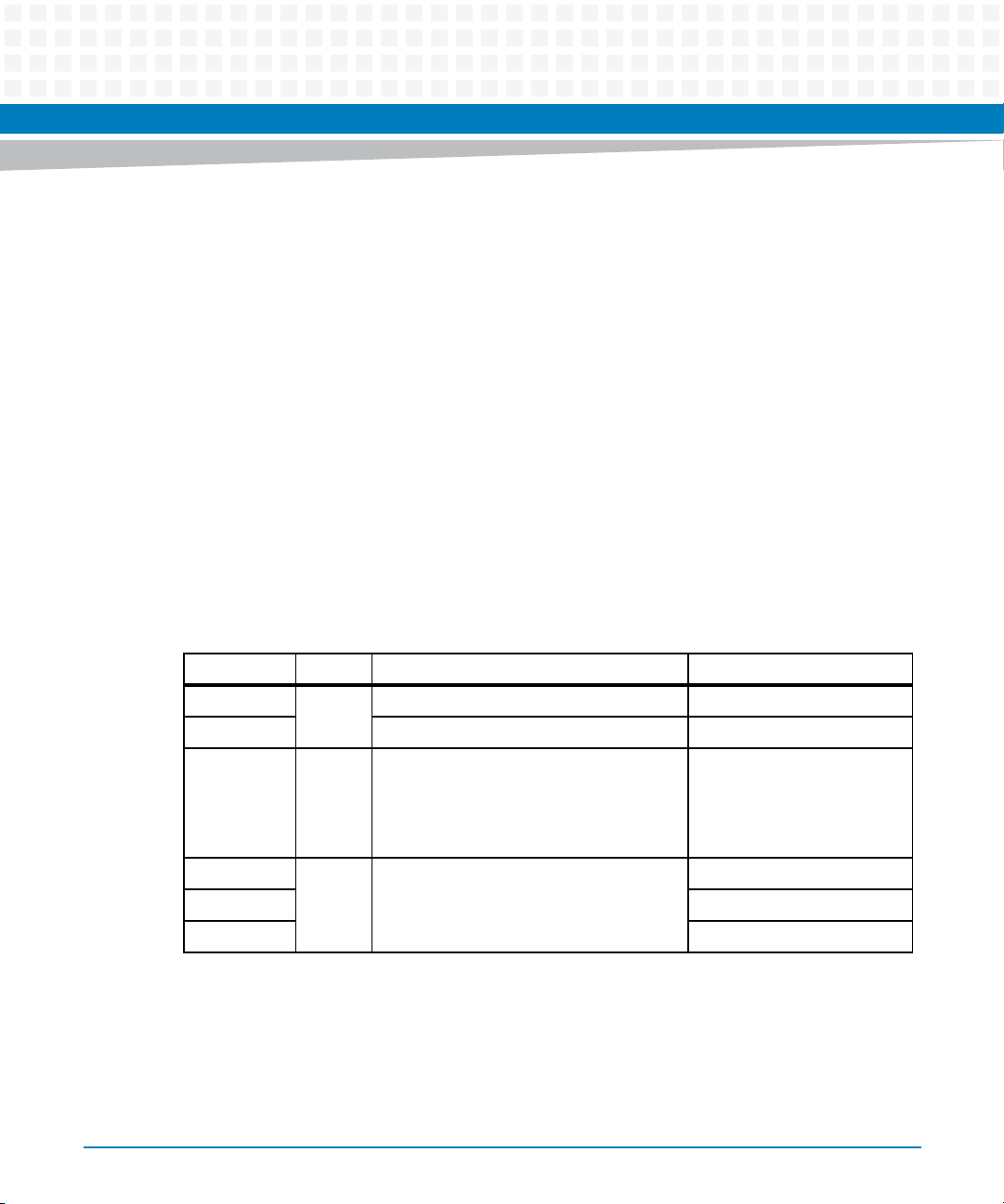
3.3 Cavium Ethernet
The Ethernet address for your board is a unique identifier on a network. The address consists of
48 bits (MAC [47:0]) divided into two equal parts. The upper 24 bits define a unique identifier
that has been assigned to Artesyn Embedded Technologies - Embedded Computing by IEEE.
The lower 24 bits are defined by Artesyn for identification of each of our products.
The Ethernet address for the ATCA-9305 is a binary number referenced as 12 hexadecimal
digits separated into pairs, with each pair representing eight bits. The address assigned to the
ATCA-9305 has the following form:
00 80 F9 xx yy zz
00 80 F9 is Artesyn’s identifier. The last three bytes of the Ethernet address consist of the port
(one byte); 0x99(SPI 1), 0x9A (SPI 2), 0x9B (SPI 3), or 0x9C (SPI 4), followed by the serial
number (two byte hexadecimal). The ATCA-9305 Cavium has been assigned the Ethernet
address range 00:80:F9:99:00:00 to 00:80:F9:9C:FF:FF. The format is shown in Table 3-4.
Cavium Processor Complex
Table 3-4 Ethernet Port Address
Offset MAC Description Ethernet Identifier (hex)
Byte 5 15:0 LSB of (serial number in hex) -
Byte 4 MSB of (serial number in hex) -
Byte 3 23:16 SPI 1
Byte 2 47:24 Assigned to Artesyn by IEEE 0xF9
Byte 1 0x80
Byte 0 0x00
ATCA-9305 User’s Manual (10009109-07)
SPI 2
SPI 3
SPI 4
0x99
0x9A
0x9B
0x9C
75
Page 76

Cavium Processor Complex
The last two bytes, MAC[15:0], are calculated from the serial number stored in the Cavium
EEPROM. This corresponds to the following formula: n –1000, where n is the unique serial
number assigned to each board. So if an ATCA-9305 serial number is 1032, the calculated value
is 32 (2016), and the default Ethernet port addresses are:
Cavium 1 SPI 1 MAC address is: 0x00 0x80 0xF9 0x99 0x00 0x20
Cavium 1 SPI 2 MAC address is: 0x00 0x80 0xF9 0x9A 0x00 0x20
Cavium 2 SPI 1 MAC address is: 0x00 0x80 0xF9 0x9B 0x00 0x20
Cavium 2 SPI 2 MAC address is: 0x00 0x80 0xF9 0x9C 0x00 0x20
3.4 Cavium Monitor
The primary function of the monitor software is to transfer control of the hardware to the
user’s application. Secondary responsibilities include:
low-level initialization of the hardware
diagnostic tests
low-level monitor commands/functions to aid in debug
3.4.1 Start-up Display
At power-up or after a reset, the Cavium monitor runs diagnostics and reports the results in the
start-up display, see an example in Figure 3-3. During the power-up sequence, the monitor
configures the board according to the environment variables (see MPC8548 Environment
Variables on page 260). If the configuration indicates that autoboot is enabled, the monitor
76
ATCA-9305 User’s Manual (10009109-07)
Page 77
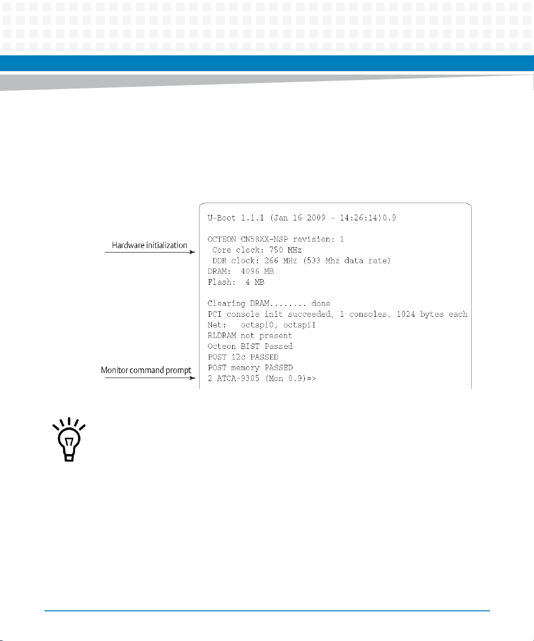
Cavium Processor Complex
attempts to load the application from the specified device. If the monitor is not configured for
autoboot or a failure occurs during power-up, the monitor enters normal command-line mode.
The monitor command prompt in Figure 3-3 is the result of a successful hardware boot of the
ATCA-9305.
Figure 3-3 Example Cavium CN5860 Monitor Start-up Display
There will be either a 1 or 2 in front of the monitor prompt indicating which Cavium processor
is prompting.
3.4.2 Power-up/Reset Sequence
The Cavium CN5860 processor follows the boot sequence in Figure 3-4 before auto-booting
the operating system or application software. At power-up or board reset, the monitor
performs hardware initialization, diagnostic routines, autoboot procedures, and if necessary,
invokes the command line. See Table 3-6 for default Cavium environment variables settings.
ATCA-9305 User’s Manual (10009109-07)
77
Page 78
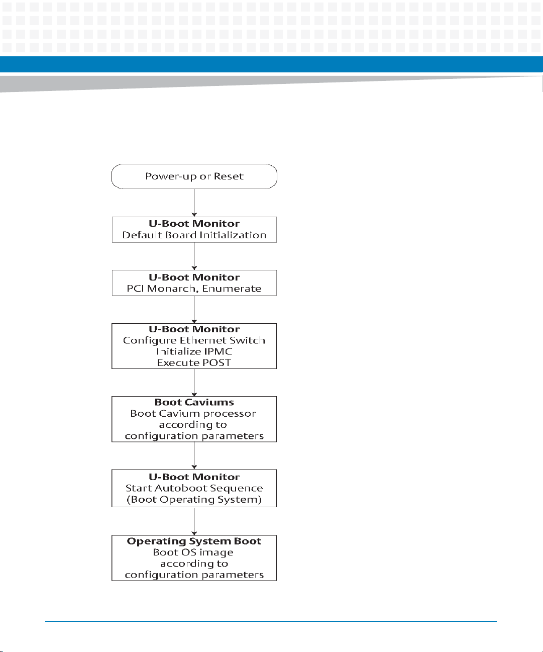
Cavium Processor Complex
Figure 3-4 Power-up/Reset CN5860 Boot Sequence Flowchart
78
ATCA-9305 User’s Manual (10009109-07)
Page 79
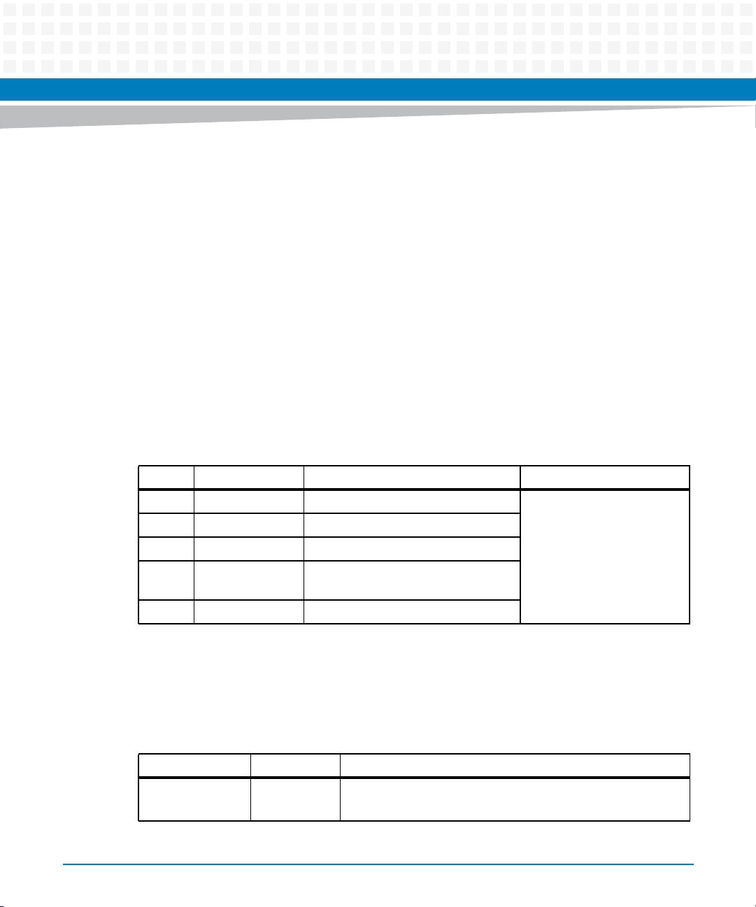
Cavium Processor Complex
3.4.3 Diagnostic Tests During Power-up and Reset
The Cavium monitor diagnostic tests can be executed during power-up or invoked from the
monitor’s command prompt. This is accomplished by changing the state of the monitor
configuration parameters that define power-up and reset diagnostics mode. If the
powerondiags parameter is set to “on”, the monitor invokes the diagnostic tests after a reset
of the hardware. Results are displayed to the console including whether the test passed or
failed.
3.4.3.1 POST Diagnostic Results
The ATCA-9305 Power-On Self-Test (POST) diagnostic results are stored as a 32-bit value in
memory accessible by the management console at location 0x80080A6C (where 0x80080A6C
is a 8548 or an Octeon address). Each bit indicates the result of a specific test, so this field can
store the results of up to 32 diagnostic tests. Table 3-5 assigns the bits to specific tests.
Table 3-5 POST Diagnostic Results–Bit Assignments
Bit Diagnostic Test Description Value
0-1 Reserved
2 DRAM Verify address and data lines are intact
3 Cavium BIST -
2
4I
5-31 Reserved
C Verify all local I2C devices are
connected to the I
3.4.4 Cavium Environment Variables
The following table lists the standard Cavium environment variables:
Table 3-6 Standard Cavium Environment Variables
Variable Default Value Description
baudrate 115200 Console port baud rate
Valid rates: 9600, 14400, 19200, 38400, 57600, 115200
ATCA-9305 User’s Manual (10009109-07)
2
C bus
0 Passed the test
1 Failure detected
79
Page 80

Cavium Processor Complex
Table 3-6 Standard Cavium Environment Variables (continued)
Variable Default Value Description
bootcmd " " Command to execute when auto-booting or executing the
bootdelay 0 Choose the number of seconds the Monitor counts down
bootfile " " Path to boot file on server (used with TFTP)–set this to
ethaddr undefined SPI 1 MAC address
eth1addr undefined SPI 2 MAC address
ethact octspi0 Specifies Ethernet port to use
gatewayip 0.0.0.0 Select the network gateway machine IP address
‘bootd’ command
before booting user application code
Valid options: time in seconds, -1 to disable autoboot
“path/file.bin” to specify filename and location of the file
to load.
hostname none Target hostname
ipaddr 0.0.0.0 Board IP address
loadaddr 0x20000000 Define the address to download user application code (used
with TFTP)
netmask 0.0.0.0 Board sub-network mask
powerondiags off Turns POST diagnostics on or off after power-on/reset
Valid options: on, off
rootpath eng/ Path name of the NFS’ server root file system
serial# xxxxx Board serial number
serverip 0.0.0.0 Boot server IP address
stderr serial Sets the standard destination for console error reporting
Valid options: serial, pci
stdin serial Sets the standard source for console input
Valid options: serial, pci
stdout serial Sets the standard destination for console output
Valid options: serial, pci
80
ATCA-9305 User’s Manual (10009109-07)
Page 81
Table 3-6 Standard Cavium Environment Variables (continued)
Variable Default Value Description
spi_num_ports undefined Defines the number logical ports per SPI interface. Possible
3.5 Memory
The processor complex supports DDR2 Synchronous DRAM (SDRAM) and Reduced Latency
DRAM (RLDRAM) memory devices. SCP variants do not support RLDRAM.
Cavium Processor Complex
values are 1 (default) and 16. If set to 16, additional logical
network interfaces are generated named octspi0.1, octspi0.2,
... octspi0.15 and octspi1.1, octspi1.2, ..., octspi1.15 for logical
ports 1 .. 15 on SPI interface 0 and 1 respectively.
octspi0/octspi1 use port number 0.
The commands eth_eg_map, eth_ig_map and eth_map_show
are available in the 16-port configuration for mapping ports to
ethernet VLANs and vice versa.
3.5.1 DDR2 SDRAM
The ATCA-9305 supports up to 16 gigabytes of 144-bit wide DDR2 SDRAM per processor
complex. The SDRAM interface clock speed frequency is up to 400 MHz. The four low-profile,
dual-inline memory modules (buffered DIMM) are installed in 240-pin very low profile (VLP)
sockets to reduce board density and routing constraints. A 2 KB EEPROM on the DIMM provides
the serial presence detection (SPD). On-card SDRAM occupies physical addresses from
0,0000,0000,000016 to 0,0003,FFFF,FFFF16.
Each processor memory bus is operating in 144-bit mode. Error-correcting Code (ECC) is
performed on the memory bus so that the CN5860 detects all double-bit errors, multi-bit
errors within a nibble, and corrects all single-bit errors.
ATCA-9305 User’s Manual (10009109-07)
81
Page 82
Cavium Processor Complex
3.5.2 RLDRAM
Each CN5860 supports 256 MB Common I/O (CIO) RLDRAM operating up to 400 MHz
(depends on the processor speed). The Micron RLDRAM II is organized as 32Mx18x8 internal
banks. The DDR I/O interface transfers two data words per clock cycle. Output data is
referenced to the free-running output data clock. Read and write accesses to the RLDRAM are
burst-oriented. RLDRAM is accessed by using Cavium-specific instructions which operate on
MIPS Coprocessor 2. SCP variants of the ATCA-9305 do not support RLDRAM.
3.5.3 I2C EEPROM
Each Cavium processor complex has one user EEPROM device for parameter storage located on
the I2C bus, address 0xA8. The I2C bus for each processor is completely independent from the
other CN5860 processor and MPC8548 processor I2C buses. The Atmel two-wire serial
EEPROM on each CN5860 processor I2C interface consists of the Serial Clock (SCL) input and
the Serial Data (SDA) bidirectional lines.
Table 3-7 Cavium NVRAM Memory Map
Address Offset (hex) Description Window Size (bytes)
0x1E00-0x1FFF Monitor parameters 256
0x0000-0x1D36 User defined 79F
3.5.4 Flash, 512 KB x 8
The 512 KB of 32-pin PLCC socketed flash starts at physical address1D46,000016 and is used
for Engineering code. The StrataFlash features high-performance fast asynchronous access
times, low power, and flexible security options.
3.5.5 Flash, 4 MB x 16
The 4 MB soldered NOR flash starts at physical address 1D05,000016. The 32-Mbit device
provides CN5860 code storage and non-volatile memory.
82
ATCA-9305 User’s Manual (10009109-07)
Page 83
3.6 StratixGX Interconnect
The Altera StratixGX FPGA provides the high-speed SPI-4.2 interconnect. Each complex has
dual SPI-to-XAUI bridges connected to the XAUI Ethernet switch ports.
3.6.1 PLD Registers
The FPGA bridge is located at address 0x1D030000. Use the following registers to access the
XAUI to SPI bridge configuration registers.
PLD registers information can be requested via sales/marketing office.
Cavium Processor Complex
3.6.1.1 Data Registers
Table 3-8 Data 31:24 (0x0)
Bits R/W Function
7 R/W Data 31
6 R/W Data 30
5 R/W Data 29
4 R/W Data 28
3 R/W Data 27
2 R/W Data 26
1 R/W Data 25
0 R/W Data 24
ATCA-9305 User’s Manual (10009109-07)
83
Page 84
Cavium Processor Complex
Table 3-9 Data 23:16 (0x1)
Bits R/W Function
7 R/W Data 23
6 R/W Data 22
5 R/W Data 21
4 R/W Data 20
3 R/W Data 19
2 R/W Data 18
1 R/W Data 17
0 R/W Data 16
Table 3-10 Data 15:8 (0x2)
Bits R/W Function
7 R/W Data 15
6 R/W Data 14
5 R/W Data 13
4 R/W Data 12
3 R/W Data 11
2 R/W Data 10
1 R/W Data 9
0 R/W Data 8
Table 3-11 Data 7:0 (0x3)
Bits R/W Function
7 R/W Data 7
6 R/W Data 6
5 R/W Data 5
4 R/W Data 4
3 R/W Data 3
84
ATCA-9305 User’s Manual (10009109-07)
Page 85
Table 3-11 Data 7:0 (0x3) (continued)
Bits R/W Function
2 R/W Data 2
1 R/W Data 1
0 R/W Data 0
3.6.1.2 Address Registers
Table 3-12 Address 9:8 (0x4)
Bits R/W Function
7- Reserved
Cavium Processor Complex
6-
5-
4-
3-
2-
1 R/W Address 9
0 R/W Address 8
Table 3-13 Address 7:0 (0x5)
Bits R/W Function
7 R/W Address 7
6 R/W Address 6
5 R/W Address 5
4 R/W Address 4
3 R/W Address 3
2 R/W Address 2
1 R/W Address 1
ATCA-9305 User’s Manual (10009109-07)
85
Page 86
Cavium Processor Complex
Table 3-13 Address 7:0 (0x5) (continued)
Bits R/W Function
0 R/W Address 0
3.6.1.3 Control Register
The write only Control register performs two functions:
Writing a value of 0x01 causes the contents of the Data registers to be written to the FPGA
bridge at the location specified by the Address registers.
Writing a value of 0x02 causes the contents of the Data registers to be overwritten by the
contents of the FPGA bridge at the location specified by the Address registers.
Writing any other value to the Control register will be ignored.
86
Table 3-14 Control (0x6)
Bits R/W Function
7- Reserved
6-
5-
4-
3-
2-
1W Read
0 W Write
ATCA-9305 User’s Manual (10009109-07)
Page 87
3.6.1.4 Version Register
This read-only register tracks the PLD versions. The version is hard coded in the PLD and
changes with every released code change. Version starts at 0116.
Table 3-15 Version (0x7)
Bits R/W Function
7 R 0x01
6R
5R
4R
3R
2R
1R
Cavium Processor Complex
0R
3.6.1.5 Scratch Register
All registers in this range act as the same register.
Table 3-16 Scratch (0x8-0x3F)
Bits R/W Function
7 R/W
6 R/W
5 R/W
4 R/W
3 R/W
2 R/W
1 R/W
0 R/W
ATCA-9305 User’s Manual (10009109-07)
87
Page 88

Cavium Processor Complex
Read Example:
To read the FPGA bridge SPI_COMMAND register at 0x204, use the following commands.
Set address bits 9:8.
=>write64b 1d030004 02
Set address bits 7:0.
=>write64b 1d030005 04
Perform a read.
=>write64b 1d030006 02
Display the results.
=>read64l 1d030000
Write Example:
To write to the FPGA bridge MAC_CMD_CFG register at 0x00C, use the following commands.
Set data bits 31:24.
=>write64b 1d030000 a9
Set data bits 23:16.
=>write64b 1d030001 b8
Set data bits 15:8.
=>write64b 1d030002 c7
Set data bits 7:0.
=>write64b 1d030003 d6
Set address bits 9:8.
=>write64b 1d030004 00
Set address bits 7:0.
88
ATCA-9305 User’s Manual (10009109-07)
Page 89

=>write64b 1d030005 0c
Perform a write.
=>write64b 1d030006 01
3.7 Headers and Connectors
3.7.1 COP/JTAG Headers
The CN5860 processor complex uses headers J1 and J15 for debug.
Table 3-17 CN5860 Processor COP/JTAG Headers
Cavium Processor Complex
Pin J1 (processor 2) J15 (processor 1)
1 P2_ETRST* P1_ETRST*
2 ground ground
3 P2_TDI P1_TDI
4 ground ground
5 P2_ETDO P1_ETDO
6 ground ground
7 P2_TMS P1_TMS
8 ground ground
9 P2_TCK P1_TCK
10 ground ground
11 P2_EJTAG_RST P1_EJTAG_RST
12 key (pin not installed) key (pin not installed)
13 P2_EJTAG_DINT P1_EJTAG_DINT
14 P2_COP_PWR (3.3V) P1_COP_PWR (3.3V)
ATCA-9305 User’s Manual (10009109-07)
89
Page 90
Cavium Processor Complex
3.7.2 Console Serial Ports
Connectors P6 (processor P1) and P5 (processor P2) access the CN5860 processors for
Engineering debug use only. The suppor ted baud rates for these ports operate at 9600, 14400,
19200, 38400, 57600, and 115200 bps. (The default rate is 115200 bps.)
Table 3-18 CN5860 Processor Debug Headers
Pin P6 P5
1 no connect no connect
2 P1_SER1_RXD P2_SER1_RXD
3 P1_SER1_TXD P2_SER1_TXD
4 no connect no connect
5 signal ground signal ground
6-7 shield signal ground
90
ATCA-9305 User’s Manual (10009109-07)
Page 91

Management Complex
4.1 MPC8548 Processor
The ATCA-9305 management complex is comprised of the Freescale MPC8548 processor,
CPLD, SDRAM, flash, I2C EEPROM, Real-time Clock, and PCI bus interface. Board power-up,
booting and monitoring the Cavium processors, PCI bus arbitration, interrupt servicing,
memory persistence functionality, and other board level management tasks are implemented
using the MPC8548 processor. The MPC8548 stores the Cavium operating system and monitor
code in its local memory and then uses the boot over PCI functionality to bring up the Cavium
processor complexes. The CPLD registers are described in Chapter 5, Management Processor
CPLD. See Chapter 9, Management Processor Monitor for the Management Processor Monitor.
The management complex connects to the Broadcom Ethernet switch via a 1000BASE-T
Ethernet port. This connection uses the TSEC2 interface operating in SGMII mode. See Chapter
6, Ethernet Interface, on page 129.
Chapter 4
ATCA-9305 User’s Manual (10009109-07)
91
Page 92
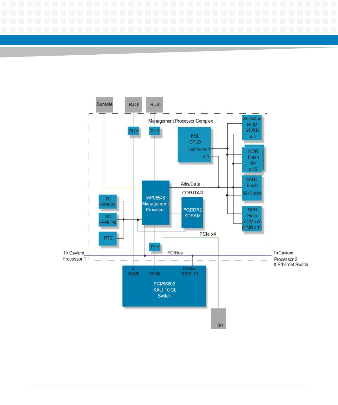
Management Complex
Figure 4-1 MPC8548 Management Processor Complex Block Diagram
92
ATCA-9305 User’s Manual (10009109-07)
Page 93
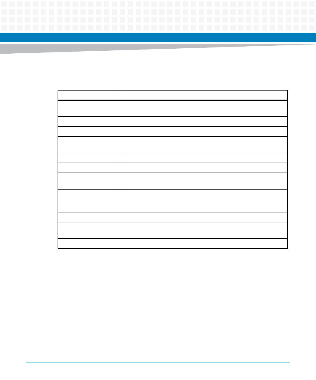
Management Complex
The MPC8548 processor has the following features:
Table 4-1 MPC8548 Features
Feature Description
L1 Cache 32-kilobyte data and instruction caches with parity protection, 32-byte
line, eight-way set associative
L2 Cache 512 kilobytes, eight-way set associative
CPU Core Speed 1 GHz with a 400 MHz DDR2 bus
DDR2 Memory Controller 64-bit data interface, four banks of memory supported (each up to 4 GB),
full ECC support
2
Dual I2C Controllers Two-wire interface, master or slave I
Boot Sequencer Loads configuration data from serial ROM at reset via the I
Ethernet Four 10/100/1000 enhanced three-speed controllers (eTSECs), full-/half-
duplex support, MAC address recognition
C support
2
C interface
Local Bus Controller (LBC) DDR2 SDRAM memory controller, General Purpose Chip Select Machine
(GPCM), three User-Programmable Machines (UPM), eight chip selects
support eight external slaves
PCI 64-bit, PCI 2.2 compatible
PCI Express Single x4 PCIe high-speed interconnect, complies with PCI Express™ Base
Specification Revision 1.0a
JTAG Complies with IEEE Std. 1149.1
For more detailed information, reference the Freescale MPC8548E PowerQUICC™ III Integrated
Processor Family Reference Manual.
4.1.1 MPC8548 Memory Map
The monitor can boot from either the soldered flash (Bank 1, default) or the socketed PLCC
device. Based on the configuration header (see Configuration Header on page 61) either the
socketed device or soldered flash is mapped to the boot bank at FFF8, 000016, see Figure 4-2.
Information on particular portions of the memory map can be found in later sections of this
manual, see Table 4-2.
ATCA-9305 User’s Manual (10009109-07)
93
Page 94
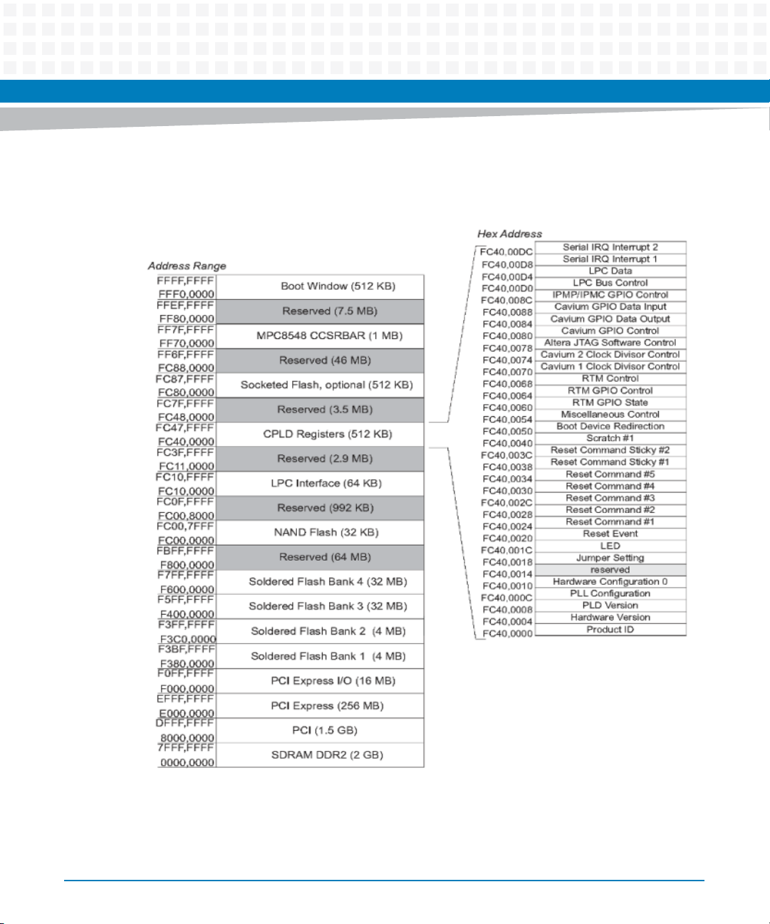
Management Complex
Figure 4-2 MPC8548 Memory Map
94
ATCA-9305 User’s Manual (10009109-07)
Page 95

Management Complex
Table 4-2 MPC8548 Address Summary
Hex Physical Address Access Mode Register Description See Page
FFF8,0000 R/W Boot window (512 KB) –
FF80.0000 - reserved (7.5 MB)
FF70,0000 R/W MPC8548 CCSRBAR (1MB) –
FC88,0000 – reserved (46 MB)
FC80,0000 R/W Socketed flash, optional (512 KB) 99
FC48,0000 – reserved (3.5 MB)
FC40,00DC0 R/W Serial IRQ Interrupt 2 127
FC40,00D8 R/W Serial IRQ Interrupt 1 126
FC40,00D4 R/W LPC Data 126
FC40,00D0 R/W Low Pin Count (LPC) Bus Control 125
FC40,008C R/W IPMP/IPMC GPIO Control 125
FC40,0088 R/W Cavium GPIO Data Input 124
FC40,0084 R/W Cavium GPIO Data Output 123
FC40,0080 R/W Cavium GPIO Control 123
FC40,0078 R/W Altera JTAG Chain Software Control 122
FC40,0074 R/W Cavium 2 C_MUL Clock Divisor
FC40,0070 R/W Cavium 1 C_MUL Clock Divisor
FC40,0068 R/W RTM Control 120
FC40,0064 R/W RTM GPIO Control 119
FC40,0060 R/W RTM GPIO State 119
FC40,0054 R/W Miscellaneous Control (SIO, I2C,
FC40,0050 R/W Boot Device Redirection 116
FC40,0040 R/W Scratch #1 -
FC40,003C R/W Reset Command Sticky #2 116
FC40,0038 R/W Reset Command Sticky #1 115
ATCA-9305 User’s Manual (10009109-07)
121
Control
120
Control
117
Test Clock)
95
Page 96

Management Complex
Table 4-2 MPC8548 Address Summary (continued)
Hex Physical Address Access Mode Register Description See Page
FC40,0034 W Reset Command #5 114
FC40,0030 W Reset Command #4 114
FC40,002C W Reset Command #3 113
FC40,0028 W Reset Command #2 112
FC40,0024 W Reset Command #1 112
FC40,0020 R/W Reset Event 111
FC40,001C R/W LED 110
FC40,0018 R/W Jumper Setting 109
FC40,0014 - reserved -
FC40,0010 R/W Hardware Configuration 0 109
FC40,000C R/W PLL Configuration 108
96
FC40,0008 R/W PLD Version 108
FC40,0004 R/W Hardware Version 107
FC40,0000 R/W Product ID (CPLD 512 KB) 106
FC11,0000 reserved (2.9 MB)
FC10,0000 R/W LPC Interface (64 KB) 97
FC00,8000 - reserved (992 KB)
FC00,0000 R/W NAND flash (32 KB) 100
F800,0000 - reserved (64 MB)
F600,0000 R/W Soldered flash bank 4 (32 MB) 99
F400,0000 R/W Soldered flash bank 3 (32 MB) 99
F080,0000 - reserved (56 MB)
F3C0,0000 R/W Soldered flash bank 2 (4 MB) 99
F380,0000 R/W Soldered flash bank 1 (4 MB) 99
F000,0000 R/W PCI Express I/O space (16 MB) 101
E000,0000 R/W PCI Express (256 MB) 101
8000,0000 R/W PCI (1.5 GB) 100
ATCA-9305 User’s Manual (10009109-07)
Page 97
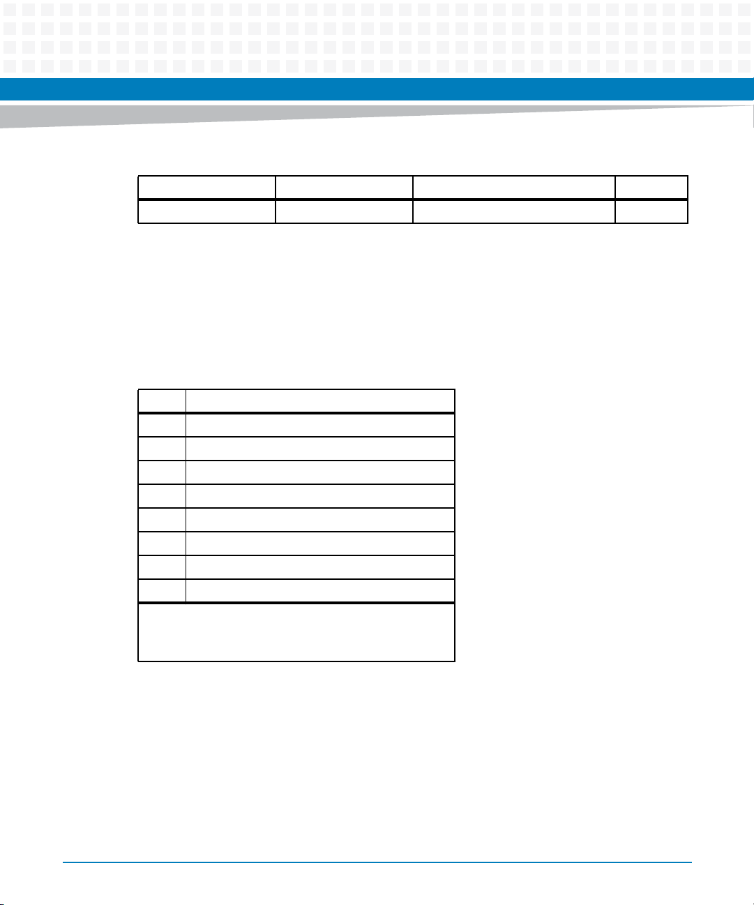
Table 4-2 MPC8548 Address Summary (continued)
Hex Physical Address Access Mode Register Description See Page
0000,0000 R/W SDRAM DDR2 (2 GB) 99
4.1.2 Chip Selects
The MPC8548 memory controller functions as a chip select (CS) generator to access on-board
memory devices. In order to select one device over another, the following chip selects have
been established.
Table 4-3 Device Chip Selects
Pin Signal
0 Boot bank
1 Soldered flash boot bank 1 (default)
Management Complex
1
2 Soldered flash boot bank 2
3 Socketed flash (optional)
4 KSL CPLD registers
5 NAND flash
6 Soldered NOR flash boot banks 3 and 4
7 LPC interface
Boot bank can be either socketed flash, flash 1, or flash 2;
depending on the jumper setting (see Figure 2-11).
ATCA-9305 User’s Manual (10009109-07)
97
Page 98
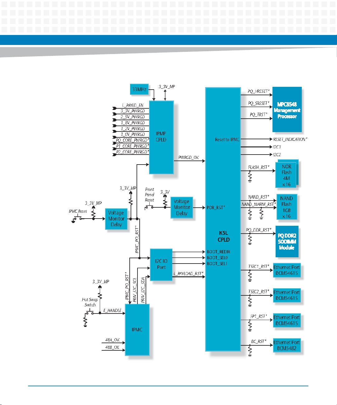
Management Complex
Figure 4-3 MPC8548 Reset Diagram
98
ATCA-9305 User’s Manual (10009109-07)
Page 99

4.2 Memory
The memory devices in the management complex consist of:
1 GB DDR2 SDRAM
512 KB socketed flash
8 MB soldered NOR flash (two redundant banks of 4 MB each)
1 GB soldered NAND flash (optional)
512 Mb or 64 MB soldered NOR flash
4.2.1 SDRAM
This is a specialized, socketed, 200-pin, small outline, clocked, dual in- line, memory module
(SO-CDIMM). It provides Error-correcting Code (ECC) on the SDRAM memory bus operating at
200 MHz. The MPC8548 detects all double-bit errors, multi-bit errors within a nibble and
corrects all single-bit errors.
Management Complex
The 128M X 72 DDR2 SDRAM is a high-density, un-buffered SO-CDIMM. This module consists
of nine 128x8-bit with eight banks DDR2 SDRAMs, a zero delay phase-lock loop (PLL) clock, and
a 2 KB serial presence detect (SPD) EEPROM. The SDRAM starts at physical address
0000,0000
16.
4.2.2 Flash
There are several flash devices on the local bus interfacing the CPLD and MPC8548 processor.
The four soldered flash banks are labeled 1 through 4:
Banks 1 and 2 are the MPC8548 U-boot banks (see “4M”). These boot banks are used in the
boot redirection scheme, see “BOOT DEVICE REDIRECTION (BDR).”
Banks 3 and 4 are physically one device, but appear in the software as two banks of 32 MB
(see “64 MB”). These are for general purpose storage.
4.2.2.1 512 KB
The 512 KB of 32-pin PLCC socketed flash starts at physical address FC80,000016 and is used for
Engineering code. The StrataFlash (P33) features high-performance fast asynchronous access
times, low power, and flexible security options.
ATCA-9305 User’s Manual (10009109-07)
99
Page 100

Management Complex
4.2.2.2 4M
The two 4 MB soldered flash devices are used for MPC8548 boot code. This redundant bank
configuration allows booting from either bank in case of corruption in one bank. See BOOT
DEVICE REDIRECTION (BDR) on page 194. The SST NOR flash devices are organized as 4Mx8 in a
dual-bank architecture for concurrent read/write operation with hardware and software data
protection schemes. These devices start at physical addresses F380,000016 (boot bank 1) and
F3C0,000016 (boot bank 2).
4.2.2.3 1 GB(optional)
The ATCA-9305 uses 1 GB of M-Systems DiskOnChip (mDOC H3) NAND flash starting at
physical address FC00,000016 for non-volatile RAM storage and True Flash File System (TFFS).
This memory incorporates an embedded flash controller and memory, and includes hardware
protection and security-enabling features, an enhanced programmable boot block enabling
eXecution In Place (XIP) functionality using 16-bit access, user-controlled One Time
Programmable (OTP) partitions, and 6-bit Error Detection Code/Error Correction Code
(EDC/ECC).
4.2.2.4 64 MB
The 64 MB soldered NOR flash starts at physical address F400,000016 (bank 3). The 64-Mbit
P33 device provides CN5860 code storage and non-volatile memory.
4.3 PCI
The MPC8548 performs all the functions of a PCI host and monarch, and handles all arbitration
and enumeration functions. PCI starts at physical address 8000,000016.
The PCI bus connects to both Cavium processors, the MPC8548 processor and the Broadcom
Ethernet switch, see Table 4-4. All of the devices on the PCI bus can operate at 66 MHz and
perform 64-bit transactions in conventional PCI mode except for the Broadcom switch. The
switch has a 32-bit PCI bus.
100
ATCA-9305 User’s Manual (10009109-07)
 Loading...