

Page 1

ATCA-7350
Installation and Use
P/N: 6806800G59G
September 2014
Page 2

©
Copyright 2014 Artesyn Embedded Technologies, Inc.
All rights reserved.
Trademarks
Artesyn Embedded Technologies, Artesyn and the Artesyn Embedded Technologies logo are trademarks and service marks of
Artesyn Embedded Technologies, Inc.© 2014 Artesyn Embedded Technologies, Inc. All other product or service names are the
property of their respective owners.
Intel® is a trademark or registered trademark of Intel Corporation or its subsidiaries in the United States and other countries.
Java™ and all other Java-based marks are trademarks or registered trademarks of Oracle America, Inc. in the U.S. and other countries.
Microsoft®, Windows® and Windows Me® are registered trademarks of Microsoft Corporation; and Windows XP™ is a trademark of
Microsoft Corporation.
PICMG®, CompactPCI®, AdvancedTCA™ and the PICMG, CompactPCI and AdvancedTCA logos are registered trademarks of the PCI
Industrial Computer Manufacturers Group.
UNIX® is a registered trademark of The Open Group in the United States and other countries.
Notice
While reasonable efforts have been made to assure the accuracy of this document, Artesyn assumes no liability resulting from any
omissions in this document, or from the use of the information obtained therein. Artesyn reserves the right to revise this document
and to make changes from time to time in the content hereof without obligation of Artesyn to notify any person of such revision or
changes.
Electronic versions of this material may be read online, downloaded for personal use, or referenced in another document as a URL to
an Artesyn website. The text itself may not be published commercially in print or electronic form, edited, translated, or otherwise
altered without the permission of Artesyn.
It is possible that this publication may contain reference to or information about Artesyn products (machines and programs),
programming, or services that are not available in your country. Such references or information must not be construed to mean that
Artesyn intends to announce such Artesyn products, programming, or services in your country.
Limited and Restricted Rights Legend
If the documentation contained herein is supplied, directly or indirectly, to the U.S. Government, the following notice shall apply
unless otherwise agreed to in writing by Artesyn.
Use, duplication, or disclosure by the Government is subject to restrictions as set forth in subparagraph (b)(3) of the Rights in
Technical Data clause at DFARS 252.227-7013 (Nov. 1995) and of the Rights in Noncommercial Computer Software and
Documentation clause at DFARS 252.227-7014 (Jun. 1995).
Contact Address
Artesyn Embedded Technologies Artesyn Embedded Technologies
Marketing Communications
2900 S. Diablo Way, Suite 190
Tempe, Arizona 85282
Lilienthalstr. 17-19
85579 Neubiberg/Munich
Germany
Page 3

Contents
About this Manual . . . . . . . . . . . . . . . . . . . . . . . . . . . . . . . . . . . . . . . . . . . . . . . . . . . . . . . . . . . . . . . . . . . . . . . 15
1 Introduction . . . . . . . . . . . . . . . . . . . . . . . . . . . . . . . . . . . . . . . . . . . . . . . . . . . . . . . . . . . . . . . . . . . . . . . . . 21
1.1 Features . . . . . . . . . . . . . . . . . . . . . . . . . . . . . . . . . . . . . . . . . . . . . . . . . . . . . . . . . . . . . . . . . . . . . . . . . . . 21
1.2 Standard Compliances . . . . . . . . . . . . . . . . . . . . . . . . . . . . . . . . . . . . . . . . . . . . . . . . . . . . . . . . . . . . . . 24
1.3 Ordering Information . . . . . . . . . . . . . . . . . . . . . . . . . . . . . . . . . . . . . . . . . . . . . . . . . . . . . . . . . . . . . . . 25
1.3.1 Supported Board Models. . . . . . . . . . . . . . . . . . . . . . . . . . . . . . . . . . . . . . . . . . . . . . . . . . . . . . 25
1.3.2 Board Accessories . . . . . . . . . . . . . . . . . . . . . . . . . . . . . . . . . . . . . . . . . . . . . . . . . . . . . . . . . . . . 26
2 Hardware Preparation and Installation . . . . . . . . . . . . . . . . . . . . . . . . . . . . . . . . . . . . . . . . . . . . . . . . . 27
2.1 Overview . . . . . . . . . . . . . . . . . . . . . . . . . . . . . . . . . . . . . . . . . . . . . . . . . . . . . . . . . . . . . . . . . . . . . . . . . . 27
2.2 Unpacking and Inspecting the Blade . . . . . . . . . . . . . . . . . . . . . . . . . . . . . . . . . . . . . . . . . . . . . . . . . . 27
2.3 Environmental and Power Requirements . . . . . . . . . . . . . . . . . . . . . . . . . . . . . . . . . . . . . . . . . . . . . . 30
2.3.1 Environmental Requirements. . . . . . . . . . . . . . . . . . . . . . . . . . . . . . . . . . . . . . . . . . . . . . . . . . 30
2.3.2 Power Requirements . . . . . . . . . . . . . . . . . . . . . . . . . . . . . . . . . . . . . . . . . . . . . . . . . . . . . . . . . 31
2.4 Precautions . . . . . . . . . . . . . . . . . . . . . . . . . . . . . . . . . . . . . . . . . . . . . . . . . . . . . . . . . . . . . . . . . . . . . . . . 32
2.4.1 ESD Prevention . . . . . . . . . . . . . . . . . . . . . . . . . . . . . . . . . . . . . . . . . . . . . . . . . . . . . . . . . . . . . . 33
2.5 Checking the Installation Environment . . . . . . . . . . . . . . . . . . . . . . . . . . . . . . . . . . . . . . . . . . . . . . . . 34
2.5.1 Wearing the ESD-Preventive Wrist Strap . . . . . . . . . . . . . . . . . . . . . . . . . . . . . . . . . . . . . . . . 34
2.5.2 Removing Blank Filler Blades . . . . . . . . . . . . . . . . . . . . . . . . . . . . . . . . . . . . . . . . . . . . . . . . . . 36
2.6 Installing Blade Accessories . . . . . . . . . . . . . . . . . . . . . . . . . . . . . . . . . . . . . . . . . . . . . . . . . . . . . . . . . . 38
2.6.1 Precautions . . . . . . . . . . . . . . . . . . . . . . . . . . . . . . . . . . . . . . . . . . . . . . . . . . . . . . . . . . . . . . . . . 38
2.6.2 Optional Components Supported by the ATCA-7350 . . . . . . . . . . . . . . . . . . . . . . . . . . . . . 39
2.6.3 Preparations. . . . . . . . . . . . . . . . . . . . . . . . . . . . . . . . . . . . . . . . . . . . . . . . . . . . . . . . . . . . . . . . . 40
2.6.4 DIMM. . . . . . . . . . . . . . . . . . . . . . . . . . . . . . . . . . . . . . . . . . . . . . . . . . . . . . . . . . . . . . . . . . . . . . . 41
2.6.4.1 Installing the DIMM . . . . . . . . . . . . . . . . . . . . . . . . . . . . . . . . . . . . . . . . . . . . . . . . . 42
2.6.4.2 Replacing the DIMM . . . . . . . . . . . . . . . . . . . . . . . . . . . . . . . . . . . . . . . . . . . . . . . . . 44
2.6.5 Hard Disk . . . . . . . . . . . . . . . . . . . . . . . . . . . . . . . . . . . . . . . . . . . . . . . . . . . . . . . . . . . . . . . . . . . 46
2.6.5.1 Installing the Hard Disk . . . . . . . . . . . . . . . . . . . . . . . . . . . . . . . . . . . . . . . . . . . . . . 46
2.6.5.2 Replacing the Hard Disk . . . . . . . . . . . . . . . . . . . . . . . . . . . . . . . . . . . . . . . . . . . . . 49
2.7 Installing and Removing the Blade . . . . . . . . . . . . . . . . . . . . . . . . . . . . . . . . . . . . . . . . . . . . . . . . . . . . 51
2.7.1 Installation . . . . . . . . . . . . . . . . . . . . . . . . . . . . . . . . . . . . . . . . . . . . . . . . . . . . . . . . . . . . . . . . . . 51
2.7.1.1 Installing the ATCA-7350 in a Powered Shelf . . . . . . . . . . . . . . . . . . . . . . . . . . . 51
2.7.1.2 Checking the Installation . . . . . . . . . . . . . . . . . . . . . . . . . . . . . . . . . . . . . . . . . . . . 52
ATCA-7350 Installation and Use (6806800G59G)
3
Page 4

2.7.1.3 Blade Power-On . . . . . . . . . . . . . . . . . . . . . . . . . . . . . . . . . . . . . . . . . . . . . . . . . . . . 53
2.7.2 Removal . . . . . . . . . . . . . . . . . . . . . . . . . . . . . . . . . . . . . . . . . . . . . . . . . . . . . . . . . . . . . . . . . . . . 54
2.7.2.1 Power Off . . . . . . . . . . . . . . . . . . . . . . . . . . . . . . . . . . . . . . . . . . . . . . . . . . . . . . . . . . 54
2.7.2.2 Removing the ATCA-7350 . . . . . . . . . . . . . . . . . . . . . . . . . . . . . . . . . . . . . . . . . . . 55
2.7.2.3 Removing the RTM-ATCA-7x50 . . . . . . . . . . . . . . . . . . . . . . . . . . . . . . . . . . . . . . . 56
3 Controls, LEDs and Connectors. . . . . . . . . . . . . . . . . . . . . . . . . . . . . . . . . . . . . . . . . . . . . . . . . . . . . . . . . 59
3.1 Overview . . . . . . . . . . . . . . . . . . . . . . . . . . . . . . . . . . . . . . . . . . . . . . . . . . . . . . . . . . . . . . . . . . . . . . . . . . 59
3.2 Blade Layout . . . . . . . . . . . . . . . . . . . . . . . . . . . . . . . . . . . . . . . . . . . . . . . . . . . . . . . . . . . . . . . . . . . . . . . 59
3.3 Face Plate . . . . . . . . . . . . . . . . . . . . . . . . . . . . . . . . . . . . . . . . . . . . . . . . . . . . . . . . . . . . . . . . . . . . . . . . . 61
3.4 Connectors . . . . . . . . . . . . . . . . . . . . . . . . . . . . . . . . . . . . . . . . . . . . . . . . . . . . . . . . . . . . . . . . . . . . . . . . 61
3.4.1 Backplane Connectors . . . . . . . . . . . . . . . . . . . . . . . . . . . . . . . . . . . . . . . . . . . . . . . . . . . . . . . . 64
3.4.1.1 Zone1 (P10) Power connector . . . . . . . . . . . . . . . . . . . . . . . . . . . . . . . . . . . . . . . . 64
3.4.1.2 Zone2 Data Transport ZD connector . . . . . . . . . . . . . . . . . . . . . . . . . . . . . . . . . . 64
3.4.1.3 Zone 3 Connectors . . . . . . . . . . . . . . . . . . . . . . . . . . . . . . . . . . . . . . . . . . . . . . . . . . 67
3.4.2 Face Plate (ATCA-7350) Connectors . . . . . . . . . . . . . . . . . . . . . . . . . . . . . . . . . . . . . . . . . . . . 70
3.4.2.1 SAS HDDs . . . . . . . . . . . . . . . . . . . . . . . . . . . . . . . . . . . . . . . . . . . . . . . . . . . . . . . . . . 70
3.4.2.2 SAS Ports . . . . . . . . . . . . . . . . . . . . . . . . . . . . . . . . . . . . . . . . . . . . . . . . . . . . . . . . . . 73
3.4.2.3 USB Ports . . . . . . . . . . . . . . . . . . . . . . . . . . . . . . . . . . . . . . . . . . . . . . . . . . . . . . . . . . 74
3.4.2.4 Serial Port . . . . . . . . . . . . . . . . . . . . . . . . . . . . . . . . . . . . . . . . . . . . . . . . . . . . . . . . . . 75
3.4.3 Onboard Jumpers . . . . . . . . . . . . . . . . . . . . . . . . . . . . . . . . . . . . . . . . . . . . . . . . . . . . . . . . . . . . 76
3.5 LEDs . . . . . . . . . . . . . . . . . . . . . . . . . . . . . . . . . . . . . . . . . . . . . . . . . . . . . . . . . . . . . . . . . . . . . . . . . . . . . . 76
4 Functional Description . . . . . . . . . . . . . . . . . . . . . . . . . . . . . . . . . . . . . . . . . . . . . . . . . . . . . . . . . . . . . . . . 79
4.1 Overview . . . . . . . . . . . . . . . . . . . . . . . . . . . . . . . . . . . . . . . . . . . . . . . . . . . . . . . . . . . . . . . . . . . . . . . . . . 79
4.1.1 Processor . . . . . . . . . . . . . . . . . . . . . . . . . . . . . . . . . . . . . . . . . . . . . . . . . . . . . . . . . . . . . . . . . . . 79
4.1.2 Chipset . . . . . . . . . . . . . . . . . . . . . . . . . . . . . . . . . . . . . . . . . . . . . . . . . . . . . . . . . . . . . . . . . . . . . 79
4.1.3 Memory . . . . . . . . . . . . . . . . . . . . . . . . . . . . . . . . . . . . . . . . . . . . . . . . . . . . . . . . . . . . . . . . . . . . 79
4.1.4 I/O Features (with RTM-ATCA-7350). . . . . . . . . . . . . . . . . . . . . . . . . . . . . . . . . . . . . . . . . . . . 79
4.1.5 I/O Features (with RTM-ATCA-7150). . . . . . . . . . . . . . . . . . . . . . . . . . . . . . . . . . . . . . . . . . . . 79
4.1.6 Front Panel . . . . . . . . . . . . . . . . . . . . . . . . . . . . . . . . . . . . . . . . . . . . . . . . . . . . . . . . . . . . . . . . . . 80
4.1.7 Onboard Storage. . . . . . . . . . . . . . . . . . . . . . . . . . . . . . . . . . . . . . . . . . . . . . . . . . . . . . . . . . . . . 80
4.1.8 Management . . . . . . . . . . . . . . . . . . . . . . . . . . . . . . . . . . . . . . . . . . . . . . . . . . . . . . . . . . . . . . . . 80
4.1.9 Form Factor . . . . . . . . . . . . . . . . . . . . . . . . . . . . . . . . . . . . . . . . . . . . . . . . . . . . . . . . . . . . . . . . . 80
4
ATCA-7350 Installation and Use (6806800G59G)
Page 5

4.1.10 Power . . . . . . . . . . . . . . . . . . . . . . . . . . . . . . . . . . . . . . . . . . . . . . . . . . . . . . . . . . . . . . . . . . . . . . 80
4.1.11 Environment . . . . . . . . . . . . . . . . . . . . . . . . . . . . . . . . . . . . . . . . . . . . . . . . . . . . . . . . . . . . . . . . 81
4.1.12 Target Certifications. . . . . . . . . . . . . . . . . . . . . . . . . . . . . . . . . . . . . . . . . . . . . . . . . . . . . . . . . . 81
4.1.13 Design Standard . . . . . . . . . . . . . . . . . . . . . . . . . . . . . . . . . . . . . . . . . . . . . . . . . . . . . . . . . . . . . 81
4.2 Block Diagram . . . . . . . . . . . . . . . . . . . . . . . . . . . . . . . . . . . . . . . . . . . . . . . . . . . . . . . . . . . . . . . . . . . . . 82
4.3 Processors . . . . . . . . . . . . . . . . . . . . . . . . . . . . . . . . . . . . . . . . . . . . . . . . . . . . . . . . . . . . . . . . . . . . . . . . . 83
4.3.1 Features . . . . . . . . . . . . . . . . . . . . . . . . . . . . . . . . . . . . . . . . . . . . . . . . . . . . . . . . . . . . . . . . . . . . 83
4.3.2 Processor Locations . . . . . . . . . . . . . . . . . . . . . . . . . . . . . . . . . . . . . . . . . . . . . . . . . . . . . . . . . . 84
4.4 Chipset . . . . . . . . . . . . . . . . . . . . . . . . . . . . . . . . . . . . . . . . . . . . . . . . . . . . . . . . . . . . . . . . . . . . . . . . . . . . 84
4.4.1 Memory Controller Hub. . . . . . . . . . . . . . . . . . . . . . . . . . . . . . . . . . . . . . . . . . . . . . . . . . . . . . . 84
4.4.2 Enterprise South Bridge . . . . . . . . . . . . . . . . . . . . . . . . . . . . . . . . . . . . . . . . . . . . . . . . . . . . . . . 85
4.5 Memory . . . . . . . . . . . . . . . . . . . . . . . . . . . . . . . . . . . . . . . . . . . . . . . . . . . . . . . . . . . . . . . . . . . . . . . . . . . 86
4.6 I/O . . . . . . . . . . . . . . . . . . . . . . . . . . . . . . . . . . . . . . . . . . . . . . . . . . . . . . . . . . . . . . . . . . . . . . . . . . . . . . . . 86
4.6.1 Keyboard and Mouse . . . . . . . . . . . . . . . . . . . . . . . . . . . . . . . . . . . . . . . . . . . . . . . . . . . . . . . . . 86
4.6.2 Serial Port . . . . . . . . . . . . . . . . . . . . . . . . . . . . . . . . . . . . . . . . . . . . . . . . . . . . . . . . . . . . . . . . . . . 87
4.6.3 Real-Time Clock. . . . . . . . . . . . . . . . . . . . . . . . . . . . . . . . . . . . . . . . . . . . . . . . . . . . . . . . . . . . . . 87
4.6.4 Gigabit Ethernet (ATCA-7350 with RTM-ATCA-7350) . . . . . . . . . . . . . . . . . . . . . . . . . . . . . 88
4.6.5 Gigabit Ethernet (ATCA-7350 with RTM-ATCA-7150) . . . . . . . . . . . . . . . . . . . . . . . . . . . . . 88
4.6.6 Fiber Channel (ATCA-7350 with RTM-ATCA-7350) . . . . . . . . . . . . . . . . . . . . . . . . . . . . . . . 89
4.6.7 Fiber Channel (ATCA-7350 with RTM-ATCA-7150) . . . . . . . . . . . . . . . . . . . . . . . . . . . . . . . 89
4.6.8 SAS HDD . . . . . . . . . . . . . . . . . . . . . . . . . . . . . . . . . . . . . . . . . . . . . . . . . . . . . . . . . . . . . . . . . . . . 89
4.6.9 SAS Port . . . . . . . . . . . . . . . . . . . . . . . . . . . . . . . . . . . . . . . . . . . . . . . . . . . . . . . . . . . . . . . . . . . . 89
4.6.10 USB Port . . . . . . . . . . . . . . . . . . . . . . . . . . . . . . . . . . . . . . . . . . . . . . . . . . . . . . . . . . . . . . . . . . . . 90
4.7 BIOS BOOT Banks . . . . . . . . . . . . . . . . . . . . . . . . . . . . . . . . . . . . . . . . . . . . . . . . . . . . . . . . . . . . . . . . . . . 90
4.7.1 Redundant BIOS . . . . . . . . . . . . . . . . . . . . . . . . . . . . . . . . . . . . . . . . . . . . . . . . . . . . . . . . . . . . . 90
4.8 Intelligent Platform Management Controller . . . . . . . . . . . . . . . . . . . . . . . . . . . . . . . . . . . . . . . . . . . 90
4.8.1 Functions . . . . . . . . . . . . . . . . . . . . . . . . . . . . . . . . . . . . . . . . . . . . . . . . . . . . . . . . . . . . . . . . . . . 90
4.9 Reset Methods . . . . . . . . . . . . . . . . . . . . . . . . . . . . . . . . . . . . . . . . . . . . . . . . . . . . . . . . . . . . . . . . . . . . . 91
4.10 WDTs . . . . . . . . . . . . . . . . . . . . . . . . . . . . . . . . . . . . . . . . . . . . . . . . . . . . . . . . . . . . . . . . . . . . . . . . . . . . . 92
4.10.1 WDT#1 . . . . . . . . . . . . . . . . . . . . . . . . . . . . . . . . . . . . . . . . . . . . . . . . . . . . . . . . . . . . . . . . . . . . . 93
4.10.2 WDT#2 . . . . . . . . . . . . . . . . . . . . . . . . . . . . . . . . . . . . . . . . . . . . . . . . . . . . . . . . . . . . . . . . . . . . . 94
4.11 Power Supplies . . . . . . . . . . . . . . . . . . . . . . . . . . . . . . . . . . . . . . . . . . . . . . . . . . . . . . . . . . . . . . . . . . . . . 94
4.12 ACPI . . . . . . . . . . . . . . . . . . . . . . . . . . . . . . . . . . . . . . . . . . . . . . . . . . . . . . . . . . . . . . . . . . . . . . . . . . . . . . 96
4.13 On-Board USB Flash . . . . . . . . . . . . . . . . . . . . . . . . . . . . . . . . . . . . . . . . . . . . . . . . . . . . . . . . . . . . . . . . . 96
4.14 SOL Daughter Card . . . . . . . . . . . . . . . . . . . . . . . . . . . . . . . . . . . . . . . . . . . . . . . . . . . . . . . . . . . . . . . . . 96
ATCA-7350 Installation and Use (6806800G59G)
5
Page 6

5 System Management . . . . . . . . . . . . . . . . . . . . . . . . . . . . . . . . . . . . . . . . . . . . . . . . . . . . . . . . . . . . . . . . . 99
5.1 Overview . . . . . . . . . . . . . . . . . . . . . . . . . . . . . . . . . . . . . . . . . . . . . . . . . . . . . . . . . . . . . . . . . . . . . . . . . . 99
5.2 Sensor Information . . . . . . . . . . . . . . . . . . . . . . . . . . . . . . . . . . . . . . . . . . . . . . . . . . . . . . . . . . . . . . . . . 99
5.2.1 Temperature Sensor Location . . . . . . . . . . . . . . . . . . . . . . . . . . . . . . . . . . . . . . . . . . . . . . . . 101
5.2.2 Critical Temperature Limits. . . . . . . . . . . . . . . . . . . . . . . . . . . . . . . . . . . . . . . . . . . . . . . . . . . 102
5.3 Flash ROM Recovery Mechanism . . . . . . . . . . . . . . . . . . . . . . . . . . . . . . . . . . . . . . . . . . . . . . . . . . . . 103
5.4 Setting Up a Serial Over LAN Session . . . . . . . . . . . . . . . . . . . . . . . . . . . . . . . . . . . . . . . . . . . . . . . . . 104
5.4.1 Remote Blade Setup. . . . . . . . . . . . . . . . . . . . . . . . . . . . . . . . . . . . . . . . . . . . . . . . . . . . . . . . . 104
5.4.2 Client Setup . . . . . . . . . . . . . . . . . . . . . . . . . . . . . . . . . . . . . . . . . . . . . . . . . . . . . . . . . . . . . . . . 111
6 BIOS . . . . . . . . . . . . . . . . . . . . . . . . . . . . . . . . . . . . . . . . . . . . . . . . . . . . . . . . . . . . . . . . . . . . . . . . . . . . . . . 117
6.1 Overview . . . . . . . . . . . . . . . . . . . . . . . . . . . . . . . . . . . . . . . . . . . . . . . . . . . . . . . . . . . . . . . . . . . . . . . . . 117
6.2 Introduction . . . . . . . . . . . . . . . . . . . . . . . . . . . . . . . . . . . . . . . . . . . . . . . . . . . . . . . . . . . . . . . . . . . . . . 117
6.3 BIOS Flash Memory Organization . . . . . . . . . . . . . . . . . . . . . . . . . . . . . . . . . . . . . . . . . . . . . . . . . . . . 118
6.4 System Management BIOS . . . . . . . . . . . . . . . . . . . . . . . . . . . . . . . . . . . . . . . . . . . . . . . . . . . . . . . . . 118
6.5 Legacy USB Support . . . . . . . . . . . . . . . . . . . . . . . . . . . . . . . . . . . . . . . . . . . . . . . . . . . . . . . . . . . . . . . 118
6.6 Boot Options . . . . . . . . . . . . . . . . . . . . . . . . . . . . . . . . . . . . . . . . . . . . . . . . . . . . . . . . . . . . . . . . . . . . . . 119
6.6.1 CD-ROM and Network Boot . . . . . . . . . . . . . . . . . . . . . . . . . . . . . . . . . . . . . . . . . . . . . . . . . . 120
6.6.2 Booting Without Attached Devices. . . . . . . . . . . . . . . . . . . . . . . . . . . . . . . . . . . . . . . . . . . . 120
6.6.3 Boot Option Configuration via IPMI. . . . . . . . . . . . . . . . . . . . . . . . . . . . . . . . . . . . . . . . . . . . 120
6.7 Fast Booting Systems . . . . . . . . . . . . . . . . . . . . . . . . . . . . . . . . . . . . . . . . . . . . . . . . . . . . . . . . . . . . . .120
6.7.1 Quick Boot . . . . . . . . . . . . . . . . . . . . . . . . . . . . . . . . . . . . . . . . . . . . . . . . . . . . . . . . . . . . . . . . . 120
6.8 BIOS Security Features . . . . . . . . . . . . . . . . . . . . . . . . . . . . . . . . . . . . . . . . . . . . . . . . . . . . . . . . . . . . .121
6.9 BIOS Setup . . . . . . . . . . . . . . . . . . . . . . . . . . . . . . . . . . . . . . . . . . . . . . . . . . . . . . . . . . . . . . . . . . . . . . . 123
6.9.1 Main Menu . . . . . . . . . . . . . . . . . . . . . . . . . . . . . . . . . . . . . . . . . . . . . . . . . . . . . . . . . . . . . . . . . 124
6.9.2 Advanced Menu . . . . . . . . . . . . . . . . . . . . . . . . . . . . . . . . . . . . . . . . . . . . . . . . . . . . . . . . . . . . 124
6.9.2.1 CPU Configuration Submenu . . . . . . . . . . . . . . . . . . . . . . . . . . . . . . . . . . . . . . . .125
6.9.2.2 Memory Configuration Submenu . . . . . . . . . . . . . . . . . . . . . . . . . . . . . . . . . . . . 126
6.9.2.3 Event Log Configuration Submenu . . . . . . . . . . . . . . . . . . . . . . . . . . . . . . . . . . .126
6.9.2.4 USB Configuration Submenu . . . . . . . . . . . . . . . . . . . . . . . . . . . . . . . . . . . . . . . . 127
6.9.2.5 IPMI 2.0 Configuration Submenu . . . . . . . . . . . . . . . . . . . . . . . . . . . . . . . . . . . . 127
6.9.2.6 MPS Configuration Submenu . . . . . . . . . . . . . . . . . . . . . . . . . . . . . . . . . . . . . . . . 128
6.9.2.7 Remote Access Configuration Submenu . . . . . . . . . . . . . . . . . . . . . . . . . . . . . . 129
6.9.2.8 PXE Function Configuration Submenu . . . . . . . . . . . . . . . . . . . . . . . . . . . . . . . .130
6.9.2.9 MCFG Table Support item . . . . . . . . . . . . . . . . . . . . . . . . . . . . . . . . . . . . . . . . . . . 130
6
ATCA-7350 Installation and Use (6806800G59G)
Page 7

6.9.3 Boot Menu . . . . . . . . . . . . . . . . . . . . . . . . . . . . . . . . . . . . . . . . . . . . . . . . . . . . . . . . . . . . . . . . . 131
6.9.3.1 Boot Settings Configuration Submenu . . . . . . . . . . . . . . . . . . . . . . . . . . . . . . . . 131
6.9.3.2 Boot Device Priority Submenu . . . . . . . . . . . . . . . . . . . . . . . . . . . . . . . . . . . . . . .132
6.9.4 Security Menu . . . . . . . . . . . . . . . . . . . . . . . . . . . . . . . . . . . . . . . . . . . . . . . . . . . . . . . . . . . . . . 133
6.9.5 Exit Menu . . . . . . . . . . . . . . . . . . . . . . . . . . . . . . . . . . . . . . . . . . . . . . . . . . . . . . . . . . . . . . . . . . 134
7 RAID 1 Operations . . . . . . . . . . . . . . . . . . . . . . . . . . . . . . . . . . . . . . . . . . . . . . . . . . . . . . . . . . . . . . . . . . . 135
7.1 Overview . . . . . . . . . . . . . . . . . . . . . . . . . . . . . . . . . . . . . . . . . . . . . . . . . . . . . . . . . . . . . . . . . . . . . . . . . 135
7.2 Checking RAID 1 . . . . . . . . . . . . . . . . . . . . . . . . . . . . . . . . . . . . . . . . . . . . . . . . . . . . . . . . . . . . . . . . . . 135
7.3 Setting and Synchronizing RAID 1 . . . . . . . . . . . . . . . . . . . . . . . . . . . . . . . . . . . . . . . . . . . . . . . . . . . 136
7.4 Activating RAID 1 . . . . . . . . . . . . . . . . . . . . . . . . . . . . . . . . . . . . . . . . . . . . . . . . . . . . . . . . . . . . . . . . . . 145
7.5 Deleting RAID 1 . . . . . . . . . . . . . . . . . . . . . . . . . . . . . . . . . . . . . . . . . . . . . . . . . . . . . . . . . . . . . . . . . . . 151
7.6 Distinguishing Hard Disks . . . . . . . . . . . . . . . . . . . . . . . . . . . . . . . . . . . . . . . . . . . . . . . . . . . . . . . . . . 156
8 Software Upgrade . . . . . . . . . . . . . . . . . . . . . . . . . . . . . . . . . . . . . . . . . . . . . . . . . . . . . . . . . . . . . . . . . . . 159
8.1 Overview . . . . . . . . . . . . . . . . . . . . . . . . . . . . . . . . . . . . . . . . . . . . . . . . . . . . . . . . . . . . . . . . . . . . . . . . . 159
8.2 BIOS Upgrade . . . . . . . . . . . . . . . . . . . . . . . . . . . . . . . . . . . . . . . . . . . . . . . . . . . . . . . . . . . . . . . . . . . . . 159
8.3 Firmware Upgrade . . . . . . . . . . . . . . . . . . . . . . . . . . . . . . . . . . . . . . . . . . . . . . . . . . . . . . . . . . . . . . . . . 160
8.3.1 FPGA Upgrade . . . . . . . . . . . . . . . . . . . . . . . . . . . . . . . . . . . . . . . . . . . . . . . . . . . . . . . . . . . . . . 161
8.3.2 IPMC FirmwareUpgrade. . . . . . . . . . . . . . . . . . . . . . . . . . . . . . . . . . . . . . . . . . . . . . . . . . . . . . 162
8.3.3 SDR Information Upgrade . . . . . . . . . . . . . . . . . . . . . . . . . . . . . . . . . . . . . . . . . . . . . . . . . . . .162
8.3.4 SOL Firmware Upgrade . . . . . . . . . . . . . . . . . . . . . . . . . . . . . . . . . . . . . . . . . . . . . . . . . . . . . . 163
8.4 EEPROM Upgrade . . . . . . . . . . . . . . . . . . . . . . . . . . . . . . . . . . . . . . . . . . . . . . . . . . . . . . . . . . . . . . . . . 164
8.5 Automated Firmware Upgrade . . . . . . . . . . . . . . . . . . . . . . . . . . . . . . . . . . . . . . . . . . . . . . . . . . . . . . 165
9 Addressing . . . . . . . . . . . . . . . . . . . . . . . . . . . . . . . . . . . . . . . . . . . . . . . . . . . . . . . . . . . . . . . . . . . . . . . . . 167
9.1 PCI Configuration Map . . . . . . . . . . . . . . . . . . . . . . . . . . . . . . . . . . . . . . . . . . . . . . . . . . . . . . . . . . . . . 167
9.2 Configuration Registers . . . . . . . . . . . . . . . . . . . . . . . . . . . . . . . . . . . . . . . . . . . . . . . . . . . . . . . . . . . . 169
9.2.1 Configuration Address Register MCH CONFIG_ADDRESS. . . . . . . . . . . . . . . . . . . . . . . . . 169
9.2.2 Configuration Data Register MCH CONFIG_ADDRESS. . . . . . . . . . . . . . . . . . . . . . . . . . . . 170
9.3 I/O Address Assignments . . . . . . . . . . . . . . . . . . . . . . . . . . . . . . . . . . . . . . . . . . . . . . . . . . . . . . . . . . . 170
9.4 Memory Map . . . . . . . . . . . . . . . . . . . . . . . . . . . . . . . . . . . . . . . . . . . . . . . . . . . . . . . . . . . . . . . . . . . . . 171
ATCA-7350 Installation and Use (6806800G59G)
7
Page 8

A Troubleshooting . . . . . . . . . . . . . . . . . . . . . . . . . . . . . . . . . . . . . . . . . . . . . . . . . . . . . . . . . . . . . . . . . . . . 173
A.1 Overview . . . . . . . . . . . . . . . . . . . . . . . . . . . . . . . . . . . . . . . . . . . . . . . . . . . . . . . . . . . . . . . . . . . . . . . . .173
A.2 Precautions . . . . . . . . . . . . . . . . . . . . . . . . . . . . . . . . . . . . . . . . . . . . . . . . . . . . . . . . . . . . . . . . . . . . . . . 173
A.3 Principles . . . . . . . . . . . . . . . . . . . . . . . . . . . . . . . . . . . . . . . . . . . . . . . . . . . . . . . . . . . . . . . . . . . . . . . . . 173
A.4 Resources . . . . . . . . . . . . . . . . . . . . . . . . . . . . . . . . . . . . . . . . . . . . . . . . . . . . . . . . . . . . . . . . . . . . . . . . 174
A.5 Contacting Artesyn Embedded Technologies for Technical Support . . . . . . . . . . . . . . . . . . . . . 175
A.6 LED Display Exceptions . . . . . . . . . . . . . . . . . . . . . . . . . . . . . . . . . . . . . . . . . . . . . . . . . . . . . . . . . . . . . 175
A.6.1 LEDs Are Off . . . . . . . . . . . . . . . . . . . . . . . . . . . . . . . . . . . . . . . . . . . . . . . . . . . . . . . . . . . . . . . .175
A.7 Power-On Startup Exceptions . . . . . . . . . . . . . . . . . . . . . . . . . . . . . . . . . . . . . . . . . . . . . . . . . . . . . . . 176
A.8 Component Exceptions . . . . . . . . . . . . . . . . . . . . . . . . . . . . . . . . . . . . . . . . . . . . . . . . . . . . . . . . . . . .176
A.8.1 Component Is Unavailable . . . . . . . . . . . . . . . . . . . . . . . . . . . . . . . . . . . . . . . . . . . . . . . . . . . 176
A.8.2 Number of DIMMs Is Inconsistent . . . . . . . . . . . . . . . . . . . . . . . . . . . . . . . . . . . . . . . . . . . . . 177
A.9 Power Exceptions . . . . . . . . . . . . . . . . . . . . . . . . . . . . . . . . . . . . . . . . . . . . . . . . . . . . . . . . . . . . . . . . . .178
A.9.1 ATCA-7350 Cannot Be Started. . . . . . . . . . . . . . . . . . . . . . . . . . . . . . . . . . . . . . . . . . . . . . . . 178
A.9.2 ATCA-7350 Automatically Shuts Down . . . . . . . . . . . . . . . . . . . . . . . . . . . . . . . . . . . . . . . .178
A.10 Peripheral Exceptions . . . . . . . . . . . . . . . . . . . . . . . . . . . . . . . . . . . . . . . . . . . . . . . . . . . . . . . . . . . . . . 179
A.10.1 Keyboard Cannot Be Used. . . . . . . . . . . . . . . . . . . . . . . . . . . . . . . . . . . . . . . . . . . . . . . . . . . . 179
A.10.2 Mouse Cannot Be Used . . . . . . . . . . . . . . . . . . . . . . . . . . . . . . . . . . . . . . . . . . . . . . . . . . . . . . 179
A.10.3 Monitor Remains Dark . . . . . . . . . . . . . . . . . . . . . . . . . . . . . . . . . . . . . . . . . . . . . . . . . . . . . . .180
A.10.4 Monitor Display Is Abnormal. . . . . . . . . . . . . . . . . . . . . . . . . . . . . . . . . . . . . . . . . . . . . . . . . .180
A.10.5 No Information Is Displayed on the Monitor . . . . . . . . . . . . . . . . . . . . . . . . . . . . . . . . . . . . 181
A.11 Other Exceptions . . . . . . . . . . . . . . . . . . . . . . . . . . . . . . . . . . . . . . . . . . . . . . . . . . . . . . . . . . . . . . . . . .182
A.11.1 USB Interface Cannot Be Used . . . . . . . . . . . . . . . . . . . . . . . . . . . . . . . . . . . . . . . . . . . . . . . . 182
A.11.2 Network Connection Is Faulty. . . . . . . . . . . . . . . . . . . . . . . . . . . . . . . . . . . . . . . . . . . . . . . . . 182
A.11.3 A Fault Occurs in Software. . . . . . . . . . . . . . . . . . . . . . . . . . . . . . . . . . . . . . . . . . . . . . . . . . . .182
A.12 Uncertain Exceptions . . . . . . . . . . . . . . . . . . . . . . . . . . . . . . . . . . . . . . . . . . . . . . . . . . . . . . . . . . . . . .183
A.13 POST Code Checkpoints . . . . . . . . . . . . . . . . . . . . . . . . . . . . . . . . . . . . . . . . . . . . . . . . . . . . . . . . . . . . 184
A.14 DIM Code Checkpoints . . . . . . . . . . . . . . . . . . . . . . . . . . . . . . . . . . . . . . . . . . . . . . . . . . . . . . . . . . . . . 189
A.15 ACPI Code Checkpoints . . . . . . . . . . . . . . . . . . . . . . . . . . . . . . . . . . . . . . . . . . . . . . . . . . . . . . . . . . . .190
B Related Documentation. . . . . . . . . . . . . . . . . . . . . . . . . . . . . . . . . . . . . . . . . . . . . . . . . . . . . . . . . . . . . . 193
B.1 Artesyn Embedded Technologies - Embedded Computing Documentation . . . . . . . . . . . . . . .193
B.2 Related Specifications . . . . . . . . . . . . . . . . . . . . . . . . . . . . . . . . . . . . . . . . . . . . . . . . . . . . . . . . . . . . . . 194
8
ATCA-7350 Installation and Use (6806800G59G)
Page 9

Safety Notes . . . . . . . . . . . . . . . . . . . . . . . . . . . . . . . . . . . . . . . . . . . . . . . . . . . . . . . . . . . . . . . . . . . . . . . . . . . .195
Sicherheitshinweise . . . . . . . . . . . . . . . . . . . . . . . . . . . . . . . . . . . . . . . . . . . . . . . . . . . . . . . . . . . . . . . . . . . . . 201
ATCA-7350 Installation and Use (6806800G59G)
9
Page 10

10
ATCA-7350 Installation and Use (6806800G59G)
Page 11

List of Tables
Table 1-1 Functions of the ATCA-7350 . . . . . . . . . . . . . . . . . . . . . . . . . . . . . . . . . . . . . . . . . . . . . . . . . . . . . 23
Table 1-2 Standard Compliances . . . . . . . . . . . . . . . . . . . . . . . . . . . . . . . . . . . . . . . . . . . . . . . . . . . . . . . . . . 24
Table 1-3 Product Nomenclature . . . . . . . . . . . . . . . . . . . . . . . . . . . . . . . . . . . . . . . . . . . . . . . . . . . . . . . . . 25
Table 1-4 Available Board Accessories . . . . . . . . . . . . . . . . . . . . . . . . . . . . . . . . . . . . . . . . . . . . . . . . . . . . . 26
Table 2-1 List of Packing Items . . . . . . . . . . . . . . . . . . . . . . . . . . . . . . . . . . . . . . . . . . . . . . . . . . . . . . . . . . . . 28
Table 2-2 Environmental Requirements . . . . . . . . . . . . . . . . . . . . . . . . . . . . . . . . . . . . . . . . . . . . . . . . . . . . 30
Table 2-3 Power Requirements . . . . . . . . . . . . . . . . . . . . . . . . . . . . . . . . . . . . . . . . . . . . . . . . . . . . . . . . . . . 31
Table 2-4 Environment for Installing the ATCA-7350 Suite . . . . . . . . . . . . . . . . . . . . . . . . . . . . . . . . . . . . 34
Table 2-5 Optional Components Supported by the ATCA-7350 Suite . . . . . . . . . . . . . . . . . . . . . . . . . . 39
Table 2-6 DIMM Configuration on the ATCA-7350 . . . . . . . . . . . . . . . . . . . . . . . . . . . . . . . . . . . . . . . . . . . 42
Table 3-1 Components of the ATCA-7350 . . . . . . . . . . . . . . . . . . . . . . . . . . . . . . . . . . . . . . . . . . . . . . . . . . 60
Table 3-2 Positions and Description of the Connectors of the ATCA-7350 . . . . . . . . . . . . . . . . . . . . . . 63
Table 3-3 J20/P20 Connector Pin Assignments for ATCA-7350 . . . . . . . . . . . . . . . . . . . . . . . . . . . . . . . . 65
Table 3-4 J23/P23 Connector Pin Assignments for ATCA-7350 . . . . . . . . . . . . . . . . . . . . . . . . . . . . . . . . 66
Table 3-5 J15 Pinout . . . . . . . . . . . . . . . . . . . . . . . . . . . . . . . . . . . . . . . . . . . . . . . . . . . . . . . . . . . . . . . . . . . . . 68
Table 3-6 J29 Pinout . . . . . . . . . . . . . . . . . . . . . . . . . . . . . . . . . . . . . . . . . . . . . . . . . . . . . . . . . . . . . . . . . . . . . 68
Table 3-7 J31 Pinout . . . . . . . . . . . . . . . . . . . . . . . . . . . . . . . . . . . . . . . . . . . . . . . . . . . . . . . . . . . . . . . . . . . . . 69
Table 3-8 SAS Connector Pin Assignments . . . . . . . . . . . . . . . . . . . . . . . . . . . . . . . . . . . . . . . . . . . . . . . . . 71
Table 3-9 SAS Connector Pin Assignments . . . . . . . . . . . . . . . . . . . . . . . . . . . . . . . . . . . . . . . . . . . . . . . . . 74
Table 3-10 USB Connector Pin Assignments . . . . . . . . . . . . . . . . . . . . . . . . . . . . . . . . . . . . . . . . . . . . . . . . . 74
Table 3-11 Serial Port Connector Pin Assignments . . . . . . . . . . . . . . . . . . . . . . . . . . . . . . . . . . . . . . . . . . . . 75
Table 3-12 LEDs on the ATCA-7350 Face Plate . . . . . . . . . . . . . . . . . . . . . . . . . . . . . . . . . . . . . . . . . . . . . . . 76
Table 4-1 Power states and targeted system power . . . . . . . . . . . . . . . . . . . . . . . . . . . . . . . . . . . . . . . . . 96
Table 5-1 Sensors Overview . . . . . . . . . . . . . . . . . . . . . . . . . . . . . . . . . . . . . . . . . . . . . . . . . . . . . . . . . . . . . . 99
Table 6-1 Supervisor and User Password Functions . . . . . . . . . . . . . . . . . . . . . . . . . . . . . . . . . . . . . . . . . 122
Table 6-2 BIOS Setup Program Menu Bar . . . . . . . . . . . . . . . . . . . . . . . . . . . . . . . . . . . . . . . . . . . . . . . . . . 123
Table 6-3 BIOS Setup Program Function Keys . . . . . . . . . . . . . . . . . . . . . . . . . . . . . . . . . . . . . . . . . . . . . . 123
Table 6-4 Main Menu . . . . . . . . . . . . . . . . . . . . . . . . . . . . . . . . . . . . . . . . . . . . . . . . . . . . . . . . . . . . . . . . . . .124
Table 6-5 Advanced Menu . . . . . . . . . . . . . . . . . . . . . . . . . . . . . . . . . . . . . . . . . . . . . . . . . . . . . . . . . . . . . . 124
Table 6-6 CPU Configuration Submenu . . . . . . . . . . . . . . . . . . . . . . . . . . . . . . . . . . . . . . . . . . . . . . . . . . . 125
Table 6-7 Memory Configuration Submenu . . . . . . . . . . . . . . . . . . . . . . . . . . . . . . . . . . . . . . . . . . . . . . . 126
Table 6-8 Event Log Configuration Submenu . . . . . . . . . . . . . . . . . . . . . . . . . . . . . . . . . . . . . . . . . . . . . . 126
Table 6-9 USB Configuration Submenu . . . . . . . . . . . . . . . . . . . . . . . . . . . . . . . . . . . . . . . . . . . . . . . . . . . 127
Table 6-10 IPMI 2.0 Configuration Submenu . . . . . . . . . . . . . . . . . . . . . . . . . . . . . . . . . . . . . . . . . . . . . . . . 128
Table 6-11 MPS Configuration Submenu . . . . . . . . . . . . . . . . . . . . . . . . . . . . . . . . . . . . . . . . . . . . . . . . . . .129
Table 6-12 Remote Access Configuration Submenu . . . . . . . . . . . . . . . . . . . . . . . . . . . . . . . . . . . . . . . . . 129
ATCA-7350 Installation and Use (6806800G59G)
11
Page 12

List of Tables
Table 6-13 PXE Function Configuration Submenu . . . . . . . . . . . . . . . . . . . . . . . . . . . . . . . . . . . . . . . . . . .130
Table 6-14 MCFG Table Support Item . . . . . . . . . . . . . . . . . . . . . . . . . . . . . . . . . . . . . . . . . . . . . . . . . . . . . . 130
Table 6-15 Boot Menu . . . . . . . . . . . . . . . . . . . . . . . . . . . . . . . . . . . . . . . . . . . . . . . . . . . . . . . . . . . . . . . . . . .131
Table 6-16 Boot Settings Configuration Submenu . . . . . . . . . . . . . . . . . . . . . . . . . . . . . . . . . . . . . . . . . . .131
Table 6-17 Boot Device Priority Submenu . . . . . . . . . . . . . . . . . . . . . . . . . . . . . . . . . . . . . . . . . . . . . . . . . .132
Table 6-18 Security Menu . . . . . . . . . . . . . . . . . . . . . . . . . . . . . . . . . . . . . . . . . . . . . . . . . . . . . . . . . . . . . . . .133
Table 6-19 Exit Menu . . . . . . . . . . . . . . . . . . . . . . . . . . . . . . . . . . . . . . . . . . . . . . . . . . . . . . . . . . . . . . . . . . . .134
Table 8-1 Software Upgrade Overview . . . . . . . . . . . . . . . . . . . . . . . . . . . . . . . . . . . . . . . . . . . . . . . . . . . .159
Table 9-1 PCI configuration map . . . . . . . . . . . . . . . . . . . . . . . . . . . . . . . . . . . . . . . . . . . . . . . . . . . . . . . . .167
Table 9-2 I/O Address: 0x0CF8 Accessed as a Dword . . . . . . . . . . . . . . . . . . . . . . . . . . . . . . . . . . . . . . . .169
Table 9-3 Configuration address register bit assignments . . . . . . . . . . . . . . . . . . . . . . . . . . . . . . . . . . .169
Table 9-4 Configuration data register bit assignments . . . . . . . . . . . . . . . . . . . . . . . . . . . . . . . . . . . . . .170
Table 9-5 I/O address cross-references . . . . . . . . . . . . . . . . . . . . . . . . . . . . . . . . . . . . . . . . . . . . . . . . . . . .170
Table A-1 POST code checkpoints . . . . . . . . . . . . . . . . . . . . . . . . . . . . . . . . . . . . . . . . . . . . . . . . . . . . . . . .185
Table A-2 DIM code checkpoints . . . . . . . . . . . . . . . . . . . . . . . . . . . . . . . . . . . . . . . . . . . . . . . . . . . . . . . . .190
Table A-3 ACPI code checkpoints . . . . . . . . . . . . . . . . . . . . . . . . . . . . . . . . . . . . . . . . . . . . . . . . . . . . . . . . .191
Table B-1 Artesyn Embedded Technologies - Embedded Computing Publications . . . . . . . . . . . . . .193
Table B-2 Related Specifications . . . . . . . . . . . . . . . . . . . . . . . . . . . . . . . . . . . . . . . . . . . . . . . . . . . . . . . . .194
12
ATCA-7350 Installation and Use (6806800G59G)
Page 13

List of Figures
Figure 1-1 Connection Between the ATCA-7350 and RTM-ATCA-7x50 . . . . . . . . . . . . . . . . . . . 22
Figure 2-1 Wearing the ESD-Preventive Wrist Strap . . . . . . . . . . . . . . . . . . . . . . . . . . . . . . . . . . . 35
Figure 2-2 Removing the Blank filler blade . . . . . . . . . . . . . . . . . . . . . . . . . . . . . . . . . . . . . . . . . . . 37
Figure 2-3 Positions of the DIMM Interfaces . . . . . . . . . . . . . . . . . . . . . . . . . . . . . . . . . . . . . . . . . . 42
Figure 2-4 Installing the DIMM . . . . . . . . . . . . . . . . . . . . . . . . . . . . . . . . . . . . . . . . . . . . . . . . . . . . . 44
Figure 2-5 Removing the DIMM . . . . . . . . . . . . . . . . . . . . . . . . . . . . . . . . . . . . . . . . . . . . . . . . . . . . . 46
Figure 2-6 Installing the Hard Disk . . . . . . . . . . . . . . . . . . . . . . . . . . . . . . . . . . . . . . . . . . . . . . . . . . 48
Figure 2-7 Removing the Hard Disk . . . . . . . . . . . . . . . . . . . . . . . . . . . . . . . . . . . . . . . . . . . . . . . . . 50
Figure 2-8 Installing the ATCA-7350 . . . . . . . . . . . . . . . . . . . . . . . . . . . . . . . . . . . . . . . . . . . . . . . . . 52
Figure 2-9 Removing the ATCA-7350 . . . . . . . . . . . . . . . . . . . . . . . . . . . . . . . . . . . . . . . . . . . . . . . . 56
Figure 2-10 Removing RTM-ATCA-7x50 . . . . . . . . . . . . . . . . . . . . . . . . . . . . . . . . . . . . . . . . . . . . . . . 57
Figure 3-1 Components of the ATCA-7350 . . . . . . . . . . . . . . . . . . . . . . . . . . . . . . . . . . . . . . . . . . . 59
Figure 3-2 Face Plate of the ATCA-7350 . . . . . . . . . . . . . . . . . . . . . . . . . . . . . . . . . . . . . . . . . . . . . . 61
Figure 3-3 On-Board Connectors . . . . . . . . . . . . . . . . . . . . . . . . . . . . . . . . . . . . . . . . . . . . . . . . . . . 62
Figure 3-4 Face Plate Connectors . . . . . . . . . . . . . . . . . . . . . . . . . . . . . . . . . . . . . . . . . . . . . . . . . . . 63
Figure 3-5 PINOUT of SAS Connector . . . . . . . . . . . . . . . . . . . . . . . . . . . . . . . . . . . . . . . . . . . . . . . . 71
Figure 3-6 Pinout of SAS Connector . . . . . . . . . . . . . . . . . . . . . . . . . . . . . . . . . . . . . . . . . . . . . . . . . 73
Figure 4-1 Block Diagram of ATCA-7350 . . . . . . . . . . . . . . . . . . . . . . . . . . . . . . . . . . . . . . . . . . . . . 82
Figure 4-2 Processor Locations . . . . . . . . . . . . . . . . . . . . . . . . . . . . . . . . . . . . . . . . . . . . . . . . . . . . . 84
Figure 4-3 Reset Diagram . . . . . . . . . . . . . . . . . . . . . . . . . . . . . . . . . . . . . . . . . . . . . . . . . . . . . . . . . . 92
Figure 4-4 Relationship between the two WDTs . . . . . . . . . . . . . . . . . . . . . . . . . . . . . . . . . . . . . . . 93
Figure 4-5 WDT operating status . . . . . . . . . . . . . . . . . . . . . . . . . . . . . . . . . . . . . . . . . . . . . . . . . . . 93
Figure 4-6 Power supply topology . . . . . . . . . . . . . . . . . . . . . . . . . . . . . . . . . . . . . . . . . . . . . . . . . . 95
Figure 4-7 SOL Daughter Card Location (J41) . . . . . . . . . . . . . . . . . . . . . . . . . . . . . . . . . . . . . . . . . 97
Figure 5-1 On-Board Temperature Sensors . . . . . . . . . . . . . . . . . . . . . . . . . . . . . . . . . . . . . . . . . . 101
Figure 5-2 Components of ATCA-7350 . . . . . . . . . . . . . . . . . . . . . . . . . . . . . . . . . . . . . . . . . . . . . 102
Figure 5-3 Flash ROM Recovery Mechanism . . . . . . . . . . . . . . . . . . . . . . . . . . . . . . . . . . . . . . . . . 104
Figure 5-4 BIOS Configuration of ATCA-7350 . . . . . . . . . . . . . . . . . . . . . . . . . . . . . . . . . . . . . . . . 108
Figure 5-5 Configuration for RHEL . . . . . . . . . . . . . . . . . . . . . . . . . . . . . . . . . . . . . . . . . . . . . . . . . 110
Figure 7-1 Array View Window . . . . . . . . . . . . . . . . . . . . . . . . . . . . . . . . . . . . . . . . . . . . . . . . . . . . 136
Figure 7-2 Positions of the two SAS Hard Disks of the ATCA-7350 . . . . . . . . . . . . . . . . . . . . . . 137
Figure 7-3 LSI BIOS Window . . . . . . . . . . . . . . . . . . . . . . . . . . . . . . . . . . . . . . . . . . . . . . . . . . . . . . . 138
Figure 7-4 Adapter Property Window . . . . . . . . . . . . . . . . . . . . . . . . . . . . . . . . . . . . . . . . . . . . . . . 138
Figure 7-5 Window for Selecting the Array Type . . . . . . . . . . . . . . . . . . . . . . . . . . . . . . . . . . . . . 139
Figure 7-6 Window for Selecting the Source Disk and the Target Disk . . . . . . . . . . . . . . . . . . . 140
Figure 7-7 Window for Selecting the RAID 1 Creation Mode . . . . . . . . . . . . . . . . . . . . . . . . . . . 141
ATCA-7350 Installation and Use (6806800G59G)
13
Page 14

List of Figures
Figure 7-8 Window for Selecting the Source Disk and Target Disk . . . . . . . . . . . . . . . . . . . . . . 141
Figure 7-9 Warning Window . . . . . . . . . . . . . . . . . . . . . . . . . . . . . . . . . . . . . . . . . . . . . . . . . . . . . . 142
Figure 7-10 Window for Selecting the Source Disk and the Target Disk . . . . . . . . . . . . . . . . . . 142
Figure 7-11 Window for Saving the Settings . . . . . . . . . . . . . . . . . . . . . . . . . . . . . . . . . . . . . . . . . . 143
Figure 7-12 Array View Window . . . . . . . . . . . . . . . . . . . . . . . . . . . . . . . . . . . . . . . . . . . . . . . . . . . . 143
Figure 7-13 Array View Window . . . . . . . . . . . . . . . . . . . . . . . . . . . . . . . . . . . . . . . . . . . . . . . . . . . . 144
Figure 7-14 Window for Saving the Settings . . . . . . . . . . . . . . . . . . . . . . . . . . . . . . . . . . . . . . . . . . 145
Figure 7-15 LSI BIOS Window . . . . . . . . . . . . . . . . . . . . . . . . . . . . . . . . . . . . . . . . . . . . . . . . . . . . . . . 146
Figure 7-16 Adapter Property Window . . . . . . . . . . . . . . . . . . . . . . . . . . . . . . . . . . . . . . . . . . . . . . 147
Figure 7-17 Array View Window . . . . . . . . . . . . . . . . . . . . . . . . . . . . . . . . . . . . . . . . . . . . . . . . . . . . 147
Figure 7-18 Window for Selecting Operations . . . . . . . . . . . . . . . . . . . . . . . . . . . . . . . . . . . . . . . . 148
Figure 7-19 Window for Confirming Whether to Activate the Array . . . . . . . . . . . . . . . . . . . . . 149
Figure 7-20 Adapter Property Window . . . . . . . . . . . . . . . . . . . . . . . . . . . . . . . . . . . . . . . . . . . . . . 150
Figure 7-21 Array View Window . . . . . . . . . . . . . . . . . . . . . . . . . . . . . . . . . . . . . . . . . . . . . . . . . . . . 151
Figure 7-22 Window for Saving the Settings . . . . . . . . . . . . . . . . . . . . . . . . . . . . . . . . . . . . . . . . . . 151
Figure 7-23 LSI BIOS Window . . . . . . . . . . . . . . . . . . . . . . . . . . . . . . . . . . . . . . . . . . . . . . . . . . . . . . . 152
Figure 7-24 Adapter Property Window . . . . . . . . . . . . . . . . . . . . . . . . . . . . . . . . . . . . . . . . . . . . . . 153
Figure 7-25 Array View Window . . . . . . . . . . . . . . . . . . . . . . . . . . . . . . . . . . . . . . . . . . . . . . . . . . . . 153
Figure 7-26 Window for Selecting Operations . . . . . . . . . . . . . . . . . . . . . . . . . . . . . . . . . . . . . . . . 154
Figure 7-27 Window for Confirming Whether to Delete Array . . . . . . . . . . . . . . . . . . . . . . . . . . 154
Figure 7-28 Progress Window . . . . . . . . . . . . . . . . . . . . . . . . . . . . . . . . . . . . . . . . . . . . . . . . . . . . . . 155
Figure 7-29 Window for Saving the Settings . . . . . . . . . . . . . . . . . . . . . . . . . . . . . . . . . . . . . . . . . . 155
Figure 7-30 Boot Settings Window . . . . . . . . . . . . . . . . . . . . . . . . . . . . . . . . . . . . . . . . . . . . . . . . . . 156
Figure 7-31 Boot Device Priority Window . . . . . . . . . . . . . . . . . . . . . . . . . . . . . . . . . . . . . . . . . . . . 157
14
ATCA-7350 Installation and Use (6806800G59G)
Page 15

About this Manual
Overview of Contents
This document describes the ATCA-7350 server suite (hereinafter referred to as the ATCA-7350
suite) in the following aspects:
Functions, features, and appearance of the ATCA-7350
How to install, deploy, and maintain the ATCA-7350
The user must be a professional engineer, who has been trained and is able to identify danger
levels when operating the device.
This manual is divided into the following chapters and appendices.
Chapter 1, Introduction, on page 21 describes the main features of the ATCA-7350.
Chapter 2, Hardware Preparation and Installation, on page 27 describes installation
prerequisites including the blade installation itself.
Chapter 3, Controls, LEDs and Connectors, on page 59 describes external interfaces of the
blade. This includes connectors and LEDs.
Chapter 4, Functional Description, on page 79 describes in more detail functional blocks of
the blade. This includes a block diagram, description of the main components used and so
on.
Chapter 5, System Management, on page 99 describes the main features of the IPMI
firmware and how to work with it.
Chapter 6, BIOS, on page 117 describes the features and setup of BIOS.
Chapter 7, RAID 1 Operations, on page 135 describes the operations on RAID1.
Chapter 8, Software Upgrade, on page 159 describes how to upgrade software on the ATCA-
7350 blade.
Chapter 9, Addressing, on page 167 describes about the PCI configuration map and the
memory map.
Appendix A, Troubleshooting, on page 173 provides troubleshooting information.
Appendix B, Related Documentation, on page 193 provides links to further ATCA-7350-
related documentation.
ATCA-7350 Installation and Use (6806800G59G)
15
Page 16

About this Manual
Safety Notes on page 195 lists safety notes applicable to the blade.
Sicherheitshinweise on page 201 is the German translation of the previous English safety
notes.
Abbreviations
This document uses the following abbreviations:
Abbreviation Definition
ACA Australian Communications Authority
ATN Attention
BIOS Basic Input/Output System
BMC Baseboard Management Controller
CMOS Complementary Metal Oxide Semiconductor
About this Manual
16
DIMM Dual Inline Memory Module
ECC Error Checking and Correcting
EIA Electronics Industries Association
EMC Electromagnetic Compatibility
ESD Electro-Static Discharge
FBD Fully Buffer DIMM
FC Fiber Channel
FCC Federal Communications Commission
FRU Field Replaceable Unit
GE Gigabit Ethernet
IEC International Electrotechnical Commission
IPMB Intelligent Platform Management BUS
IPMC Intelligent Platform Management Interface
Controller
IPMI Intelligent Platform Management Interface
IS In Service
ATCA-7350 Installation and Use (6806800G59G)
Page 17
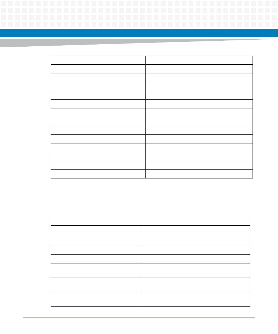
About this Manual
Abbreviation Definition
KVM Keyboard, Video, and Mouse
OOS Out of Service
PCI Peripheral Component Interconnect
PEM Power Entry Module
POST Power-On Self Test
RAID Redundant Arrays of Independent Disks
RTM Rear Transition Module
SAS Serial Attached Small Computer System Interface
SCSI Small Computer System Interface
SDR Sensor Data Record
SEL System Event Log
ShMC Shelf Management Controller
SOL Serial Over LAN
Conventions
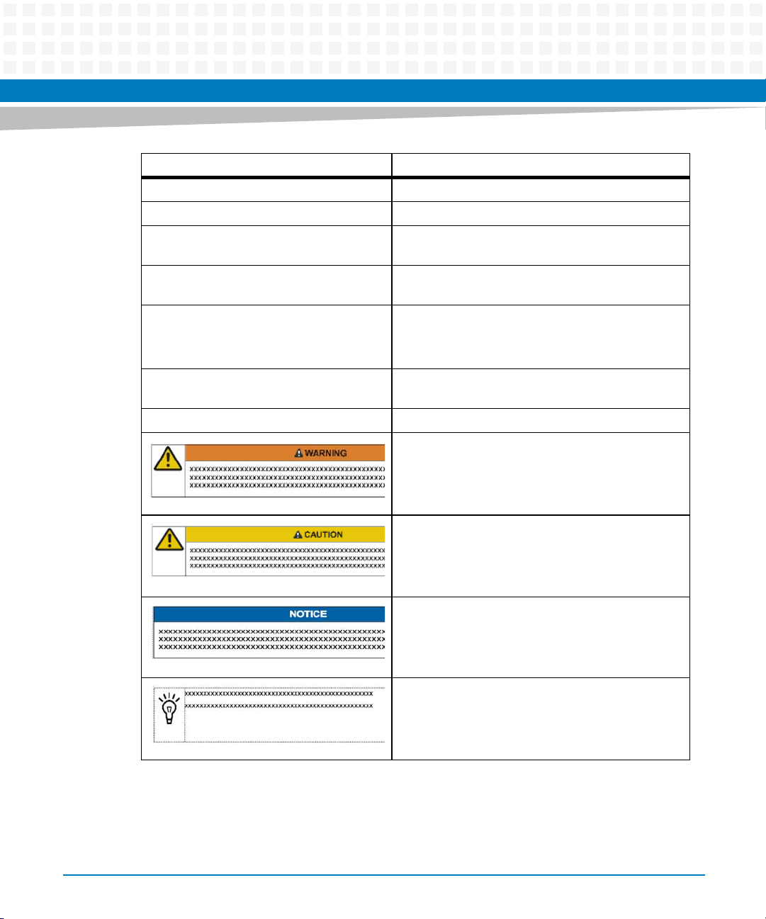
The following table describes the conventions used throughout this manual.
Notation Description
0x00000000 Typical notation for hexadecimal numbers (digits are
0b0000 Same for binary numbers (digits are 0 and 1)
bold Used to emphasize a word
Screen Used for on-screen output and code related elements
Courier + Bold Used to characterize user input and to separate it
Reference Used for references and for table and figure
0 through F), for example used for addresses and
offsets
or commands in body text
from system output
descriptions
ATCA-7350 Installation and Use (6806800G59G)
17
Page 18
About this Manual
Notation Description
File > Exit Notation for selecting a submenu
<text> Notation for variables and keys
[text] Notation for software buttons to click on the screen
... Repeated item for example node 1, node 2, ..., node
About this Manual
and parameter description
12
.
.
.
.. Ranges, for example: 0..4 means one of the integers
| Logical OR
Omission of information from example/command
that is not necessary at the time being
0,1,2,3, and 4 (used in registers)
Indicates a hazardous situation which, if not avoided,
could result in death or serious injury
Indicates a hazardous situation which, if not avoided,
may result in minor or moderate injury
Indicates a property damage message
No danger encountered. Pay attention to important
information
18
ATCA-7350 Installation and Use (6806800G59G)
Page 19
Summary of Changes
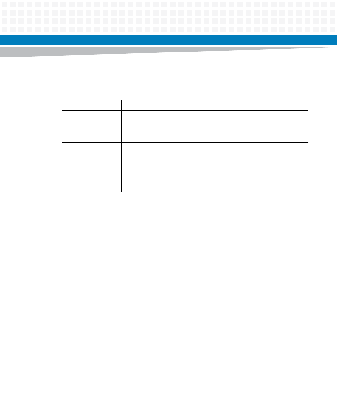
This manual has been revised and replaces all prior editions.
Part Number Publication Date Description
6806800G59A September 2008 First edition
6806800G59B November 2008 Second edition
6806800G59C January 2009 Added Chapter 9, Addressing, on page 167
6806800G59D January 2009 Fourth edition
6806800G59E February 2009 Fifth edition
6806800G59F February 2010 Updated section Standard Compliances on page
6806800G59G September 2014 Re-branded to Artesyn template.
About this Manual
24.
ATCA-7350 Installation and Use (6806800G59G)
19
Page 20

About this Manual
About this Manual
20
ATCA-7350 Installation and Use (6806800G59G)
Page 21

Introduction
1.1 Features
The ATCA-7350 server blade suite (hereinafter referred to as the ATCA-7350 suite) features the
capabilities of high speed calculation and mass data processing.
The ATCA-7350 suite consists of:
ATCA-7350
The ATCA-7350 is the short form for the ATCA-7350 server blade.
RTM-ATCA-7150
The RTM-ATCA-7150 is the short form for the RTM-ATCA-7150 rear transition module
(RTM) of the server blade.
RTM-ATCA-7350
The RTM-ATCA-7350 is the short form for the RTM-ATCA-7350 rear transition module
(RTM) of the server blade. This RTM enables 10Gb/sec Ethernet on the ATCA fabric
interface.
Chapter 1
You can install the ATCA-7350 in any node slot of your shelf. The RTM-ATCA-7x50 is installed in
the slot that is paired with the ATCA-7350 slot.
ATCA-7350 Installation and Use (6806800G59G)
21
Page 22
Introduction
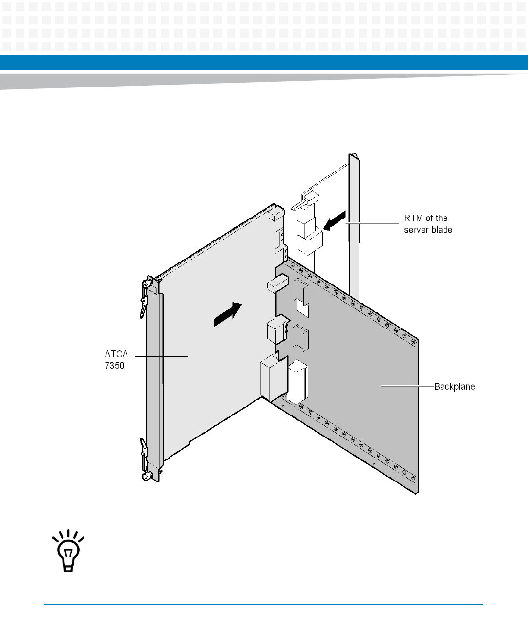
Figure 1-1 shows the connection between the ATCA-7350 and the RTM-ATCA-7x50.
Figure 1-1 Connection Between the ATCA-7350 and RTM-ATCA-7x50
22
The RTM-ATCA-7x50 is an accessory option that can be used for tailoring the ATCA-7350 to
specific applications.
The backplane is one part of the shelf. For details on the backplane and shelf, refer to the
respective system documentation.
ATCA-7350 Installation and Use (6806800G59G)
Page 23

Introduction
Table 1-1 lists the functions of the ATCA-7350.
Table 1-1 Functions of the ATCA-7350
Function Description
Processing functions Supports t wo quad-core LV Intel Xeon 5408 (2.13 GHz) processors
Supports 12 MB L2 cache
Supports up to four FB-DIMMs
Supports DIMM capacities of 512 MB, 1 GB, 2 GB, 4 GB, or 8 GB.
The maximum installed board memory capacity is 32 GB
Interface functions Provides 1GB onboard flash storage
Provides two SAS ports on the front panel
Provides two Ethernet Base interfaces (10/100/1000Base-T)
Provides two Ethernet Fabric interfaces (1000Base-BX, 10GBASE-
BX if RTM-ATCA7350 installed)
Provides one Ethernet Update Channel interface (1000Base-BX)
Provides two USB 2.0 interfaces (compatible with USB 1.1)
Provides serial port to access CPU and IPMC serial console
Provides two SAS on-board hard disks
The RTM-ATCA-7x50 that works with the ATCA-7350 provides a
monitor interface and a USB 1.1 interface. Through optional
daughter cards, the RTM can provide, 2 or 4 GE interfaces or 2 FC
interfaces. Only with RTM ATCA-7350 the system provides 10G
Ethernet on its fabric interfaces.
Management functions The ATCA-7350 provides the IPMC that is powered by system
management power. The IPMC is connected to the ShMC through the
redundant IPMB.
The IPMC provides the following functions:
Environmental sensors temperature, voltage
System Event Logs
Watchdog timer
Power-on, power-off, cold reset
SOL (Serial Over LAN)
FRU Hot-swap management
E-Keying control
ATCA-7350 Installation and Use (6806800G59G)
23
Page 24

Introduction
Table 1-1 Functions of the ATCA-7350 (continued)
Function Description
Integrated functions Gbit Ethernet controllers
IPMI
SAS storage controller
Video controller
1.2 Standard Compliances
The product is designed to meet the following standards.
Table 1-2 Standard Compliances
Standard Description
UL 60950-1
EN 60950-1
IEC 60950-1
CAN/CSA C22.2 No 60950-1
CISPR 22
CISPR 24
EN 55022
EN 55024
FCC Part 15
Industry Canada ICES-003
VCCI Japan
AS/NZS CISPR 22
EN 300 386
1
NEBS Standard GR-1089
CORE
NEBS Standard GR-63-CORE
ETSI EN 300019 series
2
PICMG
PICMG 3.1
IPMI 1.5
3.0
Legal safety requirements
EMC requirements (legal) on system level (predefined Artesyn
Embedded Computing System)
Environmental requirements
Defines mechanics, blade dimensions, power distribution, power
and data connectors, and system management
24
ATCA-7350 Installation and Use (6806800G59G)
Page 25
1. The blade does not fulfill the "Unpacked Equipment Shock Criteria" as defined in NEBS GR63 4.3.2. During tests
which consisted of dropping the blade from 100 mm height, we observed that on some blades the AdvancedTCA
zone 2 and 3 connectors got damaged. Although it was possible to manually repair the connectors and the blade was
fully functional again afterwards, the criteria imposed by the NEBS standard were not fulfilled.
2. Some PICMG requirements are not fully met. Refer ATCA-7350/RTM-ATCA-7350 Release Notes for more
information.
1.3 Ordering Information
When ordering board variants or board accessories, use the order numbers given on the
following pages.
1.3.1 Supported Board Models
The following table explains the product nomenclature used for the available board variants.
Introduction
Table 1-3 Product Nomenclature
Order Number Description
ATCA-7350-0GB
ATCA-7350-0GB-CK 1
RTM-ATCA-7350 RTM FOR THE ATCA-7350 BLADE WITH 10G FABRIC SUPPORT (ROHS 5/6)
RTM-ATCA-7350-GE RTM FOR THE ATCA-7350 BLADE WITH 2 GE INTERFACES (ROHS 5/6)
RTM-ATCA-7350-2GE RTM FOR THE ATCA-7350 BLADE WITH 4 GE INTERFACES (ROHS 5/6)
RTM-ATCA-7350-FC RTM FOR THE ATCA-7350 BLADE WITH 2 FC INTERFACES (ROHS 5/6)
RTM-ATCA-7150-GE RTM FOR THE ATCA-7150 BLADE WITH 2 GE INTERFACES (ROHS 5/6)
RTM-ATCA-7150-GE-FC RTM FOR THE ATCA-7150 BLADE WITH 2 GE AND 2 FC INTERFACES (ROHS 5/6)
MEZC-RTM-7150-GE MEZZANINE CARD WITH 2 GE INTERFACES (ROHS 5/6)
MEZC-RTM-7150-FC MEZZANINE CARD WITH 2 FC INTERFACES (ROHS 5/6)
ATCA-7x50-MEM-2G
ATCA-7x50-MEM-2G-F 1
ATCA-7x50-MEM-4G
ATCA-7x50-MEM-4G-F 1
ATCA-7350 Installation and Use (6806800G59G)
ATCA PROCESSOR BLADE, DUAL HARPERTOWN, QUAD CORE (2.13 GHZ),
0GB, 10G SUPPORT, 2 HDD/SSD SLOTS (ROHS 5/6)
2 GB FBD MEMORY MODULE FOR ATCA-7X50 (ROHS 6/6)
4 GB FBD MEMORY MODULE FOR ATCA-7X50 (ROHS 6/6)
25
Page 26

Introduction
Table 1-3 Product Nomenclature (continued)
Order Number Description
ATCA-7350-MEM-8G
ATCA-7350-MEM-8G-F 1
ATCA7x50-HDD1-SAS
ATCA7x50-HDD1-SAS-F 1
ATCA7x50-HDD2-SAS
ATCA7x50-HDD2-SAS-F 1
ATCA7x50-HDD3-SATA
ATCA7x50-HDD3-SATA-F 1
ATCA7x50-SSD2-SATA
ATCA7x50-SSD2-SATA-F 1
8 GB DUAL RANK FBD MEMORY MODULE FOR ATCA-7350 (ROHS 6/6)
72 GB SAS HDD FOR THE ATCA-7X50 (ROHS 6/6)
146 GB SAS HDD FOR THE ATCA-7X50 (ROHS 6/6)
80GB SATA HDD (EXT. TEMP.) FOR THE ATCA-7X50 (ROHS 6/6)
32 GB SATA SSD FOR THE ATCA-7X50 (ROHS 6/6)
1.3.2 Board Accessories
As of the printing date of this manual, the following board accessories were available:
Table 1-4 Available Board Accessories
Board Accessories Order Number
Gigabit Ethernet (GE) daughter card MEZC-RTM-7150-GE
Fiber Channel (FC) daughter card MEZC-RTM-7150-FC
Hard disk options ATCA7X50-HDD1-SAS
Solid state disk ATCA7X50-SSD2-SATA
Note: Board accessories are part of pre configured blade.
ATCA7X50-HDD1-SAS-F 1
ATCA7X50-HDD2-SAS
ATCA7X50-HDD2-SAS-F 1
ATCA7X50-HDD3-SATA
ATCA7X50-HDD3-SATA-F 1
ATCA7X50-SSD2-SATA-F 1
26
ATCA-7350 Installation and Use (6806800G59G)
Page 27
Hardware Preparation and Installation
2.1 Overview
This chapter describes:
Unpacking and inspecting the blade
Environmental and power requirements
Precautions during the operation
Checking the installation environment
Installing accessories
Installation and removal procedures
Ejector handles
Chapter 2
2.2 Unpacking and Inspecting the Blade
Damage of Circuits
Electrostatic discharge and incorrect installation and removal of the blade can damage
circuits or shorten their life.
Before touching the blade or electronic components, make sure that you are working in an
ESD-safe environment.
Shipment Inspection
To inspect the shipment, perform the following steps.
1. Verify that you have received all items of your shipment:
Printed Quick Start Guide
ATCA-7350 blade
Any optional items ordered
2. Check for damage and report any damage or differences to the customer service.
ATCA-7350 Installation and Use (6806800G59G)
27
Page 28

Hardware Preparation and Installation
3. Remove the desiccant bag shipped together with the blade and dispose of it
according to your country’s legislation.
The blade is thoroughly inspected before shipment. If any damage occurred during
transportation or any items are missing, please contact our customer's service immediately.
Unpacking the Blade
To unpack and check the ATCA-7350 suite, proceed as follows:
1. Wear the ESD-preventive wrist strap.
For more details, see Wearing the ESD-Preventive Wrist Strap on page 34.
2. Lay the packing carton according to the arrow direction on the cover.
3. Cut the tape to open the packing carton.
4. According to Table 2-1, check that the components are complete and in good condition,
without defects such as oxidation, chemical corrosion, missing component, or
transportation damage.
Table 2-1 List of Packing Items
SN Description
1 Packing materials, such as packing carton, plastic package, and foam
2 Documentation bag, containing documents shipped with the product
3 ATCA-7350, which can be used with an RTM-ATCA-7150 or RTM-ATCA-7350
But 10G Ethernet support is only available with RTM-ATCA-7350.
4 RTM-ATCA-7150 or RTM-ATCA-7350, which must be used with an ATCA-7350
5 Desiccant bag
28
ATCA-7350 Installation and Use (6806800G59G)
Page 29

Hardware Preparation and Installation
The actual items in the packing carton are decided by the contract.
If you do not order an RTM-ATCA-7x50, all functions provided by the RTM are not
available.
ATCA-7350 Installation and Use (6806800G59G)
29
Page 30

Hardware Preparation and Installation
2.3 Environmental and Power Requirements
The following environmental and power requirements are applicable to the blade.
2.3.1 Environmental Requirements
Table 2-2 Environmental Requirements
Requirement Operating Non-Operating
Temperature +5ºC (41ºF) to +40ºC (105ºF) (normal operation)
according to NEBS Standard GR-63-CORE
-5ºC to +55ºC (exceptional operation) according
to NEBS Standard GR-63-CORE
Temp. Change +/- 0.25ºC/min according to NEBS Standard GR-
63-CORE
1
-40ºC (-40ºF) to +70ºC
(158ºF).
+/- 0.25ºC/min
2
30
Rel. Humidity 5% to 85% non-condensing according to
Artesyn-internal environmental requirements
Altitude <=3000 m
Maximum
weight
Length x width x
height
Vibration
(tested in target
platform)
Shock Half-sine, 11 m/Sec, 30mSec/sec
4.0 kg
322.3 mm × 280 mm × 29 mm
1g from 5 to 100 Hz and back to 5 Hz at a rate of
0.25 octave/minute
3
2
ATCA-7350 Installation and Use (6806800G59G)
5% to 95% non-condensing
according to Artesyn-internal
environmental requirements
5-20 Hz at 0.01 g2/Hz
20-200 Hz at -3.0 dB/octave
2
Random 5-20 Hz at 1 m
Random 20-200 Hz at -3
2
m/Sec
Blade level packaging
Half-sine, 6 mSec at 180
2
m/Sec
/Sec
3
Page 31
Hardware Preparation and Installation
Table 2-2 Environmental Requirements (continued)
Requirement Operating Non-Operating
Free Fall 1,200 mm (Packaged) /all
edges and corners
1.0m (Packaged) per ETSI 300
019-2-2 (Blade level
packaging)
25 mm (unpackaged) per GR63-CORE
1. When operated in 55C ambient temperature and depending on the shelf's cooling capabilities the board is plugged
into, the SAS hard disk surface temperature exceeds the specified maximum limit of 60C.
2. The SAS drives can meet this max temperature range of non-operating.
3. The vibration tolerance can be further limited due to the hard disk you are installing on the blade. Please refer to the
respective datasheet for further information.
2.3.2 Power Requirements
Make sure that the blade is used in an AdvancedTCA shelf connected to -48VDC up to -60VDC,
according to Telecommunication Network Voltage (TNV-2). A TNV-2 circuit is a circuit whose
normal operating voltages exceed the limits for a safety-extra-low-voltage (SELV) under
normal operating conditions, and which is not subject to overvoltages from
telecommunication networks.
Table 2-3 lists the power requirements for the ATCA-7350.
Table 2-3 Power Requirements
Requirement Operating
Rated Voltage -48VDC to -60VDC
Operating Voltage -39.0VDC to -72VDC
Input Current 3.75A at 48V
Power Dissipation 200W (max) 150W (typical)
ATCA-7350 Installation and Use (6806800G59G)
US and Canada: -48VDC
US and Canada: -39.0 to -60VDC
31
Page 32
Hardware Preparation and Installation
The blade provides two independent power inputs according to the AdvancedTCA
specification.
2.4 Precautions
Electric Shock
There is current in the power cords and communication cables. Touching the connectors of
the power cords and communication cables may cause electric shock.
Do not touch the connectors of power cords and communication cables.
32
Electrostatic Discharge
Do not touch the circuit board with bare hands.
The static electricity of the human body may damage the electrostatic sensitive devices
(ESSDs) on the circuit board.
Make sure that you wear an electrostatic discharge (ESD)-preventive wrist strap or antistatic
glove to prevent the static electricity from hurting you or damaging the device.
Keep your personal objects such as your clothes away from the ATCA-7350 suite. To prevent
the static electricity from damaging the device, it is recommended to wear antistatic
clothes.
Pin Damage
If the blade is not fully aligned with the interface in the backplane, too much force may twist
the pins on the blade or backplane.
Do not exert too much force when you insert the blade.
ATCA-7350 Installation and Use (6806800G59G)
Page 33

Note the following points at the time of installing RTM-ATCA-7x50:
If an RTM is planned to be used, you must install the RTM in the slot before installing the
ATCA-7350 in the paired slot. If the ATCA-7350 is installed first and shelf power is turned
on the RTM must not be installed in the paired slot.
To take the ATCA-7350 suite, hold the captive screw on the top of the face plate with one
hand and the lower edge of the blade with the other hand. Do not touch the components
of the blade.
2.4.1 ESD Prevention
Static electricity may hurt you or damage the device. To minimize the damage, pay attention
to the following points:
Before you operate the device, wear the ESD-preventive wrist strap. Both terminals of the
ESD-preventive wrist strap must contact well. One terminal touches your bare skin, and
the other is inserted in the jack at the front or back side of the shelf. For details on how to
wear the ESD-preventive wrist strap, see Wearing the ESD-Preventive Wrist Strap on page 34.
Hardware Preparation and Installation
Avoid moving as much as possible. Movement gathers static electricity around you.
Do not touch the solder point, pin, or bare circuit.
Do not leave the device in the place where others can operate it.
Install the device at once after you take it out of the antistatic package. If you need to lay
down the device, place it back in the antistatic package. Do not lay the device on the shelf
or cabinet.
Monitor the temperature and humidity of the equipment room. Warm air decreases the
humidity but increases the static electricity in the room.
Damage of Circuits
Electrostatic discharge and incorrect module installation and removal can damage circuits or
shorten their life. Before touching the module or electronic components, make sure that you
are working in an ESD-safe environment.
ATCA-7350 Installation and Use (6806800G59G)
33
Page 34
Hardware Preparation and Installation
2.5 Checking the Installation Environment
Table 2-4 lists the environment for installing the ATCA-7350 suite.
Table 2-4 Environment for Installing the ATCA-7350 Suite
Item Description
Cabinet Cabinet that complies with the IEC297 standard
Note:
Leave enough space around the cabinet. Prevent air blocking of fans and
provide controlled ambient air at shelf air-inlet to ensure sufficient airflow and
appropriate heat exchange in the shelf.
Shelf Shelf of the system
Note:
Consider heat dissipation when you choose slots to install blades. If the shelf is
not fully configured, install the blades in scattered slots. Unoccupied slots
must be protected with appropriate blank filler blades to prevent air leaks.
2.5.1 Wearing the ESD-Preventive Wrist Strap
Product Damage
Electrostatic discharge can damage circuits or shorten their life.
The ESD-preventive wrist strap prevents only the static electricity on your body from
damaging the blade. To prevent the static electricity on your clothes, it is recommended to
wear the antistatic clothes. Additionally, you have to make sure that the cabinet and shelf are
properly grounded - for details, refer to the respective system documentation.
The cable of an ESD-preventive wrist strap is limited. In this case, before you wear the ESDpreventive wrist strap, place the device within 0.5 m away from the shelf.
34
ATCA-7350 Installation and Use (6806800G59G)
Page 35
Hardware Preparation and Installation
To wear the ESD-preventive wrist strap, proceed as follows:
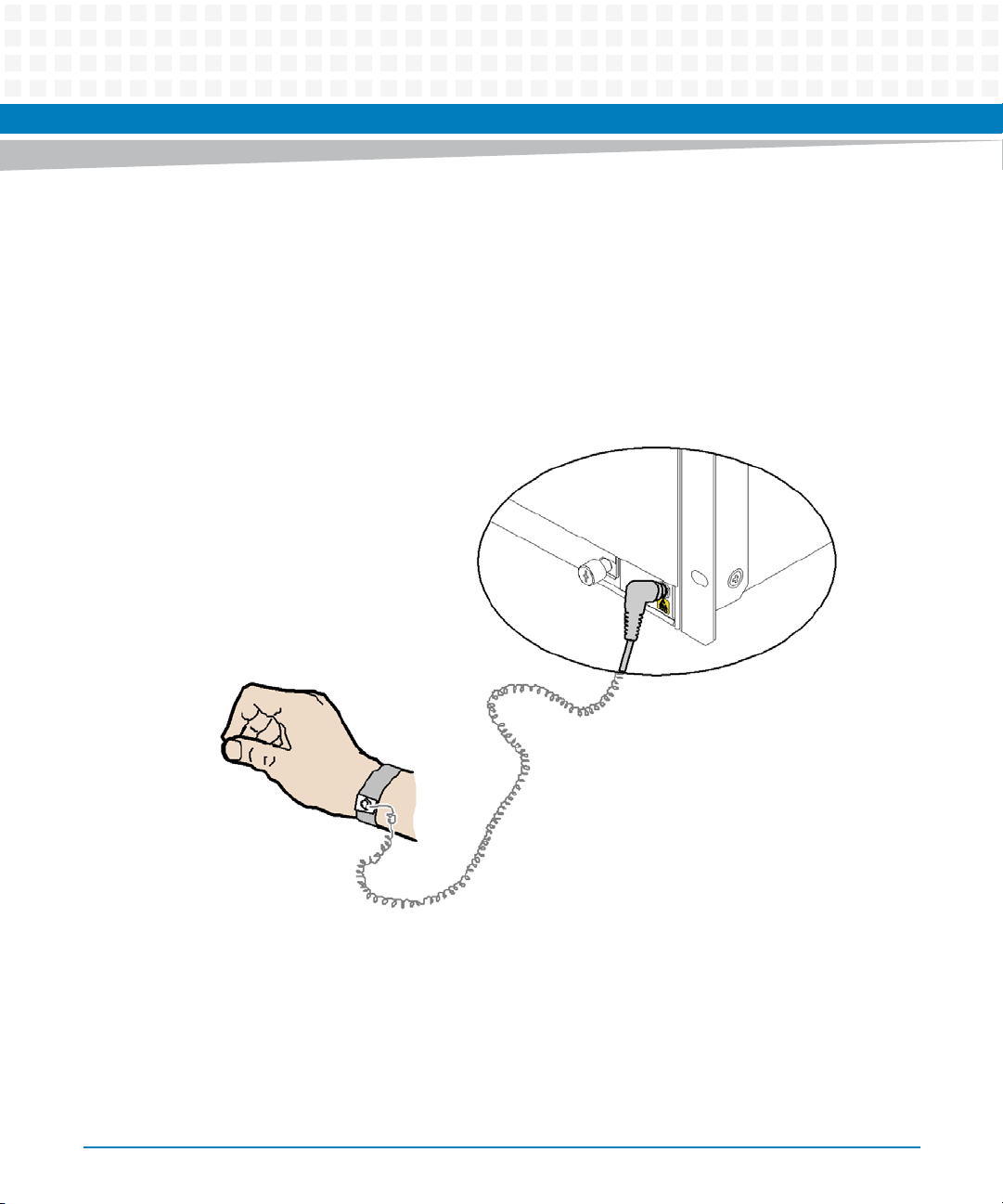
1. Wrap the ESD-preventive wrist strap around your wrist, as shown in Figure 2-1.
2. Fasten the latch. Make sure that the ESD-preventive wrist strap well touches your bare
wrist.
3. Insert the grounding terminal of the ESD-preventive wrist strap in the jack of the cabinet
or shelf.
Figure 2-1 Wearing the ESD-Preventive Wrist Strap
ATCA-7350 Installation and Use (6806800G59G)
35
Page 36

Hardware Preparation and Installation
2.5.2 Removing Blank Filler Blades
After you remove a blank filler blade, store it in the equipment room or a damp-proof
and dust-proof place.
After you remove a blade from the shelf, install a blank filler blade in vacant slot.
Otherwise, the functions such as ventilation, heat dissipation, electromagnetic shield,
and dust proof may be affected.
For a newly-delivered shelf, you can remove all blank filler blades and then install blades
in all slots when the shelf is not powered on.
If a shelf is powered on, you can remove a blank filler blade and then install a blade. In
this way, install multiple blades one by one.
36
ATCA-7350 Installation and Use (6806800G59G)
Page 37
Hardware Preparation and Installation
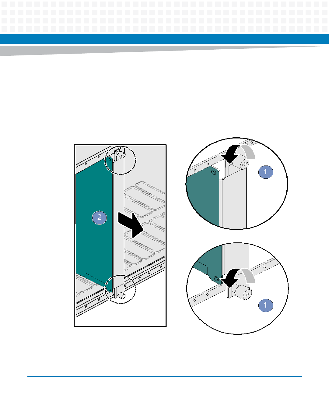
Before you install the ATCA-7350 suite, remove blank filler blades from installation slots as
follows:
1. Use a screwdriver anticlockwise to loosen the two captive screws on a blank filler blade, as
shown in Figure 2-2.
2. Pull the blank filler blade out of the slot, as shown in Figure 2-2.
Figure 2-2 Removing the Blank filler blade
ATCA-7350 Installation and Use (6806800G59G)
37
Page 38
Hardware Preparation and Installation
2.6 Installing Blade Accessories
2.6.1 Precautions
Electric Shock
There is current in the power cords and communication cables. Touching the connectors of
the power cords and communication cables may cause electric shock.
Do not touch the connectors of power cords and communication cables.
When you install or replace components, pay attention to the following points:
Wear the ESD-preventive wrist strap to prevent the static electricity from damaging the
device.
Keep the area where the components reside clean and keep the components away from
the heat generating devices, such as radiator.
Ensure that your sleeves are tightened or rolled up above the elbow. For safety purpose, it
is not recommended to wear jewelry, watch, glasses with metal frame, or clothes with
metal buttons.
Do not exert too much force, or insert or remove the components forcibly. Avoid damage
to the components or plug-ins.
38
ATCA-7350 Installation and Use (6806800G59G)
Page 39
Hardware Preparation and Installation
2.6.2 Optional Components Supported by the ATCA-7350
Only those who are certificated or authorized by Artesyn can replace or change the
components.
Table 2-5 lists the optional components supported by the ATCA-7350.
Table 2-5 Optional Components Supported by the ATCA-7350 Suite
Blade Supported Component
ATCA-7350 DIMM
Hard disk
Daughter cards on the RTM
For more information on the daughter cards, refer to RTM-ATCA-7x50 Installation and Use
Manual, MESC-RTM-7150-FC Installation Information, and MESC-RTM-7150-GE Installation
Information.
ATCA-7350 Installation and Use (6806800G59G)
39
Page 40

Hardware Preparation and Installation
2.6.3 Preparations
Before you install or replace the component, make the following preparations:
Confirming the feasibility of the operation
– There are available spare parts of the component to be installed or replaced in the
equipment warehouse. When the available spare parts are lacking, contact Artesyn
Embedded Technologies for help in time.
– Make sure that the new component is in good condition, without defects such as
oxidation, chemical corrosion, missing component, or transportation damage.
– By reading this document, you are familiar with how to install and replace the
component and master the skills required by the operation.
Checking the environment
Make sure that the shelf, power supply, temperature, and humidity meet the operating
requirement for the blades and components. For details, refer to the respective system
documentation.
40
Preparing spare parts and tools
– Prepare the component to be installed or replaced.
When you hold or transport the component, use the special antistatic package. Also,
you need to tidy, record, and repair the component during routine maintenance.
– Prepare the cross screwdriver, screws, plastic supports, cooling gel, and ESD-
preventive wrist strap.
The supplier provides a list of tools and negotiates with to decide the tool provider.
Confirming installation or changing position
Confirm the positions of the cabinet, the shelf, and the slot where the ATCA-7350 is
installed. Then, stick a label on the face plate of the ATCA-7350 to avoid wrong operation.
Others
If a serious problem occurs and cannot be solved when you install or replace the
component, contact Artesyn for technical support.
ATCA-7350 Installation and Use (6806800G59G)
Page 41

2.6.4 DIMM
When you install or replace the DIMM, pay attention to the following points:
The ATCA-7350 provides four DIMM interfaces and supports the DIMM with a capacity of
512 MB, 1 GB, 2 GB, 4 GB, or 8 GB.
The DIMMs must have the same size, frequency, type, and technology, physical design and
manufacturer.
DIMMs must be of single or dual rank type. Quad rank types are not supported.
If the selected memory configuration does not require population of all available DIMM
slots, install the required DIMMs as follows:
– If one DIMM is configured, install it in DIMM slot 0.
– If two DIMMs are configured, install them in DIMM slots 0 and 1.
– Configuring three DIMMs is not supported.
Hardware Preparation and Installation
ATCA-7350 Installation and Use (6806800G59G)
41
Page 42
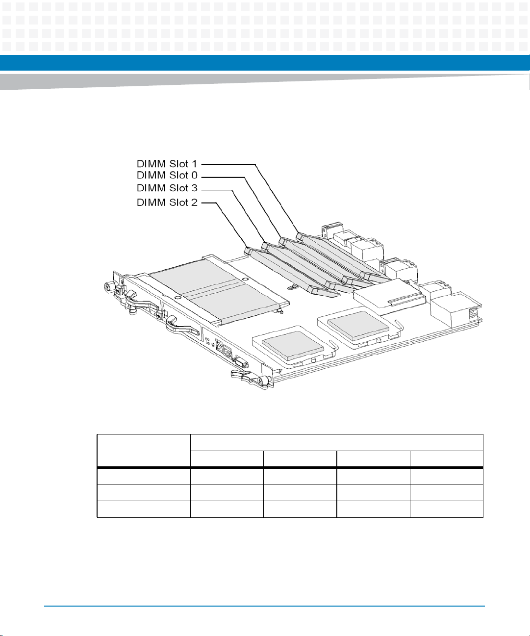
Hardware Preparation and Installation
Figure 2-3 shows the positions of the DIMM interfaces on the ATCA-7350.
Figure 2-3 Positions of the DIMM Interfaces
Table 2-6 DIMM Configuration on the ATCA-7350
Number of DIMMs
1x
2xx
4xxxx
2.6.4.1 Installing the DIMM
To install the DIMM, proceed as follows:
1. Wear the ESD-preventive wrist strap.
For details, see Wearing the ESD-Preventive Wrist Strap on page 34.
42
Installation Positions
DIMM Slot0 DIMM Slot1 DIMM Slot2 DIMM Slot3
ATCA-7350 Installation and Use (6806800G59G)
Page 43
Hardware Preparation and Installation
2. Lay the ATCA-7350 where the DIMM is to be installed on the antistatic desktop.
3. Take the DIMM out of the antistatic package.
4. Make sure that the two interface fixing clips of the DIMM socket are fully open. Adjust the
DIMM to align it with the DIMM socket.
Product Damage
Operate the fixing clips slightly to avoid breaking them or damaging the DIMM socket.
5. Insert the DIMM in the socket along the guide rails, as shown in Figure 2-4.
If there is a gap between the DIMM and the fixing clips, the DIMM is not installed properly. In
this case, open the fixing clips and remove the DIMM. Then, insert the DIMM again.
6. Make sure that the fixing clips are fastened or closed firmly as shown in Figure 2-4.
ATCA-7350 Installation and Use (6806800G59G)
43
Page 44
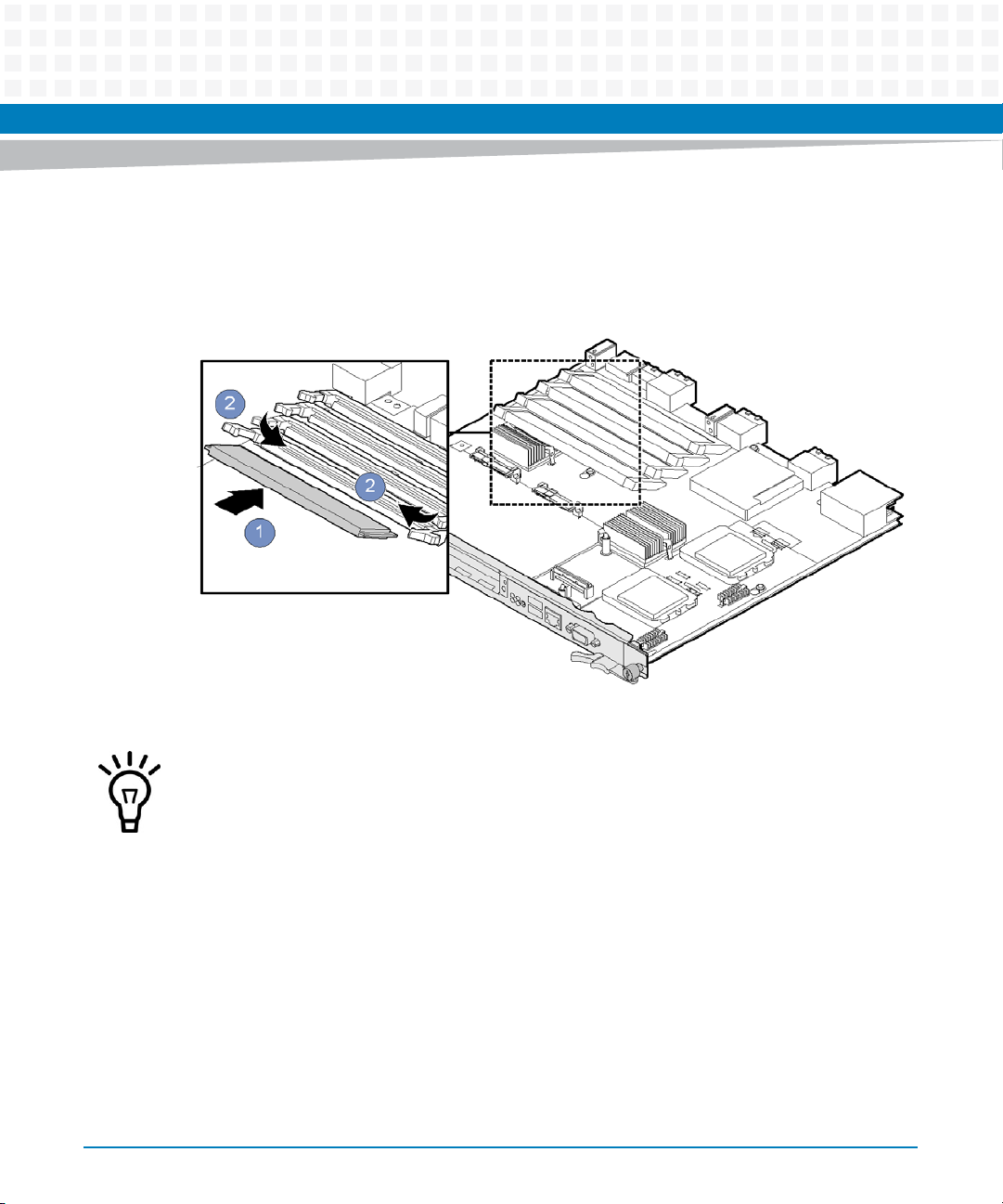
Hardware Preparation and Installation
7. Insert the ATCA-7350 with the DIMM installed in the shelf.
For details, see Installing the ATCA-7350 in a Powered Shelf on page 51.
Figure 2-4 Installing the DIMM
You can install the DIMMs in all DIMM sockets in the same way.
After installation, insert the ATCA-7350 in the shelf and power on the ATCA-7350. Check
whether the OS can be loaded properly. If it can be, in the OS, check whether the displayed
memory capacity is consistent with the actual one.
2.6.4.2 Replacing the DIMM
To replace the DIMM, proceed as follows:
1. Wear the ESD-preventive wrist strap.
For details, see Wearing the ESD-Preventive Wrist Strap on page 34.
44
ATCA-7350 Installation and Use (6806800G59G)
Page 45
Hardware Preparation and Installation
2. Remove the ATCA-7350 whose DIMM is to be replaced.
For details, see Removing the ATCA-7350 on page 55.
Product Damage
To avoid breaking them or damaging the DIMM sockets, do not exert too much force to
operate the fixing clips.
If you open the two fixing clips of the DIMM at the same time, the DIMM bounces from
the interface. Operate the fixing clips carefully to avoid damaging the DIMM.
3. Open one fixing clip of the DIMM carefully until the DIMM rises from the interface. Hold the
top edge of the DIMM and open the other fixing clip carefully until the DIMM is removed
from the interface, as shown in Figure 2-5.
4. Take the DIMM out of the socket carefully, as shown in Figure 2-5.
5. Place the extracted DIMM in the antistatic package.
6. Take the new DIMM out of the antistatic package.
7. Install the new DIMM.
For details, see Installing the DIMM on page 42.
ATCA-7350 Installation and Use (6806800G59G)
45
Page 46
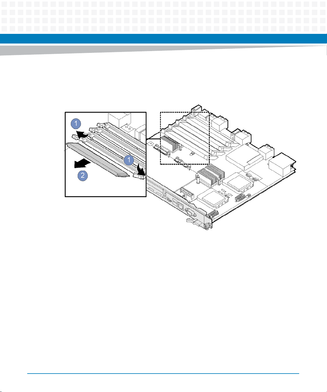
Hardware Preparation and Installation
8. Install the ATCA-7350 with the DIMM replaced.
For details, see Installing the ATCA-7350 in a Powered Shelf on page 51.
Figure 2-5 Removing the DIMM
After replacement, check whether the OS can be loaded properly. If it can be, in the OS, check
whether the displayed memory capacity is consistent with the actual one.
2.6.5 Hard Disk
This section describes how to install and replace the hard disk on the ATCA-7350.
2.6.5.1 Installing the Hard Disk
For more information on the installation of the hard disk, refer to the HDD Installation Sheet.
To install the hard disk, proceed as follows:
1. Wear the ESD-preventive wrist strap.
For details, see Wearing the ESD-Preventive Wrist Strap on page 34.
2. Take the hard disk to be installed out of the antistatic package.
46
ATCA-7350 Installation and Use (6806800G59G)
Page 47

Hardware Preparation and Installation
3. Exert even force to push the hard disk smoothly in the hard disk holder. Align the screw
holes at the sides of the hard disk with those at the sides of the holder, as shown in Figure
2-6.
4. Use the screwdriver to fasten the four screws clockwise to fix the hard disk, as shown in
Figure 2-6.
5. Exert even force to push the hard disk in the fixing bracket on the ATCA-7350, as shown in
Figure 2-6.
6. Insert the ATCA-7350 with the hard disk installed in the shelf if not already installed in the
system.
For details, see Installing the ATCA-7350 in a Powered Shelf on page 51.
You can install the other hard disk in the same way.
ATCA-7350 Installation and Use (6806800G59G)
47
Page 48
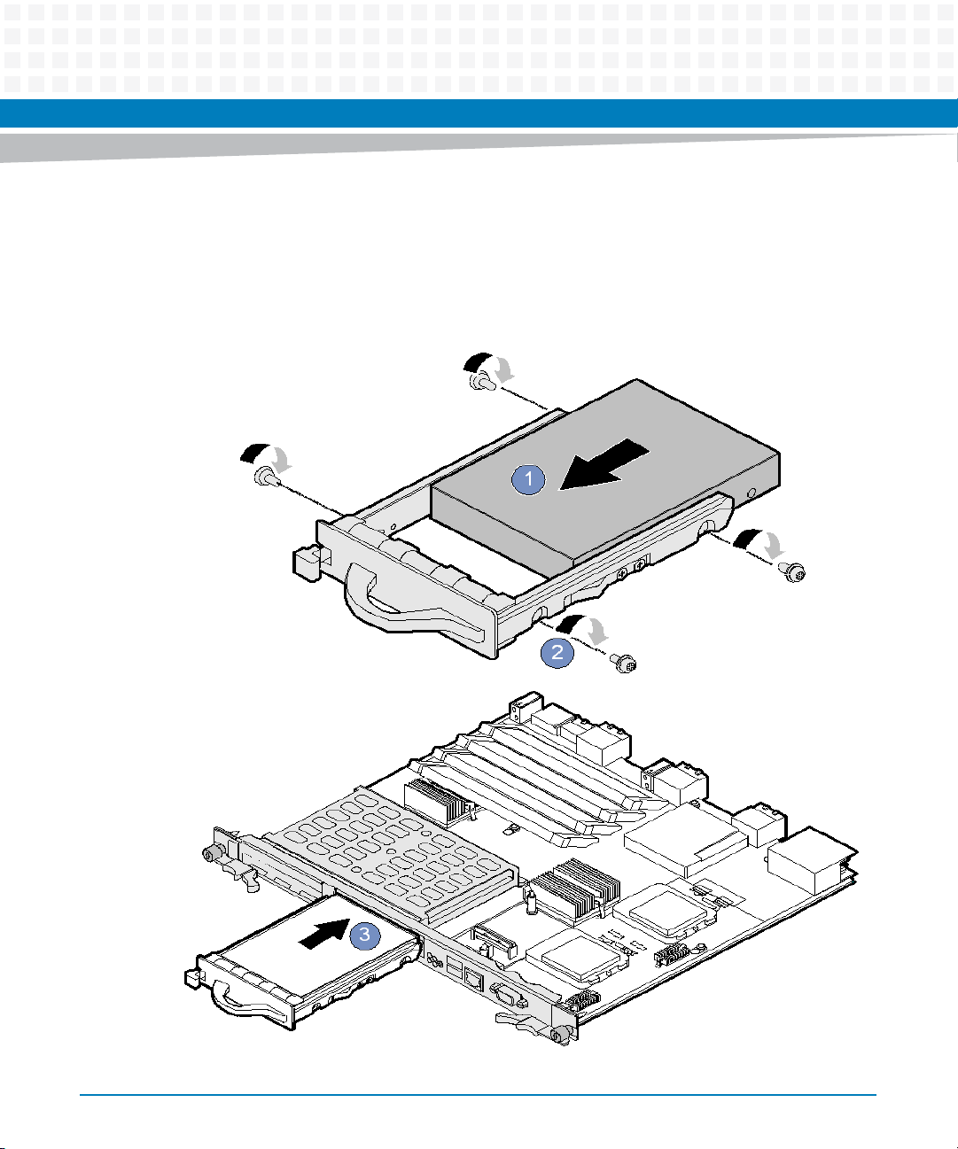
Hardware Preparation and Installation
After installation, check whether the ATCA-7350 can be powered on and work normally or
continuous to operate normally after the drive hot-swap. Check whether the data in the hard
disk can be read and written normally. See section RAID Operations and Disk Hot-swap for
further required steps.
Figure 2-6 Installing the Hard Disk
48
ATCA-7350 Installation and Use (6806800G59G)
Page 49

2.6.5.2 Replacing the Hard Disk
To replace the hard disk, proceed as follows:
1. Wear the ESD-preventive wrist strap.
For details, see Wearing the ESD-Preventive Wrist Strap on page 34.
2. Remove the ATCA-7350 whose hard disk is to be replaced if the blade is powered down.
Keep the ATCA-7350 in the occupied slot and keep the ATCA handles closed if the hard disk
shall be replaced by hot-swap. See Chapter 7, RAID 1 Operations, on page 135 for required
steps to perform the disk hot-swap.
For details, see Removing the ATCA-7350 on page 55.
3. Remove the finger on the hard disk holder in a direction as shown in Figure 2-7 to unlock
the hard disk.
4. Exert even force to pull the hard disk holder from the fixing bracket, as shown in Figure 2-7.
5. Unfasten the four screws used to fasten the hard disk anticlockwise, as shown in Figure 2-7.
Hardware Preparation and Installation
6. Exert even force to pull the hard disk from the holder, as shown in Figure 2-7.
7. Place the extracted hard disk in the antistatic package.
8. Take the new hard disk out of the antistatic package.
9. Install the new hard disk.
For details, see Installing the Hard Disk on page 46.
10. Install the ATCA-7350 with the hard disk replaced if not already installed in the system.
For details, see Installing the ATCA-7350 in a Powered Shelf on page 51.
ATCA-7350 Installation and Use (6806800G59G)
49
Page 50
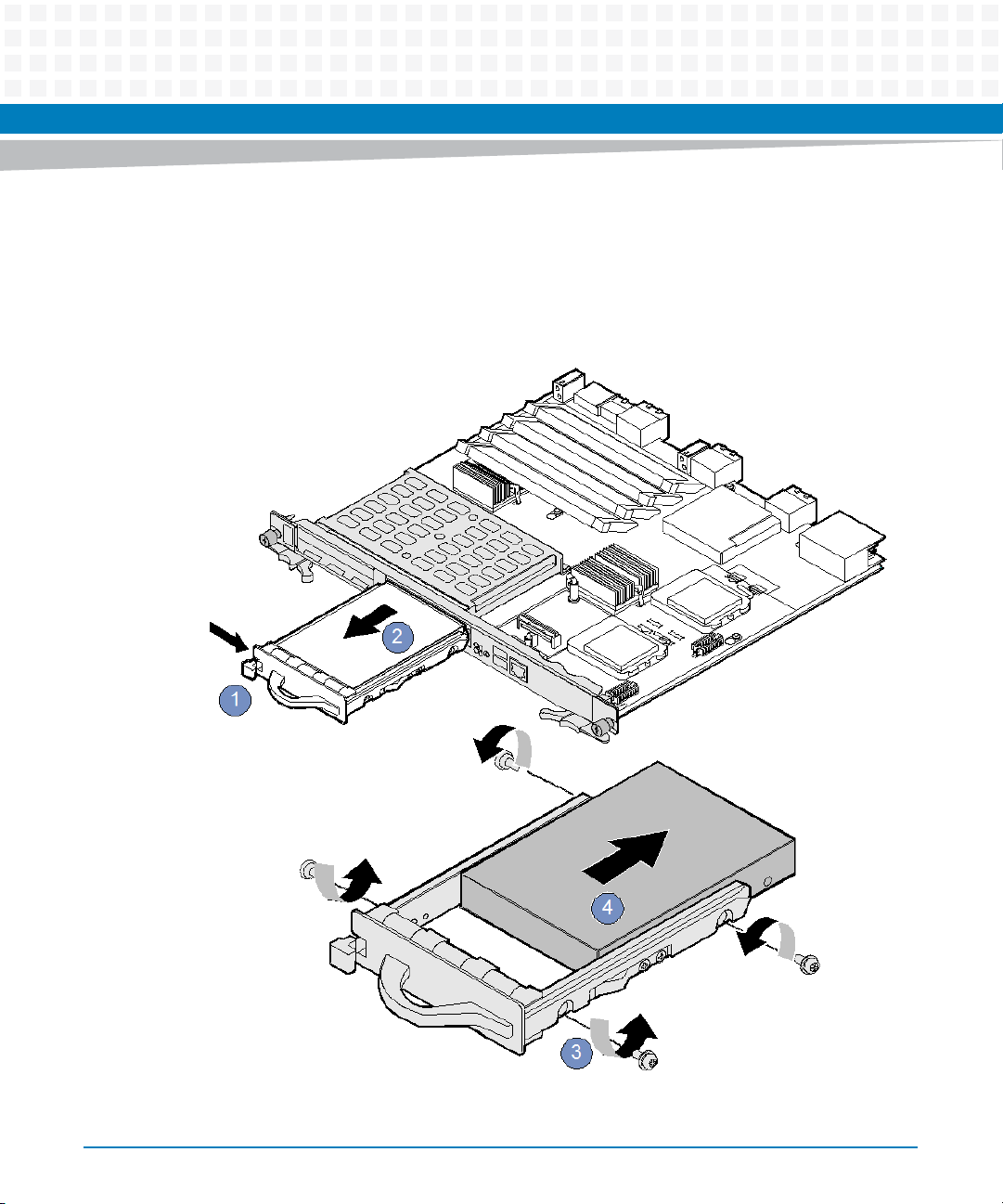
Hardware Preparation and Installation
After replacement, check whether the ATCA-7350 can be powered on and work normally or
continuous to operate normally after the drive hot-swap. Check whether the data in the hard
disk can be read and written normally. See Chapter 7, RAID 1 Operations, on page 135 for further
required steps.
Figure 2-7 Removing the Hard Disk
50
ATCA-7350 Installation and Use (6806800G59G)
Page 51

Hardware Preparation and Installation
2.7 Installing and Removing the Blade
2.7.1 Installation
RTM-ATCA-7x50 must be installed before the ATCA-7350 to avoid product damage. For more
information on RTM-ATCA-7x50, refer to RTM-ATCA-7150 Installation and Use manual and RTM-
ATCA-7350 Installation and Use manual.
2.7.1.1 Installing the ATCA-7350 in a Powered Shelf
The following procedure describes the installation of the blade. It assumes that your system is
powered. If your system is unpowered, you can disregard the blue LED and thus skip the
respective step. In this case it is a purely mechanical installation.
1. Wear the ESD-preventive wrist strap.
For details, see Wearing the ESD-Preventive Wrist Strap on page 34
2. Take the ATCA-7350 out of the antistatic package.
3. Fully open the upper and lower ejector handles.
4. Slide the ATCA-7350 along the guide rails until the positioning pins of the ATCA-7350 are
inserted in the positioning holes in the shelf, as shown in Figure 2-8.
5. Make sure that the upper and lower ejector handles are attached to the beam properly.
Close the upper and lower ejector handles until the inner sides of the ejector handles are
attached to the face plate, as shown in Figure 2-8. After closing the handles, the blue LED,
OOS and IS LEDs blink. When payload is powered on, the blue LED is continuously
illuminated, and the OOS and IS LEDs are out.
6. User the screwdriver to clockwise fasten the screws to fix the ATCA-7350, as shown in
Figure 2-8.
ATCA-7350 Installation and Use (6806800G59G)
51
Page 52
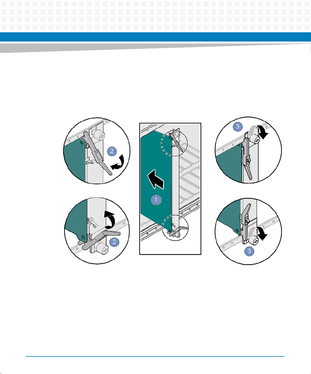
Hardware Preparation and Installation
7. Fully open the ejector handles and the ATCA-7350 is ready for power-on. Before you power
on the ATCA-7350, connect the required external cables and check that the ATCA-7350 is
installed properly.
For the details on how to power on the ATCA-7350, see Blade Power-On on page 53.
Figure 2-8 Installing the ATCA-7350
2.7.1.2 Checking the Installation
After you install the RTM-ATCA-7x50 and ATCA-7350, and connect and bind cables, check
whether:
The ATCA-7350 and RTM are installed in the paired slots.
The upper and lower ejector handles of the RTM are fully closed.
The cables are properly connected.
The cables are well bound.
52
ATCA-7350 Installation and Use (6806800G59G)
Page 53

2.7.1.3 Blade Power-On
The RTM-ATCA-7x50 is powered by the ATCA-7350 in the slot paired with the RTM slot. The
RTM-ATCA-7x50 does not support hot swap. Therefore, the RTM must be installed in the slot
before the ATCA-7350 is powered or shelf power is turned on.
2.7.1.3.1 Checks Before Blade Power-On
Before power-on, you need to confirm that:
The RTM-ATCA-7x50 and SMM are installed properly.
The shelf and SMM are powered on properly.
Hardware Preparation and Installation
The required external cables are connected.
The upper and lower ejector handles of the ATCA-7350 are opened.
2.7.1.3.2 Procedure
To power on the ATCA-7350, proceed as follows:
1. Wear the ESD-preventive wrist strap.
For details, see Wearing the ESD-Preventive Wrist Strap on page 34.
2. Close the upper and lower ejector handles.
The HOTSWAP LED blinks at the short blink rate. The OOS and IS LEDs blink for 10 times at
the same time. When the OOS is on (red) and the HOTSWAP LED is off, the ATCA-7350 is
powered on properly.
Payload Management software is responsible for controlling the OOS and IS LED.
ATCA-7350 Installation and Use (6806800G59G)
53
Page 54
Hardware Preparation and Installation
2.7.2 Removal
Before you remove an ATCA-7350 or RTM-ATCA-7x50, prepare packing materials, such
as an antistatic package.
Before you remove an ATCA-7350 or RTM-ATCA-7x50, power off the ATCA-7350. For
details on how to power off the ATCA-7350, see Power Off on page 54.
2.7.2.1 Power Off
The RTM-ATCA-7x50 is powered by the ATCA-7350 in the slot paired with the RTM slot. The
RTM-ATCA-7x50 does not support hot swap. You can remove the RTM only when the ATCA7350 is powered off or if the shelf power is off.
2.7.2.1.1 Checks Before Power-Off
Before power-off, you need to confirm that:
Data has been saved on the ATCA-7350.
No application runs on the ATCA-7350.
The ATCA-7350 has quitted the operating system (OS).
2.7.2.1.2 Procedure
To power off the ATCA-7350, proceed as follows:
1. Wear the ESD-preventive wrist strap.
For details, see Wearing the ESD-Preventive Wrist Strap on page 34.
54
ATCA-7350 Installation and Use (6806800G59G)
Page 55

2. Open the upper and lower ejector handles.
The ATCA-7350 is powered off properly when:
The HOTSWAP LED blinks at the short blink rate and then is on (blue).
The OOS LED is on (red) if it is in local control state.
The IS LED is off if it is in local control state.
2.7.2.2 Removing the ATCA-7350
To remove the ATCA-7350, proceed as follows:
1. Wear the ESD-preventive wrist strap.
For details, see Wearing the ESD-Preventive Wrist Strap on page 34.
2. Open the upper and lower ejector handles to power off the ATCA-7350, as shown in Figure
2-9.
For details, see Power Off on page 54.
Hardware Preparation and Installation
3. Use the screwdriver to unfasten the captive screws anticlockwise, as shown in Figure 2-9.
ATCA-7350 Installation and Use (6806800G59G)
55
Page 56
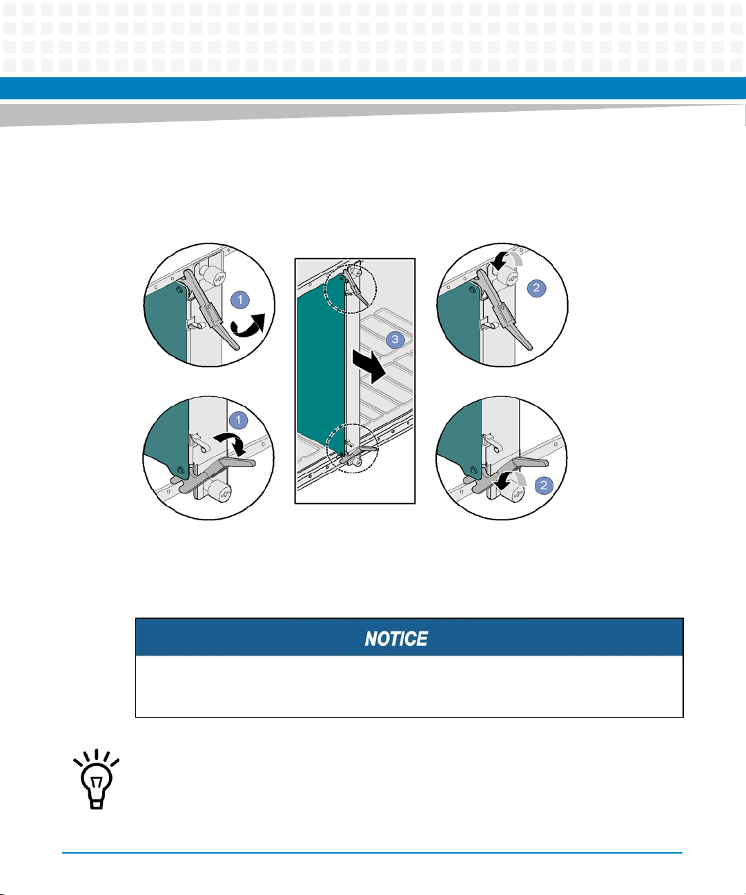
Hardware Preparation and Installation
4. Remove the ATCA-7350 along the guide rails, as shown in Figure 2-9.
5. Place the ATCA-7350 in the antistatic package.
Figure 2-9 Removing the ATCA-7350
2.7.2.3 Removing the RTM-ATCA-7x50
Product Damage
You should power off the front blade before removing RTM-ATCA-7x50.
For details on how to power off the front blade, refer to the respective system documentation.
56
ATCA-7350 Installation and Use (6806800G59G)
Page 57
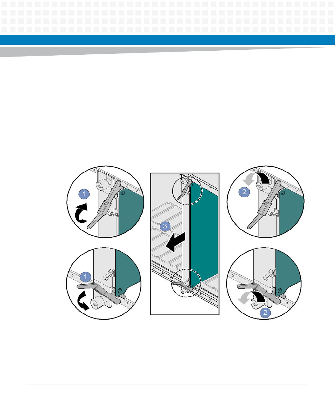
Hardware Preparation and Installation
To remove RTM-ATCA-7x50, proceed as follows:
1. Wear the ESD-preventive wrist strap.
For details, see Wearing the ESD-Preventive Wrist Strap on page 34.
2. Use the screwdriver to unfasten the captive screws anticlockwise, as shown in Figure 2-10.
3. Fully open the upper and lower ejector handles, as shown in Figure 2-10.
4. Remove RTM-ATCA-7x50 along the guide rails, as shown in Figure 2-10.
5. Place RTM-ATCA-7x50 in the antistatic package.
Figure 2-10 Removing RTM-ATCA-7x50
For more information refer to the RTM-ATCA-7150 Installation and Use manual and RTM-ATCA-
7350 Installation and Use manual.
ATCA-7350 Installation and Use (6806800G59G)
57
Page 58

Hardware Preparation and Installation
58
ATCA-7350 Installation and Use (6806800G59G)
Page 59
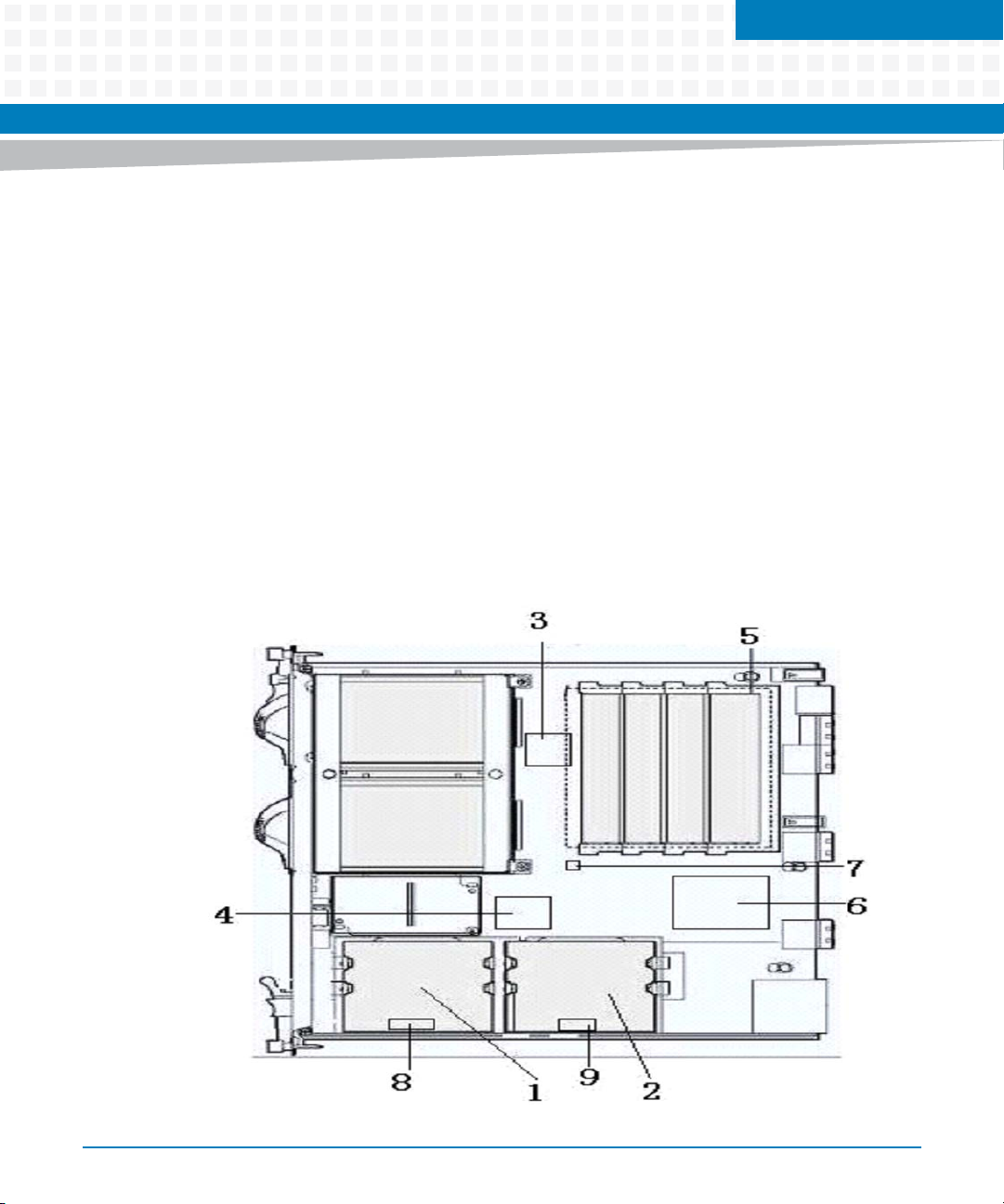
Controls, LEDs and Connectors
3.1 Overview
This chapter describes:
Blade layout
Face plate
Connectors
LEDs
3.2 Blade Layout
Figure 3-1 shows the components of the ATCA-7350.
Chapter 3
Figure 3-1 Components of the ATCA-7350
ATCA-7350 Installation and Use (6806800G59G)
59
Page 60

Controls, LEDs and Connectors
Table 3-1 lists the components of the ATCA-7350.
Table 3-1 Components of the ATCA-7350
Location Component Description
1, 2 Processor The ATCA-7350 uses the Intel quad-core LV Xeon processor,
3 I/O Controller Hub Intel 631xESB/632xESB.
4 MCH Intel 5000 Series Chipset Memory
5 DIMM's Up to 4 DIMM's are supported.
6 power converter 48V-
12V
7 DC/DC converter 12V-
3.3V
with low power consumption.
Controller Hub
8 Voltage Regulator of cpu
9 Voltage Regulator of cpu
60
ATCA-7350 Installation and Use (6806800G59G)
Page 61
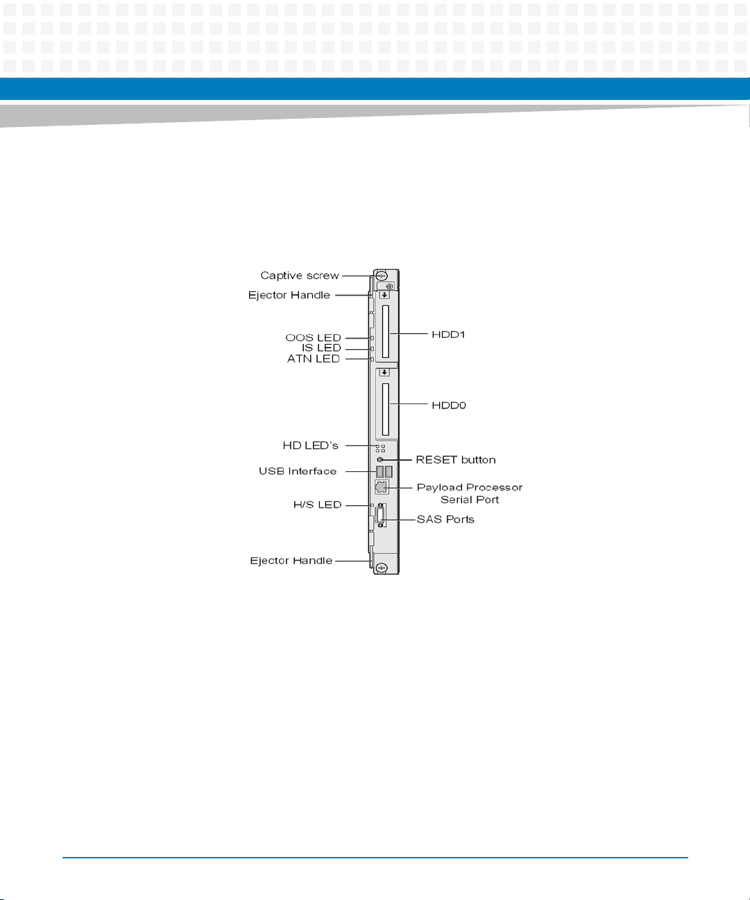
3.3 Face Plate
Figure 3-2 shows the face plate of the ATCA-7350.
Figure 3-2 Face Plate of the ATCA-7350
Controls, LEDs and Connectors
3.4 Connectors
Connectors along the rear edge of ATCA server blades are divided into three distinct zones, as
described in Section 2.3 of the PICMG 3.0 Specification:
Zone 1 for system management and power distribution
Zone 2 for data transport
Zone 3 for the rear transition module
On the ATCA-7350, Zone 2 is composed of two connectors P20 and P23. In addition, the ATCA7350 uses update channel interfaces defined in P20, as well as Base interfaces and Fabric
interfaces defined in P23.
ATCA-7350 Installation and Use (6806800G59G)
61
Page 62
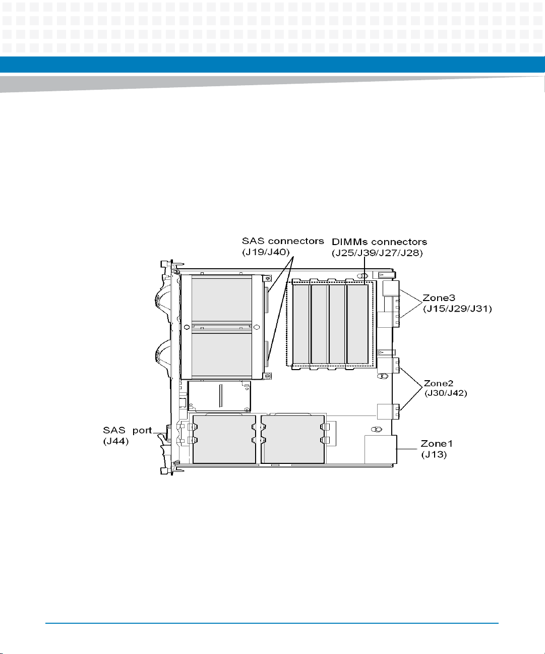
Controls, LEDs and Connectors
The face plate of the ATCA-7350 provides:
Two USB interfaces
Two 2.5 inch SAS hard disk drive bays
One RJ-45 serial port
One SAS Connector
Figure 3-3 On-Board Connectors
62
ATCA-7350 Installation and Use (6806800G59G)
Page 63
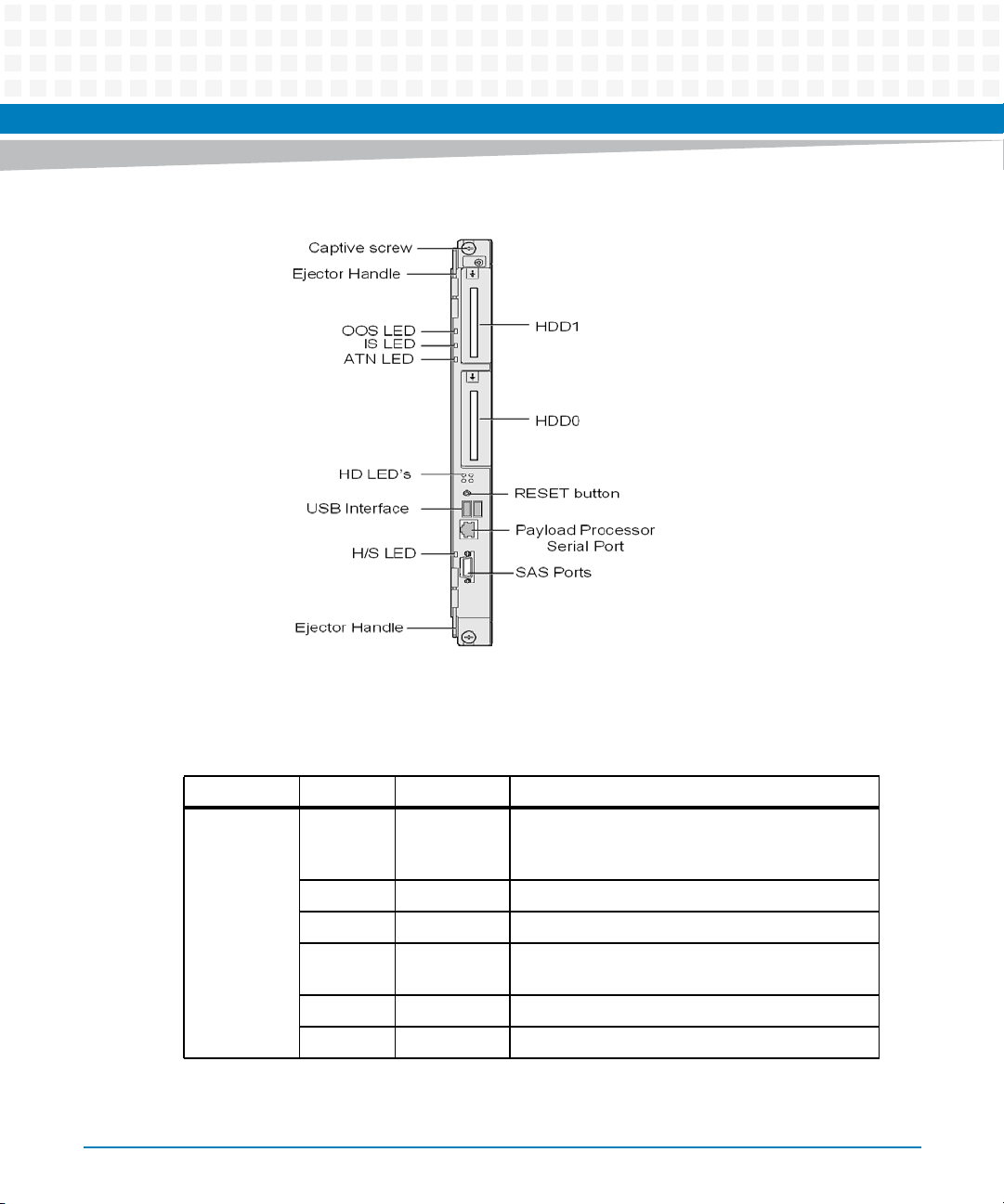
Figure 3-4 Face Plate Connectors
Controls, LEDs and Connectors
Table 3-2 lists the locations and description of all connectors on the ATCA-7350.
Table 3-2 Positions and Description of the Connectors of the ATCA-7350
Location REFDES Description Details
Back plane
Connectors
ATCA-7350 Installation and Use (6806800G59G)
J13 Zone1 (P10) 34-Pin, dual redundant -48 VDC power, metallic
J42 Zone2 (P20) 8*10-Pin, Update channel GE interface
J30 Zone2 (P23) 8*10-Pin, Base & Fabric Interfaces
J15 Zone3 5*11-Pin, RTM Power supply, KVM, IPMC RTM
J29 Zone3 4*10-Pin, PCI-E 4X channel, Fabric Port 1
J31 Zone3 8*10-Pin, 3 PCI-E 4X channels, Fabric Port 3
test, ringing generator, Shelf management
system connections, and Hardware Addressing
management
63
Page 64
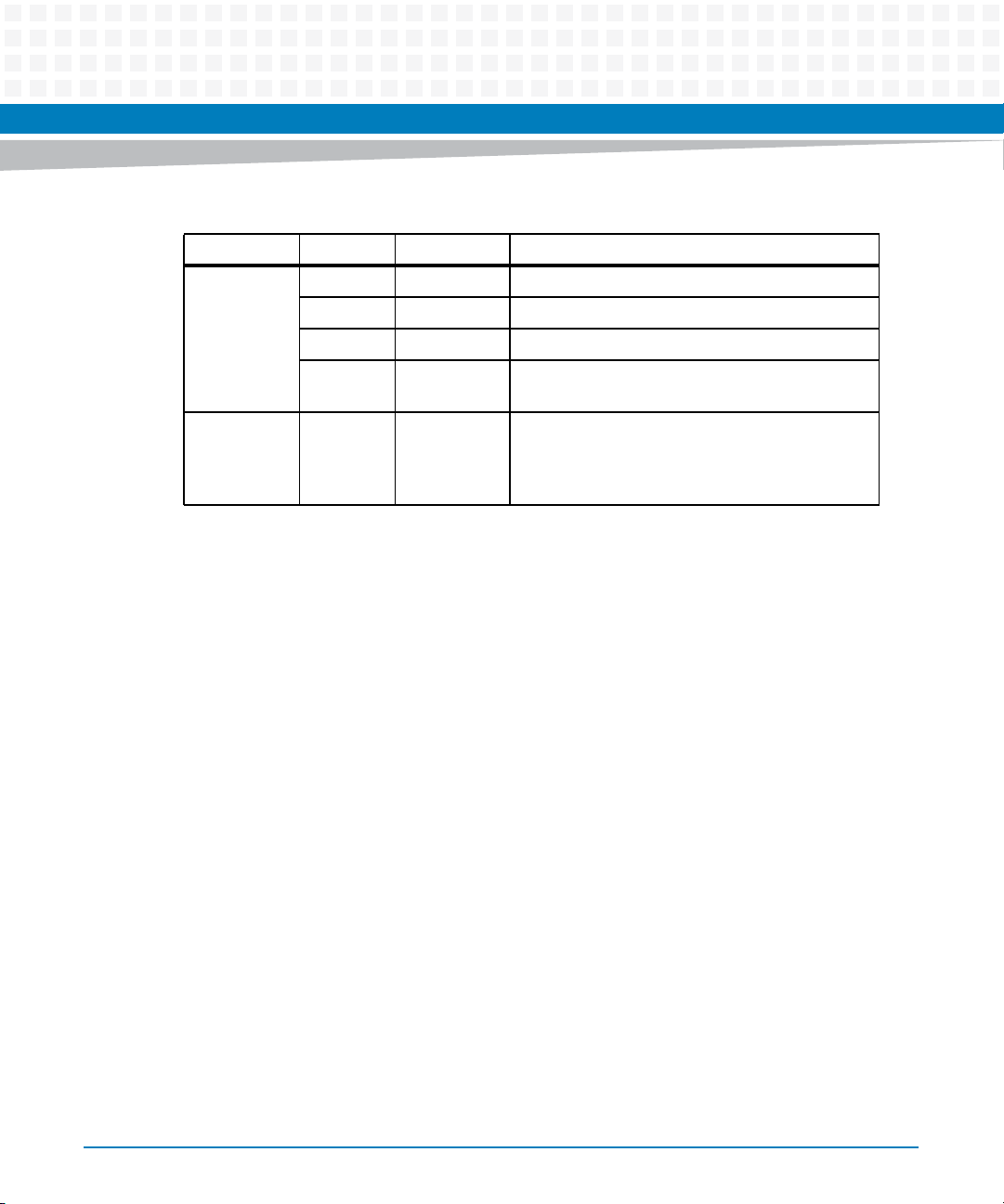
Controls, LEDs and Connectors
Table 3-2 Positions and Description of the Connectors of the ATCA-7350 (continued)
Location REFDES Description Details
Face Plate
Connectors
J19/J40 Drive Bay 1/0 29-Pin, SAS Connector
J14 USB 8-Pin, Dual USB port connector
J22 COM 8-Pin, RJ45 Serial port connector
On-Board
Memory
Module
Connectors
J44 SAS
Connector
J25/J39/J2
7/J28
FBD
Connectors
16-Pin, InfiniBand receptacle
240-Pin, Fully buffered DIMM slots
3.4.1 Backplane Connectors
3.4.1.1 Zone1 (P10) Power connector
The definition of the Zone 1 (P10) connector complies with PIGMIG 3.0.
3.4.1.2 Zone2 Data Transport ZD connector
The definition of the Zone 2 connector is a subset of that defined in PIGMIG3.0. The ATCA-7350
supports the update channel interface on P20, as well as the Base interface and Fabric interface
on P23 only.
The ATCA-7350 supports one Update channel connecting to the redundant slot. This channel
is on the P20 connector, which is Port 0 defined in PICMIG3.0. PICMIG3.0 defines five Update
ports in total. The other four ports are reserved. Reserved ports are terminated.
64
ATCA-7350 Installation and Use (6806800G59G)
Page 65
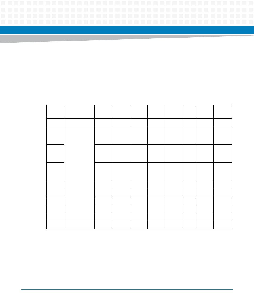
Controls, LEDs and Connectors
The connector pin assignments are described in the table as below with signals having the
following naming convention: UP(m)Tx/ Rx p, where:
Tx/Rx = transmit/receive
m = Channel designator (1-4)
p = polarity (+,-)
Table 3-3 J20/P20 Connector Pin Assignments for ATCA-7350
Interface
Pin
1 CLKs NC. NC. NC. NC. NC. NC. NC. NC.
Designation A B C D E F G H
2 Update
Channel
3NC.NC.Term.
4 UP(0)Tx+UP(0)Tx-UP(0)Rx+UP(0)Rx-NC. NC. Term.
5Fabric
6 NC. NC. NC. NC. NC. NC. NC. NC.
7 NC. NC. NC. NC. NC. NC. NC. NC.
8 NC. NC. NC. NC. NC. NC. NC. NC.
9 NC. NC. NC. NC. NC. NC. NC. NC.
10 NC. NC. NC. NC. NC. NC. NC. NC.
Channels 1513
(Unused.)
NC. NC. Term.
UP(4)R
x+
UP(2)R
x+
NC. NC. NC. NC. NC. NC. NC. NC.
Ter m .
UP(4)R
x-
Ter m .
UP(2)R
x-
NC. NC. NC. NC.
NC. NC. Term.
UP(3)R
x+
UP(1)R
x+
Ter m .U
P(3)Rx-
Ter m .U
P(1)Rx-
All the tx/rx signals are as seen from ATCA-7350 side.
The two Fabric interface channels and two Base interface channels supported by the ATCA7350 are on the P23 of Zone 2.
Table 3-4 shows the positions of Fabric Channel 1 and Channel 2, Base Channel 1 and Channel
2 on the P23.
ATCA-7350 Installation and Use (6806800G59G)
65
Page 66

Controls, LEDs and Connectors
The 10/100/1000 BASE-T data signals used in the Base Interface have the following
conventions:
BI(m)_D[x]p where:
x = differential pair (A-D)
m = Logical Slot number (1-2)
p = polarity (+, -)
The data signals used in the Fabric Interface have the following conventions:
F(m)Tx/Rx[n]p where:
Tx/Rx = transmit/receive
m = Channel designator (1-2)
n = Port number (0-3)
p = polarity (+, -)
Table 3-4 J23/P23 Connector Pin Assignments for ATCA-7350
Interface
Pin
Designation A B C D E F G H
1Fabric
Channel 2
2 F(2)Tx0+ F(2)Tx0- F(2)Rx0+ F(2)Rx0- F(2)Tx1+ F(2)Tx1- F(2)Rx1+ F(2)Rx1-
3Fabric
Channel 1
4 F(1)Tx0+ F(1)Tx0- F(1)Rx0+ F(1)Rx0- F(1)Tx1+ F(1)Tx1- F(1)Rx1+ F(1)Rx1-
5Base
Channel 1
6Base
Channel 2
F(2)Tx2+ F(2)Tx2- F(2)Rx2+ F(2)Rx2- F(2)Tx3+ F(2)Tx3- F(2)Rx3+ F(2)Rx3-
F(1)Tx2+ F(1)Tx2- F(1)Rx2+ F(1)Rx2- F(1)Tx3+ F(1)Tx3- F(1)Rx3+ F(1)Rx3-
BI(1)_DA
+
(Tx1+)
BI(2)_DA
+
(Tx2+)
BI(1)_DA
(Tx1-)
BI(2)_DA
(Tx2-)
BI(1)_DB
+
(Rx1+)
BI(12_DB
+
(Rx2+)
BI(1)_DB
(Rx1-)
BI(2)_DB
(Rx2-)
BI(1)_DC+BI(1)_DC- BI(1)_DD+BI(1)_DD
-
BI(2)_DC+BI(2)_DC- BI(2)_DD+BI(2)_DD
-
66
ATCA-7350 Installation and Use (6806800G59G)
Page 67
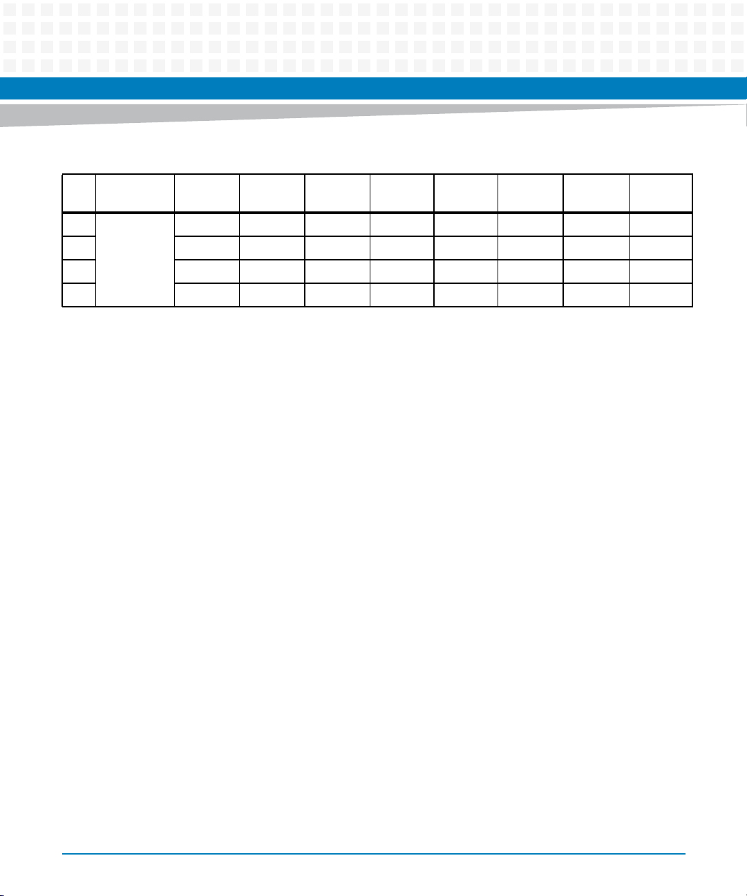
Controls, LEDs and Connectors
Table 3-4 J23/P23 Connector Pin Assignments for ATCA-7350 (continued)
Interface
Pin
Designation A B C D E F G H
7 Unused Reserved Reserved Reserved Reserved Reserved Reserved Reserved Reserved
8 Reserved Reserved Reserved Reserved Reserved Reser ved Reser ved Reserved
9 Reserved Reserved Reserved Reserved Reserved Reser ved Reser ved Reserved
10 Reserved Reserved Reserved Reserved Reserved Reserved Reserved Reserved
All the tx/rx signals are defined from ATCA-7350 side.
3.4.1.3 Zone 3 Connectors
Zone 3 is composed of three connectors, J15, J29, and J31. The three connectors are used to
connect RTMs with ATCA-7350s. Zone 3 defines the following signals:
USB (USB)
VGA
IPMC SMBus
Power (VCC 12VDC, VSBY 5V5)
PCI-E Channels
General control signals (RTM PRESENT, RTM RST, LEDs)
ATCA-7350 works with RTM-ATCA-7150
Fabric Channel Ports Reserved
ATCA-7350 works with RTM-ATCA-7350
Fabric Channel Port 0, Port 1, Port 2, Port 3 (XAUI)
J15 uses a common 2mm HM connector. J29 uses a half-height ZD connector. J31 uses a ZD
connector.
The following table shows the J15 pinout. PinA1 on the server blade side is on the top of the
connector while the server blade is placed top side upwards and the face plate is left.
ATCA-7350 Installation and Use (6806800G59G)
67
Page 68
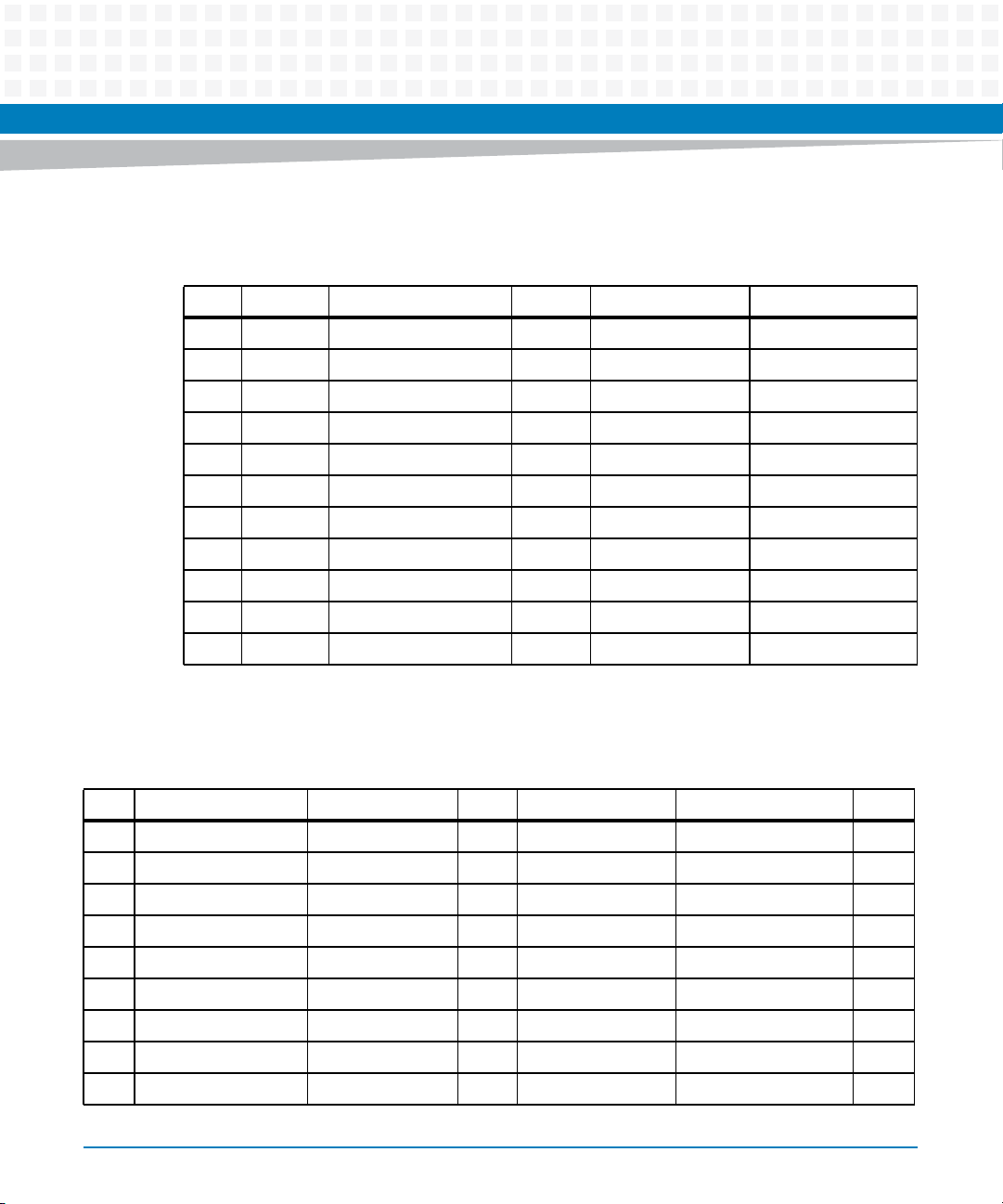
Controls, LEDs and Connectors
RTM_EN0_ and RTM_EN_ are signals that indicate the RTM is firmly inserted.
Table 3-5 J15 Pinout
HM A B C D E
1 VSB5V RTM_EN0 GND RTM_OOSR_ RTM_HEALTHY_G_
2 VSB5V RTM_HOTSPWAP_ GND RTM_HEALTHY_R RTM_OOSY_
3 +12V RTM_TOP_EJECTOR_ GND RTM_SDA RTM_SCL
4 +12V RT;_EPROM_WE GND VGA_RED CPLD_RTM_TDI
5 +12V RTM_BOT_EJECTOR_ GND VGA_BLUE RTM_JTAG_TDO
6 +12V RTM_KBCLK GND VGA_GREEN CPLD_RTM_TCK
7 +12V RTM_MSDAT GND VGA_HS CPLD_RTM_TMS
8 +12V RTM_MSCLK GND VGA_VS CPLD_RTM_TRST
9 +12V RTM_KBDAT GND VGA_DDCCLK RTM_PWR_GOOD
10 +12V RTM_USB_P GND VGA_DDCDAT RTM_LM80_INT_
11 +12V RTM_USB_N GND RTM_SBY_RST RTM_EN_
J29 is used for port1 and port2 signals of the Fabric interface, and the PCIE signals from MCH.
Table 3-6 J29 Pinout
ZD1 A B C D
1 RTM_SYSLED_G_ RESERVED GND RTM_SYSLED_R_ RESERVED GND
2 RTM_FC2_TX2_H RTM_FC2_TX2_L GND RTM_FC1_TX2_H RTM_FC1_TX2_L GND
3 RTM_FC2_RX2_H RTM_FC2_RX2_L GND RTM_FC1_RX2_H RTM_FC1_RX2_L GND
4 RTM_FC2_TX1_H RTM_FC2_TX1_L GND RTM_FC1_TX1_H RTM_FC1_TX1_L GND
5 RTM_FC2_RX1_H RTM_FC2_RX1_L GND RTM_FC1_RX1_H RTM_FC1_RX1_L GND
6 RTM_PE7_PRSNT_R_ RTM_PE7_RST_ GND MCH_EXP7_RXP3 MCH_EXP7_RXN3 GND
7 RTM_EXP7_RXP3 RTM_EXP7_RXN3 GND MCH_EXP7_RXP2 MCH_EXP7_RXN2 GND
8 RTM_EXP7_RXP2 RTM_EXP7_RXN2 GND MCH_EXP7_RXP1 MCH_EXP7_RXN1 GND
9 RTM_EXP7_RXP1 RTM_EXP7_RXN1 GND MCH_EXP7_RXP0 MCH_EXP7_RXN0 GND
68
ATCA-7350 Installation and Use (6806800G59G)
Page 69

Controls, LEDs and Connectors
Table 3-6 J29 Pinout (continued)
ZD1 A B C D
10 RTM_EXP7_RXP0 RTM_EXP7_RXN0 GND RTM_PCIE7_CLK_P RTM_PCIE7_CLK_N GND
Table 3-7 J31 Pinout
ZD2 A B C D E F G H
1 RTM_
PE_SD
A
2 RTM_
EXP6_
RXP1
3 RTM_
EXP6_
RXP0
4 RTM_
EXP5_
RXP1
5 RTM_
EXP5_
RXP0
6 RTM_
EXP4_
RXP1
7 RTM_
EXP4_
RXP0
8 RTM_
PE6_P
RSNT_
R_
RTM_PE
_SCL
RTM_EX
P6_RXN
1
RTM_EX
P6_RXN
0
RTM_EX
P5_RXN
1
RTM_EX
P5_RXN
0
RTM_EX
P4_RXN
1
RTM_EX
P4_RXN
0
RTM_PE
5_PRSN
T_R_
GNDMCH_E
XP6_R
XP1
GNDMCH_E
XP6_R
XP0
GNDRTM_P
CIE6_C
LK_P
GNDMCH_E
XP5_R
XP1
GNDMCH_E
XP5_R
XP0
GNDMCH_E
XP4_R
XP1
GNDMCH_E
XP4_R
XP0
GNDRTM_P
E4_PRS
NT_
MCH_E
XP6_RX
N1
MCH_E
XP6_RX
N0
RTM_P
CIE6_C
LK_N
MCH_E
XP5_RX
N1
MCH_E
XP5_RX
N0
MCH_E
XP4_RX
N1
MCH_E
XP4_RX
N0
RTM_P
E5_WA
KE_
GNDRTM_E
XP6_RX
P3
GNDRTM_E
XP6_RX
P2
GNDRTM_E
XP5_RX
P3
GNDRTM_E
XP5_RX
P2
GNDRTM_P
CIE4_CL
K_P
GNDRTM_E
XP4_RX
P3
GNDRTM_E
XP4_RX
P2
GNDRTM_PE
6_RST_
RTM_
EXP6_
RXN3
RTM_
EXP6_
RXN2
RTM_
EXP5_
RXN3
RTM_
EXP5_
RXN2
RTM_
PCIE4
_CLK_
N
RTM_
EXP4_
RXN3
RTM_
EXP4_
RXN2
RTM_
PE5_R
ST_
GNDMCH_E
XP6_RX
P3
GNDMCH_E
XP6_RX
P2
GNDMCH_E
XP5_RX
P3
GNDMCH_E
XP5_RX
P2
GNDRTM_P
CIE5_C
LK_P
GNDMCH_E
XP4_RX
P3
GNDMCH_E
XP4_RX
P2
GNDRTM_P
E4_RST
_
MCH_E
XP6_RX
N3
MCH_E
XP6_RX
N2
MCH_E
XP5_RX
N3
MCH_E
XP5_RX
N2
RTM_P
CIE5_C
LK_N
MCH_E
XP4_RX
N3
MCH_E
XP4_RX
N2
RTM_P
E4_WA
KE_
GND
GND
GND
GND
GND
GND
GND
GND
9 RTM_
FC2_T
X3_H
ATCA-7350 Installation and Use (6806800G59G)
RTM_FC
2_TX3_
L
GNDRTM_F
C1_TX
3_H
RTM_F
C1_TX3
_L
GNDRTM_F
C2_TX0
_H
RTM_
FC2_T
X0_L
GNDRTM_F
C1_TX0
_H
RTM_F
C1_TX0
_L
GND
69
Page 70

Controls, LEDs and Connectors
Table 3-7 J31 Pinout (continued)
ZD2 A B C D E F G H
10 RTM_
FC2_R
X3_H
RTM_FC
2_RX3_
L
GNDRTM_F
C1_RX
3_H
RTM_F
C1_RX3
_L
GNDRTM_F
C2_RX0
_H
RTM_
FC2_R
X0_L
GNDRTM_F
C1_RX0
_H
3.4.2 Face Plate (ATCA-7350) Connectors
3.4.2.1 SAS HDDs
The ATCA-7350 supports two hot-swappable 2.5-inch SFF SAS/SATA HDD and supports
hardware RAID 0/1.
For details on how to install, remove, and install a hard disk, refer to the ATCA-7X50-HDDxSAS/SATA Installation Information and section RAID Operations and Disk Hot-Swap.
RTM_F
C1_RX0
_L
GND
70
The SAS Controller of the ATCA-7350 supports the Serial Attached SCSI Standard,
Version1.0/Version 1.1. The hardware design of the ATCA-7350 supports the Serial ATA
Specification Version 1.0a and the SATA II.
ATCA-7350 Installation and Use (6806800G59G)
Page 71
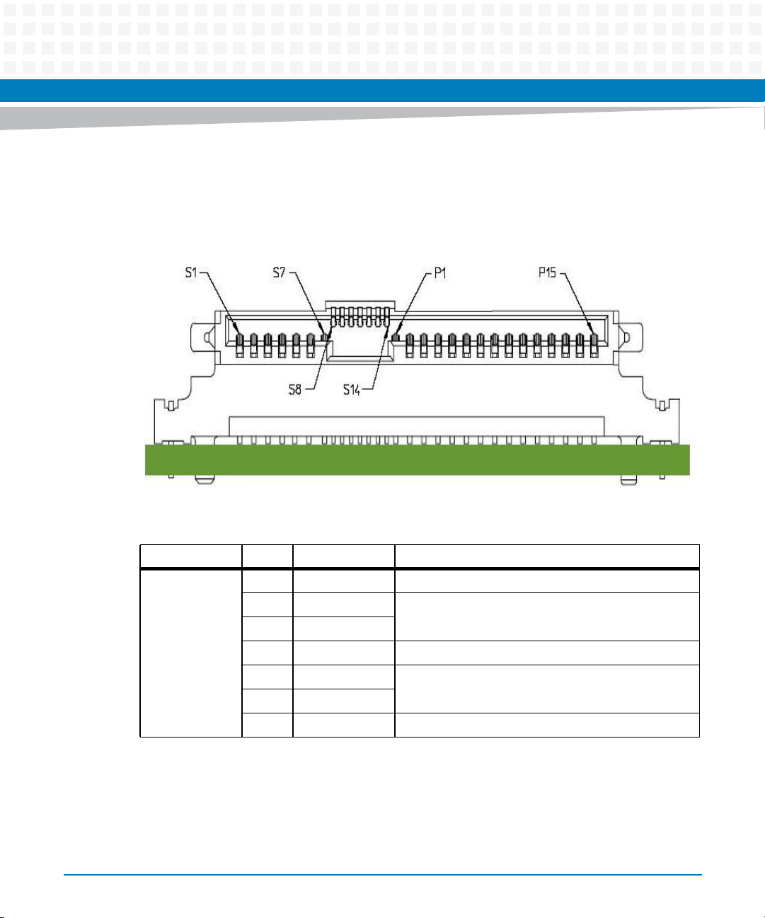
Controls, LEDs and Connectors
The ATCA-7350 utilizes two SAS internal cable receptacle connectors. The connector provides
contact for the power pins and only the primary physical link. The pinout and pin assignment
information are as follow:
Figure 3-5 PINOUT of SAS Connector
Table 3-8 SAS Connector Pin Assignments
Segment PIN Name Description
Primary Signals S1 GROUND Connected to the logic Ground of ATCA-7350
S2 TP+ Primary Transmitting Pair. Driven by SAS controller of
S3 TP-
S4 GROUND Connected to the logic Ground of ATCA-7350
S5 RP- Primary Receiving Pair. Driven by the target device.
S6 RP+
S7 GROUND Connected to the logic Ground of ATCA-7350
ATCA-7350 Installation and Use (6806800G59G)
ATCA-7350.
71
Page 72
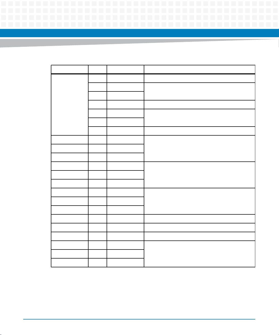
Controls, LEDs and Connectors
Table 3-8 SAS Connector Pin Assignments (continued)
Segment PIN Name Description
Secondary
Signals
S8 GROUND Connected to the logic Ground of ATCA-7350
S9 TS+ Secondary Transmitting Pair. Not connected on ATCA-
S10 TS-
S11 GROUND Connected to the logic Ground of ATCA-7350
S12 RS- Secondary Receiving Pair. Not connected on ATCA-
S13 RS+
S14 GROUND Connected to the logic Ground of ATCA-7350
P1 V33 3.3V Power Supply. Connected to ATCA-7350 3.3V
P2 V33
P3 V33, precharge
P4 GROUND Connected to the logic Ground of ATCA-7350
7350.
7350.
power plane.
72
P5 GROUND
P6 GROUND
P7 V5, precharge 5V Power Supply. Connected to ATCA-7350's 5V
P8 V5
P9 V5
P10 GROUND Connected to the logic Ground of ATCA-7350
P11 READY LED Not used on ATCA-7350, No connection.
P12 GROUND Connected to the logic Ground of ATCA-7350
P13 V12, precharge 12V Power Supply. Connected to ATCA-7350's 12V
P14 V12
P15 V12
power plane through the slow start control circuit.
power plane through the slow start control circuit.
ATCA-7350 Installation and Use (6806800G59G)
Page 73
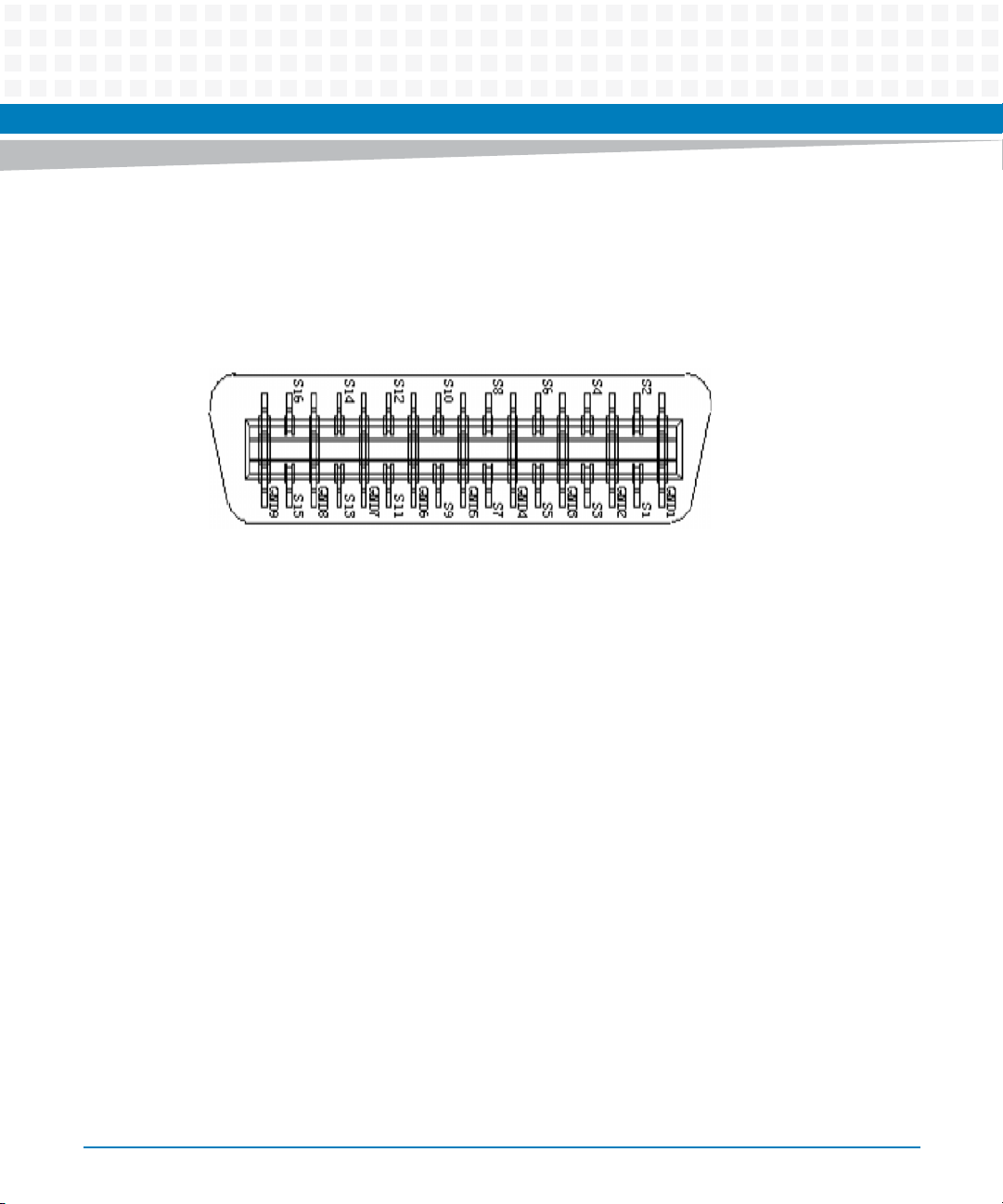
3.4.2.2 SAS Ports
The front panel of ATCA-7350 provides two 3.0 Gbit/s SAS connectors. The pinout and pin
assignment information are as follows:
Figure 3-6 Pinout of SAS Connector
Controls, LEDs and Connectors
ATCA-7350 Installation and Use (6806800G59G)
73
Page 74
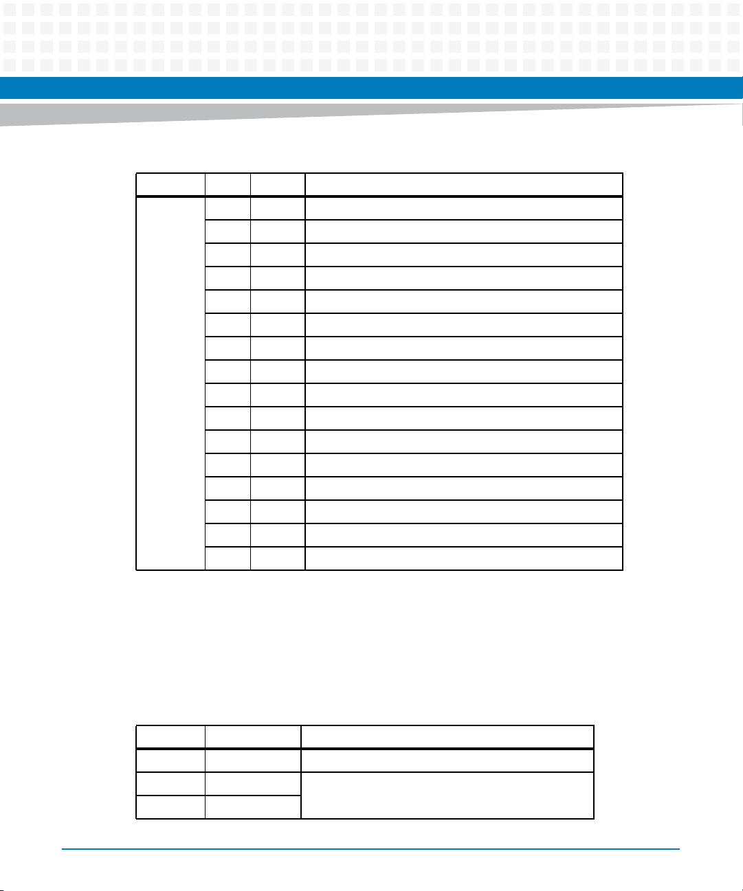
Controls, LEDs and Connectors
Table 3-9 SAS Connector Pin Assignments
Segment PIN Name Description
Signals S1 RX2+ Receive Positive differential data of sas1064 port 2
S2 RX2- Receive Negative differential data of sas1064 port 2
S3 RX3+ Receive Positive differential data of sas1064 port 3
S4 RX3- Receive Negative differential data of sas1064 port 3
S5 NC NO CONNECT
S6 NC NO CONNECT
S7 NC NO CONNECT
S8 NC NO CONNECT
S9 NC NO CONNECT
S10 NC NO CONNECT
S11 NC NO CONNECT
3.4.2.3 USB Ports
ATCA-7350 has a dual port USB Connector on the face plate. USB ports on the front port are
compliant to the USB 2.0 Specification and can run at High speed mode. See the USB Port Pin
Assignment table for the pinout information.
Table 3-10 USB Connector Pin Assignments
Pin Pin Name Description
1 +5V +5V Power Supply, Max 500mA each port.
2 Data- Differential Data transmitting pair.
3Data+
74
S12 NC NO CONNECT
S13 TX3- Transmit Negative differential data of sas1064 port 3
S14 TX3+ Transmit Positive differential data of sas1064 port 3
S15 TX2- Transmit Negative differential data of sas1064 port 2
S16 TX2+ Transmit Positive differential data of sas1064 port 2
ATCA-7350 Installation and Use (6806800G59G)
Page 75
Table 3-10 USB Connector Pin Assignments (continued)
Pin Pin Name Description
4 GROUND Ground, connected to the logic GND of ATCA-7350.
3.4.2.4 Serial Port
ATCA-7350 provides a signal serial port using a RJ-45 style shielded connector. The serial port
can be switched to system (host processor) serial port or IPMC control console serial port via
IPMI command. See ATCA-7350: Control via IPMI Programmer’s Reference for details.
Table 3-11 Serial Port Connector Pin Assignments
Pin Pin Name Description
1 NC. Not connected.
2 NC. Not connected.
Controls, LEDs and Connectors
3 TXD Data transmitting signal.
4 GROUND Ground, connected to the logic GND of ATCA-7350.
5 GROUND Ground, connected to the logic GND of ATCA-7350.
6 RXD Data receiving signal.
7 NC. Not connected.
8 NC. Not connected.
Pay Attention to Important Information
By default the payload console is selected (9600 baud). However as long as the payload is not
powered, the IPMC console is visible (115200 baud) always. With powering the payload the
IPMC automatically selects the payload serial console if the serial port selection is not
modified.
The serial port selection can be modified by executing the OEM IPMI command "Set Serial
Output" In case of the IPMC is selected with such command, the IPMC serial console is
selected also when the payload is powered.
Be aware that this selection is persistent.
ATCA-7350 Installation and Use (6806800G59G)
75
Page 76
Controls, LEDs and Connectors
3.4.3 Onboard Jumpers
All the jumpers are only for debugging and manufacturing only. They should not be changed
by the customers.
3.5 LEDs
The ATCA-7350 face plate provides the following LEDs:
Out of service (OOS) LED
In Service (IS) LED
76
Attention (ATN) LED
H/S LED
HD LED
You can monitor the LEDs to diagnose the current status of the ATCA-7350.
Table 3-12 lists the LEDs on the ATCA-7350 face plate.
Table 3-12 LEDs on the ATCA-7350 Face Plate
LED Color Meaning Description
Out Of
Service
(OOS)
In Service
(IS)
Red or amber Service status LED The OOS LED is set to on (red) when the
payload processor starts running.
Payload Management software is responsible
for controlling the OOS LED.
Red, green or
amber
Health LED The IS LED is off when the payload processor
starts running.
Payload Management software is responsible
for controlling the IS LED.
ATCA-7350 Installation and Use (6806800G59G)
Page 77

Controls, LEDs and Connectors
Table 3-12 LEDs on the ATCA-7350 Face Plate (continued)
LED Color Meaning Description
Attention
(ATN)
HOTSWAP Blue Hot swap LED Off: The ATCA-7350 is in activated state.
Amber User LED The ATN LED is set to off when the payload
processor starts running.
Payload Management software is responsible
for controlling the ATN LED.
On: The ATCA-7350 is inserted, but in
deactivated state or not powered on.
1
Blinking at the long blink rate
: The
ATCA-7350 is requesting for activation.
2
Blinking at the short blink rate
: The
ATCA-7350 is requesting for
deactivation.
HD Green Hard disk running
LED
Blinking: The hard disk reads or writes
data.
Off: The HD LED is off in other situations.
1. Blinking at the long blink rate means that the LED is on for 900 ms and then off for 100 ms alternatively
2. Blinking at the short blink rate means that the LED is on for 100 ms and then off for 900 ms alternatively.
ATCA-7350 Installation and Use (6806800G59G)
77
Page 78

Controls, LEDs and Connectors
78
ATCA-7350 Installation and Use (6806800G59G)
Page 79

Functional Description
4.1 Overview
The ATCA-7350 is designed for High Availability, Switched Network Computing. Bulk storage
for the system is connected through optional dual Fiber Channel (FC) or via external SAS
connection.
The specifications and functions of the ATCA-7350 are listed below.
4.1.1 Processor
One or two Intel® Quad-Core LV Xeon™ 5408 (2.13 GHz) with 12MB L2 cache per processor
4.1.2 Chipset
Intel® 5000P/6321 ESB
Chapter 4
1066MHz FSB
4.1.3 Memory
Up to 32 GB FB-DIMM DDR2-533/667 via four DIMM sockets
4.1.4 I/O Features (with RTM-ATCA-7350)
Dual 10/100/1000 Mbps Ethernet (Base interface, with PXE function supporting)
Dual 1000 Mbps Ethernet (Fabric interface)
One 1000 Mbps Ethernet (Update channel interface)
E-keying on Fabric channel and Update channel
PICMG 3.1 Option 9 Fabric Interface Support
Two RTM IO module slots for GE daughter cards or FC daughter card
4.1.5 I/O Features (with RTM-ATCA-7150)
Dual 10/100/1000 Mbps Ethernet (Base interface, with PXE function supporting)
Dual 1000 Mbps Ethernet (Fabric interface)
ATCA-7350 Installation and Use (6806800G59G)
79
Page 80

Functional Description
One 1000 Mbps Ethernet (Update channel interface)
E-keying on Fabric channel and Update channel
Four RTM IO module slots for GE daughter cards or FC daughter cards
4.1.6 Front Panel
2 x USB2.0
One serial port (RJ-45)
Two SAS ports (SAS 4x receptacle connector)
One reset button
4.1.7 Onboard Storage
Two onboard hot-swappable 2.5-inch SFF SAS/SATA HDDs, Supporting hardware RAID 0/1
On-board USB flash chips, 1GB capacity
4.1.8 Management
IPMC, dual firmware image, Dual IPMBs
SOL
4.1.9 Form Factor
8 U x 280 mm x 1.2 inch pitch
Single slot
4.1.10 Power
Type: 150 W
Max: 200 W
80
ATCA-7350 Installation and Use (6806800G59G)
Page 81

4.1.11 Environment
Long term ambient temperature: 5ºC to +40ºC
Short term ambient temperature: -5ºC to +55ºC
Long term ambient humidity: 5%RH to 85%RH
Short term ambient humidity: 5%RH to 90%RH
4.1.12 Target Certifications
UL / CSA, CB, TUV-Mark
4.1.13 Design Standard
PICMG 3.0 R2.0
IPMI 2.0
Functional Description
ATCA-7350 Installation and Use (6806800G59G)
81
Page 82
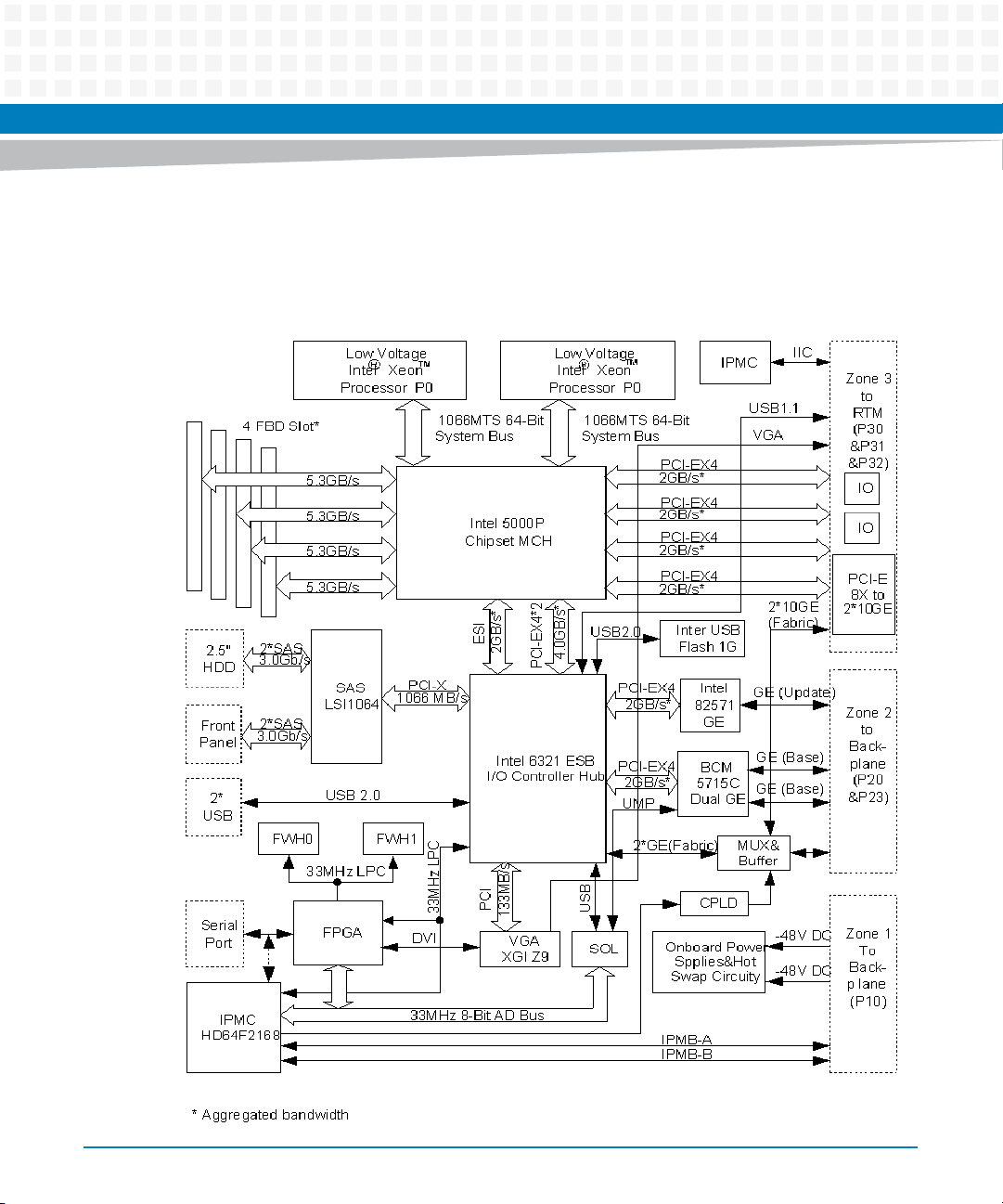
Functional Description
4.2 Block Diagram
Figure 4-1 Block Diagram of ATCA-7350
82
ATCA-7350 Installation and Use (6806800G59G)
Page 83

4.3 Processors
The ATCA-7350 supports two Low Voltage Intel® Quad-Core LV Xeon™ 5408 processors. Each
processor runs at 2.13 GHz clock frequency and features a 12MB L2 cache.
The processors with quad cores each provide exceptional performance for applications running
on advanced operating systems such as Windows, Linux and UNIX.
The Quad-Core Intel® Xeon® processors are 64-bit server processors utilizing four Intel Core™
micro architecture cores. They support Intel® 64 architecture as an enhancement to Intel's IA32 architecture. This enhancement allows the two processors to execute operating systems
and applications written to take advantage of the 64-bit extension technology.
4.3.1 Features
The processors provide the following features.
Functional Description
Quad-Core processing with Intel® Core™ microarchitecture
Performance optimized version available
32-KB Level 1 instruction and 32-KB Level 1 data cache per core
12MB L2 Cache
Intel® Advanced Smart Cache
1066MHz system bus with Dual Independent Bus architecture
Intel® Extended Memory 64 Technology (Intel® EM64T)
Intel® Wide Dynamic Execution
Intel® Advanced Digital Media Boost
Intel® Smart Memory Access
Thermal Monitor 1 (TM1)
Thermal Monitor 2 (TM2)
Platform Environment Control Interface (PECI) to monitor Digital Thermal Sensors
ATCA-7350 Installation and Use (6806800G59G)
83
Page 84
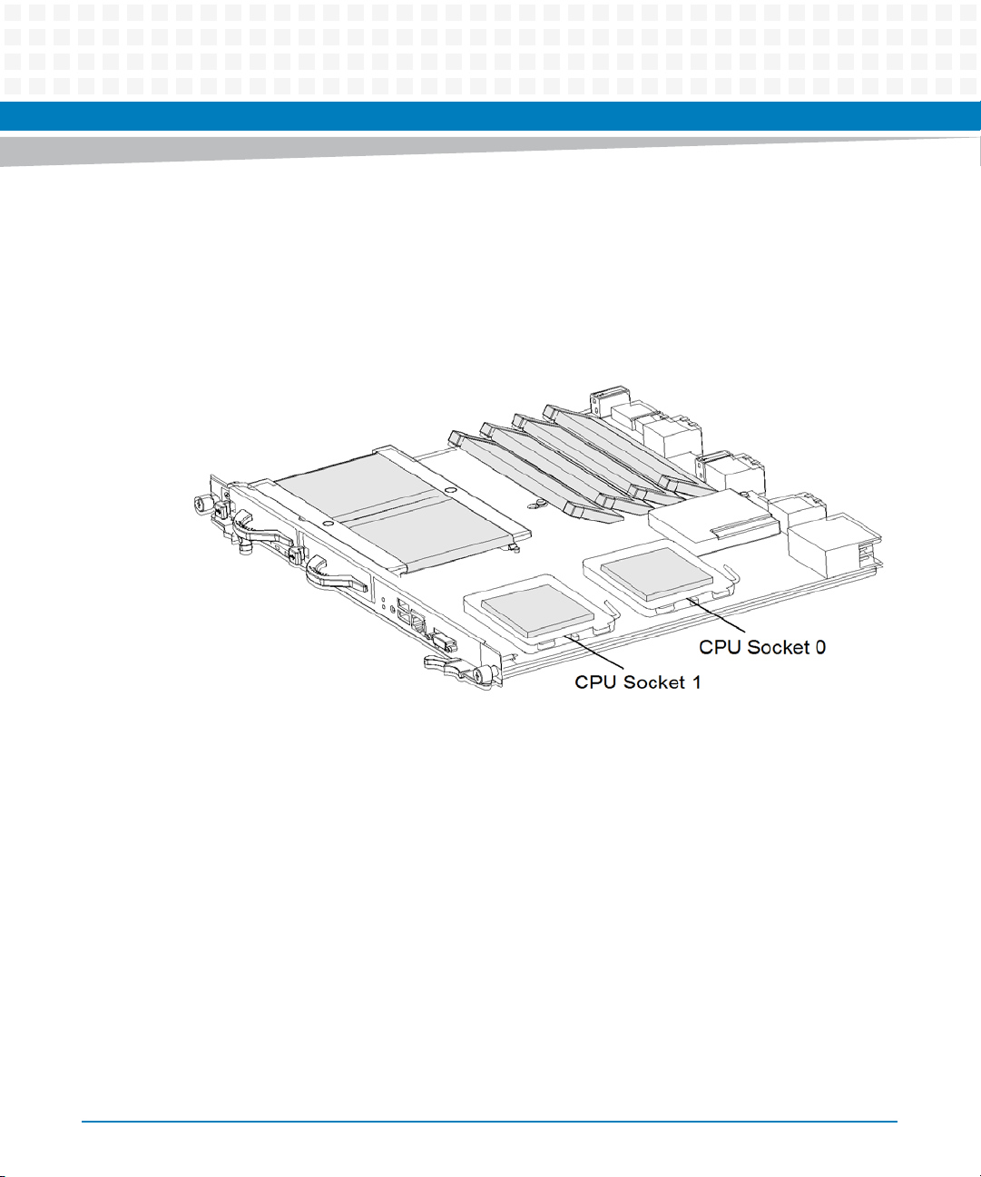
Functional Description
4.3.2 Processor Locations
The ATCA-7350 can be configured with two central processing units (CPUs) or a single CPU.
When only one CPU is configured, the CPU must be installed in CPU socket 0. The positions of
CPU socket 0 and CPU socket 1 are shown inFigure 4-2.
Figure 4-2 Processor Locations
4.4 Chipset
4.4.1 Memory Controller Hub
The Memory Controller Hub connects the processors to the main memory and the payload I/O
of the ATCA-7350. It features:
Quad-pumped 1066 MHz FSB
Point to point DIB processor system bus interface
Peak address generation rate of 533 Million Addresses/second
84
ATCA-7350 Installation and Use (6806800G59G)
Page 85

64-bit data buses with peak bandwidths of 8.5 GB/s (1066MT/s)
36-bit host addressing, decoding up to 64 GB of the processor's memory address space
Four channels of Fully Buffered DIMM (FB-DIMM) memory
4.25 GB/s read bandwidth each FB-DIMM channel for DDR2 533 FB-DIMM memory and
5.3GB/s for DDR2 667FB-DIMM memory
8.5 GB/s write memory bandwidth for four FB-DIMM channels and 10.7 GB/s for DDR2
667FB-DIMM memory
6 x4 standard PCI Express ports and an additional x4 ESI port for Intel® 631xESB/632xESB
I/O Controller Hub
ESI chip-to-chip connection to the Intel 6321ESB I/O Controller Hub
4.4.2 Enterprise South Bridge
The Intel® 631xESB/632xESB I/O Controller Hub provides extensive I/O support.
Functional Description
Functions and capabilities include:
Enterprise South Bridge Interface (ESI) and PCI Express X8 upstream ports to Memory
Controller Hub (MCH)
PCI Express Specification, Revision 1.0a-compliant
PCI Protocol Addendum and PCI Electrical and Mechanical Addendum to the PCI Local Bus
Specification, Revision 2.0a-compliant
PCI Local Bus Specification, Revision 2.3-compliant with support for 33 MHz PCI operations
(supports up to seven Req/Gnt pairs)
ACPI power management logic support
Enhanced DMA controller, interrupt controller, and timer functions
USB host interface supporting UHCI and EHCI 2.0 host controller
PICMG-compliant Serdes backplane Gigabit Ethernet support
System Management Bus (SMBus) Specification, Version 2.0-compliant with additional
support for I2C devices
ATCA-7350 Installation and Use (6806800G59G)
85
Page 86

Functional Description
Low Pin Count (LPC) interface
Firmware Hub (FWH) interface support
4.5 Memory
The ATCA-7350 supports four DDR2 533/677 Fully Buffered DIMMs (FBD).
The ATCA-7350 memory controller hub complies with the FB-DIMM specification definition of
a host.
The ATCA-7350 has four FBD slots (J25, J39, J27, and J28) for up to four FBDs. Slots J25, J39, J27,
and J28 correspond to Channel 0, Channel 1, Channel 2, and Channel 3 of the memory
controller hub (MCH) respectively.
The FBD channels of the MCH reside on two branches. FBD Channel 0 and Channel 1 reside on
branch 0, while FBD Channel 2 and Channel 3 reside on branch 1.
The ATCA-7350 can be configured with one, two, or four DIMMs. The positions for installing
the DIMMs are shown in Table 2-6. Figure 2-3 shows the DIMM slots positions.
Limited by the physical dimensions of the blade, FBDs installed on ATCA-7350 must not be
higher than 30.5mm and must not be thicker than 6.6mm.
FB-DIMMs with quad rank architecture are not supported by the memory controller and can
not be installed on the ATCA-7350.
4.6 I/O
4.6.1 Keyboard and Mouse
The ATCA-7350 supports USB keyboard and mouse and also PS2 keyboard and mouse via a
converter cable. The USB port connector for the keyboard and mouse is on the front panel of
the RTM.
86
ATCA-7350 Installation and Use (6806800G59G)
Page 87

4.6.2 Serial Port
The ATCA-7350 uses a FPGA to implement system (host processor) serial port controller.
The serial port on the front panel of ATCA-7350 can be switched to system (host processor)
serial port or IPMC console serial port by IPMI command (see command "Set Serial Output" in
the ATCA-7350: Control via IPMI Programmer’s Reference).
The system serial port is selected by default, and can be switched to IPMC serial port by IPMI
command.
The serial port parameter can be set via BIOS SETUP UTILITY, proceed as follows:
1. To set the Serial Port Mode
The Bits per second can be set to 115200, 57600, 38400, 19200 and 09600. The default
baud rate setting of the system serial port is 09600bps, also set Data bits to 8, Parity to
None, Stop bits to 1.
2. Set Flow Control to None
Functional Description
3. Set Terminal Type to ANSI
Flow Control must be set to None and Terminal Type must be set to ANSI in BIOS Setup
Utility.
The default baud rate setting of the IPMC serial port is 115200bps, if the serial port on
the front panel of ATCA-7350 is switched to IPMC serial port, pay attention to the baud
rate.
4.6.3 Real-Time Clock
The Real Time Clock (RTC) of the ATCA-7350 is generated by the circuit powered by the battery
in the ESB. The clock source is a 32.768 KHz crystal resonator. If there is no battery, the RTC is
powered by the SMM through the IPMB.
The parameters of the crystal resonator are as follows:
Frequency tolerance @ 25 ºC: ±20ppm
Frequency stability: maximum of -0.04ppm/_ ºC)2
Aging (1st year @ 25 ºC): ±3ppm
ATCA-7350 Installation and Use (6806800G59G)
87
Page 88

Functional Description
4.6.4 Gigabit Ethernet (ATCA-7350 with RTM-ATCA-7350)
The ATCA-7350 with RTM-ATCA-7350 provide the following 1/10 Gigabit Ethernet (GE)
interfaces:
Two Base interface GE (10/100/1000 BASE-T) on ATCA-7350.
The two GE Base interfaces support PXE function. PXE function can be enabled or disabled
through the BIOS SETUP UTILITY (Disabled by default), more details see section 6.3.8 PXE
Function Configuration Submenu, The MAC address needed during the PXE network
booting process are shown in this BIOS menu.
Two Fabric interface 10GE on ATCA-7350 (requires RTM-ATCA-7350 to be installed).
One Update Channel interface GE (1000Base-SX/LX) on ATCA-7350.
Two customized 4 Lane PCI-E buses in RTM-ATCA-7350, providing 2, 4 external GE ports
with 1, 2 external GE daughter cards configured.
Please refer to RTM-ATCA-7350 Installation and Use manual.
4.6.5 Gigabit Ethernet (ATCA-7350 with RTM-ATCA-7150)
The ATCA-7350 with RTM-ATCA-7150 provide the following Gigabit Ethernet (GE) interfaces:
Two Base interface GE (10/100/1000 BASE-T) on ATCA-7350.
The two GE Base interfaces support PXE function. PXE function can be enabled or disabled
through the BIOS SETUP UTILITY (Disabled by default), more details see section 6.3.8 PXE
Function Configuration Submenu, The MAC address needed during the PXE network
booting process are shown in this BIOS menu.
Two Fabric interface 1 GE on ATCA-7350.
One Update Channel interface GE (1000Base-SX/LX) on ATCA-7350.
Four customized 4 Lane PCI-E buses in RTM-ATCA-7150, providing 2, 4, 6, 8 external GE
ports with 1, 2, 3, 4 external GE daughter card configured.
Please refer to RTM-ATCA-7150 Installation and Use manual.
88
ATCA-7350 Installation and Use (6806800G59G)
Page 89

Functional Description
4.6.6 Fiber Channel (ATCA-7350 with RTM-ATCA-7350)
The ATCA-7350 with RTM-ATCA-7350 can provide two external Fiber channel ports through
the RTM, with one external FC daughter card configured (installed on connectors J1 of RTMATCA-7350).
Please refer to RTM-ATCA-7350 Installation and Use manual.
4.6.7 Fiber Channel (ATCA-7350 with RTM-ATCA-7150)
The ATCA-7350 with RTM-ATCA-7150 can provide two or four external Fiber channel ports
through the RTM, with one or two external FC daughter cards configured (installed on
connectors J2, J4 of RTM-ATCA-7150).
Please refer to RTM-ATCA-7150 Installation and Use manual.
4.6.8 SAS HDD
The ATCA-7350 supports two hot-swappable RAID1 2.5 inch SAS/SATA HDD. The SAS
controller is SAS1064 chip of LSI for providing 3.0 G SAS interfaces.
4.6.9 SAS Port
The panel of the ATCA-7350 provides two external SAS port (3.0 Gbit/s) for connecting to
JBOD.
Provides two fully independent phys.
Support 3.0 Gbit/s and 1.5 Gbit/s SAS data transfers for each phy.
Support SSP to enable communication with other SAS devices.
Support SMP to communicate topology management information.
Provides a serial, point-to-point, enterprise-level storage interface.
Simplifies cabling interface that supports up to 128 devices through multiple expanders (if
available in external storage array).
Supports wide ports consisting of two phys.
Transfers data using SCSI information units.
ATCA-7350 Installation and Use (6806800G59G)
89
Page 90

Functional Description
4.6.10 USB Port
The ATCA-7350 provides three external USB interfaces. The two USB interface on the ATCA7350 panel complies with USB2.0 and can work in the High Speed mode. The other one on the
panel of the RTM complies with USB1.1 and can be used to connect such devices as mouse and
keyboard.
4.7 BIOS BOOT Banks
The ATCA-7350 supports two 8 Mbit (1 MByte) BIOS flash ROMs, i.e. BIOS bank A and BIOS
bank B. The blade supports redundant BIOS mechanism and the IPMC controls active and
standby modes to improve system reliability.
The ATCA-7350 boots up from BIOS bank A i.e. flash ROM by default.
4.7.1 Redundant BIOS
The ATCA-7350 supports the dual-BIOS backup function. If the current BIOS fails to boot, the
current BIOS is switched over to the backup BIOS automatically.
When you upgrade the BIOS through the IPMC or with an Artesyn upgrade tool, you can
upgrade the currently selected BIOS bank only. To switch over the BIOS and query the current
BIOS, run the commands "Set/Get System Boot Options" together with the OEM boot
parameter #96 mentioned in ATCA-7350 IPMI Users manual.
4.8 Intelligent Platform Management Controller
4.8.1 Functions
The Intelligent Platform Management Controller (IPMC) is based on a High-speed central
processing unit with an internal 16-bit architecture.
The IPMC module provides the following functions:
IPMI 2.0 compatible
PICMG 3.0 R2.0 compatible
90
ATCA-7350 Installation and Use (6806800G59G)
Page 91

Functional Description
65000 SEL entries
Two managed FRU (including RTM) and five unmanaged FRU at best
SDR support
KCS interface support
HPM.1 support
Serial over LAN
Dual image support
Dual handle switch support
Online firmware upgrade
Provides two redundant IPMB (I2C) bus connection to backplane (Zone1).
4.9 Reset Methods
The ATCA-7350 supports the following reset methods:
System software reset
System reset signals asserted by the IPMC software
Reset through the front panel reset button
ATCA-7350 Installation and Use (6806800G59G)
91
Page 92
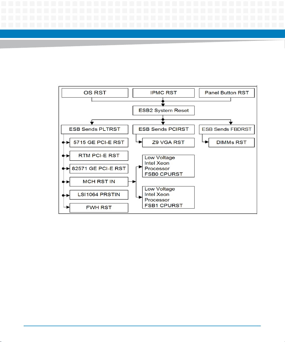
Functional Description
Figure 4-3 shows the detailed ATCA-7350 reset information.
Figure 4-3 Reset Diagram
4.10 WDTs
The ATCA-7350 provides two watchdog timers (WDTs) for the host processor and IPMC of the
system.
92
ATCA-7350 Installation and Use (6806800G59G)
Page 93
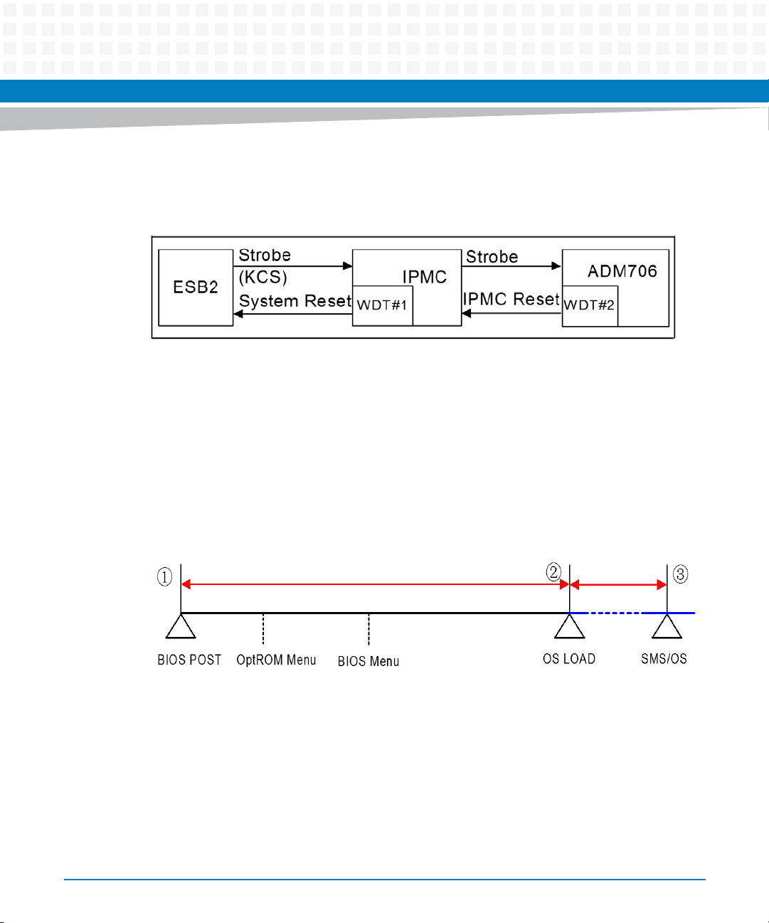
Figure 4-4 shows the relationship between the two WDTs.
Figure 4-4 Relationship between the two WDTs
4.10.1 WDT#1
System software and host BIOS communicate with the IPMC through the keyboard controller
style (KCS) interface. The host processor sends a "Reset WDT message" to the IPMC through the
KCS interface. The timeout threshold of WDT#1 varies with system running status. Here, in the
below figure SMS means System Management Software.
Functional Description
Figure 4-5 WDT operating status
The WDT#1 takes different actions in different phases, see as follows:
1. Before BIOS POST: Before moment as shown in Figure 4-5, the host processor does not
run. The IPMC software records the time period from system reset completion to the
arrival time of the first "Reset WDT message". If the "Reset WDT message" does not arrive
within 40 s, the WDT times out. In this case, the IPMC sends a system reset message.
2. BIOS POST phase: the time period from to as shown in Figure 4-5. In the BIOS POST
phase, the "Reset WDT message" is sent by the BIOS software of the host processor.
ATCA-7350 Installation and Use (6806800G59G)
93
Page 94

Functional Description
Note: Here, BMC means IPMC.
BMC WDT Action For POST in the Advanced setting pane in the BIOS SETUP UTILITY
interface is used to enable/disable WDT in the BIOS POST phase and perform the action
after the WDT times out. BMC WDT for POST phase is enabled by default setting. BMC WDT
Time Out For POST is used to set the timeout threshold of the WDT in the BIOS POST
phase. This threshold can be set to 2, 3, 5, 8, or 15 minutes. This threshold has a default
value of 8 minutes.
3. OS LOAD phase: the time period from to and after , as shown in Figure 4-5. In the
OS LOAD phase, the "Reset WDT message" is sent by the software running in the OS of the
host processor. BMC WDT Action For OS Loader in the Advanced setting pane the BIOS
SETUP UTILITY interface is used to enable/disable WDT in the OS LOAD phase and perform
the action after the WDT times out. BMC WDT for OS LOAD phase is disabled by default
setting. BMC WDT Time Out For OS Loader is used to set the timeout threshold of the WDT
in the OS LOAD phase. This threshold can be set to 2, 3, 5, 8, or 15 minutes.
4.10.2 WDT#2
The IPMC WDT (implemented in hardware) must be strobed by the IPMC firmware. If IPMC
WDT expires, it isolates the blade from the backplane IPMB buses and resets the IPMC.
The watchdog timer is set to trigger the reset of IPMC if the WDT has not be cleared for 1.6
seconds and the IPMC strobes it once 100 milliseconds.
4.11 Power Supplies
The shelf provides blades with two redundant -48 V power inputs through the Zone1
connector; If one power input is faulty, the blades can work normally. This improves system
reliability.
The IPMC monitors whether the two -48 V power inputs are present. At the same time, the
IPMC monitors the two shortest pins on the Zone1 connector to check that if the blade is
properly inserted.
The -48 V DC power inputs supplied through the Zone1 connector are converted to the +12 V
DC voltage. Then the +12 V DC voltage can be converted to the voltages required by each
device on the ATCA-7350.
94
ATCA-7350 Installation and Use (6806800G59G)
Page 95
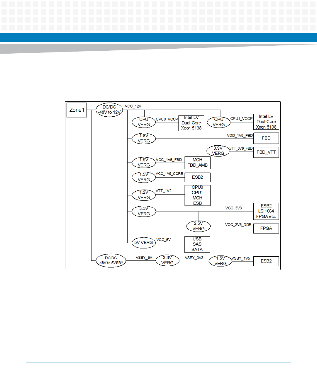
Functional Description
The power supplies of such modules as the IPMC are independent and generated through the
-48 V DC to +5 V DC converter. The IPMC controls power-on and power-off of the ATCA-7350.
Figure 4-6 Power supply topology
ATCA-7350 Installation and Use (6806800G59G)
95
Page 96

Functional Description
4.12 ACPI
Table 1-9 lists the power supply states supported by the ATCA-7350 and the power supply
states of key devices. The ATCA-7350 supports three sleeping states defined in ACPI, S0, S4,
and S5.
Table 4-1 Power states and targeted system power
Global States Sleeping States Processor States Device States
G0 - working state S0 - working C0 - working D0 - working state
G1 - sleeping
state
G2/S5 S5 - Soft off.
G3 -mechanical off DC
power is disconnected
from the chassis.
S4 - Suspend to disk.
Context saved to disk
Context not saved.
Cold boot is required.
No power to the system. No power D3 - no power for
4.13 On-Board USB Flash
The 1 GB USB flash memory is designed on the ATCA-7350, which is used to store OS programs
or applications.
4.14 SOL Daughter Card
SOL daughter card provides the function of transmitting serial port data based on IPMI over
LAN. The IPMC of the ATCA-7350 redirects the OS serial port data to the network through the
RMCP+ protocol. You can access the system serial port of the ATCA-7350 safely.
No power D3 - no power except
for wake up logic.
No power D3 - no power except
for wake up logic.
wake up logic, except
when provided by
battery
or external source.
96
ATCA-7350 Installation and Use (6806800G59G)
Page 97
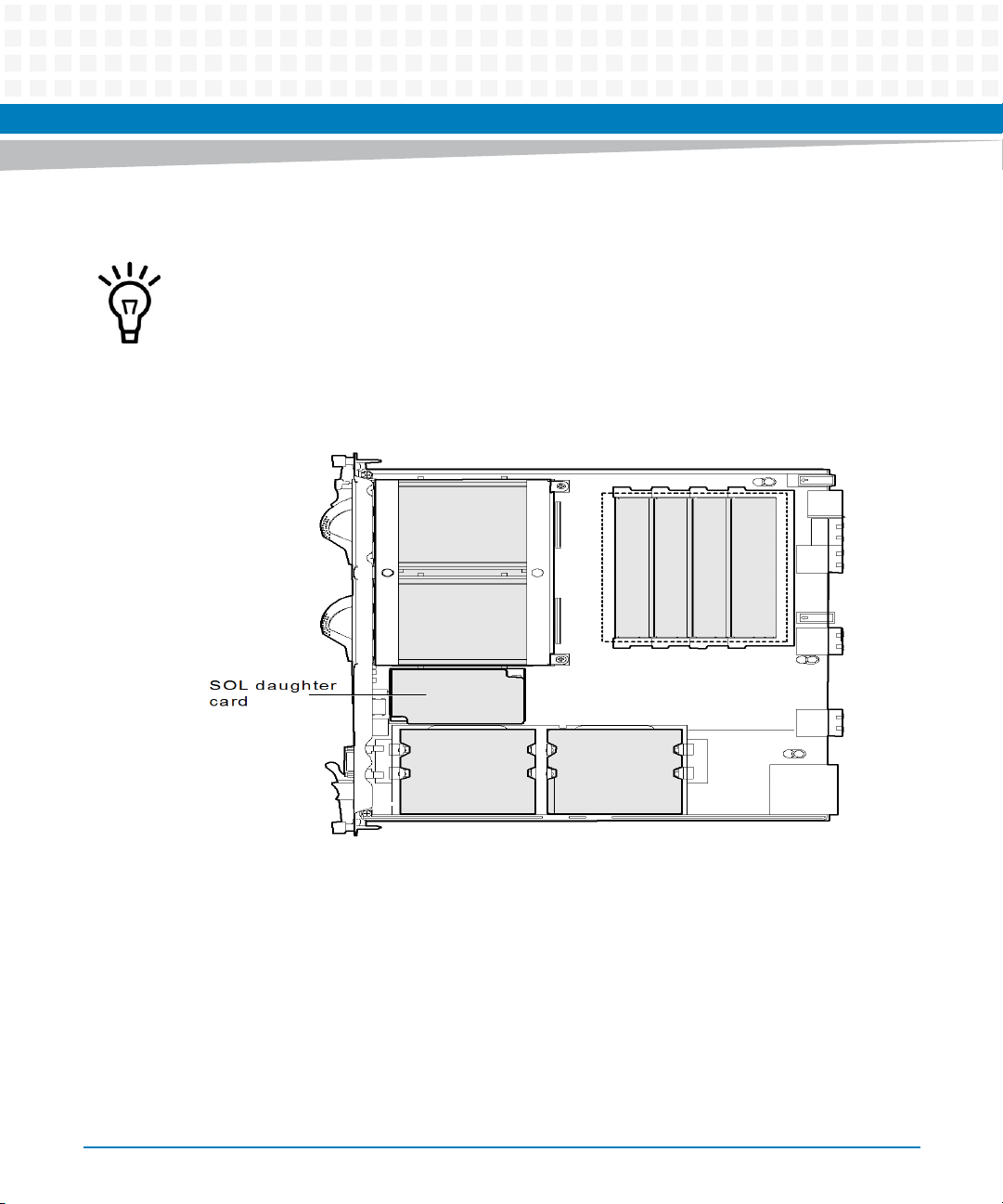
Functional Description
To set and use SOL, refer to Setting Up a Serial Over LAN Session on page 104.
The serial port redirected by the SOL function is the system serial port of the ATCA-7350.
Figure 4-7 SOL Daughter Card Location (J41)
ATCA-7350 Installation and Use (6806800G59G)
97
Page 98

Functional Description
98
ATCA-7350 Installation and Use (6806800G59G)
Page 99

System Management
5.1 Overview
This chapter describes the feature set of the IPMI v.2.0 compliant Intelligent Platform
Management Interface Controller firmware. Furthermore Sensors implemented are described.
For more details about the IPMC and its command set, please see the ATCA-7350 IPMI Users
manual.
5.2 Sensor Information
The ATCA-7350 provides different sensors to monitor various board voltages, temperatures,
board states and events. The sensors available on the blade/RTM are shown in the table below:
Table 5-1 Sensors Overview
Chapter 5
Sensor Name Sensor Type
CPU Inlet Temp Temperature
FBD Inlet Temp Temperature
HD Env Temp Temperature
CPU0 Core Rem Temperature
CPU1 Core Rem Temperature
+3.3V_BAT Voltage
+3.3VCC Voltage
+5VSB Voltage
+12VCC Voltage
+5VCC Voltage
+3.3VSB Voltage
FRU Hot Swap Hot Swap State
IPMB Link State IPMB Link State
-48V Power1 -48V Power1 State
-48V Power2 -48V Power2 State
CPU0 Status CPU0 Status
CPU1 Status CPU1 Status
ATCA-7350 Installation and Use (6806800G59G)
99
Page 100

System Management
Table 5-1 Sensors Overview (continued)
Sensor Name Sensor Type
Watchdog Watchdog State
FW Progress Firmware Progress State
BIOS Bank BIOS Bank State
Log Disabled Is the SEL(System Event Log)
ACPI State ACPI State
For a detailed description please refer to ATCA-7350: Control via IPMI Programmer’s Reference.
disabled
100
ATCA-7350 Installation and Use (6806800G59G)
 Loading...