

Page 1

VXS1-RTM1
Installation and Use
P/N: 6806800P46C
April 2015
Page 2

©
Copyright 2015 Artesyn Embedded Technologies, Inc.
All rights reserved.
Trademarks
Artesyn Embedded Technologies, Artesyn and the Artesyn Embedded Technologies logo are trademarks and service marks of
Artesyn Embedded Technologies, Inc.© 2015 Artesyn Embedded Technologies, Inc. All other product or service names are the
property of their respective owners.
Intel® is a trademark or registered trademark of Intel Corporation or its subsidiaries in the United States and other countries.
Java™ and all other Java-based marks are trademarks or registered trademarks of Oracle America, Inc. in the U.S. and other countries.
Microsoft®, Windows® and Windows Me® are registered trademarks of Microsoft Corporation; and Windows XP™ is a trademark of
Microsoft Corporation.
PICMG®, CompactPCI®, AdvancedTCA™ and the PICMG, CompactPCI and AdvancedTCA logos are registered trademarks of the PCI
Industrial Computer Manufacturers Group.
UNIX® is a registered trademark of The Open Group in the United States and other countries.
Notice
While reasonable efforts have been made to assure the accuracy of this document, Artesyn assumes no liability resulting from any
omissions in this document, or from the use of the information obtained therein. Artesyn reserves the right to revise this document
and to make changes from time to time in the content hereof without obligation of Artesyn to notify any person of such revision or
changes.
Electronic versions of this material may be read online, downloaded for personal use, or referenced in another document as a URL to
an Artesyn website. The text itself may not be published commercially in print or electronic form, edited, translated, or otherwise
altered without the permission of Artesyn.
It is possible that this publication may contain reference to or information about Artesyn products (machines and programs),
programming, or services that are not available in your country. Such references or information must not be construed to mean that
Artesyn intends to announce such Artesyn products, programming, or services in your country.
Limited and Restricted Rights Legend
If the documentation contained herein is supplied, directly or indirectly, to the U.S. Government, the following notice shall apply
unless otherwise agreed to in writing by Artesyn.
Use, duplication, or disclosure by the Government is subject to restrictions as set forth in subparagraph (b)(3) of the Rights in
Technical Data clause at DFARS 252.227-7013 (Nov. 1995) and of the Rights in Noncommercial Computer Software and
Documentation clause at DFARS 252.227-7014 (Jun. 1995).
Contact Address
Artesyn Embedded Technologies Artesyn Embedded Technologies
Marketing Communications Lilienthalstr. 17-19
2900 S. Diablo Way, Suite 190 85579 Neubiberg/Munich
Tempe, Arizona 85282 Germany
Page 3

Contents
Contents
About this Manual . . . . . . . . . . . . . . . . . . . . . . . . . . . . . . . . . . . . . . . . . . . . . . . . . . . . . . . . . . . . . . . . . . . . . . . . 9
Safety Notes . . . . . . . . . . . . . . . . . . . . . . . . . . . . . . . . . . . . . . . . . . . . . . . . . . . . . . . . . . . . . . . . . . . . . . . . . . . . . 15
Sicherheitshinweise . . . . . . . . . . . . . . . . . . . . . . . . . . . . . . . . . . . . . . . . . . . . . . . . . . . . . . . . . . . . . . . . . . . . . . 19
1 Introduction . . . . . . . . . . . . . . . . . . . . . . . . . . . . . . . . . . . . . . . . . . . . . . . . . . . . . . . . . . . . . . . . . . . . . . . . . 23
1.1 Features . . . . . . . . . . . . . . . . . . . . . . . . . . . . . . . . . . . . . . . . . . . . . . . . . . . . . . . . . . . . . . . . . . . . . . . . . . . 23
1.2 Standard Compliances . . . . . . . . . . . . . . . . . . . . . . . . . . . . . . . . . . . . . . . . . . . . . . . . . . . . . . . . . . . . . . 23
1.3 Mechanical Data . . . . . . . . . . . . . . . . . . . . . . . . . . . . . . . . . . . . . . . . . . . . . . . . . . . . . . . . . . . . . . . . . . . 24
1.4 Ordering Information . . . . . . . . . . . . . . . . . . . . . . . . . . . . . . . . . . . . . . . . . . . . . . . . . . . . . . . . . . . . . . . 24
2 Hardware Preparation and Installation . . . . . . . . . . . . . . . . . . . . . . . . . . . . . . . . . . . . . . . . . . . . . . . . . 25
2.1 Unpacking and Inspecting the RTM . . . . . . . . . . . . . . . . . . . . . . . . . . . . . . . . . . . . . . . . . . . . . . . . . . . 25
2.2 Requirements . . . . . . . . . . . . . . . . . . . . . . . . . . . . . . . . . . . . . . . . . . . . . . . . . . . . . . . . . . . . . . . . . . . . . . 26
2.2.1 Environmental Requirements. . . . . . . . . . . . . . . . . . . . . . . . . . . . . . . . . . . . . . . . . . . . . . . . . . 26
2.2.2 Power Requirements . . . . . . . . . . . . . . . . . . . . . . . . . . . . . . . . . . . . . . . . . . . . . . . . . . . . . . . . . 27
2.3 RTM Installation and Removal . . . . . . . . . . . . . . . . . . . . . . . . . . . . . . . . . . . . . . . . . . . . . . . . . . . . . . . . 28
3 Controls, LEDs, and Connectors . . . . . . . . . . . . . . . . . . . . . . . . . . . . . . . . . . . . . . . . . . . . . . . . . . . . . . . . 31
3.1 Front Panel . . . . . . . . . . . . . . . . . . . . . . . . . . . . . . . . . . . . . . . . . . . . . . . . . . . . . . . . . . . . . . . . . . . . . . . . 31
3.1.1 Front Panel LEDS . . . . . . . . . . . . . . . . . . . . . . . . . . . . . . . . . . . . . . . . . . . . . . . . . . . . . . . . . . . . . 32
3.1.2 Connectors. . . . . . . . . . . . . . . . . . . . . . . . . . . . . . . . . . . . . . . . . . . . . . . . . . . . . . . . . . . . . . . . . . 33
3.1.2.1 Connector Definitions . . . . . . . . . . . . . . . . . . . . . . . . . . . . . . . . . . . . . . . . . . . . . . . 33
3.1.2.2 RTM Connectors . . . . . . . . . . . . . . . . . . . . . . . . . . . . . . . . . . . . . . . . . . . . . . . . . . . . 34
3.1.3 Switches . . . . . . . . . . . . . . . . . . . . . . . . . . . . . . . . . . . . . . . . . . . . . . . . . . . . . . . . . . . . . . . . . . . . 48
3.1.3.1 RTM Configuration Switch . . . . . . . . . . . . . . . . . . . . . . . . . . . . . . . . . . . . . . . . . . . 48
3.1.3.2 RTM FRU EEPROM . . . . . . . . . . . . . . . . . . . . . . . . . . . . . . . . . . . . . . . . . . . . . . . . . . . 49
4 Functional Description . . . . . . . . . . . . . . . . . . . . . . . . . . . . . . . . . . . . . . . . . . . . . . . . . . . . . . . . . . . . . . . . 51
4.1 Block Diagram . . . . . . . . . . . . . . . . . . . . . . . . . . . . . . . . . . . . . . . . . . . . . . . . . . . . . . . . . . . . . . . . . . . . . 51
4.2 Ethernet Interfaces . . . . . . . . . . . . . . . . . . . . . . . . . . . . . . . . . . . . . . . . . . . . . . . . . . . . . . . . . . . . . . . . . 52
VXS1-RTM1 Installation and Use (6806800P46C)
3
Page 4

Contents
Contents
Contents
4.3 Serial COM Ports . . . . . . . . . . . . . . . . . . . . . . . . . . . . . . . . . . . . . . . . . . . . . . . . . . . . . . . . . . . . . . . . . . . 52
4.4 USB Interface . . . . . . . . . . . . . . . . . . . . . . . . . . . . . . . . . . . . . . . . . . . . . . . . . . . . . . . . . . . . . . . . . . . . . . 52
4.5 Display Interface . . . . . . . . . . . . . . . . . . . . . . . . . . . . . . . . . . . . . . . . . . . . . . . . . . . . . . . . . . . . . . . . . . . 52
4.6 SATA Interface . . . . . . . . . . . . . . . . . . . . . . . . . . . . . . . . . . . . . . . . . . . . . . . . . . . . . . . . . . . . . . . . . . . . . 53
4.7 GPIO Interface . . . . . . . . . . . . . . . . . . . . . . . . . . . . . . . . . . . . . . . . . . . . . . . . . . . . . . . . . . . . . . . . . . . . . 53
4.8 Power Supply Sources . . . . . . . . . . . . . . . . . . . . . . . . . . . . . . . . . . . . . . . . . . . . . . . . . . . . . . . . . . . . . . . 53
A Related Documentation . . . . . . . . . . . . . . . . . . . . . . . . . . . . . . . . . . . . . . . . . . . . . . . . . . . . . . . . . . . . . . . 55
A.1 Artesyn Embedded Technologies - Embedded Computing Documentation . . . . . . . . . . . . . . . . 55
A.2 Related Specifications . . . . . . . . . . . . . . . . . . . . . . . . . . . . . . . . . . . . . . . . . . . . . . . . . . . . . . . . . . . . . . . 55
A.3 Manufacturers’ Documents . . . . . . . . . . . . . . . . . . . . . . . . . . . . . . . . . . . . . . . . . . . . . . . . . . . . . . . . . . 56
4
VXS1-RTM1 Installation and Use (6806800P46C)
Page 5

List of Tables
Table 1-1 Board Standard Compliances . . . . . . . . . . . . . . . . . . . . . . . . . . . . . . . . . . . . . . . . . . . . . . . . . . . . 23
Table 1-2 Mechanical Data . . . . . . . . . . . . . . . . . . . . . . . . . . . . . . . . . . . . . . . . . . . . . . . . . . . . . . . . . . . . . . . 24
Table 2-1 VXS1-RTM1 Specifications . . . . . . . . . . . . . . . . . . . . . . . . . . . . . . . . . . . . . . . . . . . . . . . . . . . . . . 26
Table 2-2 Operating Voltages . . . . . . . . . . . . . . . . . . . . . . . . . . . . . . . . . . . . . . . . . . . . . . . . . . . . . . . . . . . . 27
Table 2-3 Power Requirements . . . . . . . . . . . . . . . . . . . . . . . . . . . . . . . . . . . . . . . . . . . . . . . . . . . . . . . . . . . 28
Table 3-1 Front Panel LEDs . . . . . . . . . . . . . . . . . . . . . . . . . . . . . . . . . . . . . . . . . . . . . . . . . . . . . . . . . . . . . . . 32
Table 3-2 RTM Connectors . . . . . . . . . . . . . . . . . . . . . . . . . . . . . . . . . . . . . . . . . . . . . . . . . . . . . . . . . . . . . . . 33
Table 3-3 RTM RP0 Connector Pin Assignment . . . . . . . . . . . . . . . . . . . . . . . . . . . . . . . . . . . . . . . . . . . . . . 34
Table 3-4 RP2 Pin Assignment . . . . . . . . . . . . . . . . . . . . . . . . . . . . . . . . . . . . . . . . . . . . . . . . . . . . . . . . . . . . 36
Table 3-5 RTM Mini Display Port Connector (J1) . . . . . . . . . . . . . . . . . . . . . . . . . . . . . . . . . . . . . . . . . . . . . 38
Table 3-6 RTM COM 1 Connector (J3) . . . . . . . . . . . . . . . . . . . . . . . . . . . . . . . . . . . . . . . . . . . . . . . . . . . . . . 39
Table 3-7 RTM COM 2 Connector (J2) . . . . . . . . . . . . . . . . . . . . . . . . . . . . . . . . . . . . . . . . . . . . . . . . . . . . . . 40
Table 3-8 RTM COM 3 Header (P3) . . . . . . . . . . . . . . . . . . . . . . . . . . . . . . . . . . . . . . . . . . . . . . . . . . . . . . . . 40
Table 3-9 RTM COM 4 Header (P4) . . . . . . . . . . . . . . . . . . . . . . . . . . . . . . . . . . . . . . . . . . . . . . . . . . . . . . . . 41
Table 3-10 RTM Dual USB 1 and 2 Connector (J4) . . . . . . . . . . . . . . . . . . . . . . . . . . . . . . . . . . . . . . . . . . . . . 41
Table 3-11 RTM Dual Ethernet Connector (J5) . . . . . . . . . . . . . . . . . . . . . . . . . . . . . . . . . . . . . . . . . . . . . . . 42
Table 3-12 Dual eSATA Connector (J6) . . . . . . . . . . . . . . . . . . . . . . . . . . . . . . . . . . . . . . . . . . . . . . . . . . . . . . 43
Table 3-13 PIM Connector (J10) . . . . . . . . . . . . . . . . . . . . . . . . . . . . . . . . . . . . . . . . . . . . . . . . . . . . . . . . . . . . 44
Table 3-14 PIM Connector (J14) . . . . . . . . . . . . . . . . . . . . . . . . . . . . . . . . . . . . . . . . . . . . . . . . . . . . . . . . . . . . 45
Table 3-15 RTM Reset Switch Connector (P1) . . . . . . . . . . . . . . . . . . . . . . . . . . . . . . . . . . . . . . . . . . . . . . . . 47
Table 3-16 RTM CPLD Programming & Debug Header (P2) . . . . . . . . . . . . . . . . . . . . . . . . . . . . . . . . . . . . 47
Table 3-17 GPIO Header (P5) . . . . . . . . . . . . . . . . . . . . . . . . . . . . . . . . . . . . . . . . . . . . . . . . . . . . . . . . . . . . . . 48
Table 3-18 RTM Configuration Switch (S1) . . . . . . . . . . . . . . . . . . . . . . . . . . . . . . . . . . . . . . . . . . . . . . . . . . 48
Table A-1 Artesyn Embedded Technologies - Embedded Computing Publications . . . . . . . . . . . . . . 55
Table A-2 Related Specifications . . . . . . . . . . . . . . . . . . . . . . . . . . . . . . . . . . . . . . . . . . . . . . . . . . . . . . . . . . 55
Table A-3 Manufacturer’s Publications . . . . . . . . . . . . . . . . . . . . . . . . . . . . . . . . . . . . . . . . . . . . . . . . . . . . . 56
VXS1-RTM1 Installation and Use (6806800P46C)
5
Page 6

List of Tables
6
VXS1-RTM1 Installation and Use (6806800P46C)
Page 7

List of Figures
Figure 3-1 Front Panel LEDs, Connectors, Switch . . . . . . . . . . . . . . . . . . . . . . . . . . . . . . . . . . . . . . 31
Figure 4-1 Block Diagram . . . . . . . . . . . . . . . . . . . . . . . . . . . . . . . . . . . . . . . . . . . . . . . . . . . . . . . . . . 51
VXS1-RTM1 Installation and Use (6806800P46C)
7
Page 8

List of Figures
8
VXS1-RTM1 Installation and Use (6806800P46C)
Page 9

About this Manual
Overview of Contents
This manual provides the information required to install and configure an VXS1-RTM1.
Additionally, this manual provides specific preparation and installation information and data
applicable to the board.
The VXS1-RTM1 is compatible with MVME-8100 board.
This manual is divided into the following chapters and appendices:
Safety Notes, contains the cautions and warnings applicable to the use of this product.
Sicherheitshinweise, is a German translation of the Safety Notes chapter.
Chapter 1, Introduction, lists the features of the VXS1-RTM1 baseboard, standard
compliances, and model numbers for boards and accessories.
Chapter 2, Hardware Preparation and Installation, includes a description of the VXS1-RTM1,
unpacking instructions, environmental, thermal, and power requirements, and how to
prepare and install the transition module.
Chapter 3, Controls, LEDs, and Connectors, provides an illustration of the board components
and front panel details. This chapter also gives descriptions for the onboard and front panel
LEDs and connectors.
Chapter 4, Functional Description, describes the major features of the VXS1-RTM1
baseboard. These descriptions include both programming and hardware characteristics of
major components.
Appendix A, Related Documentation, provides listings for publications, manufacturer’s
documents and related industry specification for this product.
VXS1-RTM1 Installation and Use (6806800P46C)
9
Page 10

About this Manual
Abbreviations
This document uses the following abbreviations:
TERM MEANING
ANSI American National Standard Institute
ASIC Application Specific Integrated Circuit
BGA Ball Grid Array
BLT Block Transfer
CCB Core Complex Bus
CHRP (PowerPC) Common Hardware Reference Platform
COP Common On-chip Processor
COTS Commercial-Off-the-Shelf
CPLD Complex Programmable Logic Device
About this Manual
10
CRC Cyclic Redundancy Check
DDR Double Data Rate
DIMM Dual In-line Memory Module
DLL Delay-Locked Loop
DMA Direct Memory Access
DRAM Dynamic Random Access Memory
DUART Dual Universal Asynchronous Receiver/Transmitter
ECC Error Correction Code
EEPROM Electrically Erasable Programmable Read-Only Memory
EPROM Erasable Programmable Read-Only Memory
ETH Ethernet
FCC Federal Communications Commission
FEC Fast Ethernet Controller
FIFO First In First Out
F/W Firmware
GMII Gigabit Media Independent Interface
VXS1-RTM1 Installation and Use (6806800P46C)
Page 11
TERM MEANING
GPCM General Purpose Chip select Machine
GPR General Purpose Register
IDMA Independent Direct Memory Access
I2C Inter IC
IWD Initial Hardware Watchdog
JTAG Joint Test Access Group
LBC Local Bus Controller
MRAM Magnetoresistive random-access memory
MTBF Mean Time Between Failure
OSWD OS Watchdog
PBGA Plastic Ball Grid Array
About this Manual
PCI Peripheral Component Interconnect
PCI-X Peripheral Component Interconnect -X
PIC Programmable Interrupt Controller
PIM PCI Mezzanine Card Input/Output Module
PMC PCI Mezzanine Card (IEEE P1386.1)
PLD Programmable Logic Device
PRD Product Requirements Document
PReP PowerPC Reference Platform
PrPMC Processor PCI Mezzanine Card
QUART Quad Universal Asynchronous Receiver/Transmitter
RGMII Reduced Gigabit Media Independent Interface
ROM Read-Only Memory
RTC Real-Time Clock
RTM Rear Transition Module
SATA Serial AT Attachment
SBC Single Board Computer
SDRAM Synchronous Dynamic Random Access Memory
VXS1-RTM1 Installation and Use (6806800P46C)
11
Page 12
About this Manual
TERM MEANING
SMT Surface Mount Technology
SODIMM Small-Outline Dual In-line Memory Module
SPD Serial Presence Detect
SRAM Static Random Access Memory
TSEC Three-Speed Ethernet Controller
2eSST Two edge Source Synchronous Transfer
UART Universal Asynchronous Receiver/Transmitter
VITA VMEbus International Trade Association
VME VMEbus (Versa Module Eurocard)
Conventions
About this Manual
The following table describes the conventions used throughout this manual.
Notation Description
0x00000000 Typical notation for hexadecimal numbers (digits are
0 through F), for example used for addresses and
offsets
0b0000 Same for binary numbers (digits are 0 and 1)
bold Used to emphasize a word
Screen Used for on-screen output and code related elements
or commands in body text
Courier + Bold Used to characterize user input and to separate it
from system output
Reference Used for references and for table and figure
descriptions
File > Exit Notation for selecting a submenu
<text> Notation for variables and keys
[text] Notation for software buttons to click on the screen
and parameter description
12
VXS1-RTM1 Installation and Use (6806800P46C)
Page 13
About this Manual
Notation Description
... Repeated item for example node 1, node 2, ..., node
12
.
.
.
.. Ranges, for example: 0..4 means one of the integers
| Logical OR
Omission of information from example/command
that is not necessary at the time being
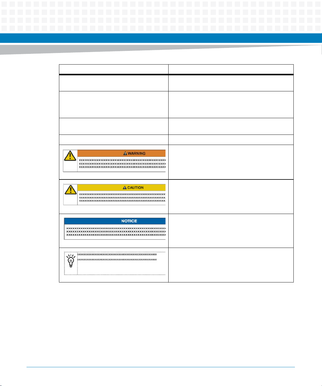
0,1,2,3, and 4 (used in registers)
Indicates a hazardous situation which, if not avoided,
could result in death or serious injury
Indicates a hazardous situation which, if not avoided,
may result in minor or moderate injury
Indicates a property damage message
No danger encountered. Pay attention to important
information
VXS1-RTM1 Installation and Use (6806800P46C)
13
Page 14
About this Manual
Summary of Changes
Part Number Publication Date Description
6806800P46A September 2012 First edition
6806800P46B November 2012 Updated Standard Compliances on page 23 and
6806800P46C April 2015 Re-branded to Artesyn template.
About this Manual
Requirements on page 26.
14
VXS1-RTM1 Installation and Use (6806800P46C)
Page 15

Safety Notes
This section provides warnings that precede potentially dangerous procedures throughout
this manual. Instructions contained in the warnings must be followed during all phases of
operation, service, and repair of this equipment. You should also employ all other safety
precautions necessary for the operation of the equipment in your operating environment.
Failure to comply with these precautions or with specific warnings elsewhere in this manual
could result in personal injury or damage to the equipment.
Artesyn intends to provide all necessary information to install and handle the product in this
manual. Because of the complexity of this product and its various uses, we do not guarantee
that the given information is complete. If you need additional information, ask your Artesyn
representative.
This product is a Safety Extra Low Voltage (SELV) device designed to meet the EN60950-1
requirements for Information Technology Equipment. The use of the product in any other
application may require safety evaluation specific to that application.
Only personnel trained by Artesyn or persons qualified in electronics or electrical engineering
are authorized to install, remove or maintain the product.
The information given in this manual is meant to complete the knowledge of a specialist and
must not be used as replacement for qualified personnel.
Keep away from live circuits inside the equipment. Operating personnel must not remove
equipment covers. Only Factory Authorized Service Personnel or other qualified service
personnel may remove equipment covers for internal subassembly or component replacement
or any internal adjustment.
Do not install substitute parts or perform any unauthorized modification of the equipment or
the warranty may be voided. Contact your local Artesyn representative for service and repair
to make sure that all safety features are maintained.
EMC
This equipment has been tested and found to comply with the limits for a Class A digital device,
pursuant to Part 15 of the FCC Rules. These limits are designed to provide reasonable
protection against harmful interference when the equipment is operated in a commercial
environment. This equipment generates, uses, and can radiate radio frequency energy and, if
not installed and used in accordance with the instruction manual, may cause harmful
interference to radio communications.
VXS1-RTM1 Installation and Use (6806800P46C)
15
Page 16

Safety Notes
Operation of this equipment in a residential area is likely to cause harmful interference in which
case the user will be required to correct the interference at his own expense. Changes or
modifications not expressly approved by Artesyn Embedded Technologies could void the
user's authority to operate the equipment. Board products are tested in a representative
system to show compliance with the above mentioned requirements. A proper installation in
a compliant system will maintain the required performance. Use only shielded cables when
connecting peripherals to assure that appropriate radio frequency emissions compliance is
maintained.
Operation
Product Damage
High humidity and condensation on the board surface causes short circuits.
Do not operate the board outside the specified environmental limits.
Make sure the board is completely dry and there is no moisture on any surface before applying
power.
Damage of Circuits
Electrostatic discharge and incorrect installation and removal can damage circuits or shorten
their life.
Before touching the board or electronic components, make sure that you are working in an
ESD-safe environment.
Board Malfunction
Switches marked as “reserved” might carry production-related functions and can cause the
board to malfunction if their setting is changed.
Do not change settings of switches marked as “reserved”. The setting of switches which are
not marked as “reserved” has to be checked and changed before board installation.
16
VXS1-RTM1 Installation and Use (6806800P46C)
Page 17

Installation
Data Loss
Powering down or removing a board before the operating system or other software running
on the board has been properly shut down may cause corruption of data or file systems.
Make sure all software is completely shut down before removing power from the board or
removing the board from the chassis.
Product Damage
Only use injector handles for board insertion to avoid damage to the front panel and/or PCB.
Deformation of the front panel can cause an electrical short or other board malfunction.
Product Damage
Inserting or removing modules with power applied may result in damage to module
components.
Before installing or removing additional devices or modules, read the documentation that
came with the product.
Safety Notes
Cabling and Connectors
Product Damage
RJ-45 connectors on modules are either twisted-pair Ethernet (TPE) or E1/T1/J1 network
interfaces. Connecting an E1/T1/J1 line to an Ethernet connector may damage your system.
Make sure that TPE connectors near your working area are clearly marked as network
connectors.
Verify that the length of an electric cable connected to a TPE bushing does not exceed 100
meters.
Make sure the TPE bushing of the system is connected only to safety extra low voltage
circuits (SELV circuits).
If in doubt, ask your system administrator.
VXS1-RTM1 Installation and Use (6806800P46C)
17
Page 18

Safety Notes
18
VXS1-RTM1 Installation and Use (6806800P46C)
Page 19

Sicherheitshinweise
Dieses Kapitel enthält Hinweise, die potentiell gefährlichen Prozeduren innerhalb dieses
Handbuchs vorrangestellt sind. Beachten Sie unbedingt in allen Phasen des Betriebs, der
Wartung und der Reparatur des Systems die Anweisungen, die diesen Hinweisen enthalten
sind. Sie sollten außerdem alle anderen Vorsichtsmaßnahmen treffen, die für den Betrieb des
Produktes innerhalb Ihrer Betriebsumgebung notwendig sind. Wenn Sie diese
Vorsichtsmaßnahmen oder Sicherheitshinweise, die an anderer Stelle diese Handbuchs
enthalten sind, nicht beachten, kann das Verletzungen oder Schäden am Produkt zur Folge
haben.
Artesyn Embedded Technologies ist darauf bedacht, alle notwendigen Informationen zum
Einbau und zum Umgang mit dem Produkt in diesem Handbuch bereit zu stellen. Da es sich
jedoch um ein komplexes Produkt mit vielfältigen Einsatzmöglichkeiten handelt, können wir
die Vollständigkeit der im Handbuch enthaltenen Informationen nicht garantieren. Falls Sie
weitere Informationen benötigen sollten, wenden Sie sich bitte an die für Sie zuständige
Geschäftsstelle von Artesyn Embedded Technologies.
Das Produkt wurde entwickelt, um die Sicherheitsanforderungen für SELV Geräte nach der
Norm EN 60950-1 für informationstechnische Einrichtungen zu erfüllen. Die Verwendung des
Produkts in einer anderen Anwendung erfordert eine Sicherheitsüberprüfung für diese
spezifische Anwendung.
Einbau, Wartung und Betrieb dürfen nur von durch Artesyn Embedded Technologies
ausgebildetem oder im Bereich Elektronik oder Elektrotechnik qualifiziertem Personal
durchgeführt werden. Die in diesem Handbuch enthaltenen Informationen dienen
ausschließlich dazu, das Wissen von Fachpersonal zu ergänzen, können dieses jedoch nicht
ersetzen.
Halten Sie sich von stromführenden Leitungen innerhalb des Produktes fern. Entfernen Sie auf
keinen Fall Abdeckungen am Produkt. Nur werksseitig zugelassenes Wartungspersonal oder
anderweitig qualifiziertes Wartungspersonal darf Abdeckungen entfernen, um Komponenten
zu ersetzen oder andere Anpassungen vorzunehmen.
Installieren Sie keine Ersatzteile oder führen Sie keine unerlaubten Veränderungen am Produkt
durch, sonst verfällt die Garantie. Wenden Sie sich für Wartung oder Reparatur bitte an die für
Sie zuständige Geschäftsstelle von Artesyn Embedded Technologies. So stellen Sie sicher, dass
alle sicherheitsrelevanten Aspekte beachtet werden.
VXS1-RTM1 Installation and Use (6806800P46C)
19
Page 20

Sicherheitshinweise
EMV
Das Produkt wurde in einem Artesyn Standardsystem getestet. Es erfüllt die für digitale Geräte
der Klasse A gültigen Grenzwerte in einem solchen System gemäß den FCC-Richtlinien
Abschnitt 15 bzw. EN 55022 Klasse A. Diese Grenzwerte sollen einen angemessenen Schutz
vor Störstrahlung beim Betrieb des Produktes in Gewerbe- sowie Industriegebieten
gewährleisten.
Das Produkt arbeitet im Hochfrequenzbereich und erzeugt Störstrahlung. Bei
unsachgemäßem Einbau und anderem als in diesem Handbuch beschriebenen Betrieb können
Störungen im Hochfrequenzbereich auftreten.
Wird das Produkt in einem Wohngebiet betrieben, so kann dies mit grosser Wahrscheinlichkeit
zu starken Störungen führen, welche dann auf Kosten des Produktanwenders beseitigt werden
müssen. Änderungen oder Modifikationen am Produkt, welche ohne ausdrückliche
Genehmigung von Artesyn Embedded Technologies durchgeführt werden, können dazu
führen, dass der Anwender die Genehmigung zum Betrieb des Produktes verliert.
Boardprodukte werden in einem repräsentativen System getestet, um zu zeigen, dass das
Board den oben aufgeführten EMV-Richtlinien entspricht. Eine ordnungsgemässe Installation
in einem System, welches die EMV-Richtlinien erfüllt, stellt sicher, dass das Produkt gemäss
den EMV-Richtlinien betrieben wird. Verwenden Sie nur abgeschirmte Kabel zum Anschluss
von Zusatzmodulen. So ist sichergestellt, dass sich die Aussendung von
Hochfrequenzstrahlung im Rahmen der erlaubten Grenzwerte bewegt.
Warnung! Dies ist eine Einrichtung der Klasse A. Diese Einrichtung kann im Wohnbereich
Funkstörungen verursachen. In diesem Fall kann vom Betreiber verlangt werden,
angemessene Maßnahmen durchzuführen.
Betrieb
1 Beschädigung des Produktes
Hohe Luftfeuchtigkeit und Kondensat auf der Oberfläche des Produktes können zu
Kurzschlüssen führen.
Betreiben Sie das Produkt nur innerhalb der angegebenen Grenzwerte für die relative
Luftfeuchtigkeit und Temperatur. Stellen Sie vor dem Einschalten des Stroms sicher, dass sich
auf dem Produkt kein Kondensat befindet.
20
VXS1-RTM1 Installation and Use (6806800P46C)
Page 21

Beschädigung von Schaltkreisen
Elektrostatische Entladung und unsachgemäßer Ein- und Ausbau des Produktes kann
Schaltkreise beschädigen oder ihre Lebensdauer verkürzen.
Bevor Sie das Produkt oder elektronische Komponenten berühren, vergewissern Sie sich, daß
Sie in einem ESD-geschützten Bereich arbeiten.
Fehlfunktion des Produktes
Schalter, die mit 'Reserved' gekennzeichnet sind, können mit produktionsrelevanten
Funktionen belegt sein. Das Ändern dieser Schalter kann im normalen Betrieb Störungen
auslösen.
Verstellen Sie nur solche Schalter, die nicht mit 'Reserved' gekennzeichnet sind. Prüfen und ggf.
ändern Sie die Einstellungen der nicht mit 'Reserved' gekennzeichneten Schalter, bevor Sie das
Produkt installieren.
Installation
Sicherheitshinweise
Datenverlust
Das Herunterfahren oder die Deinstallation eines Boards bevor das Betriebssystem oder
andere auf dem Board laufende Software ordnungsmemäss beendet wurde, kann zu
partiellem Datenverlust sowie zu Schäden am Filesystem führen.
Stellen Sie sicher, dass sämtliche Software auf dem Board ordnungsgemäss beendet wurde,
bevor Sie das Board herunterfahren oder das Board aus dem Chassis entfernen.
Beschädigung des Produktes
Fehlerhafte Installation des Produktes kann zu einer Beschädigung des Produktes führen.
Verwenden Sie die Handles, um das Produkt zu installieren/deinstallieren. Auf diese Weise
vermeiden Sie, dass das Face Plate oder die Platine deformiert oder zerstört wird.
Beschädigung des Produktes und von Zusatzmodulen
Fehlerhafte Installation von Zusatzmodulen, kann zur Beschädigung des Produktes und der
Zusatzmodule führen.
Lesen Sie daher vor der Installation von Zusatzmodulen die zugehörige Dokumentation.
VXS1-RTM1 Installation and Use (6806800P46C)
21
Page 22

Sicherheitshinweise
Kabel und Stecker
Beschädigung des Produktes
Bei den RJ-45-Steckern, die sich an dem Produkt befinden, handelt es sich entweder um
Twisted-Pair-Ethernet (TPE) oder um E1/T1/J1-Stecker. Beachten Sie, dass ein versehentliches
Anschließen einer E1/T1/J1-Leitung an einen TPE-Stecker das Produkt zerstören kann.
Kennzeichnen Sie deshalb TPE-Anschlüsse in der Nähe Ihres Arbeitsplatzes deutlich als
Netzwerkanschlüsse.
Stellen Sie sicher, dass die Länge eines mit Ihrem Produkt verbundenen TPE-Kabels 100 m
nicht überschreitet.
Das Produkt darf über die TPE-Stecker nur mit einem Sicherheits-Kleinspannungs-
Stromkreis (SELV) verbunden werden.
Bei Fragen wenden Sie sich an Ihren Systemverwalter.
Umweltschutz
Entsorgen Sie alte Batterien und/oder Blades/Systemkomponenten/RTMs stets gemäß der in
Ihrem Land gültigen Gesetzgebung, wenn möglich immer umweltfreundlich.
22
VXS1-RTM1 Installation and Use (6806800P46C)
Page 23

Introduction
The VXS1-RTM1 is a rear transition module designed to provide I/O expansion of a VME board
through the VME P2 connector and/or the VXS P0 connector. This document describes the
features and functions of the RTM and provides the procedure for hardware preparation and
installation.
1.1 Features
The main features of VXS1-RTM1are as follows:
One Display Port with mini DP connector to RTM panel.
Four serial ports to RTM, two on micro DB9 connectors on RTM panel and two on planar
headers.
Two 10/100/1000BASE-T Ethernet channels to RJ45 connectors on RTM panel
Two USB3.0 ports to RTM with USB type A connectors on RTM panel (one USB3.0 port is
muxed with ESATA port).
Chapter 1
Two ESATA ports to RTM with ESATA connectors on RTM panel (one ESATA port is muxed
with USB3.0 port).
Four GPIOs to planar headers on RTM.
1.2 Standard Compliances
The VXS1-RTM1 is designed to be CE compliant and to meet the following standard
requirements.
Table 1-1 Board Standard Compliances
Standard Description
UL 60950-1
EN 60950-1
IEC 60950-1
CAN/CSA C22.2 No 60950-
1
Safety Requirements (legal)
VXS1-RTM1 Installation and Use (6806800P46C)
23
Page 24

Introduction
Table 1-1 Board Standard Compliances (continued)
Standard Description
CISPR 22
EN 55022
EN 55024
FCC Class A
VCCI Japan
AS/NZS CISPR 22
ETSI EN 300 019 series
Directive 2002/95/EC Directive on the restriction of the use of certain hazardous
EMC requirements (legal) on system level (predefined Artesyn
system)
Environmental Requirements
substances in electrical and electronic equipment (RoHS)
1.3 Mechanical Data
Table 1-2 provides details on the board’s mechanical data.
Table 1-2 Mechanical Data
Characteristic Value
Height 233.44 mm
Depth 80 mm
Width 20.32 mm
Weight 230 g
1.4 Ordering Information
When ordering board variants, use the order number given in the following table.
Model Number Description
VXS1-RTM1 RTM for MVME8100
24
VXS1-RTM1 Installation and Use (6806800P46C)
Page 25

Hardware Preparation and Installation
This chapter describes the preparation before installing the RTM, the applicable environmental
and power requirements, and the actual installation and removal of the RTM.
2.1 Unpacking and Inspecting the RTM
Read all notices and cautions prior to unpacking the product.
Damage of Circuits
Electrostatic discharge and incorrect installation and removal of the blade can damage
circuits or shorten its life.
Before touching the blade or electronic components, make sure that you are working in
an ESD-safe environment.
Chapter 2
Shipment Inspection
To inspect the shipment, perform the following steps:
1. Verify that you have received all items of your shipment:
VXS1-RTM1
One printed copy of Quick Start Guide
One printed copy of Safety Notes Summary
Any other items ordered
VXS1-RTM1 Installation and Use (6806800P46C)
25
Page 26

Hardware Preparation and Installation
2. Check your shipment and report any damage or differences to the contact center at
RMAsupport.ec@artesyn.com.
3. Remove the desiccant bag shipped together with the RTM and dispose of it according to
your country’s legislation.
The RTM is thoroughly inspected before shipment. If any damage occurred during transportation
or any items are missing, contact customer service immediately.
2.2 Requirements
Make sure that the board, when operated in your particular system configuration, meets the
requirements specified in the following sections.
2.2.1 Environmental Requirements
The following table lists the currently available specifications for the environmental
characteristics of the VXS1-RTM1. A complete functional description of the VXS1-RTM1
baseboard appears in Chapter 4, Functional Description.
Operating temperatures refer to the temperature of the air circulating around the board and not
to the component temperature.
Table 2-1 VXS1-RTM1 Specifications
Characteristics Value
Cooling Method Forced Air
Operating temperature 0°C to +55°C
Storage Temperature -40°C to +85°C
26
VXS1-RTM1 Installation and Use (6806800P46C)
Page 27

Table 2-1 VXS1-RTM1 Specifications (continued)
Characteristics Value
Relative humidity To 95% RH
Hardware Preparation and Installation
Vibration Sine
(10min/axis)
Vibration Random
(1hr/axis)
Shock 20g/11mS
2G, 5 to 500Hz
0.002g2/Hz, 15
to 2000 Hz
Product Damage
High humidity and condensation on the board surface causes short circuits.
Do not operate the board outside the specified environmental limits.
Make sure the board is completely dry and there is no moisture on any surface before applying
power.
2.2.2 Power Requirements
The RTM uses +5 V as a primary power source from the RP2 connector and converts to other
voltages internally using on board DC-DC converter. The following table shows the power
source required.
Table 2-2 Operating Voltages
Voltage Minimum Nominal Maximum
+5.0V 4.875V (-2.5%) 5.0V 5.25V (+5%)
VXS1-RTM1 Installation and Use (6806800P46C)
27
Page 28

Hardware Preparation and Installation
The power requirements for the RTM are as follows:
Table 2-3 Power Requirements
RTM CONFIGURATION +5.0V TOTAL POWER
Air Cooled 0.25 A 1.25 W
2.3 RTM Installation and Removal
The RTM does not support hot swap, you should remove power to the rear slot or system
before installing the module. Before installing the transition module, you may need to
manually configure the switch and install a PMC I/O Module (PIM).
Damage of Circuits
Electrostatic discharge and incorrect installation and removal can damage circuits or shorten
their life.
Before touching the board or electronic components, make sure that you are working in an ESDsafe environment.
Product Damage
Only use injector handles for board insertion to avoid damage to the front panel and/or PCB.
Deformation of the front panel can cause an electrical short or other board malfunction.
Board Malfunction
Switches marked as “reserved” might carry production-related functions and can cause the
board to malfunction if their setting is changed.
Do not change settings of switches marked as “reserved”. The setting of switches which are not
marked as “reserved” has to be checked and changed before board installation.
28
VXS1-RTM1 Installation and Use (6806800P46C)
Page 29

Hardware Preparation and Installation
Installation Procedure
To begin the installation of the RTM in a chassis, proceed as follows:
1. Turn all equipment power OFF and disconnect the power cable from the AC power
source.
2. Remove the chassis cover as instructed in the equipment user's manual.
3. Remove the filler panel(s) from the appropriate card slot(s) at the rear of the chassis
(if the chassis has a rear card cage).
4. Install the top and bottom edge of the RTM into the rear guides of the chassis.
5. Ensure that the levers of the two injector/ejectors are in the outward position.
6. Slide the RTM into the chassis until resistance is felt.
7. Simultaneously move the injector/ejector levers in an inward direction.
8. Verify that the RTM is properly seated and secure it to the chassis using the two
screws located adjacent to the injector/ejector levers.
9. Connect the appropriate cables to the RTM.
Removal Procedure
1. Attach an ESD strap to your wrist. Attach the other end of the ESD strap to the
chassis as a ground. The ESD strap must be secured to your wrist and the chassis to
ground throughout
the procedure.
2. Turn off the power.
3. Disconnect the appropriate cables from the RTM.
4. Press the red locking tabs (IEEE handles only) to extract the board.
5. Loosen and remove the screws located adjacent to the injector/ejector levers that
securing board to the chassis.
6. Move the injector/ejector levers in outward direction.
VXS1-RTM1 Installation and Use (6806800P46C)
29
Page 30

Hardware Preparation and Installation
7. Hold top and bottom edges of the RTM and exert minimal force when pulling RTM
from the chassis to prevent pin damage.
8. Carefully remove the RTM from the chassis and store in an anti-static envelope.
9. Install the filler panel into the appropriate slots at the rear of the chassis.
30
VXS1-RTM1 Installation and Use (6806800P46C)
Page 31

Controls, LEDs, and Connectors
This chapter summarizes the controls, LEDs, and connectors of the MVME8100 baseboard.
3.1 Front Panel
The following switch, LEDs, and connectors are available on the VXS1-RTM1 front panel. Refer
Figure 3-1 for the location of each.
Figure 3-1 Front Panel LEDs, Connectors, Switch
Chapter 3
VXS1-RTM1 Installation and Use (6806800P46C)
31
Page 32

Controls, LEDs, and Connectors
3.1.1 Front Panel LEDS
Table 3-1 describes the LEDs on the front panel of the RTM. Refer to Figure 3-1 for LED
locations.
Table 3-1 Front Panel LEDs
Label Function Color Description
GENET 1
Speed
GENET 1
ACT
GENET 2
Speed
GENET 2
ACT
Gigabit
Ethernet 1
Link Speed
Gigabit
Ethernet 1
Activity
Gigabit
Ethernet 2
Speed
Gigabit
Ethernet 2
Activity
OFF No Link
Yellow 10/100 BASE-T Operation
Green 1000 BASE-T Operation
Off No activity
Blinking
Green
OFF No Link
Yellow 10/100 BASE-T Operation
Green 1000 BASE-T Operation
Off No activity
Blinking
Green
Activity proportional to bandwidth utilization
Activity proportional to bandwidth utilization
32
VXS1-RTM1 Installation and Use (6806800P46C)
Page 33

3.1.2 Connectors
This section describes the pin assignments and signals for the connectors on the RTM.
3.1.2.1 Connector Definitions
The following table lists the connectors located on the RTM.
Table 3-2 RTM Connectors
Reference
Designator Function Pinout Definition Description
RP0 VXS Backplane RP0 Custom High speed connector
RP2 VME Backplane RP2 VITA 1 VME / User I/O connector
P1 Reset Planar connector for
Controls, LEDs, and Connectors
recessed switch on front
panel
P2 CPLD Programmer and
I2C debug
P3 Serial Port Ten pins planar header
P4 Serial Port Ten pins planar header
P5 GPIO Eight pins planar header
J1 Mini Display VESA VESA mini display
J2 Serial Port DTE Mini DB9 serial port 2
J3 Serial Port DTE Mini DB9 serial port 1
J4 USB Dual stacked USB3.0
VXS1-RTM1 Installation and Use (6806800P46C)
Ten pins planar header for
CPLD programming and
I2C debugging
connector for Serial Port 3
connector for Serial Port 4
connector for GPIO lines
connector on front panel
connector on front panel
connector on front panel
connector for USB 1 and 2
on front panel
33
Page 34

Controls, LEDs, and Connectors
Table 3-2 RTM Connectors (continued)
Reference
Designator Function Pinout Definition Description
J5 Dual Ethernet Dual Ethernet RJ45 with
J6 eSATA Dual stacked eSATA Port
J10, J14 PIM I/O I/O connector for PMC
S1 DIP Switch Six position switch for
3.1.2.2 RTM Connectors
magnetics connector on
front panel
1 and 2 connector on
front panel
rear signals
EEPROM address
selection
The following sections describe the pin out of headers and connectors used on the RTM.
3.1.2.2.1 VME/VXS RP0 Connector
This high speed connector is defined by VITA41.7 standard. This connector is used to connect
high speed signals such as USB3.0, DisplayPort, SATA etc.
The pin assignment is shown in the table below:
Table 3-3 RTM RP0 Connector Pin Assignment
RTM
Board
RP0
Bplan
e RJ0 Row I Row H Row G Row F Row E Row D Row C Row B Row A
1 VOID GND GND VOID VOID GND GND VOID VOID
2 VOID VOID VOID VOID VOID VOID VOID VOID VOID
3 VOID VOID VOID VOID VOID VOID VOID VOID VOID
34
Row G Row F Row E Row D Row C Row B Row A
Even Odd Even Odd
VXS1-RTM1 Installation and Use (6806800P46C)
Page 35

Table 3-3 RTM RP0 Connector Pin Assignment (continued)
Controls, LEDs, and Connectors
RTM
Board
RP0
Bplan
e RJ0 Row I Row H Row G Row F Row E Row D Row C Row B Row A
4 VOID VOID VOID VOID VOID VOID VOID VOID VOID
5 DPC_HPD GND GND SGMII_T
6 GND DPC_D0_NDPC_
7 GPIO<0> GND GND DPC_D2_NDPC_D2_PGND GND DPC_D3_N DPC_D3_P
8 GND USB2_SS
9 GPIO<1> GND GND SATA2_
10 GND SATA1_T
Row G Row F Row E Row D Row C Row B Row A
Even Odd Even Odd
TX_N
X_N
D0_P
USB2
_SSTX
_P
SATA1
_TX_P
SGMII_TX
X0_N(N
C)
GND GND DPC_D
GND GND USB2_S
USB1_S
STX_N
GND GND SATA1_
0_P(NC)
SATA2_US
B1_SSTX_
P
GND GND SGMII_RX0
_N(NC)
DPC_
1_N
SRX_N
GND GND SATA2_USB
RX_N
D1_P
USB2_
SSRX_
P
SATA1
_RX_P
GND GND
GND GND
1_SSRX_N
GND GND
SGMII_RX
0_P(NC)
SATA2_US
B1_SSRX_
P
11 PEN* (NC) GND GND SGMII_T
X1_N(N
C)
12 VOID GND GND VOID VOID GND GND VOID VOID
13 VOID VOID VOID VOID VOID VOID VOID VOID VOID
14 VOID VOID VOID VOID VOID VOID VOID VOID VOID
15 VOID VOID VOID VOID VOID VOID VOID VOID VOID
VXS1-RTM1 Installation and Use (6806800P46C)
SGMII_TX
1_P(NC)
GND GND SGMII_RX1
_N(NC)
SGMII_RX
1_P(NC)
35
Page 36

Controls, LEDs, and Connectors
3.1.2.2.2 VME RP2 Connector
The 32 pins in each row connector is defined by VME standard. This connector is used to
connect PMC I/Os, COM ports, USB2.0 and other I/O signals. The pin assignment is shown in
the table below:
Table 3-4 RP2 Pin Assignment
1st Row 2nd Row 3rd Row 4th Row 5th Row
Pin
Name
A1 PMC_IO<2> B1 +5V C1 PMC_IO<1> D1 DPC_BP_AUX_PZ1 GIGE1_TR
A2 PMC_IO<4> B2 GND C2 PMC_IO<3> D2 DPC_BP_AUX_NZ2 GND
A3 PMC_IO<6> B3 NC C3 PMC_IO<5> D3 GND Z3 GIGE1_TR
A4 PMC_IO<8> B4 NC C4 PMC_IO<7> D4 USB1_P Z4 GND
A5 PMC_IO<10> B5 NC C5 PMC_IO<9> D5 USB1_N Z5 GIGE1_TR
A6 PMC_IO<12> B6 NC C6 PMC_IO<11>D6 GND Z6 GND
A7 PMC_IO<14> B7 NC C7 PMC_IO<13>D7 USB2_DBG_P Z7 GIGE1_TR
A8 PMC_IO<16> B8 NC C8 PMC_IO<15>D8 USB2_DBG_N Z8 GND
A9 PMC_IO<18> B9 NC C9 PMC_IO<17>D9 RTM_SIO Z9 GIGE1_TR
A10 PMC_IO<20> B10 NC C10 PMC_IO<19>D10 RTM_RST_L Z10 GND
Signal Name Pin
Name
Signal
Name
Pin
Name
Signal Name Pin
Name
Signal Name Pin
Name
Signal
Name
D0_P
D0_N
D1_P
D1_N
D2_P
A11 PMC_IO<22> B11 NC C11 PMC_IO<21>D11 BP_GPIO2 Z11 GIGE1_TR
D2_N
A12 PMC_IO<24> B12 GND C12 PMC_IO<23>D12 BP_GPIO3 Z12 GND
A13 PMC_IO<26> B13 +5V C13 PMC_IO<25>D13 I2C_SDA Z13 GIGE1_TR
D3_P
36
VXS1-RTM1 Installation and Use (6806800P46C)
Page 37

Controls, LEDs, and Connectors
Table 3-4 RP2 Pin Assignment (continued)
1st Row 2nd Row 3rd Row 4th Row 5th Row
Pin
Name
A14 PMC_IO<28> B14 NC C14 PMC_IO<27>D14 I2C_SCL Z14 GND
A15 PMC_IO<30> B15 NC C15 PMC_IO<29>D15 COM1_RX_C
A16 PMC_IO<32> B16 NC C16 PMC_IO<31>D16 COM1_RX_C
A17 PMC_IO<34> B17 NC C17 PMC_IO<33>D17 COM2_RX_C
A18 PMC_IO<36> B18 NC C18 PMC_IO<35>D18 COM2_RX_C
A19 PMC_IO<38> B19 NC C19 PMC_IO<37>D19 COM3_RX_C
A20 PMC_IO<40> B20 NC C20 PMC_IO<39>D20 COM3_RX_C
A21 PMC_IO<42> B21 NC C21 PMC_IO<41>D21 COM4_RX_C
A22 PMC_IO<44> B22 GND C22 PMC_IO<43>D22 COM4_RX_C
A23 PMC_IO<46> B23 NC C23 PMC_IO<45>D23 COM1_TX_R
Signal Name Pin
Name
Signal
Name
Pin
Name
Signal Name Pin
Name
Signal Name Pin
Name
Z15 GIGE1_TR
TS_A_P
Z16 GND
TS_A_N
Z17 GIGE2_TR
TS_A_P
Z18 GND
TS_A_N
Z19 GIGE2_TR
TS_A_P
Z20 GND
TS_A_N
Z21 GIGE2_TR
TS_A_P
Z22 GND
TS_A_N
Z23 GIGE2_TR
TS_A_P
Signal
Name
D3_N
D0_P
D0_N
D1_P
D1_N
A24 PMC_IO<48> B24 NC C24 PMC_IO<47>D24 COM1_TX_R
TS_A_N
A25 PMC_IO<50> B25 NC C25 PMC_IO<49>D25 COM2_TX_R
TS_A_P
A26 PMC_IO<52> B26 NC C26 PMC_IO<51>D26 COM2_TX_R
TS_A_N
A27 PMC_IO<54> B27 NC C27 PMC_IO<53>D27 COM3_TX_R
TS_A_P
A28 PMC_IO<56> B28 NC C28 PMC_IO<55>D28 COM3_TX_R
TS_A_N
VXS1-RTM1 Installation and Use (6806800P46C)
Z24 GND
Z25 GIGE2_TR
D2_P
Z26 GND
Z27 GIGE2_TR
D2_N
Z28 GND
37
Page 38

Controls, LEDs, and Connectors
Table 3-4 RP2 Pin Assignment (continued)
1st Row 2nd Row 3rd Row 4th Row 5th Row
Pin
Name
A29 PMC_IO<58> B29 NC C29 PMC_IO<57>D29 COM4_TX_R
A30 PMC_IO<60> B30 NC C30 PMC_IO<59>D30 COM4_TX_R
A31 PMC_IO<62> B31 GND C31 PMC_IO<61>D31 GND Z31 GIGE2_TR
A32 PMC_IO<64> B32 +5V C32 PMC_IO<63>D32 +5V Z32 GND
Signal Name Pin
Name
Signal
Name
Pin
Name
Signal Name Pin
Name
Signal Name Pin
Name
Z29 GIGE2_TR
TS_A_P
Z30 GND
TS_A_N
Signal
Name
D3_P
D3_N
3.1.2.2.3 RTM Mini Display Connector J1
The RTM provides one mini Display connector on its front panel for connecting display port
capable display devices to display port capable front blades. The pin assignment for this
connector is as follows:
Table 3-5 RTM Mini Display Port Connector (J1)
Pin Name Signal Name
1GND
2 HPD_IN
38
3 ML_LANE0_P
4 CAD_IN
5 ML_LANE0_N
6 10M ohm to GND
7GND
8GND
9 ML_LANE1_P
10 ML_LANE3_P
11 ML_LANE1_N
VXS1-RTM1 Installation and Use (6806800P46C)
Page 39

Table 3-5 RTM Mini Display Port Connector (J1) (continued)
Pin Name Signal Name
12 ML_LANE3_N
13 GND
14 GND
15 ML_LANE2_P
16 DPC_AUX_P
17 ML_LANE2_N
18 DPC_AUX_N
19 GND
20 +3V3
3.1.2.2.4 RTM Serial Port 1 Connector J3
Controls, LEDs, and Connectors
The RTM provides one standard mini-9 serial port connector on its front panel. The pin
assignment for this connector is as follows:
Table 3-6 RTM COM 1 Connector (J3)
Pin Name Signal Name
1NC
2 COM1_RX_CTS_P
3 COM1_TX_RTS_P
4NC
5GND
6NC
7 COM1_TX_RTS_N
8 COM1_RX_CTS_N
9NC
VXS1-RTM1 Installation and Use (6806800P46C)
39
Page 40

Controls, LEDs, and Connectors
3.1.2.2.5 RTM Serial Port 2 Connector J2
The RTM provides one standard mini-9 serial port connector on its front panel. The pin
assignment for this connector is as follows:
Table 3-7 RTM COM 2 Connector (J2)
Pin Name Signal Name
1NC
2 COM2_RX_CTS_P
3 COM2_TX_RTS_P
4NC
5GND
6NC
7 COM2_TX_RTS_N
8 COM2_RX_CTS_N
9NC
3.1.2.2.6 RTM Serial Port 3 Connector P3
The RTM provides one planar header for COM port 3. The pin assignment for this connector is
as follows:
Table 3-8 RTM COM 3 Header (P3)
Pin Name Signal Name
1NC
2 COM3_RX_CTS_P
3 COM3_TX_RTS_P
4NC
5GND
6NC
7 COM3_TX_RTS_N
8 COM3_RX_CTS_N
40
VXS1-RTM1 Installation and Use (6806800P46C)
Page 41

Table 3-8 RTM COM 3 Header (P3) (continued)
Pin Name Signal Name
9NC
10 NC
3.1.2.2.7 RTM Serial Port 4 Connector P4
The RTM provides one planar header for COM port 4. The pin assignment for this connector is
as follows:
Table 3-9 RTM COM 4 Header (P4)
Pin Name Signal Name
1NC
2 COM4_RX_CTS_P
Controls, LEDs, and Connectors
3 COM4_TX_RTS_P
4NC
5GND
6NC
7 COM4_TX_RTS_N
8 COM4_RX_CTS_N
9NC
10 NC
3.1.2.2.8 RTM USB 1 and USB 2 Connector J4
The RTM provides one standard dual stacked USB port 1 and 2 type A connector on its front
panel. Both ports provide USB 3.0 capability and backward compatible with USB 2.0. The pin
assignment for this connector is as follows:
Table 3-10 RTM Dual USB 1 and 2 Connector (J4)
Pin Name Signal Name
1 USB1_+5V
VXS1-RTM1 Installation and Use (6806800P46C)
41
Page 42

Controls, LEDs, and Connectors
Table 3-10 RTM Dual USB 1 and 2 Connector (J4) (continued)
Pin Name Signal Name
2 USB1_N
3 USB1_P
4GND
5 USB1_SSRX_N
6 USB1_SSRX_P
7GND
8 USB1_SSTX_N
9 USB1_SSTX_P
10 USB2_+5V
11 USB2_N
12 USB2_P
13 GND
14 USB2_SSRX_N
15 USB2_SSRX_P
16 GND
17 USB2_SSTX_N
18 USB2_SSTX_P
3.1.2.2.9 RTM Dual Ethernet Connector J5
The RTM provides one dual ethernet connector on its front panel for connecting 1000BASE-T
Ethernet. The pin assignment for this connector is as follows:
Table 3-11 RTM Dual Ethernet Connector (J5)
Pin Name Signal Name Pin Name Signal Name
1A GND_PE 1B GND_PE
2A NC 2B NC
3A GIGE1_TRD3_P 3B GIGE2_TRD3_P
42
VXS1-RTM1 Installation and Use (6806800P46C)
Page 43

Controls, LEDs, and Connectors
Table 3-11 RTM Dual Ethernet Connector (J5) (continued)
Pin Name Signal Name Pin Name Signal Name
4A GIGE1_TRD3_N 4B GIGE2_TRD3_N
5A GIGE1_TRD2_P 5B GIGE2_TRD2_P
6A GIGE1_TRD2_N 6B GIGE2_TRD2_N
7A GIGE1_TRD1_P 7B GIGE2_TRD1_P
8A GIGE1_TRD1_N 8B GIGE2_TRD1_N
9A GIGE1_TRD0_P 9B GIGE2_TRD0_P
10A GIGE1_TRD0_N 10B GIGE2_TRD0_N
D1A GIGE1_LINK1_L D1B GIGE2_LINK1_L
D2A GIGE1_LINK2_L D2B GIGE2_LINK2_L
D3A GIGE1_LED1_PWR D3B GIGE2_LED1_PWR
D4A GIGE1_ACT_L D4B GIGE2_ACT_L
3.1.2.2.10 RTM eSATA Port 1 and 2 Connector J6
The RTM provides one dual stacked eSATA connector on its front panel. The pin assignment for
this connector is as follows:
Table 3-12 Dual eSATA Connector (J6)
Pin Name Signal Name
A1 GND
A2 ESATA1_TX_P
A3 ESATA1_TX_N
A4 GND
A5 ESATA1_RX_N
A6 ESATA1_RX_P
A7 GND
B1 GND
B2 ESATA2_TX_P
VXS1-RTM1 Installation and Use (6806800P46C)
43
Page 44

Controls, LEDs, and Connectors
Table 3-12 Dual eSATA Connector (J6) (continued)
Pin Name Signal Name
B3 ESATA2_TX_N
B4 GND
B5 ESATA2_RX_N
B6 ESATA2_RX_P
B7 GND
3.1.2.2.11 RTM PIM Connector J10
The RTM provides two PMC connectors J10 and J14 for PMC rear I/Os signals. These connectors
are used to install PIM module. The pin assignment of J10 connector is shown below. The pin
assignment of J14 is shown in Table 3-14.
Table 3-13 PIM Connector (J10)
Pin Name Signal Name Pin Name Signal Name
1NC33NC
2NC34GND
3NC35NC
4NC36NC
5 +5V_RTM 37 +5V_RTM
6NC38NC
7NC39NC
8NC40NC
9NC41NC
10 +3V3_RTM 42 +3V3_RTM
11 NC 43 NC
12 NC 44 NC
13 GND 45 GND
14 NC 46 NC
44
VXS1-RTM1 Installation and Use (6806800P46C)
Page 45

Controls, LEDs, and Connectors
Table 3-13 PIM Connector (J10) (continued)
Pin Name Signal Name Pin Name Signal Name
15 NC 47 NC
16 NC 48 NC
17 NC 49 NC
18 GND 50 GND
19 NC 51 NC
20 NC 52 NC
21 +5V_RTM 53 +5V_RTM
22 NC 54 NC
23 NC 55 NC
24 NC 56 NC
25 NC 57 NC
26 +3V3_RTM 58 +3V3_RTM
27 NC 59 NC
28 NC 60 NC
29 GND 61 NC
30 NC 62 NC
31 NC 63 NC
32 NC 64 NC
3.1.2.2.12 RTM PIM Connector J14
The RTM provides two PMC connectors J10 and J14 for PMC rear I/Os signals. These connectors
are used to install PIM module. The pin assignment of J14 connector is shown below.
Table 3-14 PIM Connector (J14)
Pin Name Signal Name Pin Name Signal Name
1 PMC_IO<1> 33 PMC_IO<33>
2 PMC_IO<2> 34 PMC_IO<34>
VXS1-RTM1 Installation and Use (6806800P46C)
45
Page 46

Controls, LEDs, and Connectors
Table 3-14 PIM Connector (J14) (continued)
Pin Name Signal Name Pin Name Signal Name
3 PMC_IO<3> 35 PMC_IO<35>
4 PMC_IO<4> 36 PMC_IO<36>
5 PMC_IO<5> 37 PMC_IO<37>
6 PMC_IO<6> 38 PMC_IO<38>
7 PMC_IO<7> 39 PMC_IO<39>
8 PMC_IO<8> 40 PMC_IO<40>
9 PMC_IO<9> 41 PMC_IO<41>
10 PMC_IO<10> 42 PMC_IO<42>
11 PMC_IO<11> 43 PMC_IO<43>
12 PMC_IO<12> 44 PMC_IO<44>
13 PMC_IO<13> 45 PMC_IO<45>
46
14 PMC_IO<14> 46 PMC_IO<46>
15 PMC_IO<15> 47 PMC_IO<47>
16 PMC_IO<16> 48 PMC_IO<48>
17 PMC_IO<17> 49 PMC_IO<49>
18 PMC_IO<18> 50 PMC_IO<50>
19 PMC_IO<19> 51 PMC_IO<51>
20 PMC_IO<20> 52 PMC_IO<52>
21 PMC_IO<21> 53 PMC_IO<53>
22 PMC_IO<22> 54 PMC_IO<54>
23 PMC_IO<23> 55 PMC_IO<55>
24 PMC_IO<24> 56 PMC_IO<56>
25 PMC_IO<25> 57 PMC_IO<57>
26 PMC_IO<26> 58 PMC_IO<58>
27 PMC_IO<27> 59 PMC_IO<59>
28 PMC_IO<28> 60 PMC_IO<60>
29 PMC_IO<29> 61 PMC_IO<61>
VXS1-RTM1 Installation and Use (6806800P46C)
Page 47

Table 3-14 PIM Connector (J14) (continued)
Pin Name Signal Name Pin Name Signal Name
30 PMC_IO<30> 62 PMC_IO<62>
31 PMC_IO<31> 63 PMC_IO<63>
32 PMC_IO<32> 64 PMC_IO<64>
3.1.2.2.13 RTM Reset Connector P1
The RTM provides one 2 pin planar header to connect reset switch on its front panel. The pin
assignment for this connector is as follows:
Table 3-15 RTM Reset Switch Connector (P1)
PIN# SIGNAL
1 RTM_RST#
Controls, LEDs, and Connectors
2GND
3.1.2.2.14 RTM CPLD Programming and Debug Connector P2
The RTM provides one 10 pin planar header to connect JTAG signals to program CPLD. The
connector also provides access to I2C bus for de-bugging. The pin assignment of this connector
is as follows:
Table 3-16 RTM CPLD Programming & Debug Header (P2)
Pin Name Signal Name
1 +3V3
2TMS
3NC
4TCK
5NC
6 TDI
7 I2C_SCL
8 TDO
VXS1-RTM1 Installation and Use (6806800P46C)
47
Page 48

Controls, LEDs, and Connectors
Table 3-16 RTM CPLD Programming & Debug Header (P2) (continued)
Pin Name Signal Name
9 I2C_SDA
10 GND
3.1.2.2.15 RTM GPIO Connector P5
The RTM provides one 8 pin planar header connector for GPIO signals. The pin assignment of
this connector is as follows:
Table 3-17 GPIO Header (P5)
Pin Name Signal Name
1GPIO0
2GND
3GPIO1
4GND
5GPIO2
6GND
7GPIO3
8GND
3.1.3 Switches
One 6 position switch is provided for RTM. The default setting on all switch positions is OFF.
3.1.3.1 RTM Configuration Switch
Pin assignment of RTM switch S1 is shown below:
Table 3-18 RTM Configuration Switch (S1)
Pin Name Signal Name ON OFF
SW6 SW2_CPLD Reserved
48
VXS1-RTM1 Installation and Use (6806800P46C)
Page 49

Controls, LEDs, and Connectors
Table 3-18 RTM Configuration Switch (S1) (continued)
Pin Name Signal Name ON OFF
SW5 SW1_CPLD Reserved
SW4 I2C_WP Write protect RTM VPD
SW3 I2C_ADDR0 RTM VPD EEPROM Address A0, ON=0, OFF=1
SW2 I2C_ADDR1 RTM VPD EEPROM Address A1, ON=0, OFF=1
SW1 I2C_ADDR2 RTM VPD EEPROM Address A2, ON=0, OFF=1
3.1.3.2 RTM FRU EEPROM
The RTM provides a 2Kb serial EEPROM containing FRU configuration information specific to
the RTM. Typical information that may be present in the EEPROM include: manufacturer, board
revision, build version, date of assembly etc. The RTM FRU EEPROM device address is user
selectable through the switch with the default address of 0x57. Refer to the EEPROM datasheet
for additional details and/or programming information.
EEPROM
Allow to write RM VPD
EEPROM
VXS1-RTM1 Installation and Use (6806800P46C)
49
Page 50

Controls, LEDs, and Connectors
50
VXS1-RTM1 Installation and Use (6806800P46C)
Page 51

Functional Description
The RTM provides rear panel access to four serial ports, two 10/100/1000 Ethernet ports with
RJ45 connectors, two USB3.0 with dual stacked type A connectors (one of USB3.0 port is
multiplexed with eSATA port), one Display Port with mini DP connector, two eSATA ports, and
one PIM slot with front I/O. The Figure 4-1 shows the block diagram of RTM.
4.1 Block Diagram
Figure 4-1 illustrates the VXS1-RTM1 architecture.
Figure 4-1 Block Diagram
iVME7300/MVME8100 RTM
DB9
DB9
Dual
RJ45
Dual
USB3.0
Dual
eSATA
Mini
DP
Chapter 4
PIM Front Panel
MAG
RS-xxx
Fro nt Rese t
Header
RS-xxx
RS- xx x
RS-xxx
RP2
1000BASE-T
USB 3. 0
USB3.0
1000BASE-T
Re-driver
USB3.0
Re-driver
USB 3. 0
SATA
Re-driver
RP0
SATA, G3SATA
SATA
Re-driver
SATA SATA, G2
Header
4x GPIOs
Dis pl ayPo rt
USB2.0
USB2.0(Debug)
VPD
8KB
I2C
Lattice
MachXO2
CPLD
RP2
PIM Connector
PMC1 P4 I/Os
RTM_SIO
VXS1-RTM1 Installation and Use (6806800P46C)
51
Page 52

Functional Description
4.2 Ethernet Interfaces
The Ethernets are 10/100/1000 BASE-T based, Gigabit ethernet. It is routed to the RTM panel
on RJ45 connector with integrated magnetics and LED.
4.3 Serial COM Ports
Two of the COM ports routed to RTM are provided on micro DB9 connectors at RTM panel,
while remaining two RTM COM ports are provided on planar headers.
4.4 USB Interface
USB3.0 ports 1 and 2 are routed to RTM through the RP2 and RP0 connectors.
Both ports can operate simultaneously in USB 2.0 mode using signal routed through RP2. Port
2 has dedicated USB 3.0 signal connections to RP0 so Port 2 is a dedicated USB 3.0 port. Port 1
has USB 3.0 signals which are shared with the SATA 2 port and controlled by an on board mux.
An RTM can support two USB3.0 or two eSATA or one USB3.0 and one eSATA combinations on
multiplexed lines, as per the user requirement. The selection is controlled by a select signal
contained in a serial IO bitstream from the front blade. When USB3.0 ports are not supported
on the front blade, the corresponding USB2.0 ports are still supported and can be used on
RTM.
4.5 Display Interface
A display port is configured as DisplayPort or DVI can be routed to RTM through backplane
connector P0. A level shifter is provided on RTM to support either DisplayPort or DVI signaling
levels.
52
VXS1-RTM1 Installation and Use (6806800P46C)
Page 53

4.6 SATA Interface
Port 1 and 2 are routed to RTM through backplane P0 connector where they are available on
eSATA connectors on face plate. Port 2 is also multiplexed with Port1 USB3.0 lines. An RTM can
support two USB3.0 or two eSATA or one USB3.0, and one eSATA combinations on multiplexed
lines, as per the user requirement. The selection is controlled by a select signal contained in a
serial IO bit stream from the front blade.
4.7 GPIO Interface
The RTM provides 4 GPIO signals from the front board FPGA. All 4 GPIO signals are routed to
RTM through backplane connector P0 and P2.
4.8 Power Supply Sources
Functional Description
All RTM power is supplied from the VME +5 V supply through the RP2 connector. The RTM has
an on-board +3.3 V power supply derived from +5 V.
VXS1-RTM1 Installation and Use (6806800P46C)
53
Page 54

Functional Description
54
VXS1-RTM1 Installation and Use (6806800P46C)
Page 55

Appendix A
A Related Documentation
A.1 Artesyn Embedded Technologies - Embedded
Computing Documentation
The publications listed below are referenced in this manual. You can obtain electronic copies of
Artesyn Embedded Technologies - Embedded Computing publications by contacting your
local Artesyn sales office. For released products, you can also visit our Web site for the latest
copies of our product documentation.
1. Go to www.artesyn.com/computing/support/product/technical-documentation.php.
2. Under FILTER OPTIONS, click the Document types drop-down list box to select the type of
document you are looking for.
3. In the Search text box, type the product name and click GO.
Table A-1 Artesyn Embedded Technologies - Embedded Computing Publications
Document Title Publication Number
MVME8100 Programmer’s Reference 6806800P28
MVME8100 Installation and Use 6806800P25
A.2 Related Specifications
For additional information, refer to the following table for related specifications. As an
additional help, a source for the listed document is provided. Please note that, while these
sources have been verified, the information is subject to change without notice.
Table A-2 Related Specifications
Organization and Standard Document Title
VITA Standards Organization
VME64 ANSI/VITA 1-1994
Processor PMC ANSI/VITA 32-2003
XMC Switched Mezzanine Card Auxiliary Standard, September 2005 VITA 42.0-2005
Conduction Cooled PMC ANSI/VITA 20 - 2001
VXS1-RTM1 Installation and Use (6806800P46C)
55
Page 56

Related Documentation
Table A-2 Related Specifications (continued)
Organization and Standard Document Title
PMC I/O Module (PIM) Draft Standard VITA 36
Universal Serial Bus
Universal Serial Bus Specification Revision 2.0
Institute for Electrical and Electronics Engineers, Inc.
IEEE Standard for a Common Mezzanine Card Family: CMC IEEE1386
Draft Rev 0.1
July 19, 1999
April 27, 2000
Oct 25, 2001
IEEE Standard Physical and Environmental Layer for PCI Mezzanine
Cards: PMC
Additional Mechanical Specifications IEEE 1101.10 - 1996
IEEE Standard for Mechanical Core Specifications for
Microcomputers
A.3 Manufacturers’ Documents
For additional information, refer to the following table for manufacturers’ data sheets or user’s
manuals. As an additional help, a source for the listed document is provided. Please note that,
while these sources have been verified, the information is subject to change without notice.
Table A-3 Manufacturer’s Publications
Document Title and Source Publication Number
Freescale Corporation
P5020/P5010 QorIQ Integrated Processor Hardware Specifications P5020EC
P5020 QorIQ Integrated Multicore Communication Processor
Reference Manual
IEEE1386.1
Oct 25, 2001
IEEE 1101.1 - 1998
P5020RM
56
VXS1-RTM1 Installation and Use (6806800P46C)
Page 57

Page 58

Artesyn Embedded Technologies, Artesyn and the Artesyn Embedded Technologies logo are trademarks and service marks of Artesyn Embedded Technologies, Inc.
All other product or service names are the property of their respective owners.
©
2015 Artesyn Embedded Technologies, Inc.
 Loading...