

Artesyn MVME7100 Installation

MVME7100 Single Board Computer
Installation and Use
P/N: 6806800E08D
June 2014

©
Copyright 2014 Artesyn Embedded Technologies, Inc.
All rights reserved.
Trademarks
Artesyn Embedded Technologies, Artesyn and the Artesyn Embedded Technologies logo are trademarks and service marks of
Artesyn Embedded Technologies, Inc.© 2014 Artesyn Embedded Technologies, Inc. All other product or service names are the
property of their respective owners.
Intel® is a trademark or registered trademark of Intel Corporation or its subsidiaries in the United States and other countries.
Java™ and all other Java-based marks are trademarks or registered trademarks of Oracle America, Inc. in the U.S. and other countries.
Microsoft®, Windows® and Windows Me® are registered trademarks of Microsoft Corporation; and Windows XP™ is a trademark of
Microsoft Corporation.
PICMG®, CompactPCI®, AdvancedTCA™ and the PICMG, CompactPCI and AdvancedTCA logos are registered trademarks of the PCI
Industrial Computer Manufacturers Group.
UNIX® is a registered trademark of The Open Group in the United States and other countries.
Notice
While reasonable efforts have been made to assure the accuracy of this document, Artesyn assumes no liability resulting from any
omissions in this document, or from the use of the information obtained therein. Artesyn reserves the right to revise this document
and to make changes from time to time in the content hereof without obligation of Artesyn to notify any person of such revision or
changes.
Electronic versions of this material may be read online, downloaded for personal use, or referenced in another document as a URL to
an Artesyn website. The text itself may not be published commercially in print or electronic form, edited, translated, or otherwise
altered without the permission of Artesyn.
It is possible that this publication may contain reference to or information about Artesyn products (machines and programs),
programming, or services that are not available in your country. Such references or information must not be construed to mean that
Artesyn intends to announce such Artesyn products, programming, or services in your country.
Limited and Restricted Rights Legend
If the documentation contained herein is supplied, directly or indirectly, to the U.S. Government, the following notice shall apply
unless otherwise agreed to in writing by Artesyn.
Use, duplication, or disclosure by the Government is subject to restrictions as set forth in subparagraph (b)(3) of the Rights in
Technical Data clause at DFARS 252.227-7013 (Nov. 1995) and of the Rights in Noncommercial Computer Software and
Documentation clause at DFARS 252.227-7014 (Jun. 1995).
Contact Address
Artesyn Embedded Technologies Artesyn Embedded Technologies
Marketing Communications
2900 S. Diablo Way, Suite 190
Tempe, Arizona 85282
Lilienthalstr. 17-19
85579 Neubiberg/Munich
Germany

Contents
Contents
About this Manual . . . . . . . . . . . . . . . . . . . . . . . . . . . . . . . . . . . . . . . . . . . . . . . . . . . . . . . . . . . . . . . . . . . . . . . 11
1 Introduction . . . . . . . . . . . . . . . . . . . . . . . . . . . . . . . . . . . . . . . . . . . . . . . . . . . . . . . . . . . . . . . . . . . . . . . . . 19
1.1 Features . . . . . . . . . . . . . . . . . . . . . . . . . . . . . . . . . . . . . . . . . . . . . . . . . . . . . . . . . . . . . . . . . . . . . . . . . . . 19
1.2 Standard Compliances . . . . . . . . . . . . . . . . . . . . . . . . . . . . . . . . . . . . . . . . . . . . . . . . . . . . . . . . . . . . . . 21
1.3 Mechanical Data . . . . . . . . . . . . . . . . . . . . . . . . . . . . . . . . . . . . . . . . . . . . . . . . . . . . . . . . . . . . . . . . . . . 22
1.4 Ordering Information . . . . . . . . . . . . . . . . . . . . . . . . . . . . . . . . . . . . . . . . . . . . . . . . . . . . . . . . . . . . . . . 22
1.4.1 Supported Board Models. . . . . . . . . . . . . . . . . . . . . . . . . . . . . . . . . . . . . . . . . . . . . . . . . . . . . . 23
1.4.2 Board Accessories . . . . . . . . . . . . . . . . . . . . . . . . . . . . . . . . . . . . . . . . . . . . . . . . . . . . . . . . . . . . 23
2 Hardware Preparation and Installation . . . . . . . . . . . . . . . . . . . . . . . . . . . . . . . . . . . . . . . . . . . . . . . . . 25
2.1 Overview . . . . . . . . . . . . . . . . . . . . . . . . . . . . . . . . . . . . . . . . . . . . . . . . . . . . . . . . . . . . . . . . . . . . . . . . . . 25
2.2 Unpacking and Inspecting the Board . . . . . . . . . . . . . . . . . . . . . . . . . . . . . . . . . . . . . . . . . . . . . . . . . . 26
2.3 Requirements . . . . . . . . . . . . . . . . . . . . . . . . . . . . . . . . . . . . . . . . . . . . . . . . . . . . . . . . . . . . . . . . . . . . . . 27
2.3.1 Environmental Requirements. . . . . . . . . . . . . . . . . . . . . . . . . . . . . . . . . . . . . . . . . . . . . . . . . . 27
2.3.2 Power Requirements . . . . . . . . . . . . . . . . . . . . . . . . . . . . . . . . . . . . . . . . . . . . . . . . . . . . . . . . . 28
2.3.3 Thermal Requirements . . . . . . . . . . . . . . . . . . . . . . . . . . . . . . . . . . . . . . . . . . . . . . . . . . . . . . . 29
2.3.4 Thermally Significant Components . . . . . . . . . . . . . . . . . . . . . . . . . . . . . . . . . . . . . . . . . . . . . 29
2.3.5 Equipment Requirements . . . . . . . . . . . . . . . . . . . . . . . . . . . . . . . . . . . . . . . . . . . . . . . . . . . . . 32
2.4 Configuring the Board . . . . . . . . . . . . . . . . . . . . . . . . . . . . . . . . . . . . . . . . . . . . . . . . . . . . . . . . . . . . . . 33
2.4.1 SMT Configuration Switch, S1 . . . . . . . . . . . . . . . . . . . . . . . . . . . . . . . . . . . . . . . . . . . . . . . . . 36
2.4.1.1 Safe Start Switch . . . . . . . . . . . . . . . . . . . . . . . . . . . . . . . . . . . . . . . . . . . . . . . . . . . . 37
2.4.1.2 Boot Block B Select . . . . . . . . . . . . . . . . . . . . . . . . . . . . . . . . . . . . . . . . . . . . . . . . . . 37
2.4.1.3 Flash Bank Write Protect . . . . . . . . . . . . . . . . . . . . . . . . . . . . . . . . . . . . . . . . . . . . . 37
2.4.1.4 JTAG Pass-Thru . . . . . . . . . . . . . . . . . . . . . . . . . . . . . . . . . . . . . . . . . . . . . . . . . . . . . 37
2.4.1.5 Low Memory Offset . . . . . . . . . . . . . . . . . . . . . . . . . . . . . . . . . . . . . . . . . . . . . . . . . 37
2.4.1.6 PMC 133 MHz . . . . . . . . . . . . . . . . . . . . . . . . . . . . . . . . . . . . . . . . . . . . . . . . . . . . . . 38
2.4.1.7 Master WP . . . . . . . . . . . . . . . . . . . . . . . . . . . . . . . . . . . . . . . . . . . . . . . . . . . . . . . . . 38
2.4.2 Geographical Address Switch, S2. . . . . . . . . . . . . . . . . . . . . . . . . . . . . . . . . . . . . . . . . . . . . . . 38
2.4.3 VME System Controller Select, S2 . . . . . . . . . . . . . . . . . . . . . . . . . . . . . . . . . . . . . . . . . . . . . . 39
2.5 Installing Accessories . . . . . . . . . . . . . . . . . . . . . . . . . . . . . . . . . . . . . . . . . . . . . . . . . . . . . . . . . . . . . . . 39
2.5.1 Transition Module. . . . . . . . . . . . . . . . . . . . . . . . . . . . . . . . . . . . . . . . . . . . . . . . . . . . . . . . . . . . 40
2.5.2 PMC . . . . . . . . . . . . . . . . . . . . . . . . . . . . . . . . . . . . . . . . . . . . . . . . . . . . . . . . . . . . . . . . . . . . . . . . 41
2.5.3 XMCspan . . . . . . . . . . . . . . . . . . . . . . . . . . . . . . . . . . . . . . . . . . . . . . . . . . . . . . . . . . . . . . . . . . . 43
MVME7100 Single Board Computer Installation and Use (6806800E08D)
3

Contents
Contents
Contents
2.6 Installing and Removing the Board . . . . . . . . . . . . . . . . . . . . . . . . . . . . . . . . . . . . . . . . . . . . . . . . . . . . 44
2.7 Completing the Installation . . . . . . . . . . . . . . . . . . . . . . . . . . . . . . . . . . . . . . . . . . . . . . . . . . . . . . . . . . 45
2.8 Factory Installed Linux . . . . . . . . . . . . . . . . . . . . . . . . . . . . . . . . . . . . . . . . . . . . . . . . . . . . . . . . . . . . . . 46
3 Controls, LEDs, and Connectors . . . . . . . . . . . . . . . . . . . . . . . . . . . . . . . . . . . . . . . . . . . . . . . . . . . . . . . . 47
3.1 Overview . . . . . . . . . . . . . . . . . . . . . . . . . . . . . . . . . . . . . . . . . . . . . . . . . . . . . . . . . . . . . . . . . . . . . . . . . . 47
3.2 Board Layout . . . . . . . . . . . . . . . . . . . . . . . . . . . . . . . . . . . . . . . . . . . . . . . . . . . . . . . . . . . . . . . . . . . . . . . 48
3.3 Front Panel . . . . . . . . . . . . . . . . . . . . . . . . . . . . . . . . . . . . . . . . . . . . . . . . . . . . . . . . . . . . . . . . . . . . . . . . 49
3.3.1 Reset/Abort Switch. . . . . . . . . . . . . . . . . . . . . . . . . . . . . . . . . . . . . . . . . . . . . . . . . . . . . . . . . . . 49
3.3.2 LEDs. . . . . . . . . . . . . . . . . . . . . . . . . . . . . . . . . . . . . . . . . . . . . . . . . . . . . . . . . . . . . . . . . . . . . . . . 50
3.3.3 Connectors. . . . . . . . . . . . . . . . . . . . . . . . . . . . . . . . . . . . . . . . . . . . . . . . . . . . . . . . . . . . . . . . . . 51
3.3.3.1 XMC Expansion Connector (J6) . . . . . . . . . . . . . . . . . . . . . . . . . . . . . . . . . . . . . . . 52
3.3.3.2 Ethernet Connectors (J4A/J4B) . . . . . . . . . . . . . . . . . . . . . . . . . . . . . . . . . . . . . . . . 54
3.3.3.3 PCI Mezzanine Card (PMC) Connectors (J11 – J14, J21 – J23) . . . . . . . . . . . . . . 54
3.3.3.4 Serial Port Connector (COM1/J1) . . . . . . . . . . . . . . . . . . . . . . . . . . . . . . . . . . . . . . 64
3.3.3.5 USB Connector (J2) . . . . . . . . . . . . . . . . . . . . . . . . . . . . . . . . . . . . . . . . . . . . . . . . . . 64
3.3.3.6 VMEbus P1 Connector . . . . . . . . . . . . . . . . . . . . . . . . . . . . . . . . . . . . . . . . . . . . . . . 65
3.3.3.7 VMEbus P2 Connector . . . . . . . . . . . . . . . . . . . . . . . . . . . . . . . . . . . . . . . . . . . . . . . 66
3.4 Headers . . . . . . . . . . . . . . . . . . . . . . . . . . . . . . . . . . . . . . . . . . . . . . . . . . . . . . . . . . . . . . . . . . . . . . . . . . . 67
3.4.1 Processor COP Header (P4). . . . . . . . . . . . . . . . . . . . . . . . . . . . . . . . . . . . . . . . . . . . . . . . . . . . 68
3.4.2 Boundary Scan Header (P5). . . . . . . . . . . . . . . . . . . . . . . . . . . . . . . . . . . . . . . . . . . . . . . . . . . . 68
4 Functional Description . . . . . . . . . . . . . . . . . . . . . . . . . . . . . . . . . . . . . . . . . . . . . . . . . . . . . . . . . . . . . . . . 71
4.1 Overview . . . . . . . . . . . . . . . . . . . . . . . . . . . . . . . . . . . . . . . . . . . . . . . . . . . . . . . . . . . . . . . . . . . . . . . . . . 71
4.2 Block Diagram . . . . . . . . . . . . . . . . . . . . . . . . . . . . . . . . . . . . . . . . . . . . . . . . . . . . . . . . . . . . . . . . . . . . . 72
4.3 Processor . . . . . . . . . . . . . . . . . . . . . . . . . . . . . . . . . . . . . . . . . . . . . . . . . . . . . . . . . . . . . . . . . . . . . . . . . . 73
4.4 I2C Serial Interface and Devices . . . . . . . . . . . . . . . . . . . . . . . . . . . . . . . . . . . . . . . . . . . . . . . . . . . . . . 73
4.5 System Memory . . . . . . . . . . . . . . . . . . . . . . . . . . . . . . . . . . . . . . . . . . . . . . . . . . . . . . . . . . . . . . . . . . . . 74
4.6 Timers . . . . . . . . . . . . . . . . . . . . . . . . . . . . . . . . . . . . . . . . . . . . . . . . . . . . . . . . . . . . . . . . . . . . . . . . . . . . 74
4.7 Ethernet Interfaces . . . . . . . . . . . . . . . . . . . . . . . . . . . . . . . . . . . . . . . . . . . . . . . . . . . . . . . . . . . . . . . . . 74
4.8 Local Bus Interface . . . . . . . . . . . . . . . . . . . . . . . . . . . . . . . . . . . . . . . . . . . . . . . . . . . . . . . . . . . . . . . . . . 75
4.8.1 Flash Memory . . . . . . . . . . . . . . . . . . . . . . . . . . . . . . . . . . . . . . . . . . . . . . . . . . . . . . . . . . . . . . . 75
4.8.2 NVRAM . . . . . . . . . . . . . . . . . . . . . . . . . . . . . . . . . . . . . . . . . . . . . . . . . . . . . . . . . . . . . . . . . . . . . 76
4.8.3 Quad UART (QUART) . . . . . . . . . . . . . . . . . . . . . . . . . . . . . . . . . . . . . . . . . . . . . . . . . . . . . . . . . 76
4
MVME7100 Single Board Computer Installation and Use (6806800E08D)

Contents
4.8.4 Control and Timers PLD . . . . . . . . . . . . . . . . . . . . . . . . . . . . . . . . . . . . . . . . . . . . . . . . . . . . . . . 76
4.9 DUART Interface . . . . . . . . . . . . . . . . . . . . . . . . . . . . . . . . . . . . . . . . . . . . . . . . . . . . . . . . . . . . . . . . . . . 77
4.10 PCI-E Port 0 . . . . . . . . . . . . . . . . . . . . . . . . . . . . . . . . . . . . . . . . . . . . . . . . . . . . . . . . . . . . . . . . . . . . . . . . 77
4.10.1 VME Controller . . . . . . . . . . . . . . . . . . . . . . . . . . . . . . . . . . . . . . . . . . . . . . . . . . . . . . . . . . . . . . 77
4.10.2 USB . . . . . . . . . . . . . . . . . . . . . . . . . . . . . . . . . . . . . . . . . . . . . . . . . . . . . . . . . . . . . . . . . . . . . . . . 78
4.11 XMC Expansion . . . . . . . . . . . . . . . . . . . . . . . . . . . . . . . . . . . . . . . . . . . . . . . . . . . . . . . . . . . . . . . . . . . . . 78
4.12 Power Supplies . . . . . . . . . . . . . . . . . . . . . . . . . . . . . . . . . . . . . . . . . . . . . . . . . . . . . . . . . . . . . . . . . . . . . 78
4.12.1 Power Sequencing . . . . . . . . . . . . . . . . . . . . . . . . . . . . . . . . . . . . . . . . . . . . . . . . . . . . . . . . . . . 78
4.12.2 Power Supply Monitor . . . . . . . . . . . . . . . . . . . . . . . . . . . . . . . . . . . . . . . . . . . . . . . . . . . . . . . . 79
4.12.3 Power Supply Filtering and Fusing . . . . . . . . . . . . . . . . . . . . . . . . . . . . . . . . . . . . . . . . . . . . . . 79
4.13 Clock Distribution . . . . . . . . . . . . . . . . . . . . . . . . . . . . . . . . . . . . . . . . . . . . . . . . . . . . . . . . . . . . . . . . . . 79
4.13.1 System Clock . . . . . . . . . . . . . . . . . . . . . . . . . . . . . . . . . . . . . . . . . . . . . . . . . . . . . . . . . . . . . . . . 79
4.13.2 Real Time Clock Input. . . . . . . . . . . . . . . . . . . . . . . . . . . . . . . . . . . . . . . . . . . . . . . . . . . . . . . . . 80
4.13.3 Local Bus Controller Clock Divisor . . . . . . . . . . . . . . . . . . . . . . . . . . . . . . . . . . . . . . . . . . . . . . 80
4.14 Reset Control Logic . . . . . . . . . . . . . . . . . . . . . . . . . . . . . . . . . . . . . . . . . . . . . . . . . . . . . . . . . . . . . . . . . 80
4.15 Real Time Clock Battery . . . . . . . . . . . . . . . . . . . . . . . . . . . . . . . . . . . . . . . . . . . . . . . . . . . . . . . . . . . . . 80
5 Transition Module . . . . . . . . . . . . . . . . . . . . . . . . . . . . . . . . . . . . . . . . . . . . . . . . . . . . . . . . . . . . . . . . . . . . 81
5.1 Overview . . . . . . . . . . . . . . . . . . . . . . . . . . . . . . . . . . . . . . . . . . . . . . . . . . . . . . . . . . . . . . . . . . . . . . . . . . 81
5.2 Transition Module Layout . . . . . . . . . . . . . . . . . . . . . . . . . . . . . . . . . . . . . . . . . . . . . . . . . . . . . . . . . . . . 82
5.3 Features . . . . . . . . . . . . . . . . . . . . . . . . . . . . . . . . . . . . . . . . . . . . . . . . . . . . . . . . . . . . . . . . . . . . . . . . . . . 83
5.4 SEEPROM Address Switch, S1 . . . . . . . . . . . . . . . . . . . . . . . . . . . . . . . . . . . . . . . . . . . . . . . . . . . . . . . . 84
5.5 Rear Panel Connectors . . . . . . . . . . . . . . . . . . . . . . . . . . . . . . . . . . . . . . . . . . . . . . . . . . . . . . . . . . . . . . 85
5.5.1 MVME7216E PMC I/O Module (PIM) Connectors (J10, J14). . . . . . . . . . . . . . . . . . . . . . . . . 87
5.5.2 Ethernet Connectors (GIGE/J2B, GIGE/J2A) . . . . . . . . . . . . . . . . . . . . . . . . . . . . . . . . . . . . . . 88
5.5.3 Serial Port Connectors (COM2–COM5/J1A-D). . . . . . . . . . . . . . . . . . . . . . . . . . . . . . . . . . . . 89
5.6 PMC Input/Output Module . . . . . . . . . . . . . . . . . . . . . . . . . . . . . . . . . . . . . . . . . . . . . . . . . . . . . . . . . . 89
6 MOTLoad Firmware. . . . . . . . . . . . . . . . . . . . . . . . . . . . . . . . . . . . . . . . . . . . . . . . . . . . . . . . . . . . . . . . . . . 93
6.1 Overview . . . . . . . . . . . . . . . . . . . . . . . . . . . . . . . . . . . . . . . . . . . . . . . . . . . . . . . . . . . . . . . . . . . . . . . . . . 93
6.2 Implementation and Memory Requirements . . . . . . . . . . . . . . . . . . . . . . . . . . . . . . . . . . . . . . . . . . . 93
6.3 MOTLoad Commands . . . . . . . . . . . . . . . . . . . . . . . . . . . . . . . . . . . . . . . . . . . . . . . . . . . . . . . . . . . . . . . 93
6.3.1 Utilities . . . . . . . . . . . . . . . . . . . . . . . . . . . . . . . . . . . . . . . . . . . . . . . . . . . . . . . . . . . . . . . . . . . . . 93
6.3.2 Tests . . . . . . . . . . . . . . . . . . . . . . . . . . . . . . . . . . . . . . . . . . . . . . . . . . . . . . . . . . . . . . . . . . . . . . . 94
MVME7100 Single Board Computer Installation and Use (6806800E08D)
5

Contents
Contents
Contents
6.3.3 Command List . . . . . . . . . . . . . . . . . . . . . . . . . . . . . . . . . . . . . . . . . . . . . . . . . . . . . . . . . . . . . . . 95
6.4 Using the Command Line Interface . . . . . . . . . . . . . . . . . . . . . . . . . . . . . . . . . . . . . . . . . . . . . . . . . .100
6.4.1 Rules . . . . . . . . . . . . . . . . . . . . . . . . . . . . . . . . . . . . . . . . . . . . . . . . . . . . . . . . . . . . . . . . . . . . . .102
6.4.2 Help . . . . . . . . . . . . . . . . . . . . . . . . . . . . . . . . . . . . . . . . . . . . . . . . . . . . . . . . . . . . . . . . . . . . . . .102
6.5 Firmware Settings . . . . . . . . . . . . . . . . . . . . . . . . . . . . . . . . . . . . . . . . . . . . . . . . . . . . . . . . . . . . . . . . . 103
6.5.1 Default VME Settings . . . . . . . . . . . . . . . . . . . . . . . . . . . . . . . . . . . . . . . . . . . . . . . . . . . . . . . . 103
6.5.2 Control Register/Control Status Register Settings . . . . . . . . . . . . . . . . . . . . . . . . . . . . . . . 107
6.5.3 Displaying VME Settings . . . . . . . . . . . . . . . . . . . . . . . . . . . . . . . . . . . . . . . . . . . . . . . . . . . . .107
6.5.4 Editing VME Settings . . . . . . . . . . . . . . . . . . . . . . . . . . . . . . . . . . . . . . . . . . . . . . . . . . . . . . . . 108
6.5.5 Deleting VME Settings . . . . . . . . . . . . . . . . . . . . . . . . . . . . . . . . . . . . . . . . . . . . . . . . . . . . . . . 108
6.5.6 Restoring Default VME Settings . . . . . . . . . . . . . . . . . . . . . . . . . . . . . . . . . . . . . . . . . . . . . . .109
6.6 Remote Start . . . . . . . . . . . . . . . . . . . . . . . . . . . . . . . . . . . . . . . . . . . . . . . . . . . . . . . . . . . . . . . . . . . . . 109
6.7 Boot Images . . . . . . . . . . . . . . . . . . . . . . . . . . . . . . . . . . . . . . . . . . . . . . . . . . . . . . . . . . . . . . . . . . . . . . 110
6.7.1 Checksum Algorithm . . . . . . . . . . . . . . . . . . . . . . . . . . . . . . . . . . . . . . . . . . . . . . . . . . . . . . . . 111
6.7.2 Image Flags . . . . . . . . . . . . . . . . . . . . . . . . . . . . . . . . . . . . . . . . . . . . . . . . . . . . . . . . . . . . . . . . 111
6.7.3 User Images . . . . . . . . . . . . . . . . . . . . . . . . . . . . . . . . . . . . . . . . . . . . . . . . . . . . . . . . . . . . . . . . 112
6.7.4 Alternate Boot Data Structure . . . . . . . . . . . . . . . . . . . . . . . . . . . . . . . . . . . . . . . . . . . . . . . .113
6.7.5 Alternate Boot Images and Safe Start . . . . . . . . . . . . . . . . . . . . . . . . . . . . . . . . . . . . . . . . . . 114
6.7.6 Boot Image Firmware Scan . . . . . . . . . . . . . . . . . . . . . . . . . . . . . . . . . . . . . . . . . . . . . . . . . . . 114
6.8 Startup Sequence . . . . . . . . . . . . . . . . . . . . . . . . . . . . . . . . . . . . . . . . . . . . . . . . . . . . . . . . . . . . . . . . . 115
A Battery Exchange. . . . . . . . . . . . . . . . . . . . . . . . . . . . . . . . . . . . . . . . . . . . . . . . . . . . . . . . . . . . . . . . . . . . 117
A.1 Battery Exchange . . . . . . . . . . . . . . . . . . . . . . . . . . . . . . . . . . . . . . . . . . . . . . . . . . . . . . . . . . . . . . . . . . 117
B Related Documentation. . . . . . . . . . . . . . . . . . . . . . . . . . . . . . . . . . . . . . . . . . . . . . . . . . . . . . . . . . . . . . 119
B.1 Artesyn Embedded Technologies Documents . . . . . . . . . . . . . . . . . . . . . . . . . . . . . . . . . . . . . . . . . 119
B.2 Manufacturers’ Documents . . . . . . . . . . . . . . . . . . . . . . . . . . . . . . . . . . . . . . . . . . . . . . . . . . . . . . . . . 119
B.3 Related Specifications . . . . . . . . . . . . . . . . . . . . . . . . . . . . . . . . . . . . . . . . . . . . . . . . . . . . . . . . . . . . . . 122
Safety Notes . . . . . . . . . . . . . . . . . . . . . . . . . . . . . . . . . . . . . . . . . . . . . . . . . . . . . . . . . . . . . . . . . . . . . . . . . . . .125
Sicherheitshinweise . . . . . . . . . . . . . . . . . . . . . . . . . . . . . . . . . . . . . . . . . . . . . . . . . . . . . . . . . . . . . . . . . . . . . 129
6
MVME7100 Single Board Computer Installation and Use (6806800E08D)

List of Tables
Table 1-1 Features List . . . . . . . . . . . . . . . . . . . . . . . . . . . . . . . . . . . . . . . . . . . . . . . . . . . . . . . . . . . . . . . . . . . 19
Table 1-2 Board Standard Compliances . . . . . . . . . . . . . . . . . . . . . . . . . . . . . . . . . . . . . . . . . . . . . . . . . . . . 21
Table 1-3 Mechanical Data . . . . . . . . . . . . . . . . . . . . . . . . . . . . . . . . . . . . . . . . . . . . . . . . . . . . . . . . . . . . . . . 22
Table 1-4 Board Variants . . . . . . . . . . . . . . . . . . . . . . . . . . . . . . . . . . . . . . . . . . . . . . . . . . . . . . . . . . . . . . . . . 23
Table 2-1 Startup Overview . . . . . . . . . . . . . . . . . . . . . . . . . . . . . . . . . . . . . . . . . . . . . . . . . . . . . . . . . . . . . . 25
Table 2-2 MVME7100 Specifications . . . . . . . . . . . . . . . . . . . . . . . . . . . . . . . . . . . . . . . . . . . . . . . . . . . . . . 27
Table 2-3 Power Requirements . . . . . . . . . . . . . . . . . . . . . . . . . . . . . . . . . . . . . . . . . . . . . . . . . . . . . . . . . . . 28
Table 2-4 Thermally Significant Components . . . . . . . . . . . . . . . . . . . . . . . . . . . . . . . . . . . . . . . . . . . . . . . 29
Table 2-5 Configuration Switch Settings (S1) . . . . . . . . . . . . . . . . . . . . . . . . . . . . . . . . . . . . . . . . . . . . . . . 36
Table 2-6 VME System Controller and GA Switch Settings . . . . . . . . . . . . . . . . . . . . . . . . . . . . . . . . . . . . 39
Table 3-1 Front Panel LEDs . . . . . . . . . . . . . . . . . . . . . . . . . . . . . . . . . . . . . . . . . . . . . . . . . . . . . . . . . . . . . . . 50
Table 3-2 Baseboard Connectors . . . . . . . . . . . . . . . . . . . . . . . . . . . . . . . . . . . . . . . . . . . . . . . . . . . . . . . . . . 51
Table 3-3 XMC Expansion Connector (J6) Pin Assignments . . . . . . . . . . . . . . . . . . . . . . . . . . . . . . . . . . . 52
Table 3-4 Ethernet Connectors (J4A/J4B) Pin Assignments . . . . . . . . . . . . . . . . . . . . . . . . . . . . . . . . . . . 54
Table 3-5 PMC Slot 1 Connector (J11) Pin Assignments . . . . . . . . . . . . . . . . . . . . . . . . . . . . . . . . . . . . . . 54
Table 3-6 PMC Slot 1 Connector (J12) Pin Assignments . . . . . . . . . . . . . . . . . . . . . . . . . . . . . . . . . . . . . . 56
Table 3-7 PMC Slot 1 Connector (J13) Pin Assignments . . . . . . . . . . . . . . . . . . . . . . . . . . . . . . . . . . . . . . 57
Table 3-8 PMC Slot 1 Connector (J14) Pin Assignments . . . . . . . . . . . . . . . . . . . . . . . . . . . . . . . . . . . . . . 58
Table 3-9 PMC Slot 2 Connector (J21) Pin Assignments . . . . . . . . . . . . . . . . . . . . . . . . . . . . . . . . . . . . . . 60
Table 3-10 PMC Slot 2 Connector (J22) Pin Assignments . . . . . . . . . . . . . . . . . . . . . . . . . . . . . . . . . . . . . . 61
Table 3-11 PMC Slot 2 Connector (J23) Pin Assignments . . . . . . . . . . . . . . . . . . . . . . . . . . . . . . . . . . . . . . 62
Table 3-12 COM1 Port Connector Pin Assignments . . . . . . . . . . . . . . . . . . . . . . . . . . . . . . . . . . . . . . . . . . . 64
Table 3-13 USB Connector (J2) Pin Assignments . . . . . . . . . . . . . . . . . . . . . . . . . . . . . . . . . . . . . . . . . . . . . 64
Table 3-14 VMEbus P1 Connector Pin Assignments . . . . . . . . . . . . . . . . . . . . . . . . . . . . . . . . . . . . . . . . . . . 65
Table 3-15 VME P2 Connector Pinouts . . . . . . . . . . . . . . . . . . . . . . . . . . . . . . . . . . . . . . . . . . . . . . . . . . . . . . 66
Table 3-16 Processor COP Header (P4) Pin Assignments . . . . . . . . . . . . . . . . . . . . . . . . . . . . . . . . . . . . . . . 68
Table 3-17 Boundary Scan Header (P5) Pin Assignments . . . . . . . . . . . . . . . . . . . . . . . . . . . . . . . . . . . . . . 68
Table 4-1 Clock Frequencies . . . . . . . . . . . . . . . . . . . . . . . . . . . . . . . . . . . . . . . . . . . . . . . . . . . . . . . . . . . . . . 79
Table 5-1 Transition Module Features . . . . . . . . . . . . . . . . . . . . . . . . . . . . . . . . . . . . . . . . . . . . . . . . . . . . . . 83
Table 5-2 SEEPROM Address Switch Assignments (RTM) . . . . . . . . . . . . . . . . . . . . . . . . . . . . . . . . . . . . . 84
Table 5-3 Switch Settings and Device Addresses . . . . . . . . . . . . . . . . . . . . . . . . . . . . . . . . . . . . . . . . . . . . 84
Table 5-4 Transition Module Connectors . . . . . . . . . . . . . . . . . . . . . . . . . . . . . . . . . . . . . . . . . . . . . . . . . . . 85
Table 5-5 Transition Module LEDs . . . . . . . . . . . . . . . . . . . . . . . . . . . . . . . . . . . . . . . . . . . . . . . . . . . . . . . . . 86
Table 5-6 MVME721 Host I/O Connector (J10) Pin Assignments . . . . . . . . . . . . . . . . . . . . . . . . . . . . . . . 87
Table 5-7 Ethernet Connectors Pin Assignment . . . . . . . . . . . . . . . . . . . . . . . . . . . . . . . . . . . . . . . . . . . . . 88
Table 5-8 COM Port Connector Pin Assignments . . . . . . . . . . . . . . . . . . . . . . . . . . . . . . . . . . . . . . . . . . . . 89
MVME7100 Single Board Computer Installation and Use (6806800E08D)
7

List of Tables
Table 6-1 MOTLoad Commands . . . . . . . . . . . . . . . . . . . . . . . . . . . . . . . . . . . . . . . . . . . . . . . . . . . . . . . . . . . 95
Table 6-2 MOTLoad Image Flags . . . . . . . . . . . . . . . . . . . . . . . . . . . . . . . . . . . . . . . . . . . . . . . . . . . . . . . . .111
Table B-1 Artesyn Embedded Technologies Publications . . . . . . . . . . . . . . . . . . . . . . . . . . . . . . . . . . . .119
Table B-2 Manufacturer’s Publications . . . . . . . . . . . . . . . . . . . . . . . . . . . . . . . . . . . . . . . . . . . . . . . . . . . .119
Table B-3 Related Specifications . . . . . . . . . . . . . . . . . . . . . . . . . . . . . . . . . . . . . . . . . . . . . . . . . . . . . . . . .122
8
MVME7100 Single Board Computer Installation and Use (6806800E08D)

List of Figures
Figure 2-1 Primary Side Thermally Significant Components . . . . . . . . . . . . . . . . . . . . . . . . . . . . 31
Figure 2-2 Secondary Side Thermally Significant Components . . . . . . . . . . . . . . . . . . . . . . . . . . 32
Figure 2-3 Switch Locations . . . . . . . . . . . . . . . . . . . . . . . . . . . . . . . . . . . . . . . . . . . . . . . . . . . . . . . . 34
Figure 2-4 SMT Configuration Switch Position . . . . . . . . . . . . . . . . . . . . . . . . . . . . . . . . . . . . . . . . 36
Figure 2-5 Geographical Address Switch Position . . . . . . . . . . . . . . . . . . . . . . . . . . . . . . . . . . . . . 38
Figure 2-6 Typical Placement of a PMC Module on a VME Module . . . . . . . . . . . . . . . . . . . . . . . 43
Figure 3-1 Component Layout . . . . . . . . . . . . . . . . . . . . . . . . . . . . . . . . . . . . . . . . . . . . . . . . . . . . . . 48
Figure 3-2 Front Panel LEDs, Connectors, Switch . . . . . . . . . . . . . . . . . . . . . . . . . . . . . . . . . . . . . . 49
Figure 4-1 Block Diagram . . . . . . . . . . . . . . . . . . . . . . . . . . . . . . . . . . . . . . . . . . . . . . . . . . . . . . . . . . 72
Figure 5-1 Component Layout . . . . . . . . . . . . . . . . . . . . . . . . . . . . . . . . . . . . . . . . . . . . . . . . . . . . . . 82
Figure 5-2 Block Diagram . . . . . . . . . . . . . . . . . . . . . . . . . . . . . . . . . . . . . . . . . . . . . . . . . . . . . . . . . . 83
Figure 5-3 S1 Switch Positions . . . . . . . . . . . . . . . . . . . . . . . . . . . . . . . . . . . . . . . . . . . . . . . . . . . . . . 84
Figure 5-4 Rear Panel Connectors and LEDs . . . . . . . . . . . . . . . . . . . . . . . . . . . . . . . . . . . . . . . . . . 86
Figure 5-5 Installing the PIM . . . . . . . . . . . . . . . . . . . . . . . . . . . . . . . . . . . . . . . . . . . . . . . . . . . . . . . 91
Figure A-1 Battery Location . . . . . . . . . . . . . . . . . . . . . . . . . . . . . . . . . . . . . . . . . . . . . . . . . . . . . . . 117
MVME7100 Single Board Computer Installation and Use (6806800E08D)
9

List of Figures
10
MVME7100 Single Board Computer Installation and Use (6806800E08D)

About this Manual
Overview of Contents
This manual provides the information required to install and configure an MVME7100 Single
Board Computer. Additionally, this manual provides specific preparation and installation
information and data applicable to the board.
The MVME7100 is a high-performance, dual core processor board featuring the Freescale
8641D with a dedicated bridge to each processor.
This manual is divided into the following chapters and appendices:
Chapter 1, Introduction, lists the features of the MVME7100 baseboard, standard compliances,
and model numbers for boards and accessories.
Chapter 2, Hardware Preparation and Installation, includes a description of the MVME7100,
unpacking instructions, environmental, thermal, and power requirements, and how to prepare
and install the baseboard, transition module, and PMC module.
Chapter 3, Controls, LEDs, and Connectors, provides an illustration of the board components and
front panel details. This chapter also gives descriptions for the onboard and front panel LEDs
and connectors.
Chapter 4, Functional Description, describes the major features of the MVME7100 baseboard.
These descriptions include both programming and hardware characteristics of major
components.
Chapter 5, Transition Module, describes the MVME7216E transition module used with the
MVME7100.
Chapter 6, MOTLoad Firmware, describes the role, process and commands employed by the
MVME7100 diagnostic and initialization firmware MOTLoad. This chapter also briefly describes
how to use the debugger commands.
Appendix A, Battery Exchange, describes the procedure for replacing a battery.
Appendix B, Related Documentation, provides listings for publications, manufacturer’s
documents and related industry specification for this product.
Safety Notes, contains the cautions and warnings applicable to the use of this product.
Sicherheitshinweise, is a German translation of the Safety Notes chapter.
MVME7100 Single Board Computer Installation and Use (6806800E08D)
11
About this Manual
Abbreviations
This document uses the following abbreviations:
TERM MEANING
AAmps
A/D Analog/Digital
ANSI American National Standard Institute
ASIC Application Specific Integrated Circuit
BGA Ball Grid Array
BLT Block Transfer
CCB Core Complex Bus
CE Chip Enable
CFM Cubic Feet per Minute
About this Manual
CHRP (PowerPC) Common Hardware Reference Platform
CMC Common Mezzanine Card
COM Communications
COP Common On-chip Processor
COTS Commercial-Off-the-Shelf
CPU Central Processing Unit
CRC Cyclic Redundancy Check
DDR Double Data Rate
oC Degrees Celsius
DLL Delay-Locked Loop
DMA Direct Memory Access
DRAM Dynamic Random Access Memory
DUART Dual Universal Asynchronous Receiver/Transmitter
ECC Error Correction Code
EEPROM Electrically Erasable Programmable Read-Only Memory
EPROM Erasable Programmable Read-Only Memory
12
MVME7100 Single Board Computer Installation and Use (6806800E08D)
TERM MEANING
FCC Federal Communications Commission
FEC Fast Ethernet Controller
FIFO First In First Out
F/W Firmware
fpBGA Flip chip Plastic Ball Grid Array
GB Gigabytes
Gbit Gigabit
Gbps Gigabits Per Second
GMII Gigabit Media Independent Interface
GPCM General Purpose Chip select Machine
GPR General Purpose Register
About this Manual
H/W Hardware
ID Identification
IDMA Independent Direct Memory Access
I/O Input/Output
IEEE Institute of Electrical and Electronics Engineers
I2C Inter IC
JTAG Joint Test Access Group
KB Kilobytes
KBAUD Kilo Baud
LBC Local Bus Controller
LCD Liquid Crystal Display
LED Light Emitting Diode
LSB Least Significant Byte
MB Megabytes
Mbit Megabit
MBLT Multiplexed Block Transfer
Mbps Megabits Per Second
MVME7100 Single Board Computer Installation and Use (6806800E08D)
13

About this Manual
TERM MEANING
MHz Megahertz
MII Media Independent Interface
MSB Most Significant Byte
Msb Most Significant Bit
MTBF Mean Time Between Failure
NAND (Not and) Flash that is used for storage
NOR (Not or) Flash that is used for executing code
OS Operating System
PBGA Plastic Ball Grid Array
PCI Peripheral Component Interconnect
PCI-X Peripheral Component Interconnect -X
PIC Programmable Interrupt Controller
About this Manual
PIM PCI Mezzanine Card Input/Output Module
PMC PCI Mezzanine Card (IEEE P1386.1)
PLD Programmable Logic Device
PLL Phase-Locked Loop
POR Power-On Reset
Ppm Parts Per Million
PRD Product Requirements Document
PReP PowerPC Reference Platform
PrPMC Processor PCI Mezzanine Card
QUART Quad Universal Asynchronous Receiver/Transmitter
RAM Random Access Memory
Rcv Receive
RGMII Reduced Gigabit Media Independent Interface
ROM Read-Only Memor y
RTBI Reduced Ten Bit Interface
RTC Real-Time Clock
14
MVME7100 Single Board Computer Installation and Use (6806800E08D)
TERM MEANING
RTM Rear Transition Module
sATA Serial AT Attachment
SBC Single Board Computer
SDRAM Synchronous Dynamic Random Access Memory
SMT Surface Mount Technology
SODIMM Small-Outline Dual In-line Memory Module
SPD Serial Presence Detect
SRAM Static Random Access Memory
S/W Software
TBI Ten Bit Interface
TSEC Three-Speed Ethernet Controller
About this Manual
2eSST Two edge Source Synchronous Transfer
UART Universal Asynchronous Receiver/Transmitter
USB Universal Serial Bus
V Volts
VIO Input/Output Voltage
VITA VMEbus International Trade Association
VME VMEbus (Versa Module Eurocard)
VPD Vital Product Data
W Watts
Xmit Transmit
MVME7100 Single Board Computer Installation and Use (6806800E08D)
15
About this Manual
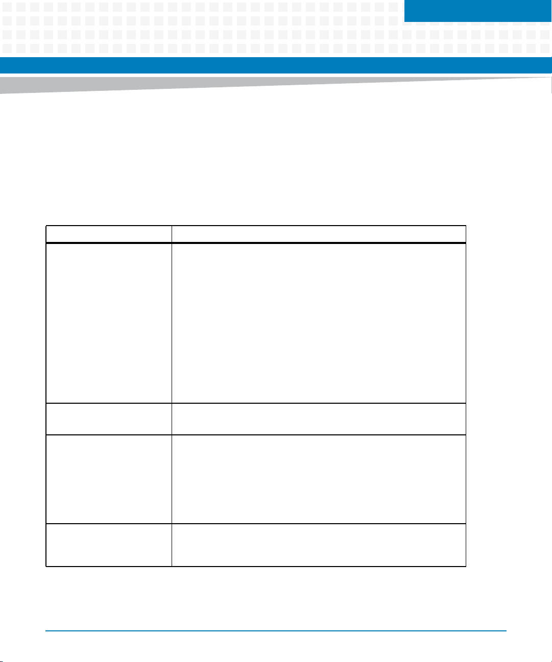
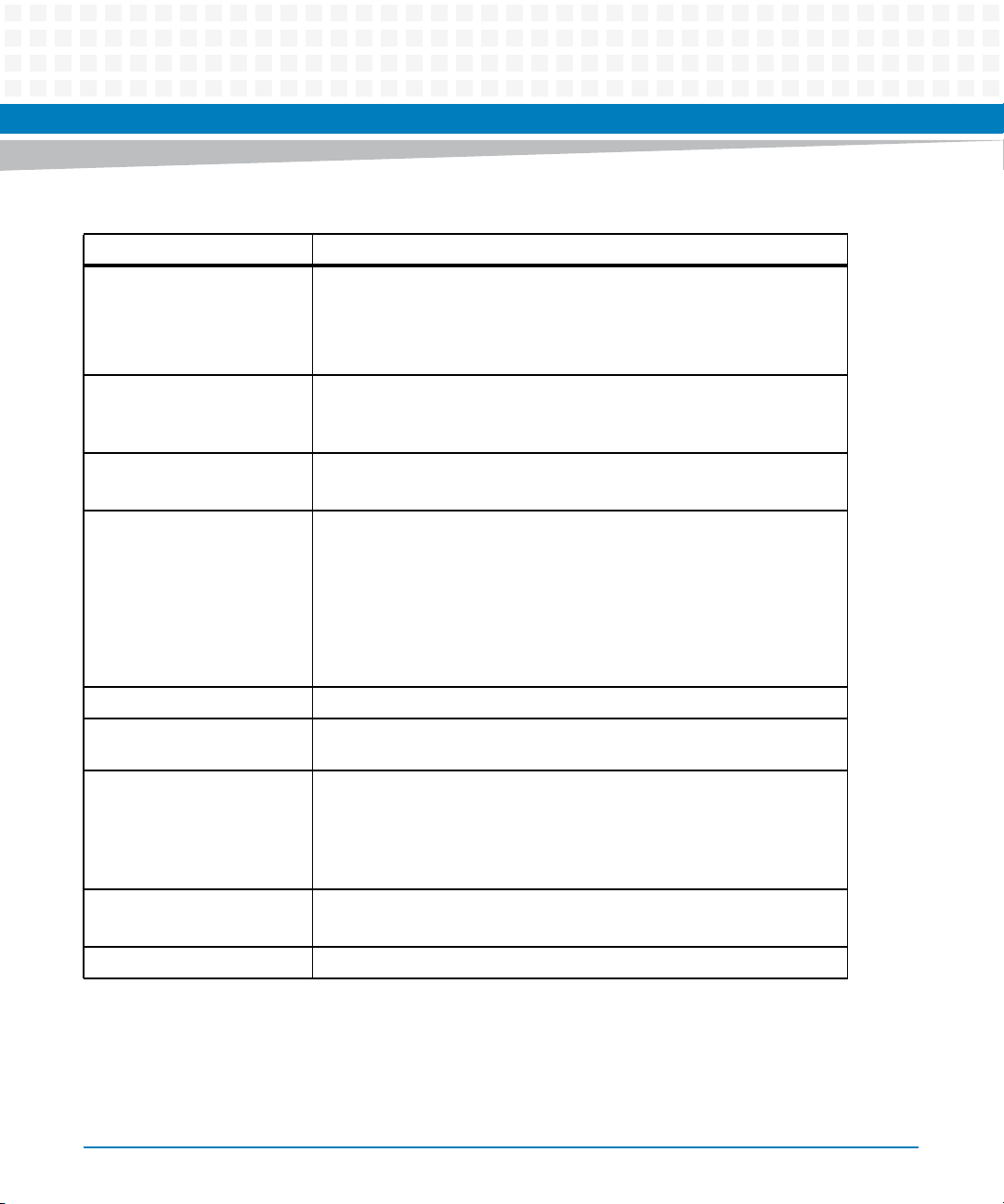
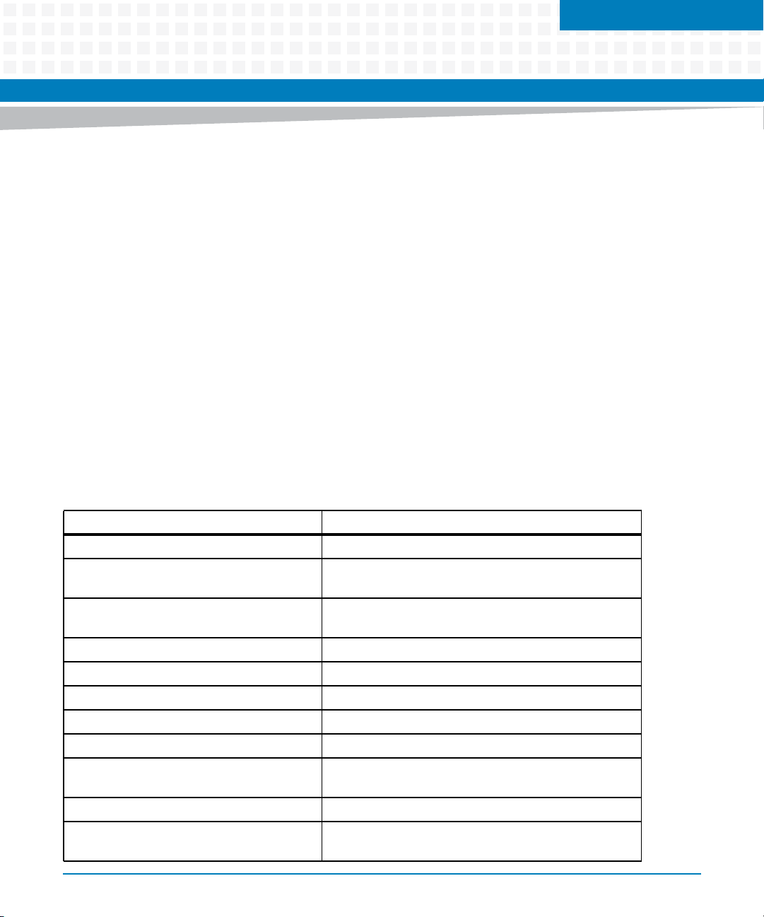
Conventions
The following table describes the conventions used throughout this manual.
Notation Description
0x00000000 Typical notation for hexadecimal numbers (digits are
0b0000 Same for binary numbers (digits are 0 and 1)
bold Used to emphasize a word
Screen Used for on-screen output and code related elements
Courier + Bold Used to characterize user input and to separate it
Reference Used for references and for table and figure
About this Manual
0 through F), for example used for addresses and
offsets
or commands in body text
from system output
descriptions
16
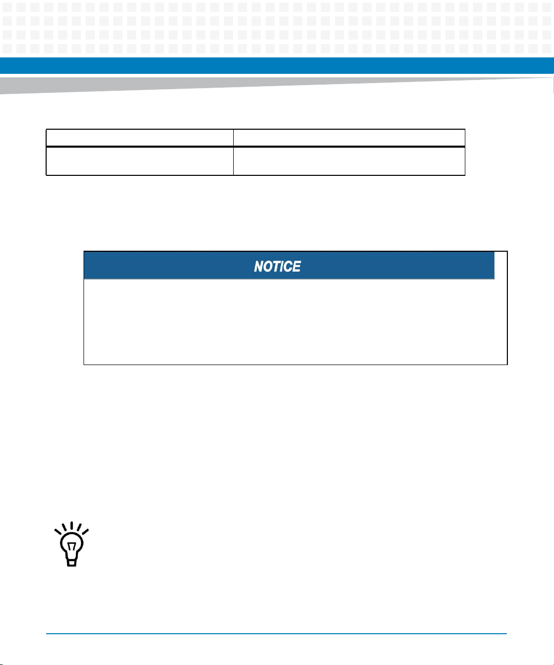
File > Exit Notation for selecting a submenu
<text> Notation for variables and keys
[text] Notation for software buttons to click on the screen
and parameter description
... Repeated item for example node 1, node 2, ..., node
12
.
.
.
.. Ranges, for example: 0..4 means one of the integers
| Logical OR
MVME7100 Single Board Computer Installation and Use (6806800E08D)
Omission of information from example/command
that is not necessary at the time being
0,1,2,3, and 4 (used in registers)
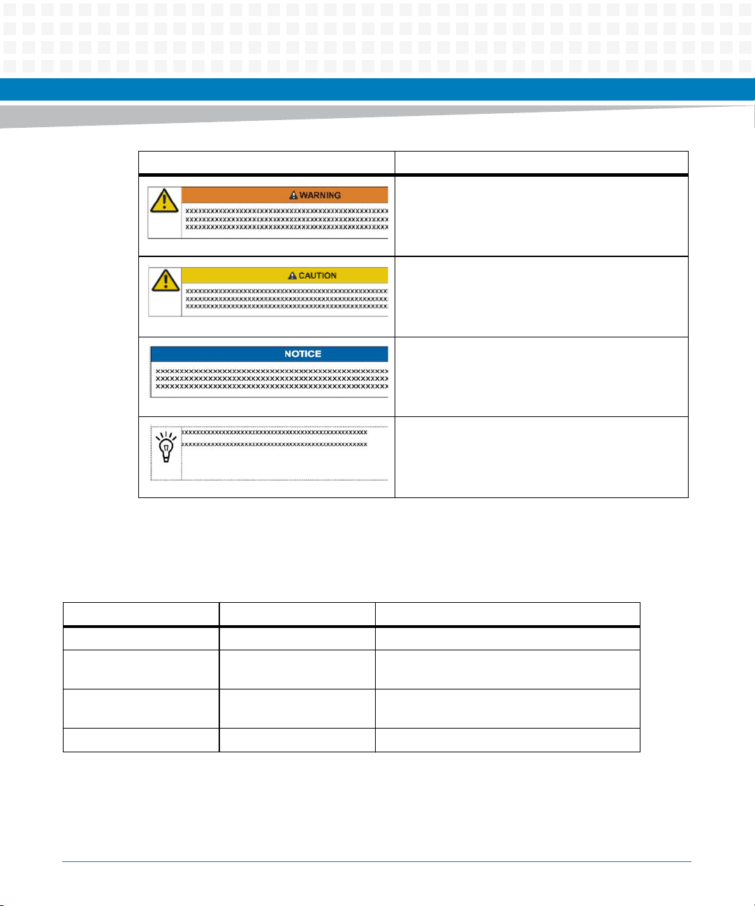
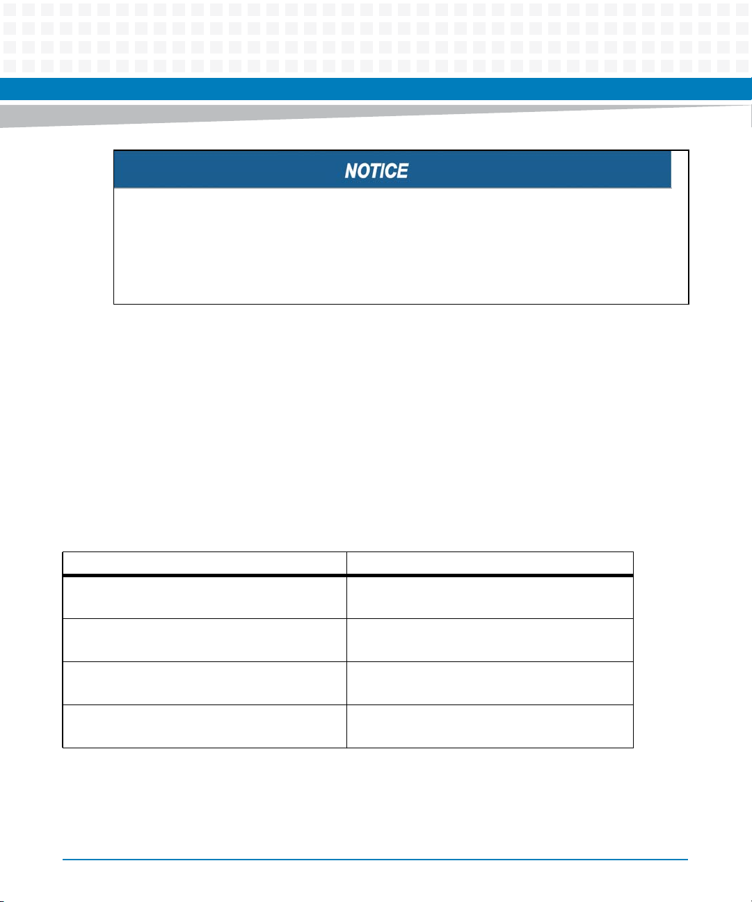
Notation Description
Indicates a hazardous situation which, if not avoided,
could result in death or serious injury
Indicates a hazardous situation which, if not avoided,
may result in minor or moderate injury
Indicates a property damage message
No danger encountered. Pay attention to important
information
About this Manual
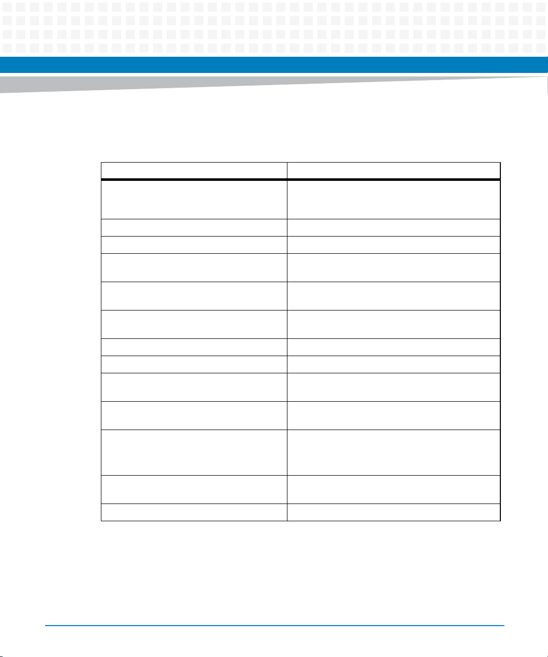
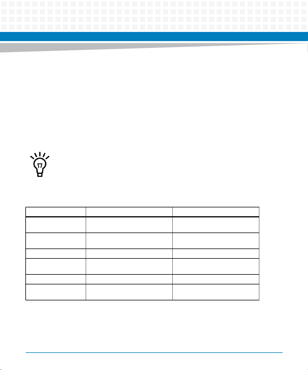
Summary of Changes
This is the first edition of the MVME7100 Single Board Computer Installation and Use.
Part Number Publication Date Description
6806800E08A November 2008 First edition
6806800E08B May 2010 Updated Section 3.3.3 "Connectors" and
Section 5.5 "Rear Panel Connectors"
6806800E08C August 2011 Updated Safety Notes on page 127 and
Sicherheitshinweise on page 131
6806800E08D June 2014 Re- branded to Artesyn template.
MVME7100 Single Board Computer Installation and Use (6806800E08D)
17

About this Manual
About this Manual
18
MVME7100 Single Board Computer Installation and Use (6806800E08D)
Introduction
1.1 Features
The MVME7100 Single Board Computer is a VMEbus board based on the MC8640D and
MC8641D integrated PowerPC processors. It is a full 6U board and occupies a single VME card
slot with PMC cards installed. The MVME7100 is compliant with the VITA standards VMEbus,
2eSST, and PCI-X as listed in Related Documentation on page 121.
Table 1-1 Features List
Function Features
Chapter 1
Processor / Host Controller /
Memory Controller
System Memory Two banks of DDR2 SDRAM with ECC
2
C One 8 KB VPD serial EEPROM
I
NOR Flash 128 MB soldered flash with two alternate 1 MB boot sectors selectable via
One MC864xD Integrated Processor
Two e600 cores with integrated L2
Core frequency of 1.067 or 1.33 GHz
One integrated four channel DMA controller
Two integrated PCIE interfaces
Four integrated 10/100/1000 Ethernet controllers
One integrated DUART
Two integrated I
One integrated Programmable Interrupt Controller
One integrated Local Bus Controller
Two integrated DDR2 SDRAM controllers
1GB, 2 GB, or 4 GB
Two 64 KB user configuration serial EEPROMs
One Real Time Clock (RTC) with removable battery
Dual temperature sensor
Two SPDs for memory
Connection to XMCspan and rear transition module
hardware switch
H/W switch or S/W bit write protection for entire logical bank
2
C controllers
MVME7100 Single Board Computer Installation and Use (6806800E08D)
19
Introduction
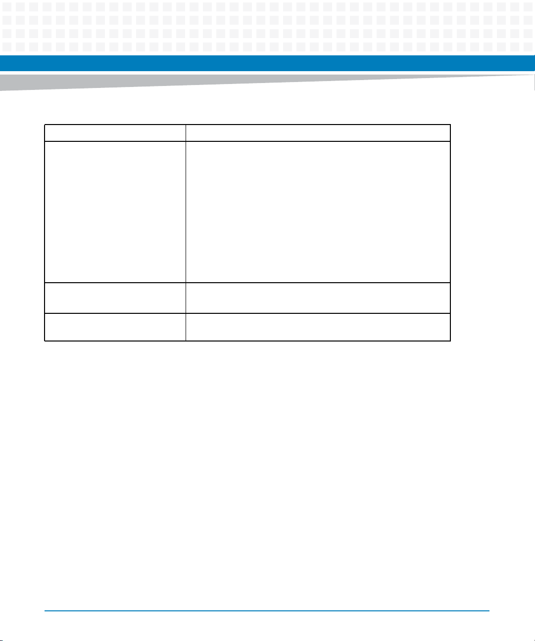
Table 1-1 Features List (continued)
Function Features
NAND Flash Up to two devices available:
4 GB - 1 device
8 GB - 1 device
16 GB - 2 devices
NVRAM One 512 KB MRAM extended temperature range (-40°C to
105°C/-40°F to 221°F)
Two 64 KB serial EEPROMs
PCI_E 8X Port to XMC Expansion
8X Port to 5 Port PCI Express switch
I/O One front panel mini DB-9 connector for front I/O: one serial channel
Two front panel RJ-45 connectors with integrated LEDs for front I/O: two
10/100/1000 Ethernet channels
One front panel USB Type A upright receptacle for front I/O: one USB 2.0
channel
PMC site 1 front I/O and rear P2 I/O
PMC site 2 front I/O
USB One four-channel USB 2.0 controller: one channel for front panel I/O
Ethernet Four 10/100/1000 MC864xD Ethernet channels: two front panel Ethernet
connectors and two channels for rear P2 I/O
Serial Interface One 16550-compatible, 9.6 to 115.2 Kbaud, MC864xD, asynchronous
serial channel: one channel for front panel I/O
One quad UART (QUART) controller to provide four 16550-compatible,
9.6 to 115.2 Kbaud, asynchronous serial channels: four channels for rear
P2 I/O
Timers Four 32-bit MC864xD timers
Four 32-bit timers in a PLD
Watchdog Timer One watchdog timer in PLD
20
MVME7100 Single Board Computer Installation and Use (6806800E08D)
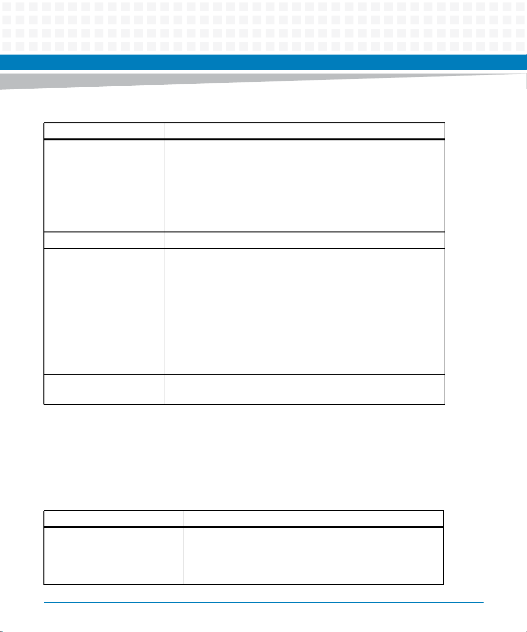
Table 1-1 Features List (continued)
Function Features
VME Interface VME64 (ANSI/VITA 1-1994) compliant (3 row backplane 96-pin VME
connector)
VME64 Extensions (ANSI/VITA 1.1-1997) compliant (5 row backplane
160-pin VME connector)
2eSST (ANSI/VITA 1.5-2003) compliant
Two five-row P1 and P2 backplane connectors
One Tsi148 VMEbus controller
Form Factor Standard 6U VME, one slot
Miscellaneous One front panel RESET/ABORT switch
Six front panel status indicators:
Two 10/100/1000 Ethernet link/speed and activity (4 total)
Board fail
User S/W controlled LED
Planar status indicators
One standard 16-pin JTAG/COP header
Boundary scan support
Switches for VME geographical addressing in a three-row backplane
Introduction
Software Support VxWorks OS support
Linux OS support
1.2 Standard Compliances
The MVME7100 is designed to be CE compliant and to meet the following standard
requirements.
Table 1-2 Board Standard Compliances
Standard Description
UL 60950-1
EN 60950-1
IEC 60950-1
CAN/CSA C22.2 No 60950-1
MVME7100 Single Board Computer Installation and Use (6806800E08D)
Safety Requirements (legal)
21
Introduction
Table 1-2 Board Standard Compliances (continued)
Standard Description
CISPR 22
CISPR 24
EN 55022
EN 55024
FCC Part 15
Industry Canada ICES-003
VCCI Japan
AS/NZS CISPR 22
EN 300 386
NEBS Standard GR-1089 CORE
EMC requirements (legal) on system level (predefined Artesyn
system)
NEBS Standard GR-63-CORE
ETSI EN 300 019 series
Directive 2002/95/EC Directive on the restriction of the use of certain hazardous
Environmental Requirements
substances in electrical and electronic equipment (RoHS)
22
MVME7100 Single Board Computer Installation and Use (6806800E08D)
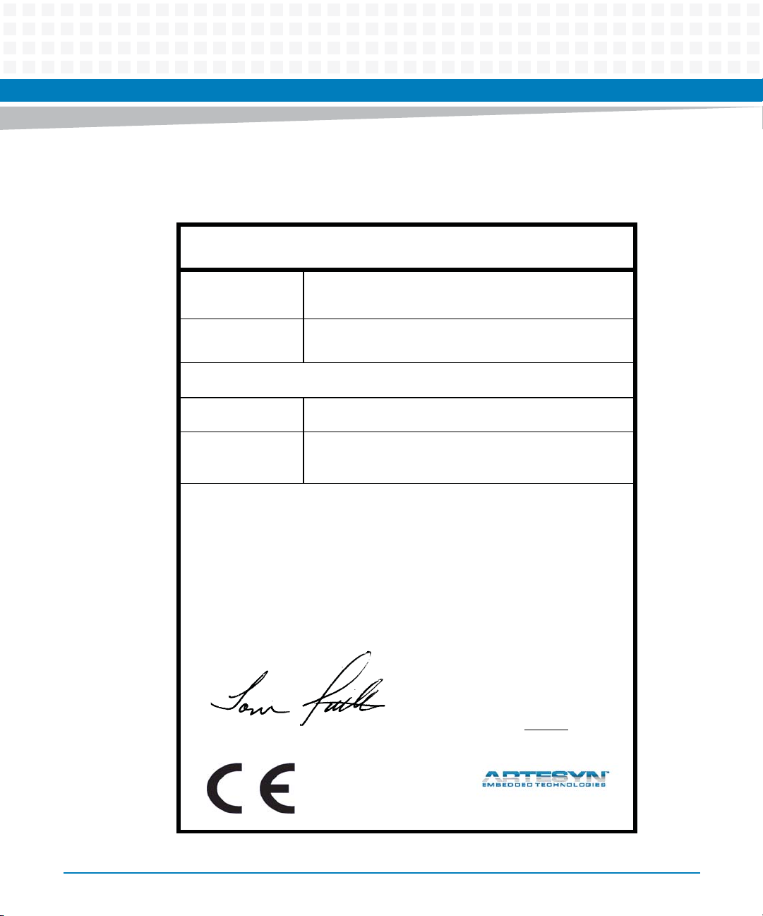
Figure 1-1 Declaration of Conformity
E
C Declaration of Conformity
According to EN 17050-1:2004
Introduction
Manufacturer’s Name:
Manufacturer’s Address:
Declares that the following product, in accordance with the requirements of 2004/108/EC, 2006/95/EC, 2011/65/
EU and their amending directives,
Product:
Model Name/Number:
has been designed and manufactured to the following specifications:
EN55022: 2006
EN55024 (A1: 2001 + A2: 2003): 1998
2011/65/EU RoHS Directive
As manufacturer we hereby declare that the product named above has been designed to comply with the relevant sections of the above referenced specifications. This product complies with the essential health and safety
requirements of the above specified directives. We have an internal production control system that ensures
compliance between the manufactured products and the technical documentation.
Artesyn Embedded Technologies
Embedded Computing
Zhongshan General Carton Box Factory Co. Ltd. No 62, Qi
Guan Road West, Shiqi District, 528400 Zhongshan City
Guangdong, PRC
MVME7100 VMEbus Single Board Computer Series
MVME7100-0161, MVME7100-0163, MVME7100-0171,
MVME7100-0173
___________________________________________________ ___
Tom Tuttle, Manager, Product Testing Services Date (MM/DD/YYYY)
MVME7100 Single Board Computer Installation and Use (6806800E08D)
06/17/2014______
23
Introduction
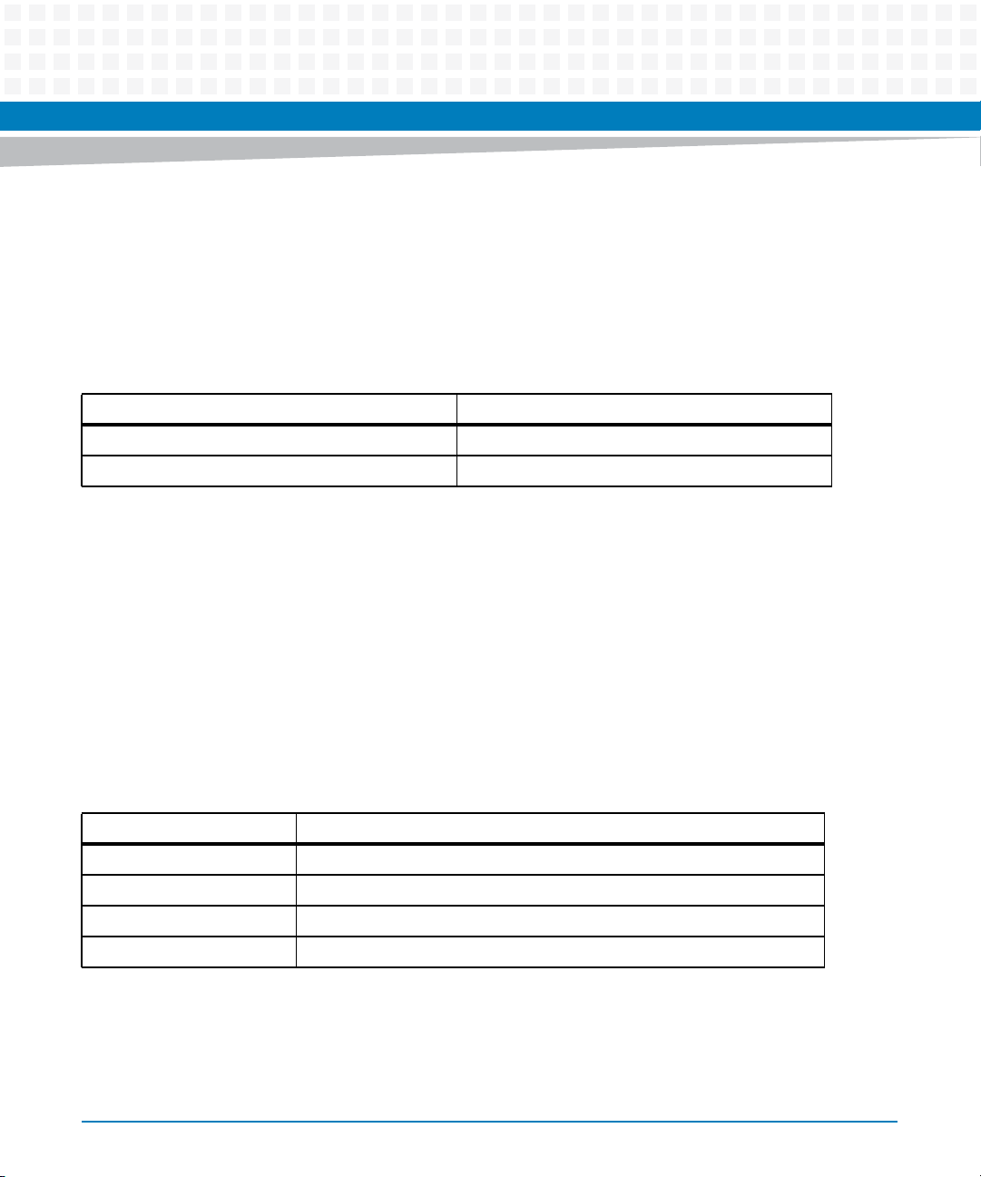
1.3 Mechanical Data
This section provides details on the board’s mechanical data.
Table 1-3 Mechanical Data
Characteristic Value
Dimensions (D x W x H) 6U, 4HP wide, (233 mm x 160 mm x 20 mm)
Weight 0.680 kg
1.4 Ordering Information
When ordering board variants or board accessories, use the order numbers given in the
following tables.
1.4.1 Supported Board Models
At the time of publication of this manual, the MVME7100 Single Board Computer is available in
the configurations shown below.
Table 1-4 Board Variants
Marketing # Processor
MVME7100-0161 MC8640D 1.067 GHz, 1 GB DDR, 4 GB NAND Flash, Scanbe handles
MVME7100-0163 MC8640D 1.067 GHz, 1 GB DDR, 4 GB NAND Flash, IEEE handles
MVME7100-0171 MC8641D 1.33 GHz, 2 GB DDR, 8 GB NAND Flash, Scanbe handles
MVME7100-0173 MC8641D 1.33 GHz, 2 GB DDR, 8 GB NAND Flash, IEEE handles
24
MVME7100 Single Board Computer Installation and Use (6806800E08D)
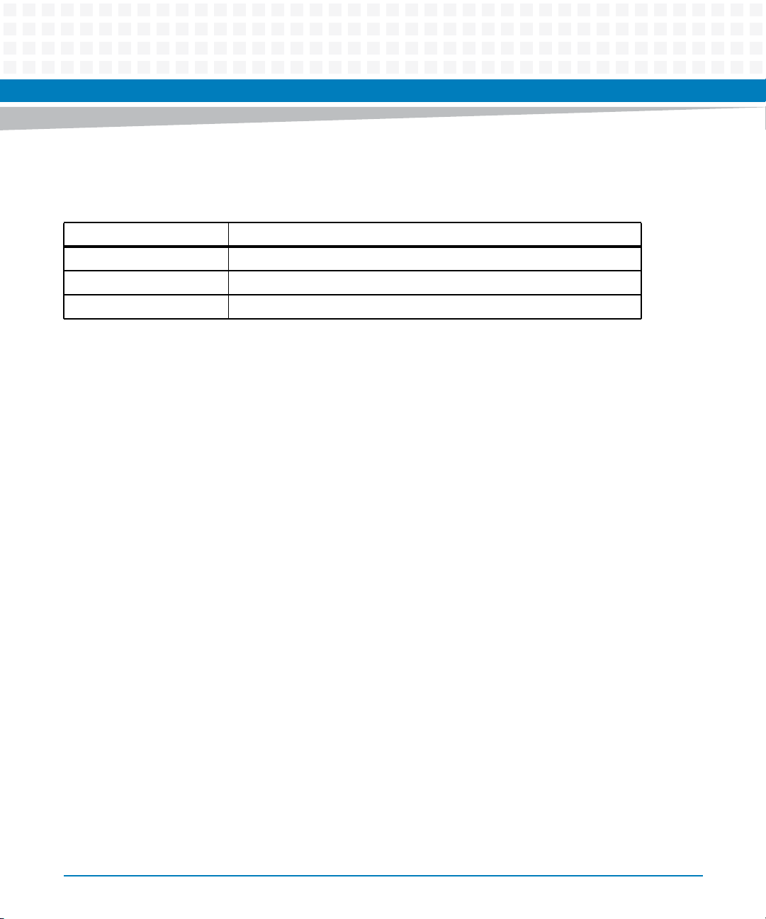
1.4.2 Board Accessories
This table lists the available expansion and transition modules for the MVME7100.
Model Number Description
MVME7216E-001 Transition module, 6E
XMCSPAN-001 XMC Expansion, IEEE handles
XMCSPAN-002 XMC Expansion, Scanbe handles
The IPMC712 and IPMC761 I/O modules are not supported on the MVME7100 SBC.
Introduction
MVME7100 Single Board Computer Installation and Use (6806800E08D)
25

Introduction
26
MVME7100 Single Board Computer Installation and Use (6806800E08D)
Hardware Preparation and Installation
2.1 Overview
This chapter provides startup and safety instructions related to this product, hardware
preparation instruction that includes default switch settings. System considerations and
installation instructions for the baseboard, PMC, and transition module are also described in
this chapter.
A fully implemented MVME7100 consists of the baseboard plus:
Two single-wide or one double-wide PCI Mezzanine Card (PMC) slot for added versatility.
One transition module for support of the mapped I/O from the MVME7100 baseboard to
the P2 connector.
Up to two optional XMCspan cards.
The following table lists the things you will need to do before you can use this board and tells
you where to find the information you need to perform each step. Be sure to read this entire
chapter, including all Caution and Warning notes, before you begin.
Chapter 2
Table 2-1 Startup Overview
Task Page
Unpack the hardware. Unpacking and Inspecting the Board on page 28
Configure the hardware by setting jumpers
on the board and RTM.
Install the MVME7216E transition module in
the chassis.
Install PMC module (if required). Installing Accessories on page 41
Install XMCspan module (if required). XMCspan Installation and Use (6806800H03)
Install the MVME7100 in the chassis. Installing and Removing the Board on page 46
Attach cabling and apply power. Completing the Installation on page 47
Install PIM on transition module (if required). PMC Input/Output Module on page 91
Ensure that the firmware initializes the
MVME7100
Initialize the board Chapter 6, MOTLoad Firmware
Examine and/or change environmental
parameters.
MVME7100 Single Board Computer Installation and Use (6806800E08D)
Configuring the Board on page 35 and SEEPROM Address
Switch, S1 on page 86
Transition Module on page 42
Chapter 6, MOTLoad Firmware
MVME7100 Single Board Computer Programmer’s Reference
27
Hardware Preparation and Installation
Table 2-1 Startup Overview (continued)
Task Page
Program the board as needed for your
applications.
MVME7100 Single Board Computer Programmer’s Reference
2.2 Unpacking and Inspecting the Board
Read all notices and cautions prior to unpacking the product.
Damage of Circuits
Electrostatic discharge and incorrect installation and removal can damage circuits or shorten
their life.
Before touching the board or electronic components, make sure that you are working in an ESDsafe environment.
28
Shipment Inspection
To inspect the shipment, perform the following steps:
1. Verify that you have received all items of your shipment.
2. Check for damage and report any damage or differences to customer service.
3. Remove the desiccant bag shipped together with the board and dispose of it
according to your country’s legislation.
The product is thoroughly inspected before shipment. If any damage occurred during
transportation or any items are missing, contact customer service immediately.
MVME7100 Single Board Computer Installation and Use (6806800E08D)
2.3 Requirements
Make sure that the board, when operated in your particular system configuration, meets the
requirements specified in the next sections.
2.3.1 Environmental Requirements
The following table lists the currently available specifications for the environmental
characteristics of the MVME7100. A complete functional description of the MVME7100
baseboard appears in Chapter 4, Functional Description.
Operating temperatures refer to the temperature of the air circulating around the board and not
to the component temperature.
Hardware Preparation and Installation
Table 2-2 MVME7100 Specifications
Characteristics Operating Nonoperating
Operating temperature 0°C to +55°C (32°F to 131°F) entry air
with forced-air cooling
Temperature change +/-0.5° C/min according to NEBS
Standard GR-63-CORE
Relative humidity 5% to 90% noncondensing 5% to 90% noncondesning
Vibration 1 G sine sweep, 5-100 Hz, horizontal
Shock 20 G peak (half sine) 11mSec
Free Fall 100 mm (unpackaged) per GR-63-
MVME7100 Single Board Computer Installation and Use (6806800E08D)
–40°C to +85° C (-40°F to 185°F)
and vertical (NEBS1)
CORE
29
Hardware Preparation and Installation
Product Damage
High humidity and condensation on the board surface causes short circuits.
Do not operate the board outside the specified environmental limits.
Make sure the board is completely dry and there is no moisture on any surface before applying
power.
2.3.2 Power Requirements
The MVME7100 uses only +5.0 V from the VMEbus backplane. On board power supplies
generate the required voltages for the various ICs. The MVME 7100 connects the +12 V and 12 V supplies from the backplane to the PMC sites while the +3.3 V power supplied to the PMC
sites comes from the +5.0 V backplane power. A maximum of 10 A of +3.3 V power is available
to the PMC sites, however the 90 W +5.0 V limit must be observed as well as any cooling
limitations.
The next table provides an estimate of the typical and maximum power required.
Table 2-3 Power Requirements
Board Variant Power
MVME7100-0161 Typical: 40 W @ +5 V
Maximum: 55 W @ +5 V
MVME7100-0163 Typical: 40 W @ +5 V
Maximum: 55 W @ +5 V
MVME7100-0171 Typical: 45 W @ +5 V
Maximum: 60 W @ +5 V
MVME7100-0173 Typical: 45 W @ +5 V
Maximum: 60 W @ +5 V
30
MVME7100 Single Board Computer Installation and Use (6806800E08D)
 Loading...