

Artesyn MVME2500 ECC Installation

MVME2500-ECC
Installation and Use
P/N: 6806800N30F
August 2014

©
Copyright 2014 Artesyn Embedded Technologies, Inc.
All rights reserved.
Trademarks
Artesyn Embedded Technologies, Artesyn and the Artesyn Embedded Technologies logo are trademarks and service marks of
Artesyn Embedded Technologies, Inc.© 2014 Artesyn Embedded Technologies, Inc. All other product or service names are the
property of their respective owners.
Intel® is a trademark or registered trademark of Intel Corporation or its subsidiaries in the United States and other countries.
Java™ and all other Java-based marks are trademarks or registered trademarks of Oracle America, Inc. in the U.S. and other countries.
Microsoft®, Windows® and Windows Me® are registered trademarks of Microsoft Corporation; and Windows XP™ is a trademark of
Microsoft Corporation.
PICMG®, CompactPCI®, AdvancedTCA™ and the PICMG, CompactPCI and AdvancedTCA logos are registered trademarks of the PCI
Industrial Computer Manufacturers Group.
UNIX® is a registered trademark of The Open Group in the United States and other countries.
Notice
While reasonable efforts have been made to assure the accuracy of this document, Artesyn assumes no liability resulting from any
omissions in this document, or from the use of the information obtained therein. Artesyn reserves the right to revise this document
and to make changes from time to time in the content hereof without obligation of Artesyn to notify any person of such revision or
changes.
Electronic versions of this material may be read online, downloaded for personal use, or referenced in another document as a URL to
an Artesyn website. The text itself may not be published commercially in print or electronic form, edited, translated, or otherwise
altered without the permission of Artesyn.
It is possible that this publication may contain reference to or information about Artesyn products (machines and programs),
programming, or services that are not available in your country. Such references or information must not be construed to mean that
Artesyn intends to announce such Artesyn products, programming, or services in your country.
Limited and Restricted Rights Legend
If the documentation contained herein is supplied, directly or indirectly, to the U.S. Government, the following notice shall apply
unless otherwise agreed to in writing by Artesyn.
Use, duplication, or disclosure by the Government is subject to restrictions as set forth in subparagraph (b)(3) of the Rights in
Technical Data clause at DFARS 252.227-7013 (Nov. 1995) and of the Rights in Noncommercial Computer Software and
Documentation clause at DFARS 252.227-7014 (Jun. 1995).
Contact Address
Artesyn Embedded Technologies Artesyn Embedded Technologies
Marketing Communications
2900 S. Diablo Way, Suite 190
Tempe, Arizona 85282
Lilienthalstr. 17-19
85579 Neubiberg/Munich
Germany

Contents
Contents
About this Manual . . . . . . . . . . . . . . . . . . . . . . . . . . . . . . . . . . . . . . . . . . . . . . . . . . . . . . . . . . . . . . . . . . . . . . . 13
1 Introduction . . . . . . . . . . . . . . . . . . . . . . . . . . . . . . . . . . . . . . . . . . . . . . . . . . . . . . . . . . . . . . . . . . . . . . . . . 19
1.1 Overview . . . . . . . . . . . . . . . . . . . . . . . . . . . . . . . . . . . . . . . . . . . . . . . . . . . . . . . . . . . . . . . . . . . . . . . . . . 19
1.2 Standard Compliances . . . . . . . . . . . . . . . . . . . . . . . . . . . . . . . . . . . . . . . . . . . . . . . . . . . . . . . . . . . . . . 22
1.3 Mechanical Data . . . . . . . . . . . . . . . . . . . . . . . . . . . . . . . . . . . . . . . . . . . . . . . . . . . . . . . . . . . . . . . . . . . 25
1.4 Ordering Information . . . . . . . . . . . . . . . . . . . . . . . . . . . . . . . . . . . . . . . . . . . . . . . . . . . . . . . . . . . . . . . 25
1.5 Product Identification . . . . . . . . . . . . . . . . . . . . . . . . . . . . . . . . . . . . . . . . . . . . . . . . . . . . . . . . . . . . . . . 27
2 Hardware Preparation and Installation . . . . . . . . . . . . . . . . . . . . . . . . . . . . . . . . . . . . . . . . . . . . . . . . . 29
2.1 Overview . . . . . . . . . . . . . . . . . . . . . . . . . . . . . . . . . . . . . . . . . . . . . . . . . . . . . . . . . . . . . . . . . . . . . . . . . . 29
2.2 Unpacking and Inspecting the Board . . . . . . . . . . . . . . . . . . . . . . . . . . . . . . . . . . . . . . . . . . . . . . . . . . 30
2.3 Requirements . . . . . . . . . . . . . . . . . . . . . . . . . . . . . . . . . . . . . . . . . . . . . . . . . . . . . . . . . . . . . . . . . . . . . . 30
2.3.1 Environmental Requirements. . . . . . . . . . . . . . . . . . . . . . . . . . . . . . . . . . . . . . . . . . . . . . . . . . 31
2.3.2 Power Requirements . . . . . . . . . . . . . . . . . . . . . . . . . . . . . . . . . . . . . . . . . . . . . . . . . . . . . . . . . 32
2.3.3 Equipment Requirements . . . . . . . . . . . . . . . . . . . . . . . . . . . . . . . . . . . . . . . . . . . . . . . . . . . . . 34
2.4 Configuring the Board . . . . . . . . . . . . . . . . . . . . . . . . . . . . . . . . . . . . . . . . . . . . . . . . . . . . . . . . . . . . . . 34
2.5 Installing Accessories . . . . . . . . . . . . . . . . . . . . . . . . . . . . . . . . . . . . . . . . . . . . . . . . . . . . . . . . . . . . . . . 35
2.5.1 Rear Transition Module . . . . . . . . . . . . . . . . . . . . . . . . . . . . . . . . . . . . . . . . . . . . . . . . . . . . . . . 35
2.5.2 PMC/XMC Support . . . . . . . . . . . . . . . . . . . . . . . . . . . . . . . . . . . . . . . . . . . . . . . . . . . . . . . . . . . 36
2.6 Installing and Removing the Board . . . . . . . . . . . . . . . . . . . . . . . . . . . . . . . . . . . . . . . . . . . . . . . . . . . . 37
2.7 Completing the Installation . . . . . . . . . . . . . . . . . . . . . . . . . . . . . . . . . . . . . . . . . . . . . . . . . . . . . . . . . . 39
3 Controls, LEDs, and Connectors . . . . . . . . . . . . . . . . . . . . . . . . . . . . . . . . . . . . . . . . . . . . . . . . . . . . . . . . 41
3.1 Board Layout . . . . . . . . . . . . . . . . . . . . . . . . . . . . . . . . . . . . . . . . . . . . . . . . . . . . . . . . . . . . . . . . . . . . . . . 41
3.2 Front Panel . . . . . . . . . . . . . . . . . . . . . . . . . . . . . . . . . . . . . . . . . . . . . . . . . . . . . . . . . . . . . . . . . . . . . . . . 42
3.2.1 Reset Switch. . . . . . . . . . . . . . . . . . . . . . . . . . . . . . . . . . . . . . . . . . . . . . . . . . . . . . . . . . . . . . . . . 43
3.3 LEDs . . . . . . . . . . . . . . . . . . . . . . . . . . . . . . . . . . . . . . . . . . . . . . . . . . . . . . . . . . . . . . . . . . . . . . . . . . . . . . 43
3.3.1 Front Panel LEDs . . . . . . . . . . . . . . . . . . . . . . . . . . . . . . . . . . . . . . . . . . . . . . . . . . . . . . . . . . . . . 43
3.3.2 Onboard LEDs . . . . . . . . . . . . . . . . . . . . . . . . . . . . . . . . . . . . . . . . . . . . . . . . . . . . . . . . . . . . . . . 45
3.4 Connectors . . . . . . . . . . . . . . . . . . . . . . . . . . . . . . . . . . . . . . . . . . . . . . . . . . . . . . . . . . . . . . . . . . . . . . . . 45
3.4.1 Front Panel Connectors . . . . . . . . . . . . . . . . . . . . . . . . . . . . . . . . . . . . . . . . . . . . . . . . . . . . . . . 46
3.4.1.1 RJ45 with Integrated Magnetics (J1) . . . . . . . . . . . . . . . . . . . . . . . . . . . . . . . . . . . 46
3.4.1.2 Front Panel Serial Port (J4) . . . . . . . . . . . . . . . . . . . . . . . . . . . . . . . . . . . . . . . . . . . 47
MVME2500-ECC Installation and Use (6806800N30F)
3

Contents
Contents
Contents
3.4.1.3 USB Connector (J5) . . . . . . . . . . . . . . . . . . . . . . . . . . . . . . . . . . . . . . . . . . . . . . . . . . 48
3.4.1.4 VMEbus P1 Connector . . . . . . . . . . . . . . . . . . . . . . . . . . . . . . . . . . . . . . . . . . . . . . . 48
3.4.1.5 VMEbus P2 Connector . . . . . . . . . . . . . . . . . . . . . . . . . . . . . . . . . . . . . . . . . . . . . . . 50
3.4.2 Onboard Connectors . . . . . . . . . . . . . . . . . . . . . . . . . . . . . . . . . . . . . . . . . . . . . . . . . . . . . . . . . 51
3.4.2.1 Flash Program Connector (P7) . . . . . . . . . . . . . . . . . . . . . . . . . . . . . . . . . . . . . . . . 51
3.4.2.2 SATA Connector (J3) . . . . . . . . . . . . . . . . . . . . . . . . . . . . . . . . . . . . . . . . . . . . . . . . 52
3.4.2.3 PMC Connectors . . . . . . . . . . . . . . . . . . . . . . . . . . . . . . . . . . . . . . . . . . . . . . . . . . . . 53
3.4.2.4 JTAG Connector (P6) . . . . . . . . . . . . . . . . . . . . . . . . . . . . . . . . . . . . . . . . . . . . . . . . 58
3.4.2.5 COP Connector (P6) . . . . . . . . . . . . . . . . . . . . . . . . . . . . . . . . . . . . . . . . . . . . . . . . . 60
3.4.2.6 SD Connector (J2) . . . . . . . . . . . . . . . . . . . . . . . . . . . . . . . . . . . . . . . . . . . . . . . . . . . 60
3.4.2.7 XMC Connector (XJ2) . . . . . . . . . . . . . . . . . . . . . . . . . . . . . . . . . . . . . . . . . . . . . . . . 61
3.4.2.8 Miscellaneous P2020 Debug Connectors . . . . . . . . . . . . . . . . . . . . . . . . . . . . . . 62
3.5 Switches . . . . . . . . . . . . . . . . . . . . . . . . . . . . . . . . . . . . . . . . . . . . . . . . . . . . . . . . . . . . . . . . . . . . . . . . . . 63
3.5.1 Geographical Address Switch (S1). . . . . . . . . . . . . . . . . . . . . . . . . . . . . . . . . . . . . . . . . . . . . . 63
3.5.2 SMT Configuration Switch (S2). . . . . . . . . . . . . . . . . . . . . . . . . . . . . . . . . . . . . . . . . . . . . . . . . 65
4 Functional Description . . . . . . . . . . . . . . . . . . . . . . . . . . . . . . . . . . . . . . . . . . . . . . . . . . . . . . . . . . . . . . . . 67
4.1 Block Diagram . . . . . . . . . . . . . . . . . . . . . . . . . . . . . . . . . . . . . . . . . . . . . . . . . . . . . . . . . . . . . . . . . . . . . 67
4.2 Chipset . . . . . . . . . . . . . . . . . . . . . . . . . . . . . . . . . . . . . . . . . . . . . . . . . . . . . . . . . . . . . . . . . . . . . . . . . . . . 67
4.2.1 e500 Processor Core. . . . . . . . . . . . . . . . . . . . . . . . . . . . . . . . . . . . . . . . . . . . . . . . . . . . . . . . . . 68
4.2.2 Integrated Memory Controller . . . . . . . . . . . . . . . . . . . . . . . . . . . . . . . . . . . . . . . . . . . . . . . . . 68
4.2.3 PCI Express Interface . . . . . . . . . . . . . . . . . . . . . . . . . . . . . . . . . . . . . . . . . . . . . . . . . . . . . . . . . 69
4.2.4 Local Bus Controller (LBC) . . . . . . . . . . . . . . . . . . . . . . . . . . . . . . . . . . . . . . . . . . . . . . . . . . . . . 69
4.2.5 Secure Digital Hub Controller (SDHC). . . . . . . . . . . . . . . . . . . . . . . . . . . . . . . . . . . . . . . . . . . 69
4.2.6 I2C Interface. . . . . . . . . . . . . . . . . . . . . . . . . . . . . . . . . . . . . . . . . . . . . . . . . . . . . . . . . . . . . . . . . 69
4.2.7 USB Interface . . . . . . . . . . . . . . . . . . . . . . . . . . . . . . . . . . . . . . . . . . . . . . . . . . . . . . . . . . . . . . . . 69
4.2.8 DUART. . . . . . . . . . . . . . . . . . . . . . . . . . . . . . . . . . . . . . . . . . . . . . . . . . . . . . . . . . . . . . . . . . . . . . 70
4.2.9 DMA Controller . . . . . . . . . . . . . . . . . . . . . . . . . . . . . . . . . . . . . . . . . . . . . . . . . . . . . . . . . . . . . . 70
4.2.10 Enhanced Three-Speed Ethernet Controller (eTSEC) . . . . . . . . . . . . . . . . . . . . . . . . . . . . . . 70
4.2.11 General Purpose I/O (GPIO). . . . . . . . . . . . . . . . . . . . . . . . . . . . . . . . . . . . . . . . . . . . . . . . . . . . 70
4.2.12 Security Engine (SEC) 3.1. . . . . . . . . . . . . . . . . . . . . . . . . . . . . . . . . . . . . . . . . . . . . . . . . . . . . . 70
4.2.13 Common On-Chip Processor (COP). . . . . . . . . . . . . . . . . . . . . . . . . . . . . . . . . . . . . . . . . . . . . 71
4.2.14 P20x0 Hardware Configuration Pins . . . . . . . . . . . . . . . . . . . . . . . . . . . . . . . . . . . . . . . . . . . . 71
4.3 System Memory . . . . . . . . . . . . . . . . . . . . . . . . . . . . . . . . . . . . . . . . . . . . . . . . . . . . . . . . . . . . . . . . . . . . 71
4.4 Timers . . . . . . . . . . . . . . . . . . . . . . . . . . . . . . . . . . . . . . . . . . . . . . . . . . . . . . . . . . . . . . . . . . . . . . . . . . . . 71
4
MVME2500-ECC Installation and Use (6806800N30F)

Contents
4.4.1 Real Time Clock . . . . . . . . . . . . . . . . . . . . . . . . . . . . . . . . . . . . . . . . . . . . . . . . . . . . . . . . . . . . . . 71
4.4.2 Internal Timer . . . . . . . . . . . . . . . . . . . . . . . . . . . . . . . . . . . . . . . . . . . . . . . . . . . . . . . . . . . . . . . 72
4.4.3 Watchdog Timer . . . . . . . . . . . . . . . . . . . . . . . . . . . . . . . . . . . . . . . . . . . . . . . . . . . . . . . . . . . . . 72
4.4.4 FPGA Tick Timer . . . . . . . . . . . . . . . . . . . . . . . . . . . . . . . . . . . . . . . . . . . . . . . . . . . . . . . . . . . . . 72
4.5 Ethernet Interfaces . . . . . . . . . . . . . . . . . . . . . . . . . . . . . . . . . . . . . . . . . . . . . . . . . . . . . . . . . . . . . . . . . 72
4.6 SPI Bus Interface . . . . . . . . . . . . . . . . . . . . . . . . . . . . . . . . . . . . . . . . . . . . . . . . . . . . . . . . . . . . . . . . . . . . 73
4.6.1 SPI Flash Memory . . . . . . . . . . . . . . . . . . . . . . . . . . . . . . . . . . . . . . . . . . . . . . . . . . . . . . . . . . . . 73
4.6.2 SPI Flash Programming . . . . . . . . . . . . . . . . . . . . . . . . . . . . . . . . . . . . . . . . . . . . . . . . . . . . . . . 73
4.6.3 Firmware Redundancy . . . . . . . . . . . . . . . . . . . . . . . . . . . . . . . . . . . . . . . . . . . . . . . . . . . . . . . . 74
4.6.4 Crisis Recovery. . . . . . . . . . . . . . . . . . . . . . . . . . . . . . . . . . . . . . . . . . . . . . . . . . . . . . . . . . . . . . . 76
4.7 Front UART Control . . . . . . . . . . . . . . . . . . . . . . . . . . . . . . . . . . . . . . . . . . . . . . . . . . . . . . . . . . . . . . . . . 77
4.8 Rear UART Control . . . . . . . . . . . . . . . . . . . . . . . . . . . . . . . . . . . . . . . . . . . . . . . . . . . . . . . . . . . . . . . . . . 77
4.9 PMC/XMC Sites . . . . . . . . . . . . . . . . . . . . . . . . . . . . . . . . . . . . . . . . . . . . . . . . . . . . . . . . . . . . . . . . . . . . . 77
4.9.1 PMC Add-on Card . . . . . . . . . . . . . . . . . . . . . . . . . . . . . . . . . . . . . . . . . . . . . . . . . . . . . . . . . . . . 78
4.9.2 XMC Add-on Card . . . . . . . . . . . . . . . . . . . . . . . . . . . . . . . . . . . . . . . . . . . . . . . . . . . . . . . . . . . . 78
4.10 SATA Interface . . . . . . . . . . . . . . . . . . . . . . . . . . . . . . . . . . . . . . . . . . . . . . . . . . . . . . . . . . . . . . . . . . . . . 79
4.11 VME Support . . . . . . . . . . . . . . . . . . . . . . . . . . . . . . . . . . . . . . . . . . . . . . . . . . . . . . . . . . . . . . . . . . . . . . . 79
4.11.1 Tsi148 VME Controller . . . . . . . . . . . . . . . . . . . . . . . . . . . . . . . . . . . . . . . . . . . . . . . . . . . . . . . . 79
4.12 USB . . . . . . . . . . . . . . . . . . . . . . . . . . . . . . . . . . . . . . . . . . . . . . . . . . . . . . . . . . . . . . . . . . . . . . . . . . . . . . . 79
4.13 I2C Devices . . . . . . . . . . . . . . . . . . . . . . . . . . . . . . . . . . . . . . . . . . . . . . . . . . . . . . . . . . . . . . . . . . . . . . . . 80
4.14 Reset/Control FPGA . . . . . . . . . . . . . . . . . . . . . . . . . . . . . . . . . . . . . . . . . . . . . . . . . . . . . . . . . . . . . . . . . 80
4.15 Power Management . . . . . . . . . . . . . . . . . . . . . . . . . . . . . . . . . . . . . . . . . . . . . . . . . . . . . . . . . . . . . . . . 80
4.15.1 Onboard Voltage Supply Requirement. . . . . . . . . . . . . . . . . . . . . . . . . . . . . . . . . . . . . . . . . . 81
4.15.2 Power Up Sequencing Requirements . . . . . . . . . . . . . . . . . . . . . . . . . . . . . . . . . . . . . . . . . . . 81
4.16 Clock Structure . . . . . . . . . . . . . . . . . . . . . . . . . . . . . . . . . . . . . . . . . . . . . . . . . . . . . . . . . . . . . . . . . . . . . 82
4.17 Reset Structure . . . . . . . . . . . . . . . . . . . . . . . . . . . . . . . . . . . . . . . . . . . . . . . . . . . . . . . . . . . . . . . . . . . . . 82
4.17.1 Reset Sequence. . . . . . . . . . . . . . . . . . . . . . . . . . . . . . . . . . . . . . . . . . . . . . . . . . . . . . . . . . . . . . 83
4.18 Thermal Management . . . . . . . . . . . . . . . . . . . . . . . . . . . . . . . . . . . . . . . . . . . . . . . . . . . . . . . . . . . . . . 83
4.19 Real-Time Clock Battery . . . . . . . . . . . . . . . . . . . . . . . . . . . . . . . . . . . . . . . . . . . . . . . . . . . . . . . . . . . . . 84
4.20 Debugging Support . . . . . . . . . . . . . . . . . . . . . . . . . . . . . . . . . . . . . . . . . . . . . . . . . . . . . . . . . . . . . . . . . 84
4.20.1 POST Code Indicator. . . . . . . . . . . . . . . . . . . . . . . . . . . . . . . . . . . . . . . . . . . . . . . . . . . . . . . . . . 84
4.20.2 Custom Debugging . . . . . . . . . . . . . . . . . . . . . . . . . . . . . . . . . . . . . . . . . . . . . . . . . . . . . . . . . . 85
4.21 Rear Transition Module (RTM) . . . . . . . . . . . . . . . . . . . . . . . . . . . . . . . . . . . . . . . . . . . . . . . . . . . . . . . . 85
MVME2500-ECC Installation and Use (6806800N30F)
5

Contents
Contents
Contents
5 Memory Maps and Registers. . . . . . . . . . . . . . . . . . . . . . . . . . . . . . . . . . . . . . . . . . . . . . . . . . . . . . . . . . . 87
5.1 Overview . . . . . . . . . . . . . . . . . . . . . . . . . . . . . . . . . . . . . . . . . . . . . . . . . . . . . . . . . . . . . . . . . . . . . . . . . . 87
5.2 Memory Map . . . . . . . . . . . . . . . . . . . . . . . . . . . . . . . . . . . . . . . . . . . . . . . . . . . . . . . . . . . . . . . . . . . . . . 87
5.3 Linux Devices Memory Map . . . . . . . . . . . . . . . . . . . . . . . . . . . . . . . . . . . . . . . . . . . . . . . . . . . . . . . . . . 88
5.4 Programmable Logic Device (PLD) Registers . . . . . . . . . . . . . . . . . . . . . . . . . . . . . . . . . . . . . . . . . . . 89
5.4.1 PLD Revision Register. . . . . . . . . . . . . . . . . . . . . . . . . . . . . . . . . . . . . . . . . . . . . . . . . . . . . . . . . 89
5.4.2 PLD Year Register . . . . . . . . . . . . . . . . . . . . . . . . . . . . . . . . . . . . . . . . . . . . . . . . . . . . . . . . . . . . 90
5.4.3 PLD Month Register . . . . . . . . . . . . . . . . . . . . . . . . . . . . . . . . . . . . . . . . . . . . . . . . . . . . . . . . . . 90
5.4.4 PLD Day Register. . . . . . . . . . . . . . . . . . . . . . . . . . . . . . . . . . . . . . . . . . . . . . . . . . . . . . . . . . . . . 91
5.4.5 PLD Sequence Register . . . . . . . . . . . . . . . . . . . . . . . . . . . . . . . . . . . . . . . . . . . . . . . . . . . . . . . 91
5.4.6 PLD Power Good Monitor Register . . . . . . . . . . . . . . . . . . . . . . . . . . . . . . . . . . . . . . . . . . . . . 92
5.4.7 PLD LED Control Register. . . . . . . . . . . . . . . . . . . . . . . . . . . . . . . . . . . . . . . . . . . . . . . . . . . . . . 93
5.4.8 PLD PCI/PMC/XMC Monitor Register. . . . . . . . . . . . . . . . . . . . . . . . . . . . . . . . . . . . . . . . . . . . 93
5.4.9 PLD U-Boot and TSI Monitor Register . . . . . . . . . . . . . . . . . . . . . . . . . . . . . . . . . . . . . . . . . . . 94
5.4.10 PLD Boot Bank Register . . . . . . . . . . . . . . . . . . . . . . . . . . . . . . . . . . . . . . . . . . . . . . . . . . . . . . . 95
5.4.11 PLD Write Protect and I2C Debug Register . . . . . . . . . . . . . . . . . . . . . . . . . . . . . . . . . . . . . . 97
5.4.12 PLD Test Register 1 . . . . . . . . . . . . . . . . . . . . . . . . . . . . . . . . . . . . . . . . . . . . . . . . . . . . . . . . . . . 99
5.4.13 PLD Test Register 2 . . . . . . . . . . . . . . . . . . . . . . . . . . . . . . . . . . . . . . . . . . . . . . . . . . . . . . . . . . . 99
5.4.14 PLD GPIO2 Interrupt Register . . . . . . . . . . . . . . . . . . . . . . . . . . . . . . . . . . . . . . . . . . . . . . . . . 100
5.4.15 Reset Control and Reset Reason Register. . . . . . . . . . . . . . . . . . . . . . . . . . . . . . . . . . . . . . . 101
5.4.16 PLD Watchdog Timer Refresh Register. . . . . . . . . . . . . . . . . . . . . . . . . . . . . . . . . . . . . . . . . 102
5.4.17 PLD Watchdog Control Register. . . . . . . . . . . . . . . . . . . . . . . . . . . . . . . . . . . . . . . . . . . . . . . 103
5.4.18 PLD Watchdog Timer Count Register . . . . . . . . . . . . . . . . . . . . . . . . . . . . . . . . . . . . . . . . . . 103
5.5 External Timer Registers . . . . . . . . . . . . . . . . . . . . . . . . . . . . . . . . . . . . . . . . . . . . . . . . . . . . . . . . . . . . 104
5.5.1 Prescaler Register . . . . . . . . . . . . . . . . . . . . . . . . . . . . . . . . . . . . . . . . . . . . . . . . . . . . . . . . . . . 104
5.5.2 Control Registers. . . . . . . . . . . . . . . . . . . . . . . . . . . . . . . . . . . . . . . . . . . . . . . . . . . . . . . . . . . . 105
5.5.3 Compare High and Low Word Registers. . . . . . . . . . . . . . . . . . . . . . . . . . . . . . . . . . . . . . . . 106
5.5.4 Counter High and Low Word Registers. . . . . . . . . . . . . . . . . . . . . . . . . . . . . . . . . . . . . . . . . 107
6 Boot System . . . . . . . . . . . . . . . . . . . . . . . . . . . . . . . . . . . . . . . . . . . . . . . . . . . . . . . . . . . . . . . . . . . . . . . .109
6.1 Overview . . . . . . . . . . . . . . . . . . . . . . . . . . . . . . . . . . . . . . . . . . . . . . . . . . . . . . . . . . . . . . . . . . . . . . . . . 109
6.2 Accessing U-Boot . . . . . . . . . . . . . . . . . . . . . . . . . . . . . . . . . . . . . . . . . . . . . . . . . . . . . . . . . . . . . . . . . . 109
6.3 Boot Options . . . . . . . . . . . . . . . . . . . . . . . . . . . . . . . . . . . . . . . . . . . . . . . . . . . . . . . . . . . . . . . . . . . . . . 110
6.3.1 Booting from a Network . . . . . . . . . . . . . . . . . . . . . . . . . . . . . . . . . . . . . . . . . . . . . . . . . . . . . 110
6.3.2 Booting from an Optional SATA Drive. . . . . . . . . . . . . . . . . . . . . . . . . . . . . . . . . . . . . . . . . . 111
6
MVME2500-ECC Installation and Use (6806800N30F)

Contents
6.3.3 Booting from a USB Drive . . . . . . . . . . . . . . . . . . . . . . . . . . . . . . . . . . . . . . . . . . . . . . . . . . . . 111
6.3.4 Booting from an SD Card. . . . . . . . . . . . . . . . . . . . . . . . . . . . . . . . . . . . . . . . . . . . . . . . . . . . . 112
6.3.5 Booting VxWorks Through the Network. . . . . . . . . . . . . . . . . . . . . . . . . . . . . . . . . . . . . . . . 112
6.4 Using the Persistent Memory Feature . . . . . . . . . . . . . . . . . . . . . . . . . . . . . . . . . . . . . . . . . . . . . . . . 113
6.5 MVME2500-ECC Specific U-Boot Commands . . . . . . . . . . . . . . . . . . . . . . . . . . . . . . . . . . . . . . . . . . 114
6.6 Updating U-Boot . . . . . . . . . . . . . . . . . . . . . . . . . . . . . . . . . . . . . . . . . . . . . . . . . . . . . . . . . . . . . . . . . . 116
7 Programming Model. . . . . . . . . . . . . . . . . . . . . . . . . . . . . . . . . . . . . . . . . . . . . . . . . . . . . . . . . . . . . . . . . 119
7.1 Overview . . . . . . . . . . . . . . . . . . . . . . . . . . . . . . . . . . . . . . . . . . . . . . . . . . . . . . . . . . . . . . . . . . . . . . . . . 119
7.2 Reset Configuration . . . . . . . . . . . . . . . . . . . . . . . . . . . . . . . . . . . . . . . . . . . . . . . . . . . . . . . . . . . . . . . 119
7.3 Interrupt Controller . . . . . . . . . . . . . . . . . . . . . . . . . . . . . . . . . . . . . . . . . . . . . . . . . . . . . . . . . . . . . . . . 123
7.4 I2C Bus Device Addressing . . . . . . . . . . . . . . . . . . . . . . . . . . . . . . . . . . . . . . . . . . . . . . . . . . . . . . . . . . 124
7.5 Ethernet PHY Address . . . . . . . . . . . . . . . . . . . . . . . . . . . . . . . . . . . . . . . . . . . . . . . . . . . . . . . . . . . . . . 124
7.6 Other Software Considerations . . . . . . . . . . . . . . . . . . . . . . . . . . . . . . . . . . . . . . . . . . . . . . . . . . . . . . 125
7.6.1 MRAM . . . . . . . . . . . . . . . . . . . . . . . . . . . . . . . . . . . . . . . . . . . . . . . . . . . . . . . . . . . . . . . . . . . . . 125
7.6.2 Real Time Clock . . . . . . . . . . . . . . . . . . . . . . . . . . . . . . . . . . . . . . . . . . . . . . . . . . . . . . . . . . . . .125
7.6.3 Quad UART. . . . . . . . . . . . . . . . . . . . . . . . . . . . . . . . . . . . . . . . . . . . . . . . . . . . . . . . . . . . . . . . . 125
7.6.4 LBC Timing Parameters . . . . . . . . . . . . . . . . . . . . . . . . . . . . . . . . . . . . . . . . . . . . . . . . . . . . . . 126
7.7 Clock Distribution . . . . . . . . . . . . . . . . . . . . . . . . . . . . . . . . . . . . . . . . . . . . . . . . . . . . . . . . . . . . . . . . .127
7.7.1 System Clock . . . . . . . . . . . . . . . . . . . . . . . . . . . . . . . . . . . . . . . . . . . . . . . . . . . . . . . . . . . . . . . 128
7.7.2 Real Time Clock Input. . . . . . . . . . . . . . . . . . . . . . . . . . . . . . . . . . . . . . . . . . . . . . . . . . . . . . . . 129
7.7.3 Local Bus Controller Clock Divisor . . . . . . . . . . . . . . . . . . . . . . . . . . . . . . . . . . . . . . . . . . . . . 129
A Replacing the Battery . . . . . . . . . . . . . . . . . . . . . . . . . . . . . . . . . . . . . . . . . . . . . . . . . . . . . . . . . . . . . . . . 131
A.1 Replacing the Battery . . . . . . . . . . . . . . . . . . . . . . . . . . . . . . . . . . . . . . . . . . . . . . . . . . . . . . . . . . . . . . 131
B Related Documentation. . . . . . . . . . . . . . . . . . . . . . . . . . . . . . . . . . . . . . . . . . . . . . . . . . . . . . . . . . . . . . 135
B.1 Artesyn Embedded Technologies - Embedded Computing Documentation . . . . . . . . . . . . . . .135
B.2 Manufacturers’ Documents . . . . . . . . . . . . . . . . . . . . . . . . . . . . . . . . . . . . . . . . . . . . . . . . . . . . . . . . . 135
B.3 Related Specifications . . . . . . . . . . . . . . . . . . . . . . . . . . . . . . . . . . . . . . . . . . . . . . . . . . . . . . . . . . . . . . 136
MVME2500-ECC Installation and Use (6806800N30F)
7

Contents
Contents
Contents
Safety Notes . . . . . . . . . . . . . . . . . . . . . . . . . . . . . . . . . . . . . . . . . . . . . . . . . . . . . . . . . . . . . . . . . . . . . . . . . . . .139
Sicherheitshinweise . . . . . . . . . . . . . . . . . . . . . . . . . . . . . . . . . . . . . . . . . . . . . . . . . . . . . . . . . . . . . . . . . . . . . 143
8
MVME2500-ECC Installation and Use (6806800N30F)

List of Tables
Table 1-1 Key Features of the MVME2500-ECC . . . . . . . . . . . . . . . . . . . . . . . . . . . . . . . . . . . . . . . . . . . . . . 19
Table 1-2 Board Standard Compliances . . . . . . . . . . . . . . . . . . . . . . . . . . . . . . . . . . . . . . . . . . . . . . . . . . . . 22
Table 1-3 Mechanical Data . . . . . . . . . . . . . . . . . . . . . . . . . . . . . . . . . . . . . . . . . . . . . . . . . . . . . . . . . . . . . . . 25
Table 1-4 Available Board Variants . . . . . . . . . . . . . . . . . . . . . . . . . . . . . . . . . . . . . . . . . . . . . . . . . . . . . . . . 25
Table 1-5 Available Extended Temperature Variants . . . . . . . . . . . . . . . . . . . . . . . . . . . . . . . . . . . . . . . . . 25
Table 1-6 Available Board Accessories . . . . . . . . . . . . . . . . . . . . . . . . . . . . . . . . . . . . . . . . . . . . . . . . . . . . 26
Table 2-1 Environmental Requirements . . . . . . . . . . . . . . . . . . . . . . . . . . . . . . . . . . . . . . . . . . . . . . . . . . . . 31
Table 2-2 Power Requirements . . . . . . . . . . . . . . . . . . . . . . . . . . . . . . . . . . . . . . . . . . . . . . . . . . . . . . . . . . . 33
Table 3-1 Front Panel LEDs . . . . . . . . . . . . . . . . . . . . . . . . . . . . . . . . . . . . . . . . . . . . . . . . . . . . . . . . . . . . . . . 44
Table 3-2 Onboard LEDs Status . . . . . . . . . . . . . . . . . . . . . . . . . . . . . . . . . . . . . . . . . . . . . . . . . . . . . . . . . . . 45
Table 3-3 Front Panel Tri-Speed Ethernet Connector (J1) . . . . . . . . . . . . . . . . . . . . . . . . . . . . . . . . . . . . . 46
Table 3-4 Front Panel Serial Port (J4) . . . . . . . . . . . . . . . . . . . . . . . . . . . . . . . . . . . . . . . . . . . . . . . . . . . . . . . 47
Table 3-5 USB Connector (J5) . . . . . . . . . . . . . . . . . . . . . . . . . . . . . . . . . . . . . . . . . . . . . . . . . . . . . . . . . . . . . 48
Table 3-6 VMEbus P1 Connector . . . . . . . . . . . . . . . . . . . . . . . . . . . . . . . . . . . . . . . . . . . . . . . . . . . . . . . . . . 48
Table 3-7 VMEbus P2 Connector . . . . . . . . . . . . . . . . . . . . . . . . . . . . . . . . . . . . . . . . . . . . . . . . . . . . . . . . . . 50
Table 3-8 Flash Programming Header (P7) . . . . . . . . . . . . . . . . . . . . . . . . . . . . . . . . . . . . . . . . . . . . . . . . . 51
Table 3-9 Custom SATA Connector (J3) . . . . . . . . . . . . . . . . . . . . . . . . . . . . . . . . . . . . . . . . . . . . . . . . . . . . 52
Table 3-10 PMC J11 Connector . . . . . . . . . . . . . . . . . . . . . . . . . . . . . . . . . . . . . . . . . . . . . . . . . . . . . . . . . . . . 53
Table 3-11 PMC J12 Connector . . . . . . . . . . . . . . . . . . . . . . . . . . . . . . . . . . . . . . . . . . . . . . . . . . . . . . . . . . . . 54
Table 3-12 PMC J13 Connector . . . . . . . . . . . . . . . . . . . . . . . . . . . . . . . . . . . . . . . . . . . . . . . . . . . . . . . . . . . . 55
Table 3-13 PMC J14 Connector . . . . . . . . . . . . . . . . . . . . . . . . . . . . . . . . . . . . . . . . . . . . . . . . . . . . . . . . . . . . 57
Table 3-14 JTAG Connector (P6) . . . . . . . . . . . . . . . . . . . . . . . . . . . . . . . . . . . . . . . . . . . . . . . . . . . . . . . . . . . . 58
Table 3-15 COP Header (P10) . . . . . . . . . . . . . . . . . . . . . . . . . . . . . . . . . . . . . . . . . . . . . . . . . . . . . . . . . . . . . . 60
Table 3-16 SD Connector (J2) . . . . . . . . . . . . . . . . . . . . . . . . . . . . . . . . . . . . . . . . . . . . . . . . . . . . . . . . . . . . . . 60
Table 3-17 XMC Connector (XJ2) Pinout . . . . . . . . . . . . . . . . . . . . . . . . . . . . . . . . . . . . . . . . . . . . . . . . . . . . 61
Table 3-18 P20x0 Debug Header . . . . . . . . . . . . . . . . . . . . . . . . . . . . . . . . . . . . . . . . . . . . . . . . . . . . . . . . . . . 62
Table 3-19 Geographical Address Switch . . . . . . . . . . . . . . . . . . . . . . . . . . . . . . . . . . . . . . . . . . . . . . . . . . . . 64
Table 3-20 Geographical Address Switch Settings . . . . . . . . . . . . . . . . . . . . . . . . . . . . . . . . . . . . . . . . . . . . 65
Table 4-1 Voltage Supply Requirement . . . . . . . . . . . . . . . . . . . . . . . . . . . . . . . . . . . . . . . . . . . . . . . . . . . . 81
Table 4-2 Thermal Interrupt Threshold . . . . . . . . . . . . . . . . . . . . . . . . . . . . . . . . . . . . . . . . . . . . . . . . . . . . . 83
Table 4-3 Real-Time Clock Battery . . . . . . . . . . . . . . . . . . . . . . . . . . . . . . . . . . . . . . . . . . . . . . . . . . . . . . . . . 84
Table 4-4 POST Code Indicator on the LED . . . . . . . . . . . . . . . . . . . . . . . . . . . . . . . . . . . . . . . . . . . . . . . . . 84
Table 4-5 Transition Module Features . . . . . . . . . . . . . . . . . . . . . . . . . . . . . . . . . . . . . . . . . . . . . . . . . . . . . . 86
Table 5-1 Physical Address Map . . . . . . . . . . . . . . . . . . . . . . . . . . . . . . . . . . . . . . . . . . . . . . . . . . . . . . . . . . . 87
Table 5-2 Linux Devices Memory Map . . . . . . . . . . . . . . . . . . . . . . . . . . . . . . . . . . . . . . . . . . . . . . . . . . . . . 88
Table 5-3 PLD Revision Register . . . . . . . . . . . . . . . . . . . . . . . . . . . . . . . . . . . . . . . . . . . . . . . . . . . . . . . . . . . 89
MVME2500-ECC Installation and Use (6806800N30F)
9

List of Tables
Table 5-4 PLD Year Register . . . . . . . . . . . . . . . . . . . . . . . . . . . . . . . . . . . . . . . . . . . . . . . . . . . . . . . . . . . . . . 90
Table 5-5 PLD Month Register . . . . . . . . . . . . . . . . . . . . . . . . . . . . . . . . . . . . . . . . . . . . . . . . . . . . . . . . . . . .90
Table 5-6 PLD Day Register . . . . . . . . . . . . . . . . . . . . . . . . . . . . . . . . . . . . . . . . . . . . . . . . . . . . . . . . . . . . . . . 91
Table 5-7 PLD Sequence Register . . . . . . . . . . . . . . . . . . . . . . . . . . . . . . . . . . . . . . . . . . . . . . . . . . . . . . . . . . 91
Table 5-8 PLD Power Good Monitor Register . . . . . . . . . . . . . . . . . . . . . . . . . . . . . . . . . . . . . . . . . . . . . . . . 92
Table 5-9 PLD LED Control Register . . . . . . . . . . . . . . . . . . . . . . . . . . . . . . . . . . . . . . . . . . . . . . . . . . . . . . . . 93
Table 5-10 PLD PCI/PMC/XMC Monitor Register . . . . . . . . . . . . . . . . . . . . . . . . . . . . . . . . . . . . . . . . . . . . . . 93
Table 5-11 PLD U-Boot and TSI Monitor Register . . . . . . . . . . . . . . . . . . . . . . . . . . . . . . . . . . . . . . . . . . . . . 94
Table 5-12 PLD Boot Bank Register . . . . . . . . . . . . . . . . . . . . . . . . . . . . . . . . . . . . . . . . . . . . . . . . . . . . . . . . . 95
Table 5-13 PLD Write Protect and I2C Debug Register . . . . . . . . . . . . . . . . . . . . . . . . . . . . . . . . . . . . . . . . . 97
Table 5-14 PLD Test Register 1 . . . . . . . . . . . . . . . . . . . . . . . . . . . . . . . . . . . . . . . . . . . . . . . . . . . . . . . . . . . . . 99
Table 5-15 PLD Test Register 2 . . . . . . . . . . . . . . . . . . . . . . . . . . . . . . . . . . . . . . . . . . . . . . . . . . . . . . . . . . . . . 99
Table 5-16 PLD GPIO2 Interrupt Register . . . . . . . . . . . . . . . . . . . . . . . . . . . . . . . . . . . . . . . . . . . . . . . . . . .100
Table 5-17 PLD Shutdown and Reset Control and Reset Reason Register . . . . . . . . . . . . . . . . . . . . . . . .101
Table 5-18 PLD Watchdog Timer Refresh Register . . . . . . . . . . . . . . . . . . . . . . . . . . . . . . . . . . . . . . . . . . .102
Table 5-19 PLD Watchdog Control Register . . . . . . . . . . . . . . . . . . . . . . . . . . . . . . . . . . . . . . . . . . . . . . . . .103
Table 5-20 PLD Watchdog Timer Count Register . . . . . . . . . . . . . . . . . . . . . . . . . . . . . . . . . . . . . . . . . . . .103
Table 5-21 Prescaler Register . . . . . . . . . . . . . . . . . . . . . . . . . . . . . . . . . . . . . . . . . . . . . . . . . . . . . . . . . . . . .104
Table 5-22 Control Registers . . . . . . . . . . . . . . . . . . . . . . . . . . . . . . . . . . . . . . . . . . . . . . . . . . . . . . . . . . . . . .105
Table 5-23 Compare High Word Registers . . . . . . . . . . . . . . . . . . . . . . . . . . . . . . . . . . . . . . . . . . . . . . . . . .106
Table 5-24 Compare Low Word Registers . . . . . . . . . . . . . . . . . . . . . . . . . . . . . . . . . . . . . . . . . . . . . . . . . . .106
Table 5-25 Counter High Word Registers . . . . . . . . . . . . . . . . . . . . . . . . . . . . . . . . . . . . . . . . . . . . . . . . . . .107
Table 5-26 Counter Low Word Registers . . . . . . . . . . . . . . . . . . . . . . . . . . . . . . . . . . . . . . . . . . . . . . . . . . . . 107
Table 6-1 MVME2500-ECC Specific U-Boot Commands . . . . . . . . . . . . . . . . . . . . . . . . . . . . . . . . . . . . .114
Table 7-1 POR Configuration Settings . . . . . . . . . . . . . . . . . . . . . . . . . . . . . . . . . . . . . . . . . . . . . . . . . . . .119
Table 7-2 MVME2500-ECC Interrupt List . . . . . . . . . . . . . . . . . . . . . . . . . . . . . . . . . . . . . . . . . . . . . . . . . .123
Table 7-3 I2C Bus Device Addressing . . . . . . . . . . . . . . . . . . . . . . . . . . . . . . . . . . . . . . . . . . . . . . . . . . . . . .124
Table 7-4 PHY Types and MII Management Bus Address . . . . . . . . . . . . . . . . . . . . . . . . . . . . . . . . . . . . .124
Table 7-5 LBC Timing Parameters . . . . . . . . . . . . . . . . . . . . . . . . . . . . . . . . . . . . . . . . . . . . . . . . . . . . . . . .126
Table 7-6 Clock Distribution . . . . . . . . . . . . . . . . . . . . . . . . . . . . . . . . . . . . . . . . . . . . . . . . . . . . . . . . . . . . .127
Table 7-7 System Clock . . . . . . . . . . . . . . . . . . . . . . . . . . . . . . . . . . . . . . . . . . . . . . . . . . . . . . . . . . . . . . . . .128
Table B-1 Artesyn Embedded Technologies - Embedded Computing Publications . . . . . . . . . . . . . .135
Table B-2 Manufacturers’ Publications . . . . . . . . . . . . . . . . . . . . . . . . . . . . . . . . . . . . . . . . . . . . . . . . . . . .135
Table B-3 Related Specifications . . . . . . . . . . . . . . . . . . . . . . . . . . . . . . . . . . . . . . . . . . . . . . . . . . . . . . . . .136
10
MVME2500-ECC Installation and Use (6806800N30F)

List of Figures
Figure 1-1 MVME2500-ECC IEEE Board . . . . . . . . . . . . . . . . . . . . . . . . . . . . . . . . . . . . . . . . . . . . . . 21
Figure 1-2 MVME2500-ECC SCANBE Board . . . . . . . . . . . . . . . . . . . . . . . . . . . . . . . . . . . . . . . . . . . 22
Figure 1-3 Declaration of Conformity . . . . . . . . . . . . . . . . . . . . . . . . . . . . . . . . . . . . . . . . . . . . . . . . 24
Figure 1-4 Serial Number Location . . . . . . . . . . . . . . . . . . . . . . . . . . . . . . . . . . . . . . . . . . . . . . . . . . 27
Figure 3-1 Component Layout . . . . . . . . . . . . . . . . . . . . . . . . . . . . . . . . . . . . . . . . . . . . . . . . . . . . . . 41
Figure 3-2 Front Panel LEDs, Connectors and Switches . . . . . . . . . . . . . . . . . . . . . . . . . . . . . . . . . 42
Figure 3-3 Front Panel LEDs . . . . . . . . . . . . . . . . . . . . . . . . . . . . . . . . . . . . . . . . . . . . . . . . . . . . . . . . 43
Figure 3-4 Onboard LEDs . . . . . . . . . . . . . . . . . . . . . . . . . . . . . . . . . . . . . . . . . . . . . . . . . . . . . . . . . . 45
Figure 3-5 Geographical Address Switch . . . . . . . . . . . . . . . . . . . . . . . . . . . . . . . . . . . . . . . . . . . . . 64
Figure 3-6 SMT Configuration Switch Position . . . . . . . . . . . . . . . . . . . . . . . . . . . . . . . . . . . . . . . . 65
Figure 4-1 Block Diagram . . . . . . . . . . . . . . . . . . . . . . . . . . . . . . . . . . . . . . . . . . . . . . . . . . . . . . . . . . 67
Figure 4-2 SPI Device Multiplexing Logic . . . . . . . . . . . . . . . . . . . . . . . . . . . . . . . . . . . . . . . . . . . . . 75
Figure 4-3 Clock Distribution Diagram . . . . . . . . . . . . . . . . . . . . . . . . . . . . . . . . . . . . . . . . . . . . . . . 82
Figure A-1 Battery Location . . . . . . . . . . . . . . . . . . . . . . . . . . . . . . . . . . . . . . . . . . . . . . . . . . . . . . . 132
MVME2500-ECC Installation and Use (6806800N30F)
11

List of Figures
12
MVME2500-ECC Installation and Use (6806800N30F)
About this Manual
Overview of Contents
This manual is divided into the following chapters and appendices.
Introduction gives an overview of the features of the product, standard compliances,
mechanical data, and ordering information.
Hardware Preparation and Installation outlines the installation requirements, hardware
accessories, switch settings, and installation procedures.
Controls, LEDs, and Connectors describes external interfaces of the board. This includes
connectors and LEDs.
Functional Description includes a block diagram and functional description of major
components of the product.
Memory Maps and Registers contains information on system resources including system
control and status registers and external timers.
Boot System describes the boot loader software.
Programming Model contains additional programming information for the board.
Replacing the Battery contains the procedures for replacing the battery.
Related Documentation provides a listing of related product documentation,
manufacturer’s documents, and industry standard specifications.
Safety Notes summarizes the safety instructions in the manual.
Sicherheitshinweise is a German translation of the Safety Notes chapter.
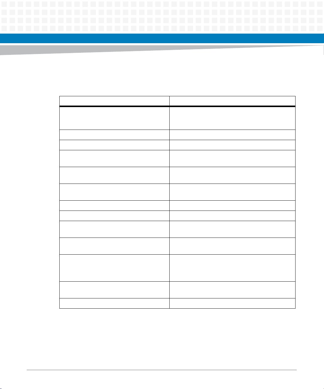
Abbreviations
This document uses the following abbreviations:
Term Definition
CPLD Complex Programmable Logic Device
DDR Double Data Rate
DDR3 Double Data Rate 3
DMI Direct Media Interface
MVME2500-ECC Installation and Use (6806800N30F)
13
About this Manual
Term Definition
DUART Dual Universal Asynchronous Receiver Transmitter
EEPROM Erasable Programmable Read-Only Memory
FCC Federal Communications Commission
Gbps Gigabits per second
IEEE Institute of Electrical and Electronics Engineers
MCP Multi-Chip Package
MRAM Magnetoresistive Random Access Memory
PCB Printed Circuit Board
PCI Peripheral Component Interconnect
PCI-E PCI Express
PCI-X Peripheral Component Interconnect eXtended
PIM PCI Mezzanine Card Input/Output Module
About this Manual
14
PLD Programmable Logic Device
PMC PCI Mezzanine Card (IEEE P1386.1)
PrPMC Processor PCI Mezzanine Card
RTC Real-Time Clock
RTM Rear Transition Module
SATA Serial Advanced Technology Attachment
UART Universal Asynchronous Receiver-Transmitter
VITA VMEbus International Trade Association
VME Versa Module Eurocard
XMC PCI eXpress Mezzanine Card
MVME2500-ECC Installation and Use (6806800N30F)
Conventions
The following table describes the conventions used throughout this manual.
Notation Description
0x00000000 Typical notation for hexadecimal numbers (digits are
0b0000 Same for binary numbers (digits are 0 and 1)
bold Used to emphasize a word
Screen Used for on-screen output and code-related
Courier + Bold Used to characterize user input and to separate it
Reference Used for references and for table and figure
About this Manual
0 through F), for example used for addresses and
offsets
elements or commands in body text
from system output
descriptions
File > Exit Notation for selecting a submenu
<text> Notation for variables and keys
[text] Notation for software buttons to click on the screen
... Repeated item for example node 1, node 2, ..., node
.
.
.
.. Ranges, for example: 0..4 means one of the integers
| Logical OR
MVME2500-ECC Installation and Use (6806800N30F)
and parameter description
12
Omission of information from example/command
that is not necessary at the time being
0,1,2,3, and 4 (used in registers)
15
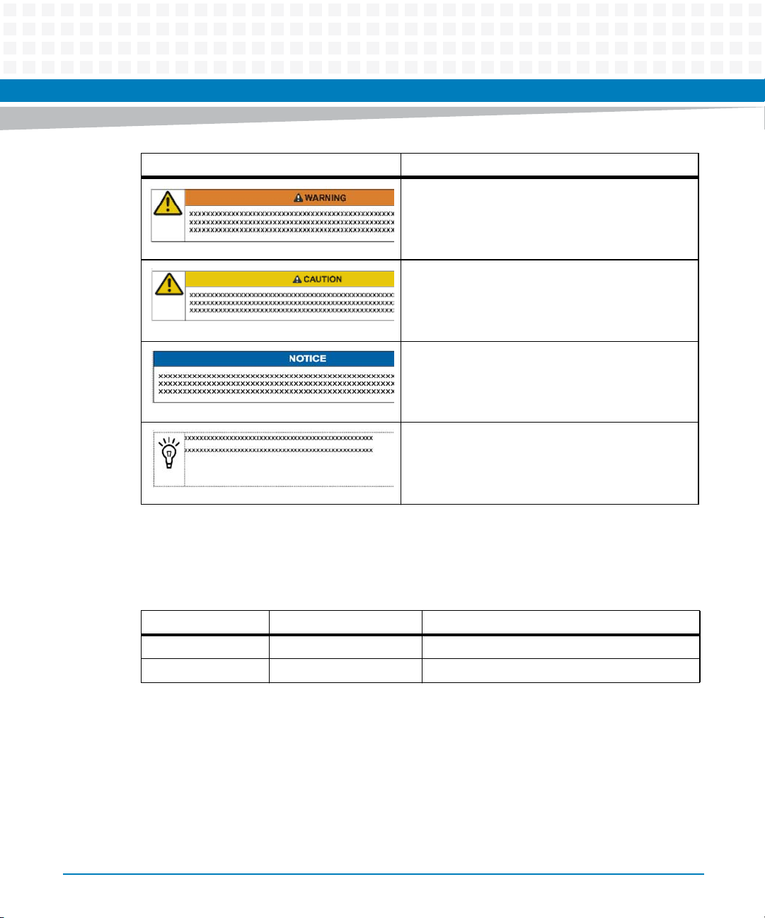
About this Manual
Notation Description
About this Manual
Indicates a hazardous situation which, if not avoided,
could result in death or serious injury
Indicates a hazardous situation which, if not avoided,
may result in minor or moderate injury
Indicates a property damage message
No danger encountered. Pay attention to important
information
Summary of Changes
This manual has been revised and replaces all prior editions.
Part Number Publication Date Description
6806800N30A November 2011 First edition
6806800N30B May 2012 ECC-related updates
16
MVME2500-ECC Installation and Use (6806800N30F)
About this Manual
Part Number Publication Date Description
6806800N30C January 2013 Updated Standard Compliances on page 22.
6806800N30D August 2013 Updated Table 1-6, Table 1-4, Table 2-1, Table
2-2, Table 3-20, Chapter 4, Functional Description,
Chapter 5, Programmable Logic Device (PLD)
Registers and Chapter 5, PLD Boot Bank Register, on
page 95.
6806800N30E December 2013 Updated Chapter 4, PMC Add-on Card, on page 78
and Chapter 5, PLD PCI/PMC/XMC Monitor Register,
on page 93.
6806800N30F August 2014 Re-branded to Artesyn template.
Added Declaration of Conformity on page24.
MVME2500-ECC Installation and Use (6806800N30F)
17

About this Manual
About this Manual
18
MVME2500-ECC Installation and Use (6806800N30F)
Introduction
1.1 Overview
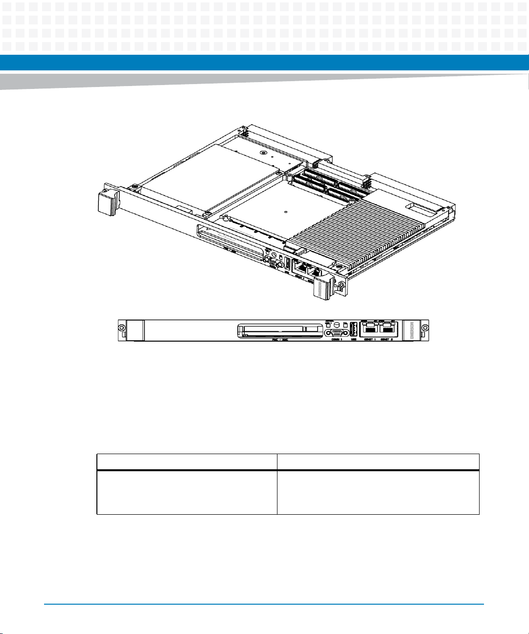
The MVME2500-ECC is a VMEbus board based on the Freescale QorlQ P2010 (single-core) or
P2020 (dual-core) processor. It has a 6U form-factor and has an expansion slot for an optional
PCI Mezzanine Card (PMC) or PCI eXpress Mezzanine Card (XMC). It comes with either 1 GB or
2 GB of DDR3 SDRAM, and is offered with either IEEE 1101.10 compliant or SCANBE ejector
handles.
The front panel I/O configuration consists of two RJ45 10/100/1000BASE-T Ethernet ports, a
USB 2.0 port, a Micro DB9 RS-232 serial console port, and a reset/abort switch. It also has an
LED to signal board failure and another LED that can be configured in the LED register.
The rear I/O includes support for VMEbus (Legacy VME, VME 64, VME64x, and 2eSST), rear
PMC/XMC I/O, RTM I/O (through VME P2), two 10/100/1000BASE-T Ethernet, four UART, and
RTM I2C/Presence/Power. See the table below for a summary of the features of the
MVME2500-ECC.
Chapter 1
Table 1-1 Key Features of the MVME2500-ECC
Function Features
Processor Freescale QorIQ P2010 (single-core) or P2020 (dual-core)
800 MHz or 1000 MHz core frequency
512 KB L2 cache
Three 10/100/1000 Mbps enhanced three-speed Ethernet
controllers (eTSECs)
Two PCI-E 1.0a x1 interface controllers
One PCI-E 1.0a x2 interface controller
USB 2.0 interface
Enhanced secure digital host controller
DDR3 memory controller at 800 MT/s
SPI interface (four chip selects, but only two are used on the
board)
Enhanced local bus controller
UART
Two I2C interfaces
Programmable interrupt controller
Memory 1 GB or 2 GB DDR3 soldered chip memory with ECC
MVME2500-ECC Installation and Use (6806800N30F)
19
Introduction
Table 1-1 Key Features of the MVME2500-ECC (continued)
Function Features
Front panel I/O Micro DB9 RS-232 serial console port
Backplane I/O VME Bus
USB 2.0
Two RJ45 10/100/1000BASE-T Ethernet
Reset/Abort switch
Fail LED and User LED
PMC/XMC front panel I/O (optional)
RTM I/O (through VME P2)
PMC/XMC I/O with P4 I/O
Two 10/100/1000BASE-T Ethernet
Four UART
RTM I2C/Presence/Power
Expansion Expansion site 1:
PMC supporting PCI-X 64/33 interface
XMC supporting PCI-E 1.0a x2 interface
Expansion site 2:
SATA drive kit
Boot Flash 16 MB SPI Flash
Persistent Data Storage 512 KB MRAM
User Flash SDHC Socket
I2C Devices Real-Time Clock
Board Temperature Sensor
8 KB VPD EEPROM
Two 64 KB User EEPROM
CPLD Watchdog, timers, and registers
Boot Firmware U-Boot-based firmware image in 16 MB SPI Flash. This flash is split
into two 8 MB chips.
20
MVME2500-ECC Installation and Use (6806800N30F)
Introduction
Table 1-1 Key Features of the MVME2500-ECC (continued)
Function Features
Operating System Based from BSP provided by Freescale which is based from
standard Linux version 2.6.32-rc3
Development tool is ltib 9.1.1 (Linux Target Image Builder)
from Freescale
VxWorks
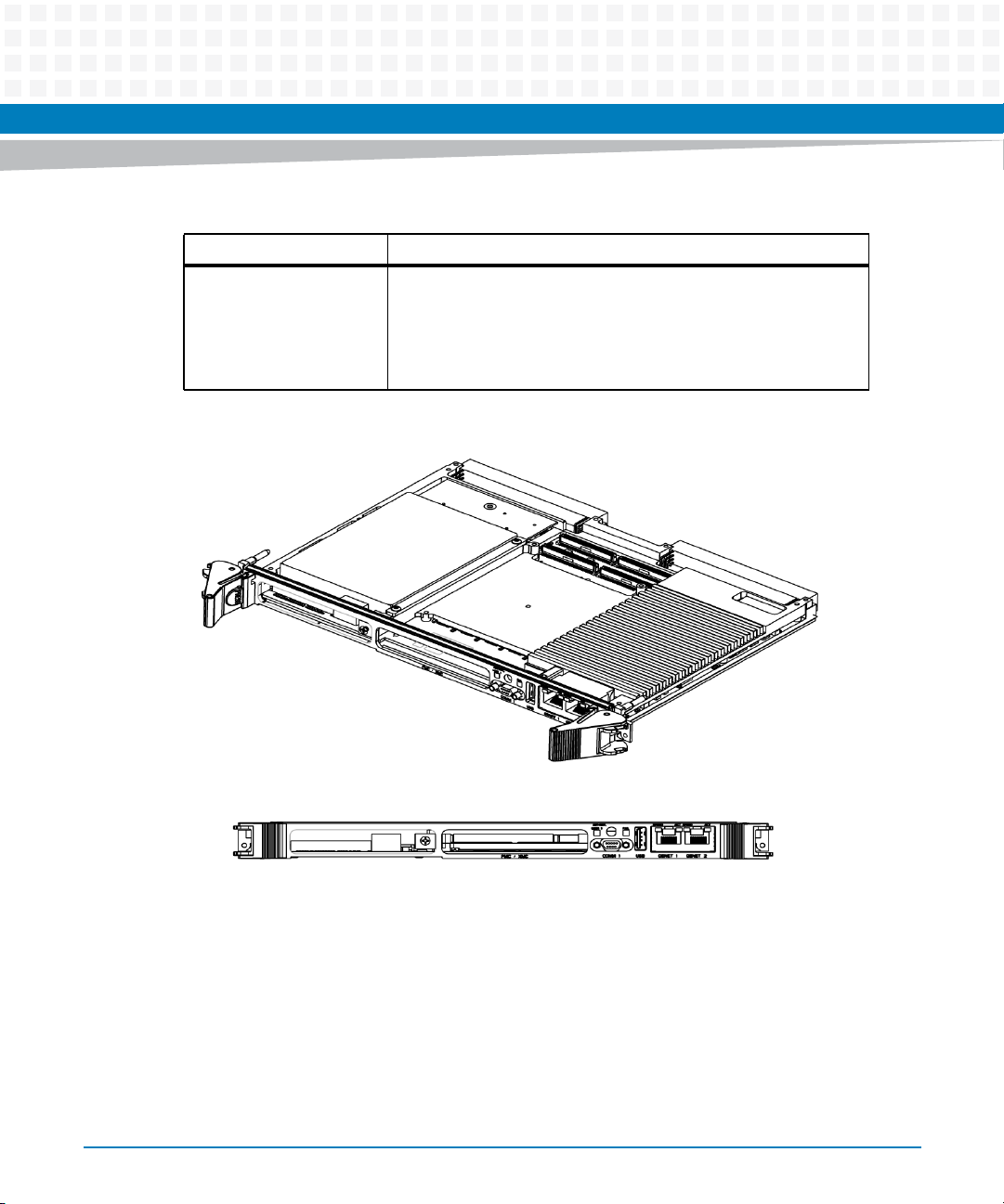
Figure 1-1 MVME2500-ECC IEEE Board
MVME2500-ECC Installation and Use (6806800N30F)
21
Introduction
Figure 1-2 MVME2500-ECC SCANBE Board
1.2 Standard Compliances
The product is designed to meet the following standards. Results are pending until testing is
finished.
Table 1-2 Board Standard Compliances
Standard Description
EN 60950-1/A11:2009
IEC 60950-1:2005 2nd Edition
CAN/CSA C22.2 No 60950-1
22
Safety Requirements (legal)
MVME2500-ECC Installation and Use (6806800N30F)
Introduction
Table 1-2 Board Standard Compliances (continued)
Standard Description
FCC Part 15, Subpart B, Class A (nonresidential)
ICES-003, Class A (non-residential)
EMC Directive 89/336/EEC
EN55022 Class B
EN55024
AS/NZS CISPR 22, Class A
EN300386
ETSI EN 300 019 series Environmental Requirements
Directive 2011/65/EU Directive on the restriction of the use of certain
EMC requirements (legal) on system level
(predefined Artesyn system)
hazardous substances in electrical and electronic
equipment (RoHS)
MVME2500-ECC Installation and Use (6806800N30F)
23

Introduction
Figure 1-3 Declaration of Conformity
E
C Declaration of Conformity
According to EN 17050-1:2004
Manufacturer’s Name:
Manufacturer’s Address:
Declares that the following product, in accordance with the requirements of 2004/108/EC, 2006/95/EC,
2011/65/EU and their amending directives,
Product:
Model Name/Number:
has been designed and manufactured to the following specifications:
EN55022:2006 Class A
EN55024: (A1: 2001 + A2: 2003): 1998
2011/65/EU RoHS Directive
As manufacturer we hereby declare that the product named above has been designed to comply with the rele-
vant sections of the above referenced specifications. This product complies with the essential health and safety
requirements of the above specified directives. We have an internal production control system that ensures
compliance between the manufactured products and the technical documentation.
Artesyn Embedded Technologies
Embedded Computing
Zhongshan General Carton Box Factory Co. Ltd. No 62, Qi
Guan Road West, Shiqi District, 528400 Zhongshan City
Guangdong, PRC
MVME2500 Series Single-Board Computers
MVME2500-01080101E, MVME2500-01080101S, MVME2500-
0161, MVME2500-0163,MVME2500-0171, MVME2500-0173,
MVME2500-02100202E, MVME2500-02100202S, MVME2500-
02120201E, MVME2500-02120201S, MVME2500-021CC,
MVME2500ET-0161, MVME2500ET-0163, MVME2500ET-0171,
MVME2500ET-0173
24
___________________________________________________ ___
03/11/2014
______
Tom Tuttle, Manager, Product Testing Services Date (MM/DD/YYYY)
MVME2500-ECC Installation and Use (6806800N30F)
1.3 Mechanical Data
The following table provides details about the dimensions and weight of the board.
Table 1-3 Mechanical Data
Feature Value
Height 233.44 mm (9.2 inches)
Depth 160.0 mm (6.3 inches)
Front Panel Height 261.8 mm (10.3 inches)
Width 19.8 mm (0.8 inches)
Max. Component Height 14.8 mm (0.58 inches)
Weight 400 grams (standard variant), 700 grams (ET variants)
Introduction
1.4 Ordering Information
Table 1-4 Available Board Variants
Marketing Number Processor Speed Memory Ejector
MVME2500-02120201E QorIQ P2020 1.2GHz 2GB IEEE
MVME2500-02120201S QorIQ P2020 1.2GHz 2GB SCANBE
MVME2500-01080101E QorIQ P2010 800 MHz 1GB IEEE
MVME2500-01080101S QorIQ P2010 800 MHz 1GB SCANBE
Table 1-5 Available Extended Temperature Variants
Marketing Number Processor Speed Memory Ejector
MVME2500ET-02100202E QorIQ P2020 1000MHZ 2GB IEEE ENP2
MVME2500ET-02100202S QorIQ P2020 1000MHZ 2GB SCANBE ENP2
MVME2500-ECC Installation and Use (6806800N30F)
25
Introduction
As of the printing date of this manual, the following board accessories are available.
Table 1-6 Available Board Accessories
Order Number Description
VME-HDMNTKIT VME HD mounting kit for standard temp variants
VME-HDMNTKIT2 VME HD MOUNTING KIT ENP2
VME-64GBSSDKIT VME 64GB SSD and mounting kit
ACC/CABLE/SER/DTE/6E SERIAL CABLE, 2m cross connected 9-pin micro-DSUB to standard 9-pin
SERIAL-MINI-D2 SERIAL CABLE - MICRO D SUB CONNECTOR TO STANDARD DB9
MVME7216E-101 VME RTM (IEEE handle)
MVME7216E-102 VME RTM (SCANBE Handle)
MVME721ET-101 VME RTM Extended Temperature (IEEE handle)
DSUB
MVME721ET-102 VME RTM Extended Temperature (SCANBE Handle)
SERIAL-MINI-D (30W2400E01A)
Female - to -male micro-mini DB-9 to DB9 adapter cable
Note: VME-HDMNTKIT can only be used with standard temp boards, MVME2500-01080101E,
MVME2500-01080101S, MVME2500-02120201E and MVME2500-02120201S.
VME-HDMNKIT2 can only be used with extended temp boards, MVME2500-02100202E and
MVME2500-02100202S.
26
MVME2500-ECC Installation and Use (6806800N30F)
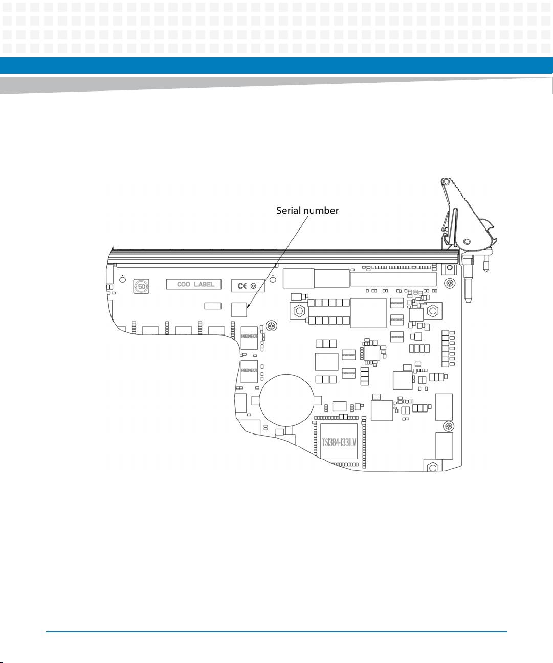
1.5 Product Identification
The following graphics shows the location of the serial number label.
Figure 1-4 Serial Number Location
Introduction
MVME2500-ECC Installation and Use (6806800N30F)
27

Introduction
28
MVME2500-ECC Installation and Use (6806800N30F)

Hardware Preparation and Installation
2.1 Overview
This chapter provides installation and safety instructions for this product. Installation
instructions for the optional PMC and transition module are also included.
A fully implemented MVME2500-ECC consists of the base board plus:
PCI Mezzanine Card (PMC) or PCI eXpress Mezzanine Card (XMC) for added versatility
Rear Transition Module (RTM)
SATA kit
The following are the things that need to be done before using the board. Be sure to read the
entire chapter, including all caution and warning notes, before you begin.
1. Unpack the hardware. Refer to Unpacking and Inspecting the Board on page 30
Chapter 2
2. Configure the hardware by setting jumpers on the board and RTM. Refer to Configuring the
Board on page 34
3. Install the transition module in the chassis. Refer to Rear Transition Module on page 35.
4. Install PMC module (if required). Refer to PMC/XMC Support on page 36.
5. Install XMC span module (if required). Refer to PMC/XMC Support on page 36.
6. Install the board in the chassis. Refer to Installing and Removing the Board on page 37.
7. Attach cables and apply power. Refer to Completing the Installation on page 39.
MVME2500-ECC Installation and Use (6806800N30F)
29
Hardware Preparation and Installation
2.2 Unpacking and Inspecting the Board
Read all notices and cautions prior to unpacking the product.
Damage of Circuits
Electrostatic discharge and incorrect installation and removal can damage circuits or
shorten its life.
Before touching the board or electronic components, make sure that you are working
in an ESD-safe environment.
Shipment Inspection
1. Verify that you have received all items of your shipment.
2. Check for damage and report any damage or differences to customer service.
3. Remove the desiccant bag shipped together with the board and dispose of it according to
your country’s legislation.
The product is thoroughly inspected before shipment. If any damage occurred during
transportation or any items are missing, contact customer service immediately.
2.3 Requirements
Make sure the board meets the requirements specified in the next sections when the board is
operated in your particular system configuration.
30
MVME2500-ECC Installation and Use (6806800N30F)
 Loading...