

Page 1

MITX-CORE-820
Installation and Use
P/N: 6806800M10H
July 2014
Page 2

©
Copyright 2014 Artesyn Embedded Technologies, Inc.
All rights reserved.
Trademarks
Artesyn Embedded Technologies, Artesyn and the Artesyn Embedded Technologies logo are trademarks and service marks of
Artesyn Embedded Technologies, Inc.© 2014 Artesyn Embedded Technologies, Inc. All other product or service names are the
property of their respective owners.
Intel® is a trademark or registered trademark of Intel Corporation or its subsidiaries in the United States and other countries.
Java™ and all other Java-based marks are trademarks or registered trademarks of Oracle America, Inc. in the U.S. and other countries.
Microsoft®, Windows® and Windows Me® are registered trademarks of Microsoft Corporation; and Windows XP™ is a trademark of
Microsoft Corporation.
PICMG®, CompactPCI®, AdvancedTCA™ and the PICMG, CompactPCI and AdvancedTCA logos are registered trademarks of the PCI
Industrial Computer Manufacturers Group.
UNIX® is a registered trademark of The Open Group in the United States and other countries.
Notice
While reasonable efforts have been made to assure the accuracy of this document, Artesyn assumes no liability resulting from any
omissions in this document, or from the use of the information obtained therein. Artesyn reserves the right to revise this document
and to make changes from time to time in the content hereof without obligation of Artesyn to notify any person of such revision or
changes.
Electronic versions of this material may be read online, downloaded for personal use, or referenced in another document as a URL to
an Artesyn website. The text itself may not be published commercially in print or electronic form, edited, translated, or otherwise
altered without the permission of Artesyn.
It is possible that this publication may contain reference to or information about Artesyn products (machines and programs),
programming, or services that are not available in your country. Such references or information must not be construed to mean that
Artesyn intends to announce such Artesyn products, programming, or services in your country.
Limited and Restricted Rights Legend
If the documentation contained herein is supplied, directly or indirectly, to the U.S. Government, the following notice shall apply
unless otherwise agreed to in writing by Artesyn.
Use, duplication, or disclosure by the Government is subject to restrictions as set forth in subparagraph (b)(3) of the Rights in
Technical Data clause at DFARS 252.227-7013 (Nov. 1995) and of the Rights in Noncommercial Computer Software and
Documentation clause at DFARS 252.227-7014 (Jun. 1995).
Contact Address
Artesyn Embedded Technologies Artesyn Embedded Technologies
Marketing Communications
2900 S. Diablo Way, Suite 190
Tempe, Arizona 85282
Lilienthalstr. 17-19
85579 Neubiberg/Munich
Germany
Page 3

Contents
Contents
About this Manual . . . . . . . . . . . . . . . . . . . . . . . . . . . . . . . . . . . . . . . . . . . . . . . . . . . . . . . . . . . . . . . . . . . . . . . 15
Safety Notes . . . . . . . . . . . . . . . . . . . . . . . . . . . . . . . . . . . . . . . . . . . . . . . . . . . . . . . . . . . . . . . . . . . . . . . . . . . . . 23
Sicherheitshinweise . . . . . . . . . . . . . . . . . . . . . . . . . . . . . . . . . . . . . . . . . . . . . . . . . . . . . . . . . . . . . . . . . . . . . . 27
1 Introduction . . . . . . . . . . . . . . . . . . . . . . . . . . . . . . . . . . . . . . . . . . . . . . . . . . . . . . . . . . . . . . . . . . . . . . . . . 31
1.1 Overview . . . . . . . . . . . . . . . . . . . . . . . . . . . . . . . . . . . . . . . . . . . . . . . . . . . . . . . . . . . . . . . . . . . . . . . . . . 31
1.2 Features . . . . . . . . . . . . . . . . . . . . . . . . . . . . . . . . . . . . . . . . . . . . . . . . . . . . . . . . . . . . . . . . . . . . . . . . . . . 31
1.3 Standard Compliances . . . . . . . . . . . . . . . . . . . . . . . . . . . . . . . . . . . . . . . . . . . . . . . . . . . . . . . . . . . . . . 33
1.4 Mechanical Specifications . . . . . . . . . . . . . . . . . . . . . . . . . . . . . . . . . . . . . . . . . . . . . . . . . . . . . . . . . . . 36
1.5 Board Identification . . . . . . . . . . . . . . . . . . . . . . . . . . . . . . . . . . . . . . . . . . . . . . . . . . . . . . . . . . . . . . . . . 37
1.6 Ordering Information . . . . . . . . . . . . . . . . . . . . . . . . . . . . . . . . . . . . . . . . . . . . . . . . . . . . . . . . . . . . . . . 38
2 Hardware Preparation and Installation . . . . . . . . . . . . . . . . . . . . . . . . . . . . . . . . . . . . . . . . . . . . . . . . . 39
2.1 Environmental and Power Requirements . . . . . . . . . . . . . . . . . . . . . . . . . . . . . . . . . . . . . . . . . . . . . . 39
2.1.1 Environmental Requirements. . . . . . . . . . . . . . . . . . . . . . . . . . . . . . . . . . . . . . . . . . . . . . . . . . 39
2.1.2 Power Requirements . . . . . . . . . . . . . . . . . . . . . . . . . . . . . . . . . . . . . . . . . . . . . . . . . . . . . . . . . 40
2.1.3 Power Dissipation . . . . . . . . . . . . . . . . . . . . . . . . . . . . . . . . . . . . . . . . . . . . . . . . . . . . . . . . . . . . 40
2.2 Unpacking and Inspecting the Board . . . . . . . . . . . . . . . . . . . . . . . . . . . . . . . . . . . . . . . . . . . . . . . . . . 41
2.3 Preparing the Installation Environment . . . . . . . . . . . . . . . . . . . . . . . . . . . . . . . . . . . . . . . . . . . . . . . . 42
2.4 Memory Module Installation . . . . . . . . . . . . . . . . . . . . . . . . . . . . . . . . . . . . . . . . . . . . . . . . . . . . . . . . . 44
2.5 Processor Cooler Installation . . . . . . . . . . . . . . . . . . . . . . . . . . . . . . . . . . . . . . . . . . . . . . . . . . . . . . . . 45
3 Controls, LEDs and Connectors. . . . . . . . . . . . . . . . . . . . . . . . . . . . . . . . . . . . . . . . . . . . . . . . . . . . . . . . . 47
3.1 Board Layout . . . . . . . . . . . . . . . . . . . . . . . . . . . . . . . . . . . . . . . . . . . . . . . . . . . . . . . . . . . . . . . . . . . . . . . 47
3.2 Connector Definitions . . . . . . . . . . . . . . . . . . . . . . . . . . . . . . . . . . . . . . . . . . . . . . . . . . . . . . . . . . . . . . . 49
3.3 LED Controls . . . . . . . . . . . . . . . . . . . . . . . . . . . . . . . . . . . . . . . . . . . . . . . . . . . . . . . . . . . . . . . . . . . . . . . 50
3.4 Rear I/O Connectors . . . . . . . . . . . . . . . . . . . . . . . . . . . . . . . . . . . . . . . . . . . . . . . . . . . . . . . . . . . . . . . . 51
4 Functional Description . . . . . . . . . . . . . . . . . . . . . . . . . . . . . . . . . . . . . . . . . . . . . . . . . . . . . . . . . . . . . . . . 53
4.1 Block Diagram . . . . . . . . . . . . . . . . . . . . . . . . . . . . . . . . . . . . . . . . . . . . . . . . . . . . . . . . . . . . . . . . . . . . . 53
MITX-CORE-820 Installation and Use (6806800M10H)
3
Page 4

Contents
Contents
Contents
4.2 Processor . . . . . . . . . . . . . . . . . . . . . . . . . . . . . . . . . . . . . . . . . . . . . . . . . . . . . . . . . . . . . . . . . . . . . . . . . . 54
4.3 Motherboard Clock Diagram . . . . . . . . . . . . . . . . . . . . . . . . . . . . . . . . . . . . . . . . . . . . . . . . . . . . . . . . . 54
4.4 Chipset . . . . . . . . . . . . . . . . . . . . . . . . . . . . . . . . . . . . . . . . . . . . . . . . . . . . . . . . . . . . . . . . . . . . . . . . . . . . 55
4.5 System Memory . . . . . . . . . . . . . . . . . . . . . . . . . . . . . . . . . . . . . . . . . . . . . . . . . . . . . . . . . . . . . . . . . . . . 55
4.6 Video . . . . . . . . . . . . . . . . . . . . . . . . . . . . . . . . . . . . . . . . . . . . . . . . . . . . . . . . . . . . . . . . . . . . . . . . . . . . . 56
4.6.1 LVDS . . . . . . . . . . . . . . . . . . . . . . . . . . . . . . . . . . . . . . . . . . . . . . . . . . . . . . . . . . . . . . . . . . . . . . . 56
4.6.2 VGA . . . . . . . . . . . . . . . . . . . . . . . . . . . . . . . . . . . . . . . . . . . . . . . . . . . . . . . . . . . . . . . . . . . . . . . . 57
4.6.3 Display Port . . . . . . . . . . . . . . . . . . . . . . . . . . . . . . . . . . . . . . . . . . . . . . . . . . . . . . . . . . . . . . . . . 58
4.6.4 Embedded Display Port (eDP) . . . . . . . . . . . . . . . . . . . . . . . . . . . . . . . . . . . . . . . . . . . . . . . . . 58
4.7 PCI Express . . . . . . . . . . . . . . . . . . . . . . . . . . . . . . . . . . . . . . . . . . . . . . . . . . . . . . . . . . . . . . . . . . . . . . . . 59
4.8 LAN on Motherboard . . . . . . . . . . . . . . . . . . . . . . . . . . . . . . . . . . . . . . . . . . . . . . . . . . . . . . . . . . . . . . . . 59
4.9 WiFi/WiMax . . . . . . . . . . . . . . . . . . . . . . . . . . . . . . . . . . . . . . . . . . . . . . . . . . . . . . . . . . . . . . . . . . . . . . . . 61
4.10 Storage . . . . . . . . . . . . . . . . . . . . . . . . . . . . . . . . . . . . . . . . . . . . . . . . . . . . . . . . . . . . . . . . . . . . . . . . . . . 61
4.11 USB 2.0 . . . . . . . . . . . . . . . . . . . . . . . . . . . . . . . . . . . . . . . . . . . . . . . . . . . . . . . . . . . . . . . . . . . . . . . . . . . 62
4.12 Power Supplies . . . . . . . . . . . . . . . . . . . . . . . . . . . . . . . . . . . . . . . . . . . . . . . . . . . . . . . . . . . . . . . . . . . . . 63
4.12.1 Power Consumption. . . . . . . . . . . . . . . . . . . . . . . . . . . . . . . . . . . . . . . . . . . . . . . . . . . . . . . . . . 64
4.12.2 Power Sequencing Requirements . . . . . . . . . . . . . . . . . . . . . . . . . . . . . . . . . . . . . . . . . . . . . . 64
4.12.3 Power Management . . . . . . . . . . . . . . . . . . . . . . . . . . . . . . . . . . . . . . . . . . . . . . . . . . . . . . . . . . 64
4.12.4 Power Measurement . . . . . . . . . . . . . . . . . . . . . . . . . . . . . . . . . . . . . . . . . . . . . . . . . . . . . . . . . 65
4.13 Embedded Controller . . . . . . . . . . . . . . . . . . . . . . . . . . . . . . . . . . . . . . . . . . . . . . . . . . . . . . . . . . . . . . . 65
4.13.1 Voltage Monitor . . . . . . . . . . . . . . . . . . . . . . . . . . . . . . . . . . . . . . . . . . . . . . . . . . . . . . . . . . . . . 65
4.13.2 Serial Port . . . . . . . . . . . . . . . . . . . . . . . . . . . . . . . . . . . . . . . . . . . . . . . . . . . . . . . . . . . . . . . . . . . 65
4.13.3 Fan Header . . . . . . . . . . . . . . . . . . . . . . . . . . . . . . . . . . . . . . . . . . . . . . . . . . . . . . . . . . . . . . . . . . 66
4.13.4 PS/2 . . . . . . . . . . . . . . . . . . . . . . . . . . . . . . . . . . . . . . . . . . . . . . . . . . . . . . . . . . . . . . . . . . . . . . . . 66
4.13.5 Debug Header . . . . . . . . . . . . . . . . . . . . . . . . . . . . . . . . . . . . . . . . . . . . . . . . . . . . . . . . . . . . . . . 67
4.13.6 Charge Board Interface . . . . . . . . . . . . . . . . . . . . . . . . . . . . . . . . . . . . . . . . . . . . . . . . . . . . . . . 67
4.14 SMBUS Architecture . . . . . . . . . . . . . . . . . . . . . . . . . . . . . . . . . . . . . . . . . . . . . . . . . . . . . . . . . . . . . . . . 68
4.15 Audio . . . . . . . . . . . . . . . . . . . . . . . . . . . . . . . . . . . . . . . . . . . . . . . . . . . . . . . . . . . . . . . . . . . . . . . . . . . . . 69
4.16 Watchdog Timer . . . . . . . . . . . . . . . . . . . . . . . . . . . . . . . . . . . . . . . . . . . . . . . . . . . . . . . . . . . . . . . . . . . 71
4.17 RTC Circuit . . . . . . . . . . . . . . . . . . . . . . . . . . . . . . . . . . . . . . . . . . . . . . . . . . . . . . . . . . . . . . . . . . . . . . . . 71
4.17.1 Boot Block . . . . . . . . . . . . . . . . . . . . . . . . . . . . . . . . . . . . . . . . . . . . . . . . . . . . . . . . . . . . . . . . . . 71
4.18 SPI Flash . . . . . . . . . . . . . . . . . . . . . . . . . . . . . . . . . . . . . . . . . . . . . . . . . . . . . . . . . . . . . . . . . . . . . . . . . . . 72
4.19 Front Panel Header . . . . . . . . . . . . . . . . . . . . . . . . . . . . . . . . . . . . . . . . . . . . . . . . . . . . . . . . . . . . . . . . . 72
4.20 TPM/Port 80 Interface . . . . . . . . . . . . . . . . . . . . . . . . . . . . . . . . . . . . . . . . . . . . . . . . . . . . . . . . . . . . . . . 73
4.21 On Board LED Interface . . . . . . . . . . . . . . . . . . . . . . . . . . . . . . . . . . . . . . . . . . . . . . . . . . . . . . . . . . . . . . 74
4.22 Case Open Header . . . . . . . . . . . . . . . . . . . . . . . . . . . . . . . . . . . . . . . . . . . . . . . . . . . . . . . . . . . . . . . . . . 74
4
MITX-CORE-820 Installation and Use (6806800M10H)
Page 5

Contents
4.23 Internal Graphics Disable . . . . . . . . . . . . . . . . . . . . . . . . . . . . . . . . . . . . . . . . . . . . . . . . . . . . . . . . . . . . 75
4.24 User GPIO Header . . . . . . . . . . . . . . . . . . . . . . . . . . . . . . . . . . . . . . . . . . . . . . . . . . . . . . . . . . . . . . . . . . 75
4.25 Debug Support . . . . . . . . . . . . . . . . . . . . . . . . . . . . . . . . . . . . . . . . . . . . . . . . . . . . . . . . . . . . . . . . . . . . . 75
4.26 Wake Events . . . . . . . . . . . . . . . . . . . . . . . . . . . . . . . . . . . . . . . . . . . . . . . . . . . . . . . . . . . . . . . . . . . . . . . 76
4.27 Manageability . . . . . . . . . . . . . . . . . . . . . . . . . . . . . . . . . . . . . . . . . . . . . . . . . . . . . . . . . . . . . . . . . . . . . . 76
5 BIOS . . . . . . . . . . . . . . . . . . . . . . . . . . . . . . . . . . . . . . . . . . . . . . . . . . . . . . . . . . . . . . . . . . . . . . . . . . . . . . . . 77
5.1 Power Up Self Test (POST) . . . . . . . . . . . . . . . . . . . . . . . . . . . . . . . . . . . . . . . . . . . . . . . . . . . . . . . . . . . 77
5.2 Boot Process . . . . . . . . . . . . . . . . . . . . . . . . . . . . . . . . . . . . . . . . . . . . . . . . . . . . . . . . . . . . . . . . . . . . . . . 77
5.3 Initiating Setup . . . . . . . . . . . . . . . . . . . . . . . . . . . . . . . . . . . . . . . . . . . . . . . . . . . . . . . . . . . . . . . . . . . . . 77
5.4 Setup Utility . . . . . . . . . . . . . . . . . . . . . . . . . . . . . . . . . . . . . . . . . . . . . . . . . . . . . . . . . . . . . . . . . . . . . . . 78
5.4.1 Main Menu . . . . . . . . . . . . . . . . . . . . . . . . . . . . . . . . . . . . . . . . . . . . . . . . . . . . . . . . . . . . . . . . . . 80
5.4.1.1 System Information . . . . . . . . . . . . . . . . . . . . . . . . . . . . . . . . . . . . . . . . . . . . . . . . . 81
5.4.1.2 Boot Features . . . . . . . . . . . . . . . . . . . . . . . . . . . . . . . . . . . . . . . . . . . . . . . . . . . . . . 81
5.4.2 Advanced Menu . . . . . . . . . . . . . . . . . . . . . . . . . . . . . . . . . . . . . . . . . . . . . . . . . . . . . . . . . . . . . 82
5.4.2.1 Boot Configuration . . . . . . . . . . . . . . . . . . . . . . . . . . . . . . . . . . . . . . . . . . . . . . . . . . 83
5.4.2.2 Processor Configuration . . . . . . . . . . . . . . . . . . . . . . . . . . . . . . . . . . . . . . . . . . . . . 84
5.4.2.3 Processor Power Management . . . . . . . . . . . . . . . . . . . . . . . . . . . . . . . . . . . . . . . 84
5.4.2.4 Peripheral Configuration . . . . . . . . . . . . . . . . . . . . . . . . . . . . . . . . . . . . . . . . . . . . . 85
5.4.2.5 HDD Configuration . . . . . . . . . . . . . . . . . . . . . . . . . . . . . . . . . . . . . . . . . . . . . . . . . . 85
5.4.2.6 Memory Configuration . . . . . . . . . . . . . . . . . . . . . . . . . . . . . . . . . . . . . . . . . . . . . . 86
5.4.2.7 System Agent (SA) Configuration . . . . . . . . . . . . . . . . . . . . . . . . . . . . . . . . . . . . . 86
5.4.2.8 South Bridge Configuration . . . . . . . . . . . . . . . . . . . . . . . . . . . . . . . . . . . . . . . . . . 88
5.4.2.9 Network Configuration . . . . . . . . . . . . . . . . . . . . . . . . . . . . . . . . . . . . . . . . . . . . . . 90
5.4.2.10 AMT Configuration . . . . . . . . . . . . . . . . . . . . . . . . . . . . . . . . . . . . . . . . . . . . . . . . . . 90
5.4.2.11 ME Configuration . . . . . . . . . . . . . . . . . . . . . . . . . . . . . . . . . . . . . . . . . . . . . . . . . . . 91
5.4.3 Security Menu . . . . . . . . . . . . . . . . . . . . . . . . . . . . . . . . . . . . . . . . . . . . . . . . . . . . . . . . . . . . . . . 92
5.4.3.1 Trusted Platform Module (TPM) Configuration . . . . . . . . . . . . . . . . . . . . . . . . . 92
5.4.4 Boot Menu . . . . . . . . . . . . . . . . . . . . . . . . . . . . . . . . . . . . . . . . . . . . . . . . . . . . . . . . . . . . . . . . . . 93
5.4.5 Exit Menu . . . . . . . . . . . . . . . . . . . . . . . . . . . . . . . . . . . . . . . . . . . . . . . . . . . . . . . . . . . . . . . . . . . 94
5.5 Miscellaneous . . . . . . . . . . . . . . . . . . . . . . . . . . . . . . . . . . . . . . . . . . . . . . . . . . . . . . . . . . . . . . . . . . . . . . 95
5.5.1 Supported OS List . . . . . . . . . . . . . . . . . . . . . . . . . . . . . . . . . . . . . . . . . . . . . . . . . . . . . . . . . . . . 95
5.5.2 Driver Control Table . . . . . . . . . . . . . . . . . . . . . . . . . . . . . . . . . . . . . . . . . . . . . . . . . . . . . . . . . . 95
5.5.3 ACPI Wake Up Support Matrix . . . . . . . . . . . . . . . . . . . . . . . . . . . . . . . . . . . . . . . . . . . . . . . . . 96
5.5.4 Default Boot Sequence . . . . . . . . . . . . . . . . . . . . . . . . . . . . . . . . . . . . . . . . . . . . . . . . . . . . . . . 96
MITX-CORE-820 Installation and Use (6806800M10H)
5
Page 6

Contents
Contents
Contents
5.6 BIOS Status Codes . . . . . . . . . . . . . . . . . . . . . . . . . . . . . . . . . . . . . . . . . . . . . . . . . . . . . . . . . . . . . . . . . . 96
5.6.1 Status Code Ranges . . . . . . . . . . . . . . . . . . . . . . . . . . . . . . . . . . . . . . . . . . . . . . . . . . . . . . . . . . 96
5.6.2 Standard Status Codes. . . . . . . . . . . . . . . . . . . . . . . . . . . . . . . . . . . . . . . . . . . . . . . . . . . . . . . . 97
5.7 Accessing the MEBX Setup Menu . . . . . . . . . . . . . . . . . . . . . . . . . . . . . . . . . . . . . . . . . . . . . . . . . . . . . 99
5.8 BIOS Update . . . . . . . . . . . . . . . . . . . . . . . . . . . . . . . . . . . . . . . . . . . . . . . . . . . . . . . . . . . . . . . . . . . . . . . 99
6 Firmware . . . . . . . . . . . . . . . . . . . . . . . . . . . . . . . . . . . . . . . . . . . . . . . . . . . . . . . . . . . . . . . . . . . . . . . . . . .101
6.1 Embedded Controller Overview . . . . . . . . . . . . . . . . . . . . . . . . . . . . . . . . . . . . . . . . . . . . . . . . . . . . . 101
6.2 System BIOS Porting . . . . . . . . . . . . . . . . . . . . . . . . . . . . . . . . . . . . . . . . . . . . . . . . . . . . . . . . . . . . . . . 102
6.2.1 Host Configuration Address . . . . . . . . . . . . . . . . . . . . . . . . . . . . . . . . . . . . . . . . . . . . . . . . . . 102
6.2.2 Index-Data Register Pair . . . . . . . . . . . . . . . . . . . . . . . . . . . . . . . . . . . . . . . . . . . . . . . . . . . . . 102
6.2.3 Blanked Logical Device Register Structure. . . . . . . . . . . . . . . . . . . . . . . . . . . . . . . . . . . . . . 102
6.2.4 Standard Logical Device Configuration Register. . . . . . . . . . . . . . . . . . . . . . . . . . . . . . . . . 105
6.2.5 KBC Address to Host Processor . . . . . . . . . . . . . . . . . . . . . . . . . . . . . . . . . . . . . . . . . . . . . . . 106
6.2.6 EC I/O Port . . . . . . . . . . . . . . . . . . . . . . . . . . . . . . . . . . . . . . . . . . . . . . . . . . . . . . . . . . . . . . . . .106
6.2.6.1 EC Status Register . . . . . . . . . . . . . . . . . . . . . . . . . . . . . . . . . . . . . . . . . . . . . . . . . . 106
6.2.7 EC Command Register . . . . . . . . . . . . . . . . . . . . . . . . . . . . . . . . . . . . . . . . . . . . . . . . . . . . . . .107
6.2.8 EC Command Program Sequence . . . . . . . . . . . . . . . . . . . . . . . . . . . . . . . . . . . . . . . . . . . . . 108
6.2.9 EC Space Definition. . . . . . . . . . . . . . . . . . . . . . . . . . . . . . . . . . . . . . . . . . . . . . . . . . . . . . . . . . 108
6.2.10 Event List. . . . . . . . . . . . . . . . . . . . . . . . . . . . . . . . . . . . . . . . . . . . . . . . . . . . . . . . . . . . . . . . . . . 112
6.2.11 OS Driver Support . . . . . . . . . . . . . . . . . . . . . . . . . . . . . . . . . . . . . . . . . . . . . . . . . . . . . . . . . . .113
6.3 EC Firmware Porting . . . . . . . . . . . . . . . . . . . . . . . . . . . . . . . . . . . . . . . . . . . . . . . . . . . . . . . . . . . . . . . 113
6.3.1 Power Sequence Control . . . . . . . . . . . . . . . . . . . . . . . . . . . . . . . . . . . . . . . . . . . . . . . . . . . . .113
6.3.2 PECI . . . . . . . . . . . . . . . . . . . . . . . . . . . . . . . . . . . . . . . . . . . . . . . . . . . . . . . . . . . . . . . . . . . . . . . 116
6.3.3 Thermal & Fan Speed Control . . . . . . . . . . . . . . . . . . . . . . . . . . . . . . . . . . . . . . . . . . . . . . . . .118
6.3.3.1 Thermal Trip . . . . . . . . . . . . . . . . . . . . . . . . . . . . . . . . . . . . . . . . . . . . . . . . . . . . . . 118
6.3.3.2 Thermal Throttling . . . . . . . . . . . . . . . . . . . . . . . . . . . . . . . . . . . . . . . . . . . . . . . . . 118
6.3.4 Battery Information - Charging & Discharging Control . . . . . . . . . . . . . . . . . . . . . . . . . . . 118
6.3.5 Voltage Monitor . . . . . . . . . . . . . . . . . . . . . . . . . . . . . . . . . . . . . . . . . . . . . . . . . . . . . . . . . . . .119
6.3.6 Wake Up Requirement. . . . . . . . . . . . . . . . . . . . . . . . . . . . . . . . . . . . . . . . . . . . . . . . . . . . . . . 120
6.3.7 LEDs Control. . . . . . . . . . . . . . . . . . . . . . . . . . . . . . . . . . . . . . . . . . . . . . . . . . . . . . . . . . . . . . . . 120
6.3.8 PS2 Interface & Device Configuration . . . . . . . . . . . . . . . . . . . . . . . . . . . . . . . . . . . . . . . . . .121
6.3.9 Input Events Detection through GPIO. . . . . . . . . . . . . . . . . . . . . . . . . . . . . . . . . . . . . . . . . . 121
6.4 EC Firmware Flash . . . . . . . . . . . . . . . . . . . . . . . . . . . . . . . . . . . . . . . . . . . . . . . . . . . . . . . . . . . . . . . . . 122
6.4.1 Flash with SF100 . . . . . . . . . . . . . . . . . . . . . . . . . . . . . . . . . . . . . . . . . . . . . . . . . . . . . . . . . . . . 122
6
MITX-CORE-820 Installation and Use (6806800M10H)
Page 7

Contents
6.4.2 Flash with ECDT. . . . . . . . . . . . . . . . . . . . . . . . . . . . . . . . . . . . . . . . . . . . . . . . . . . . . . . . . . . . . 122
6.4.3 Flash with Utility . . . . . . . . . . . . . . . . . . . . . . . . . . . . . . . . . . . . . . . . . . . . . . . . . . . . . . . . . . . .122
6.4.4 Crisis Recovery. . . . . . . . . . . . . . . . . . . . . . . . . . . . . . . . . . . . . . . . . . . . . . . . . . . . . . . . . . . . . . 122
6.5 EC Debug Interface . . . . . . . . . . . . . . . . . . . . . . . . . . . . . . . . . . . . . . . . . . . . . . . . . . . . . . . . . . . . . . . . 122
6.5.1 Serial Port . . . . . . . . . . . . . . . . . . . . . . . . . . . . . . . . . . . . . . . . . . . . . . . . . . . . . . . . . . . . . . . . . . 122
6.5.2 JTAG Interface . . . . . . . . . . . . . . . . . . . . . . . . . . . . . . . . . . . . . . . . . . . . . . . . . . . . . . . . . . . . . . 123
A Replacing the Battery . . . . . . . . . . . . . . . . . . . . . . . . . . . . . . . . . . . . . . . . . . . . . . . . . . . . . . . . . . . . . . . . 125
A.1 Overview . . . . . . . . . . . . . . . . . . . . . . . . . . . . . . . . . . . . . . . . . . . . . . . . . . . . . . . . . . . . . . . . . . . . . . . . .125
A.2 Procedure Description . . . . . . . . . . . . . . . . . . . . . . . . . . . . . . . . . . . . . . . . . . . . . . . . . . . . . . . . . . . . . 126
B Related Documentation. . . . . . . . . . . . . . . . . . . . . . . . . . . . . . . . . . . . . . . . . . . . . . . . . . . . . . . . . . . . . . 129
B.1 Artesyn Embedded Technologies - Embedded Computing Documentation . . . . . . . . . . . . . . .129
MITX-CORE-820 Installation and Use (6806800M10H)
7
Page 8

Contents
Contents
Contents
8
MITX-CORE-820 Installation and Use (6806800M10H)
Page 9

List of Tables
Table 1-1 MITX-CORE-820 Features Summary . . . . . . . . . . . . . . . . . . . . . . . . . . . . . . . . . . . . . . . . . . . . . . 31
Table 1-2 Board Standard Compliances . . . . . . . . . . . . . . . . . . . . . . . . . . . . . . . . . . . . . . . . . . . . . . . . . . . . 33
Table 1-3 Ordering Information . . . . . . . . . . . . . . . . . . . . . . . . . . . . . . . . . . . . . . . . . . . . . . . . . . . . . . . . . . . 38
Table 2-1 Environmental Requirements . . . . . . . . . . . . . . . . . . . . . . . . . . . . . . . . . . . . . . . . . . . . . . . . . . . . 39
Table 2-2 Power Dissipation of Critical Components . . . . . . . . . . . . . . . . . . . . . . . . . . . . . . . . . . . . . . . . . 40
Table 3-1 MITX-CORE-820 Connectors . . . . . . . . . . . . . . . . . . . . . . . . . . . . . . . . . . . . . . . . . . . . . . . . . . . . . 49
Table 3-2 LED Control Indicator . . . . . . . . . . . . . . . . . . . . . . . . . . . . . . . . . . . . . . . . . . . . . . . . . . . . . . . . . . . 50
Table 4-1 PCH SKUs . . . . . . . . . . . . . . . . . . . . . . . . . . . . . . . . . . . . . . . . . . . . . . . . . . . . . . . . . . . . . . . . . . . . . 55
Table 4-2 LVDS Connector (P6) . . . . . . . . . . . . . . . . . . . . . . . . . . . . . . . . . . . . . . . . . . . . . . . . . . . . . . . . . . . 56
Table 4-3 LVDS Panel VDD Selector (P29) . . . . . . . . . . . . . . . . . . . . . . . . . . . . . . . . . . . . . . . . . . . . . . . . . . 57
Table 4-4 LVDS Inverter Connector (P8) . . . . . . . . . . . . . . . . . . . . . . . . . . . . . . . . . . . . . . . . . . . . . . . . . . . . 57
Table 4-5 eDP Connector (J15) . . . . . . . . . . . . . . . . . . . . . . . . . . . . . . . . . . . . . . . . . . . . . . . . . . . . . . . . . . . 58
Table 4-6 LAN1 Connector . . . . . . . . . . . . . . . . . . . . . . . . . . . . . . . . . . . . . . . . . . . . . . . . . . . . . . . . . . . . . . . 60
Table 4-7 LAN2 Connector . . . . . . . . . . . . . . . . . . . . . . . . . . . . . . . . . . . . . . . . . . . . . . . . . . . . . . . . . . . . . . . 60
Table 4-8 SATA HDD Power Connector Pinout (P17) . . . . . . . . . . . . . . . . . . . . . . . . . . . . . . . . . . . . . . . . . 61
Table 4-9 USB Internal Header (P24, P25, P26) Pinout . . . . . . . . . . . . . . . . . . . . . . . . . . . . . . . . . . . . . . . 62
Table 4-10 DC-IN Jack Pin Definitions . . . . . . . . . . . . . . . . . . . . . . . . . . . . . . . . . . . . . . . . . . . . . . . . . . . . . . . 63
Table 4-11 ATX Power Supply Connector (J12) . . . . . . . . . . . . . . . . . . . . . . . . . . . . . . . . . . . . . . . . . . . . . . . 63
Table 4-12 Board MAX Power Consumption Estimation . . . . . . . . . . . . . . . . . . . . . . . . . . . . . . . . . . . . . . . 64
Table 4-13 Serial Port Connectors (J5) . . . . . . . . . . . . . . . . . . . . . . . . . . . . . . . . . . . . . . . . . . . . . . . . . . . . . . 65
Table 4-14 CPU and System Fan Headers (P2 and P23) Description . . . . . . . . . . . . . . . . . . . . . . . . . . . . . 66
Table 4-15 PS/2 Header (P5) Description . . . . . . . . . . . . . . . . . . . . . . . . . . . . . . . . . . . . . . . . . . . . . . . . . . . . 66
Table 4-16 EC Debug Header (P14) Description . . . . . . . . . . . . . . . . . . . . . . . . . . . . . . . . . . . . . . . . . . . . . . 67
Table 4-17 Charge Board Interface (P22) . . . . . . . . . . . . . . . . . . . . . . . . . . . . . . . . . . . . . . . . . . . . . . . . . . . . 67
Table 4-18 Audio Jack Board Side Pin Definitions (J11) . . . . . . . . . . . . . . . . . . . . . . . . . . . . . . . . . . . . . . . . 69
Table 4-19 Front Panel Audio Header (P9) Description . . . . . . . . . . . . . . . . . . . . . . . . . . . . . . . . . . . . . . . . 70
Table 4-20 S/PDIF Out Header (P30) . . . . . . . . . . . . . . . . . . . . . . . . . . . . . . . . . . . . . . . . . . . . . . . . . . . . . . . . 71
Table 4-21 Clear CMOS Header (P4) . . . . . . . . . . . . . . . . . . . . . . . . . . . . . . . . . . . . . . . . . . . . . . . . . . . . . . . . 71
Table 4-22 Front Panel Header (P1) Definition . . . . . . . . . . . . . . . . . . . . . . . . . . . . . . . . . . . . . . . . . . . . . . . 72
Table 4-23 TPM/Port80 Header (P3) Definition . . . . . . . . . . . . . . . . . . . . . . . . . . . . . . . . . . . . . . . . . . . . . . 73
Table 4-24 Charge LED 1 (P31) . . . . . . . . . . . . . . . . . . . . . . . . . . . . . . . . . . . . . . . . . . . . . . . . . . . . . . . . . . . . . 74
Table 4-25 Charge LED 2 (P34) . . . . . . . . . . . . . . . . . . . . . . . . . . . . . . . . . . . . . . . . . . . . . . . . . . . . . . . . . . . . . 74
Table 4-26 Case Open Header (P27) . . . . . . . . . . . . . . . . . . . . . . . . . . . . . . . . . . . . . . . . . . . . . . . . . . . . . . . . 74
Table 4-27 Internal Graphics Disable Header (P33) . . . . . . . . . . . . . . . . . . . . . . . . . . . . . . . . . . . . . . . . . . . 75
Table 4-28 User GPIO Header (P28) . . . . . . . . . . . . . . . . . . . . . . . . . . . . . . . . . . . . . . . . . . . . . . . . . . . . . . . . . 75
Table 4-29 Wake Up Header (P18) . . . . . . . . . . . . . . . . . . . . . . . . . . . . . . . . . . . . . . . . . . . . . . . . . . . . . . . . . . 76
MITX-CORE-820 Installation and Use (6806800M10H)
9
Page 10

List of Tables
Table 5-1 BIOS Primary Menu . . . . . . . . . . . . . . . . . . . . . . . . . . . . . . . . . . . . . . . . . . . . . . . . . . . . . . . . . . . . . 78
Table 5-2 Phoenix Navigation . . . . . . . . . . . . . . . . . . . . . . . . . . . . . . . . . . . . . . . . . . . . . . . . . . . . . . . . . . . . . 78
Table 5-3 Main Menu Field Description . . . . . . . . . . . . . . . . . . . . . . . . . . . . . . . . . . . . . . . . . . . . . . . . . . . . . 80
Table 5-4 System Information Field Description . . . . . . . . . . . . . . . . . . . . . . . . . . . . . . . . . . . . . . . . . . . . . 81
Table 5-5 Boot Features Field Description . . . . . . . . . . . . . . . . . . . . . . . . . . . . . . . . . . . . . . . . . . . . . . . . . . 81
Table 5-6 Advanced Menu Field Description . . . . . . . . . . . . . . . . . . . . . . . . . . . . . . . . . . . . . . . . . . . . . . . . 82
Table 5-7 Boot Configuration Field Description . . . . . . . . . . . . . . . . . . . . . . . . . . . . . . . . . . . . . . . . . . . . . 83
Table 5-8 Processor Configuration Field Description . . . . . . . . . . . . . . . . . . . . . . . . . . . . . . . . . . . . . . . . . 84
Table 5-9 Processor Power Management Field Description . . . . . . . . . . . . . . . . . . . . . . . . . . . . . . . . . . . 84
Table 5-10 Peripheral Configuration Field Description . . . . . . . . . . . . . . . . . . . . . . . . . . . . . . . . . . . . . . . . . 85
Table 5-11 HDD Configuration Field Description . . . . . . . . . . . . . . . . . . . . . . . . . . . . . . . . . . . . . . . . . . . . . 85
Table 5-12 Software Feature Mask Configuration Field Description . . . . . . . . . . . . . . . . . . . . . . . . . . . . . 86
Table 5-13 Memory Configuration Field Description . . . . . . . . . . . . . . . . . . . . . . . . . . . . . . . . . . . . . . . . . . 86
Table 5-14 SA Configuration Field Description . . . . . . . . . . . . . . . . . . . . . . . . . . . . . . . . . . . . . . . . . . . . . . . 86
Table 5-15 Intel(R) VT for Directed I/O (VT-d) Field Description . . . . . . . . . . . . . . . . . . . . . . . . . . . . . . . . .87
Table 5-16 Graphics Configuration . . . . . . . . . . . . . . . . . . . . . . . . . . . . . . . . . . . . . . . . . . . . . . . . . . . . . . . . . 87
Table 5-17 IGD Configuration . . . . . . . . . . . . . . . . . . . . . . . . . . . . . . . . . . . . . . . . . . . . . . . . . . . . . . . . . . . . . . 88
Table 5-18 South Bridge Configuration Field Description . . . . . . . . . . . . . . . . . . . . . . . . . . . . . . . . . . . . . . 88
Table 5-19 SB PCI Express Configuration Field Description . . . . . . . . . . . . . . . . . . . . . . . . . . . . . . . . . . . . . 89
Table 5-20 PCI Express Port 3//7/8 Configuration Field Description . . . . . . . . . . . . . . . . . . . . . . . . . . . . . 89
Table 5-21 SB USB Configuration Field Description . . . . . . . . . . . . . . . . . . . . . . . . . . . . . . . . . . . . . . . . . . . 89
Table 5-22 SB Azalia Configuration Field Description . . . . . . . . . . . . . . . . . . . . . . . . . . . . . . . . . . . . . . . . . . 90
Table 5-23 Network Configuration Field Description . . . . . . . . . . . . . . . . . . . . . . . . . . . . . . . . . . . . . . . . . .90
Table 5-24 AMT Configuration Field Description . . . . . . . . . . . . . . . . . . . . . . . . . . . . . . . . . . . . . . . . . . . . . . 90
Table 5-25 ME Configuration Field Description . . . . . . . . . . . . . . . . . . . . . . . . . . . . . . . . . . . . . . . . . . . . . . . 91
Table 5-26 TPM Configuration Field Description . . . . . . . . . . . . . . . . . . . . . . . . . . . . . . . . . . . . . . . . . . . . . . 92
Table 5-27 Exit Menu Field Description . . . . . . . . . . . . . . . . . . . . . . . . . . . . . . . . . . . . . . . . . . . . . . . . . . . . . . 94
Table 5-28 Driver Control Table . . . . . . . . . . . . . . . . . . . . . . . . . . . . . . . . . . . . . . . . . . . . . . . . . . . . . . . . . . . .95
Table 5-29 ACPI Wake Up Support Matrix . . . . . . . . . . . . . . . . . . . . . . . . . . . . . . . . . . . . . . . . . . . . . . . . . . . 96
Table 5-30 Status Code Ranges . . . . . . . . . . . . . . . . . . . . . . . . . . . . . . . . . . . . . . . . . . . . . . . . . . . . . . . . . . . . 96
Table 5-31 Component Status Codes . . . . . . . . . . . . . . . . . . . . . . . . . . . . . . . . . . . . . . . . . . . . . . . . . . . . . . . 97
Table 5-32 Progress Status Codes . . . . . . . . . . . . . . . . . . . . . . . . . . . . . . . . . . . . . . . . . . . . . . . . . . . . . . . . . .98
Table 5-33 Architectural Status Codes . . . . . . . . . . . . . . . . . . . . . . . . . . . . . . . . . . . . . . . . . . . . . . . . . . . . . . 98
Table 6-1 LDN Values . . . . . . . . . . . . . . . . . . . . . . . . . . . . . . . . . . . . . . . . . . . . . . . . . . . . . . . . . . . . . . . . . . .102
Table 6-2 Standard Configuration Register Map . . . . . . . . . . . . . . . . . . . . . . . . . . . . . . . . . . . . . . . . . . . .105
Table 6-3 Mapping of Host Interface Registers to the Host Processor . . . . . . . . . . . . . . . . . . . . . . . . .106
10
MITX-CORE-820 Installation and Use (6806800M10H)
Page 11

List of Tables
Table 6-4 EC Status I/O Port Register . . . . . . . . . . . . . . . . . . . . . . . . . . . . . . . . . . . . . . . . . . . . . . . . . . . . . 106
Table 6-5 EC Command Register . . . . . . . . . . . . . . . . . . . . . . . . . . . . . . . . . . . . . . . . . . . . . . . . . . . . . . . . . 107
Table 6-6 EC Command Program Sequence . . . . . . . . . . . . . . . . . . . . . . . . . . . . . . . . . . . . . . . . . . . . . . . 108
Table 6-7 EC Space Definition . . . . . . . . . . . . . . . . . . . . . . . . . . . . . . . . . . . . . . . . . . . . . . . . . . . . . . . . . . . 108
Table 6-8 Q Event List . . . . . . . . . . . . . . . . . . . . . . . . . . . . . . . . . . . . . . . . . . . . . . . . . . . . . . . . . . . . . . . . . . 112
Table 6-9 Thermal Trip Levels . . . . . . . . . . . . . . . . . . . . . . . . . . . . . . . . . . . . . . . . . . . . . . . . . . . . . . . . . . . . 118
Table 6-10 LED Control Status . . . . . . . . . . . . . . . . . . . . . . . . . . . . . . . . . . . . . . . . . . . . . . . . . . . . . . . . . . . . 120
Table B-1 Artesyn Embedded Technologies - Embedded Computing Publications . . . . . . . . . . . . . . 129
MITX-CORE-820 Installation and Use (6806800M10H)
11
Page 12

List of Tables
12
MITX-CORE-820 Installation and Use (6806800M10H)
Page 13

List of Figures
Figure 1-1 Declaration of Conformity . . . . . . . . . . . . . . . . . . . . . . . . . . . . . . . . . . . . . . . . . . . . . . . . 35
Figure 1-2 MITX-CORE-820 Mechanical Data (Top View) . . . . . . . . . . . . . . . . . . . . . . . . . . . . . . . 36
Figure 1-3 MITX-CORE-820 Mechanical Data (Side View) . . . . . . . . . . . . . . . . . . . . . . . . . . . . . . . 37
Figure 1-4 MITX-CORE-820 Serial Number Location . . . . . . . . . . . . . . . . . . . . . . . . . . . . . . . . . . . 37
Figure 3-1 MITX-CORE-820 Module Components . . . . . . . . . . . . . . . . . . . . . . . . . . . . . . . . . . . . . 47
Figure 3-2 MITX-CORE-820 Module Components - Continued . . . . . . . . . . . . . . . . . . . . . . . . . . 48
Figure 3-3 Rear I/O Connectors . . . . . . . . . . . . . . . . . . . . . . . . . . . . . . . . . . . . . . . . . . . . . . . . . . . . . 51
Figure 4-1 Block Diagram . . . . . . . . . . . . . . . . . . . . . . . . . . . . . . . . . . . . . . . . . . . . . . . . . . . . . . . . . . 53
Figure 4-2 Platform Clocks Distribution . . . . . . . . . . . . . . . . . . . . . . . . . . . . . . . . . . . . . . . . . . . . . . 54
Figure 4-3 LVDS Inverter Connector (P8) . . . . . . . . . . . . . . . . . . . . . . . . . . . . . . . . . . . . . . . . . . . . . 57
Figure 4-4 SATA HDD Power Connector (P17) . . . . . . . . . . . . . . . . . . . . . . . . . . . . . . . . . . . . . . . . 61
Figure 4-5 USB Internal Header (P24, P25, P26) . . . . . . . . . . . . . . . . . . . . . . . . . . . . . . . . . . . . . . . 62
Figure 4-6 DC-IN Jack Front View . . . . . . . . . . . . . . . . . . . . . . . . . . . . . . . . . . . . . . . . . . . . . . . . . . . . 63
Figure 4-7 ATX Power Supply Connector Top View . . . . . . . . . . . . . . . . . . . . . . . . . . . . . . . . . . . . 64
Figure 4-8 CPU and System Fan Headers (P2 and P23) . . . . . . . . . . . . . . . . . . . . . . . . . . . . . . . . . 66
Figure 4-9 PS/2 Header (P5) . . . . . . . . . . . . . . . . . . . . . . . . . . . . . . . . . . . . . . . . . . . . . . . . . . . . . . . . 67
Figure 4-10 SMBUS Architecture . . . . . . . . . . . . . . . . . . . . . . . . . . . . . . . . . . . . . . . . . . . . . . . . . . . . . 68
Figure 4-11 Rear Panel Audio Jack . . . . . . . . . . . . . . . . . . . . . . . . . . . . . . . . . . . . . . . . . . . . . . . . . . . . 70
Figure 4-12 Front Panel Audio Header (P9) . . . . . . . . . . . . . . . . . . . . . . . . . . . . . . . . . . . . . . . . . . . . 70
Figure 4-13 Front Panel Header (P1) . . . . . . . . . . . . . . . . . . . . . . . . . . . . . . . . . . . . . . . . . . . . . . . . . . 72
Figure 4-14 TPM/Port80 Header (P3) . . . . . . . . . . . . . . . . . . . . . . . . . . . . . . . . . . . . . . . . . . . . . . . . . 73
Figure 5-1 Main Menu . . . . . . . . . . . . . . . . . . . . . . . . . . . . . . . . . . . . . . . . . . . . . . . . . . . . . . . . . . . . . 80
Figure 5-2 Advanced Menu . . . . . . . . . . . . . . . . . . . . . . . . . . . . . . . . . . . . . . . . . . . . . . . . . . . . . . . . . 82
Figure 5-3 Security Menu . . . . . . . . . . . . . . . . . . . . . . . . . . . . . . . . . . . . . . . . . . . . . . . . . . . . . . . . . . 92
Figure 5-4 Boot Menu . . . . . . . . . . . . . . . . . . . . . . . . . . . . . . . . . . . . . . . . . . . . . . . . . . . . . . . . . . . . . 93
Figure 5-5 Exit Menu . . . . . . . . . . . . . . . . . . . . . . . . . . . . . . . . . . . . . . . . . . . . . . . . . . . . . . . . . . . . . . 94
Figure 6-1 NPCE791x System Block Diagram . . . . . . . . . . . . . . . . . . . . . . . . . . . . . . . . . . . . . . . . 101
Figure 6-2 Structure of Standard Configuration Register . . . . . . . . . . . . . . . . . . . . . . . . . . . . . . 104
Figure A-1 Battery Location . . . . . . . . . . . . . . . . . . . . . . . . . . . . . . . . . . . . . . . . . . . . . . . . . . . . . . . 125
MITX-CORE-820 Installation and Use (6806800M10H)
13
Page 14

List of Figures
14
MITX-CORE-820 Installation and Use (6806800M10H)
Page 15
About this Manual
Overview of Contents
This manual is divided into the following chapters and appendices.
Introduction describes the features of the MITX-CORE-820 processors, standard
compliances, mechanical data and ordering information.
Hardware Preparation and Installation describes the environmental and power
requirements, installation prerequisites, processor cooler and memory module
installation and removal procedures.
Controls, LEDs and Connectors describes the LEDs and connectors used on the
motherboard.
Functional Description describes the functionalities provided on the motherboard.
Firmware describes the motherboard’s firmware.
BIOS describes the motherboard’s firmware
Replacing the Battery contains the procedures for replacing the battery.
Related Documentation provides a listing of related product documentation,
manufacturer’s documents, and industry standard specifications.
Abbreviations
This document uses the following abbreviations:
Abbreviation Definition
AAmps
A/D Analog/Digital
AMT Active Management Technology
ANSI American National Standard Institute
BGA Ball Grid Array
COM Communications
CPU Central Processing Unit
CRC Cyclic Redundancy Check
DDR Double Data Rate
MITX-CORE-820 Installation and Use (6806800M10H)
15
Page 16
About this Manual
Abbreviation Definition
oC Degrees Celsius
DMA Direct Memory Access
DMC Display Mini Card
DRAM Dynamic Random Access Memory
ECC Error Correction Code
eDP Embedded Display Port
EEPROM Electrically Erasable Programmable Read-Only Memory
EPROM Erasable Programmable Read-Only Memory
FCC Federal Communications Commission
F/W Firmware
FPBGA Flip Chip Plastic Ball Grid Array
GB GigaBytes
About this Manual
16
GbE Gigabit Ethernet
Gbit Gigabit
Gbps Gigabits Per Second
GLCI Gigabit LAN Connect Interface
H/W Hardware
I/O Input/Output
IEEE Institute of Electrical and Electronics Engineers
I2C Inter IC
JTAG Joint Test Access Group
KB Kilo Bytes
KBAUD Kilo Baud
LCD Liquid Crystal Display
LED Light Emitting Diode
LVDS Low Voltage Differential Signaling
MB MegaBytes
Mbit Megabit
MITX-CORE-820 Installation and Use (6806800M10H)
Page 17
Abbreviation Definition
Mbps Megabits Per Second
MHz Megahertz
MTBF Mean Time Between Failure
OS Operating System
PBGA Plastic Ball Grid Array
PCI Peripheral Component Interconnect
PLL Phase-Locked Loop
POR Power-On Reset
PRD Product Requirements Document
RAM Random Access Memory
Rcv Receive
About this Manual
ROM Read-Only Memory
RTC Real-Time Clock
SATA Serial AT Attachment
SDRAM Synchronous Dynamic Random Access Memory
SMT Surface Mount Technology
SODIMM Small-Outline Dual In-line Memory Module
SPD Serial Presence Detect
SRAM Static Random Access Memory
S/W Software
USB Universal Serial Bus
V Volts
VIO Input/Output Voltage
W Watts
XDP Extended Debug Port
MITX-CORE-820 Installation and Use (6806800M10H)
17
Page 18
About this Manual
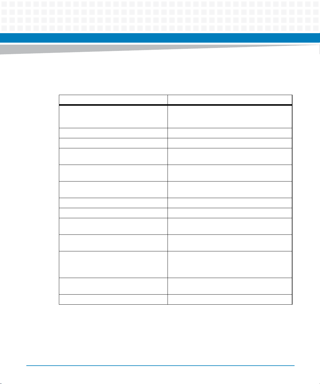
Conventions
The following table describes the conventions used throughout this manual.
Notation Description
0x00000000 Typical notation for hexadecimal numbers (digits are
0b0000 Same for binary numbers (digits are 0 and 1)
bold Used to emphasize a word
Screen Used for on-screen output and code related elements
Courier + Bold Used to characterize user input and to separate it
Reference Used for references and for table and figure
About this Manual
0 through F), for example used for addresses and
offsets
or commands in body text
from system output
descriptions
18
File > Exit Notation for selecting a submenu
<text> Notation for variables and keys
[text] Notation for software buttons to click on the screen
and parameter description
... Repeated item for example node 1, node 2, ..., node
12
.
.
.
.. Ranges, for example: 0..4 means one of the integers
| Logical OR
Omission of information from example/command
that is not necessary at the time being
0,1,2,3, and 4 (used in registers)
MITX-CORE-820 Installation and Use (6806800M10H)
Page 19
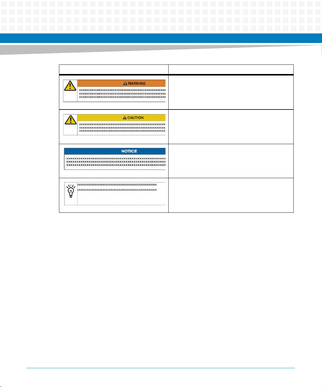
Notation Description
Indicates a hazardous situation which, if not avoided,
could result in death or serious injury
Indicates a hazardous situation which, if not avoided,
may result in minor or moderate injury
Indicates a property damage message
No danger encountered. Pay attention to important
information
About this Manual
MITX-CORE-820 Installation and Use (6806800M10H)
19
Page 20
About this Manual
Summary of Changes
This manual has been revised and replaces all prior editions.
Part Number Publication Date Description
6806800M10H July 2014 Re-branded to Artesyn template.
6806800M10G February 2012 Updated Supported OS List on page 95
6806800M10F November 2011 Added BIOS
About this Manual
Added Accessing the MEBX Setup Menu on
page 99 and BIOS Update on page 99
Updated Figure "MITX-CORE-820 Module
Components" on page 47 and Figure "MITXCORE-820 Module Components Continued" on page 48
Editorial edits, changes in information,
updates.
6806800M10E September 2011 Updated Figure "MITX-CORE-820 Module
Components" on page 47
Updated Ordering Information
20
MITX-CORE-820 Installation and Use (6806800M10H)
Page 21
About this Manual
Part Number Publication Date Description
6806800M10D August 2011 Updated marketing name to MITX-CORE-
820
Updated Table "MITX-CORE-820 Features
Summary" on page 31
Updated Table "Environmental
Requirements" on page 39
Updated Table "Power Dissipation of Critical
Components" on page 40
Updated
Figure "MITX-CORE-820 Module
Components" on page 47
Updated Table "DC-IN Jack Pin Definitions" on
page 63
Updated Table "ATX Power Supply
Connector (J12)" on page 63
Updated Table "Board MAX Power
Consumption Estimation" on page 64
6806800M10C July 2011 Updated Figure "MITX-CORE-820 Module
6806800M10B May 2011 Changed marketing name to MITX-CORE-
6806800M10A May 2011 First edition
MITX-CORE-820 Installation and Use (6806800M10H)
Components" on page 47.
Added information on the board CPU specs.
810/820.
Implemented editorial changes.
21
Page 22

About this Manual
About this Manual
22
MITX-CORE-820 Installation and Use (6806800M10H)
Page 23

Safety Notes
This section provides warnings that precede potentially dangerous procedures throughout
this manual. Instructions contained in the warnings must be followed during all phases of
operation, service, and repair of this equipment. You should also employ all other safety
precautions necessary for the operation of the equipment in your operating environment.
Failure to comply with these precautions or with specific warnings elsewhere in this manual
could result in personal injury or damage to the equipment.
Artesyn intends to provide all necessary information to install and handle the product in this
manual. Because of the complexity of this product and its various uses, we do not guarantee
that the given information is complete. If you need additional information, ask your Artesyn
representative.
The product has been designed to meet the standard industrial safety requirements. It must
only be used in its specific area of office telecommunication industry, industrial control, and
development. It must not be used in safety critical components, life supporting devices or on
aircraft.
Only personnel trained by Artesyn or persons qualified in electronics or electrical engineering
are authorized to install, remove or maintain the product. The information given in this manual
is meant to complete the knowledge of a specialist and must not be used as replacement for
qualified personnel.
Keep away from live circuits inside the equipment. Operating personnel must not remove
equipment covers. Only factory authorized service personnel or other qualified service
personnel is allowed to remove equipment covers for internal subassembly or component
replacement or any internal adjustment.
Do not install substitute parts or perform any unauthorized modification of the equipment or
the warranty may be voided. Contact your local Artesyn representative for service and repair
to make sure that all safety features are maintained.
Artesyn and our suppliers take significant steps to make sure that there are no bent pins on the
backplane or connector damage to the boards prior to leaving the factory. Bent pins caused by
improper installation or by inserting boards with damaged connectors could void the Artesyn
warranty for the backplane or boards.
This product operates with dangerous voltages that can cause injury or death. Use extreme
caution when handling, testing, and adjusting this equipment and its components.
MITX-CORE-820 Installation and Use (6806800M10H)
23
Page 24

Safety Notes
System Installation
Damage of Circuits
Electrostatic discharge and incorrect installation and removal of the product can damage
circuits or shorten its life.
Before touching the product make sure that you are working in an ESD-safe environment or
wearing an ESD wrist strap or ESD shoes. Hold the product by its edges and do not touch any
components or circuits.
Pin Diagram
Forcing the module into the system may damage connector pins.
If the module hangs during insertion, pull it out and insert it again.
Damage of the Product and Additional Devices and Modules
Incorrect installation or removal of additional devices or modules damages the product or the
additional devices or modules.
Before installing or removing additional devices or modules, read the respective
documentation and use appropriate tools.
Operation
System Damage
During the course of handling, shipping, and assembly, pins, mounting screws, fans and other
items can become loose or damaged.
Do not operate a damaged shelf, this can cause damage to devices that interact with it.
System Overheating
Cooling Vents
24
MITX-CORE-820 Installation and Use (6806800M10H)
Page 25

Improper cooling can lead to blade and system damage and can void the manufacturer’s
warranty.
To ensure proper cooling and undisturbed airflow through the system always operate the
system in a horizontal position. Do not obstruct the ventilation openings at the top, sides and
back of the system. Keep the fresh air intake at the bottom-front side of the chassis completely
clear. Make sure that the fresh air supply is not mixed with hot exhaust from other devices.
Make sure that all slots are populated with either blades, filler blades, or dummy blades.
Product Damage
High humidity and condensation on surfaces cause short circuits.
Do not operate the product outside the specified environmental limits. Make sure the product
is completely dry and there is no moisture on any surface before applying power.
Expansion and FRU Replacement
Safety Notes
Product Damage
Bent pins or loose components can cause damage to the product, the backplane, or other
system components.
Carefully inspect the product and the backplane for both pin and component integrity before
installation.
Personal Injury
During operation, hot surfaces may be present on the heat sinks and components of the
product.
To prevent injury from hot surfaces do not touch any of the exposed components or heatsinks
on the product when handling. Use the handle and face plate when removing the product
from the enclosure.
Battery
Data Loss
If the battery does not provide enough power anymore, the RTC is initialized and the data in
the NVRAM is lost.
Replace the battery before seven years of actual battery use have elapsed.
MITX-CORE-820 Installation and Use (6806800M10H)
25
Page 26

Safety Notes
Data Loss
Replacing the battery always results in data loss of the devices which use the battery as power
backup.
Back up affected data before exchanging the battery.
Data Loss
Installing another battery type than the one that is mounted at product delivery may cause
data loss since other battery types may be specified for other environments or may have a
shorter lifetime.
Only use the same type of lithium battery as is already installed.
PCB and Battery Holder Damage
Removing the battery with a screw driver may damage the PCB or the battery holder.
Do not use a screw driver to remove the battery from its holder.
Environment
Environmental Damage
Improperly disposing of used products may harm the environment.
Always dispose of used products according to your country’s legislation and manufacturer’s
instructions.
26
MITX-CORE-820 Installation and Use (6806800M10H)
Page 27

Sicherheitshinweise
Dieses Kapitel enthält Hinweise, die potentiell gefährlichen Prozeduren innerhalb dieses
Handbuchs vorrangestellt sind. Beachten Sie unbedingt in allen Phasen des Betriebs, der
Wartung und der Reparatur des Systems die Anweisungen, die diesen Hinweisen enthalten
sind. Sie sollten außerdem alle anderen Vorsichtsmaßnahmen treffen, die für den Betrieb des
Systems innerhalb Ihrer Betriebsumgebung notwendig sind. Wenn Sie diese
Vorsichtsmaßnahmen oder Sicherheitshinweise, die an anderer Stelle diese Handbuchs
enthalten sind, nicht beachten, kann das Verletzungen oder Schäden am System zur Folge
haben.
Artesyn ist darauf bedacht, alle notwendigen Informationen zum Einbau und zum Umgang mit
dem System in diesem Handbuch bereit zu stellen. Da es sich jedoch bei dem System um ein
komplexes Produkt mit vielfältigen Einsatzmöglichkeiten handelt, können wir die
Vollständigkeit der im Handbuch enthaltenen Informationen nicht garantieren. Falls Sie
weitere Informationen benötigen sollten, wenden Sie sich bitte an die für Sie zuständige
Geschäftsstelle von Artesyn.
Das Produkt erfüllt die für die Industrie geforderten Sicherheitsvorschriften und darf
ausschließlich für Anwendungen in der Telekommunikationsindustrie, im Zusammenhang mit
Industriesteuerungen und in der Entwicklung verwendet werden. Es darf nicht in
sicherheitskritischen Anwendungen, lebenserhaltenden Geräten oder in Flugzeugen
verwendet werden.
Einbau, Wartung und Betrieb dürfen nur von durch Artesyn ausgebildetem oder im Bereich
Elektronik oder Elektrotechnik qualifiziertem Personal durchgeführt werden. Die in diesem
Handbuch enthaltenen Informationen dienen ausschließlich dazu, das Wissen von
Fachpersonal zu ergänzen, können dieses jedoch nicht ersetzen.
Halten Sie sich von stromführenden Leitungen innerhalb des Systems fern. Entfernen Sie auf
keinen Fall die Systemabdeckung. Nur werksseitig zugelassenes Wartungspersonal oder
anderweitig qualifiziertes Wartungspersonal darf die Systemabdeckung entfernen, um
Systemkomponenten zu ersetzen oder andere Anpassungen vorzunehmen.
Installieren Sie keine Ersatzteile oder führen Sie keine unerlaubten Veränderungen am System
durch, sonst verfällt die Garantie. Wenden Sie sich für Wartung oder Reparatur bitte an die für
Sie zuständige Geschäftsstelle von Artesyn. So stellen Sie sicher, dass alle
sicherheitsrelevanten Aspekte beachtet werden.
MITX-CORE-820 Installation and Use (6806800M10H)
27
Page 28

Sicherheitshinweise
System Installation
Beschädigung von Schaltkreisen
Elektrostatische Entladung und unsachgemäßer Ein- und Ausbau des Produktes kann
Schaltkreise beschädigen oder ihre Lebensdauer verkürzen.
Bevor Sie das Produkt oder elektronische Komponenten berühren, vergewissern Sie sich, daß
Sie in einem ESD-geschützten Bereich arbeiten.
Schäden an Steckern
Wenn Sie das Modul mit Gewalt installieren, können die Anschlussstifte in den Steckern
beschädigt werden.
Falls sich das Modul während der Installation verkantet, ziehen Sie es wieder heraus und führen
Sie sie erneut ein.
Beschädigung des Produktes und der Zusatzmodule
Fehlerhafter Ein- oder Ausbau von Zusatzmodulen führt zu Beschädigung des Produktes oder
der Zusatzmodule.
Lesen Sie deshalb vor dem Ein- oder Ausbau von Zusatzmodulen die Dokumentation und
benutzen Sie angemessenes Werkzeug.
Betrieb
Beschädigung des Systems
Während des Transportes, Zusammenbaus und dem Umgang mit dem System können sich
Schrauben, Lüfter oder andere Teile lösen oder beschädigt werden.
Nehmen Sie ein beschädigtes System nicht in Betrieb. Sonst können andere Einrichtungen, die
mit dem System kommunizieren, beschädigt werden.
Überhitzung des Systems
Lüftungsöffnungen
28
MITX-CORE-820 Installation and Use (6806800M10H)
Page 29

Unzureichende Lüftung kann Schäden an Blades und am System verursachen und die
Herstellergarantie ungültig werden lassen.
Um eine ausreichende Lüftung zu gewährleisten, stellen Sie sicher, dass das System während
des Betriebs waagerecht steht. Halten Sie die Lüftungsschlitze an der Oberseite, der Rückseite
und den Seiten des Systems frei. Halten Sie die Frischluftzufuhröffnung an der unteren
Vorderseite des Systems völlig frei und stellen Sie sicher, dass sich die Frischluft nicht mit der
Abluft von anderen Systemen mischt.
Beschädigung des Systems
Hohe Luftfeuchtigkeit und Kondensat auf den Oberflächen der Produkte kann zu
Kurzschlüssen führen.
Betreiben Sie die Produkte nur innerhalb der angegebenen Grenzwerte für die relative
Luftfeuchtigkeit und Temperatur und stellen Sie vor dem Einschalten des Stroms sicher, dass
sich auf den Produkten kein Kondensat befindet.
Sicherheitshinweise
Erweiterung und FRU Austausch
Beschädigung des Produktes
Verbogene Stecker oder lose Teile können das Produkt, die Backplane oder andere
Systemkomponenten beschädigen.
Prüfen Sie das Produkt und die Backplane vor dem Einabau sorgfältig auf verbogene Stecker
und lose Teile.
Verletzungsgefahr
Während des Betriebs können Oberflächen an den Kühlkörpern oder anderen Komponenten
sehr heiß werden.
Um Verletzungen durch Verbrennung zu vermeiden, berühren Sie während der Arbeit keine
Komponenten oder Kühlkörper auf dem Produkt. Fassen Sie das Produkt an den Handles und
der Frontblende an, wenn Sie es aus dem System herausnehmen.
MITX-CORE-820 Installation and Use (6806800M10H)
29
Page 30

Sicherheitshinweise
Batterie
Datenverlust
Wenn die Batterie nur noch ungenügend geladen ist, wird der RTC zurückgesetzt und Daten im
NVRAM gehen verloren.
Tauschen Sie daher die Batterie nach spätestens einem Jahr aus.
Datenverlust
Der Austausch der Batterie führt unweigerlich zu Datenverlust bei Bauteilen, die die Batterie als
Backup verwenden.
Sichern Sie daher alle Daten, die bei Austausch der Batterie verloren gehen.
Datenverlust
Wenn Sie einen anderen Batterietyp installieren als der, der bei Auslieferung des Produktes
installiert war, kann Datenverlust die Folge sein, da die neu installierte Batterie für andere
Umgebungsbedingungen oder eine andere Lebenszeit ausgelegt sein könnte.
Verwenden Sie daher den gleichen Batterietyp, der bei Auslieferung des Produktes installiert
war.
Beschädigung des PCBs und der Batteriehalterung
Wenn Sie die Batterie mit einem Schraubendreher ausbauen, können das PCB und die
Batteriehalterung beschädigt werden.
Benutzen Sie keinesfalls einen Schraubendreher um die Batterie aus der Halterung zu nehmen.
Environment
Umweltverschmutzung
Falsche Entsorgung der Produkte schadet der Umwelt.
Entsorgen Sie alte Produkte gemäß der in Ihrem Land gültigen Gesetzgebung und den
Empfehlungen des Herstellers.
30
MITX-CORE-820 Installation and Use (6806800M10H)
Page 31

Introduction
1.1 Overview
MITX-CORE-820 is an Artesyn designed Mini-ITX motherboard based on Intel® 6 Series Chipset
supporting Intel® Sandy Bridge Mobile rPGA Quad/Dual core processors.
1.2 Features
The following table lists the features of the MITX-CORE-820 motherboard.
Table 1-1 MITX-CORE-820 Features Summary
Function Features
CPU (rPGA988B Socket) Supports one 45 W 4-core Core i7 Intel Sandy Bridge-Mobile
Chapter 1
rPGA 988B embedded processor.
Intel AMT 7.0, Turbo Boost
Also provides the option to support one 35 W 2-core Core i5
Celeron Intel Sandy Bridge-Mobile PGA embedded processor.
Chipset Intel 6 Series PCH
Memory Feature Supports up to 16GB dual-channel, non-ECC, unbuffered
Up to 1600 MT/s
Embedded Controller Nuvoton NPCE791C
Audio Audio on board (ALC888S-VC)
Rear Panel: 5 audio jacks + 1 SPDIF output, Front Panel: 2 re-
LAN Intel WG82579LM, Intel WG82574L
USB High-speed Enhanced Host Controller interfaces (EHCI) that
supports 12 ports(4 rear/6 on header (one header can be used as
eUSB connector) /1 PCIe Mini Card/1 Display Mini PCIe Card)
Expansion slots 1x PCIe 16x Slot Supports Gen 2
Rear panel ports 4 USB2.0 ports, 2 Display Port, Audio Jack, DC-In Jack, 2 RJ-45 Ports
(one for MITX-CORE-810), VGA/COM Port
Power Connectors 12 V or 14.4-19.5 V DC-IN Jack / 4-pin ATX_12V connector. Only
one can be plugged at a time
MITX-CORE-820 Installation and Use (6806800M10H)
DDR3 SO-DIMM
tasking audio jacks, 2nd SPDIF output header (optional)
31
Page 32

Introduction
Table 1-1 MITX-CORE-820 Features Summary (continued)
Function Features
Board size Mini-ITX 170 mm x 170 mm form factor
Serial ATA 2 SATA 6G ports and 2 SATA 3G ports
EC/Thermal Sensor Voltage, temperature and fan speed control
Trusted Platform Module Connector Reserved
10 Layers PCB
PCIe Mini Card/Display Mini
Card
eUSB Standard eUSB header on board
Graphics Internal graphics: CRT, Dual-Mode display port, embedded DP,
Smart Charger/Battery
Interface
PS/2 - PS/2 Keyboard and
Mouse Connector
Dual head-to-head sockets, one full card or one half card/ one half
card or one half card/ one DMC card supported
single/dual channel 24-bit/18bit LVDS, DMC
External graphics: PEG 16X supports Gen 2
7-pin header interface for Smart Charger/Battery. Battery must
have enough power capacity. Output voltage is higher than 11.4 V.
32
MITX-CORE-820 Installation and Use (6806800M10H)
Page 33

Table 1-1 MITX-CORE-820 Features Summary (continued)
Function Features
Industrial Standard ACPI 4.0a
PCI Express Gen2
SMbus Version2.0
Universal Host Controller Interface Revision1.1(UHCI)
Enhanced host Controller Interface specification for Universal
Serial bus Revision1.0(EHCI)
Serial ATA specification revision 3.0
Serial ATA II: extensions to SATA1.0 revision1.0
Serial ATA 6G specification
VESA Specification
SMBIOS 2.3
ACPI Wake-up event:
– Power Button: S0, S3, S4, S5, Deep Sx
– KB: S0, S3
– Mouse: S0, S3
– PME: S0, S3, S4, S5, Deep Sx
– USB: S0, S3
– RTC: S0, S3, S4, S5
Wake on LAN support
DMI support
Introduction
1.3 Standard Compliances
This product is designed to meet the following standards.
Table 1-2 Board Standard Compliances
Standard Description
IEC 60950-1 General requirements of Safety-Part 1 of
EN55024 (EU) Limits and methods of measurements of immunity
MITX-CORE-820 Installation and Use (6806800M10H)
Information Technology Equipment.
characteristics of Information Technology
Equipment.
33
Page 34

Introduction
Table 1-2 Board Standard Compliances
Standard Description
FCC 47 CFR Part 15 Subpart B (US), Class B Federal Communications Commission Radio
EN55022 Class B (EU) Limits and methods of measurements of radio
Frequency Devices class B level requirements.
disturbance characteristics of Information
Technology Equipment.
AS/NZS CISPR 22 Class B (Australia/New
Zealand)
VCCI Class B (Japan) Voluntary Control Council for Interference by
Limits and methods of measurement of radio
disturbance characteristics of Information
Technology Equipment.
Information Technology Equipment.
34
MITX-CORE-820 Installation and Use (6806800M10H)
Page 35

Introduction
The following figure is the copy of Declaration of Conformity for MITX-CORE-820:
Figure 1-1 Declaration of Conformity
EC Declaration of Conformity
According to EN 17050-1:2004
Manufacturer’s Name:
Manufacturer’s Address:
Declares that the following product, in accordance with the requirements of 2004/108/EC, 2006/95/EC,
2011/65/EU and their amending directives,
Product:
Model Name/Number:
has been designed and manufactured to the following specifications:
EN55022:2006 (A1: 2007) Class B
EN55024: 1998 (A1: 2001 + A2: 2003)
IEC 60950-1 (2nd Edition) +A1:2009
2011/65/EU RoHS Directive
As manufacturer we hereby declare that the product named above has been designed to comply with the rele-
vant sections of the above referenced specifications. This product complies with the essential health and safety
requirements of the above specified directives. We have an internal production control system that ensures
compliance between the manufactured products and the technical documentation.
Artesyn Embedded Technologies
Embedded Computing
Zhongshan General Carton Box Factory Co. Ltd. No 62, Qi
Guan Road West, Shiqi District, 528400 Zhongshan City
Guangdong, PRC
Mini-ITX motherboard 2nd Gen, No CPU, No Memory
MITX-CORE-820
___________________________________________________ ___
Tom Tuttle, Manager, Product Testing Services Date (MM/DD/YYYY)
MITX-CORE-820 Installation and Use (6806800M10H)
07/21/2014
______
35
Page 36

Introduction
1.4 Mechanical Specifications
Figure 1-2 MITX-CORE-820 Mechanical Data (Top View)
36
MITX-CORE-820 Installation and Use (6806800M10H)
Page 37

Figure 1-3 MITX-CORE-820 Mechanical Data (Side View)
1.5 Board Identification
This section shows the serial number and its location on the board.
Figure 1-4 MITX-CORE-820 Serial Number Location
Introduction
MITX-CORE-820 Installation and Use (6806800M10H)
37
Page 38

Introduction
1.6 Ordering Information
Use the following order numbers when ordering board variants or board accessories.
Some accessories are not available for order through Artesyn. These iclude the CPU or
processor cooler/heat sink, and SODIMM DDR3 MEM. To order the processor, please contact
Intel© customer support for ordering information. Contact your MEM supplier for ordering
details.
Table 1-3 Ordering Information
Ordering Number Description
MITX-CORE-820 MITX-CORE-820 Mini ITX Motherboard
MCASE-820 MCASE-820 Mini ITX Motherboard with chassis
MITX-CORE-HTSNK MITX-CORE Heatsink
38
MITX-CORE-820 Installation and Use (6806800M10H)
Page 39

Hardware Preparation and Installation
2.1 Environmental and Power Requirements
The following environmental and power requirements are applicable to the MITX-CORE-820.
2.1.1 Environmental Requirements
The following table lists the environmental requirements that the board must meet when
operated in your particular system configuration.
Operating temperatures refer to the temperature of the air circulating around the
motherboard and not to the component temperature.
Chapter 2
Product Damage
High humidity and condensation on surfaces cause short circuits.
Do not operate the product outside the specified environmental limits. Make sure the
product is completely dry and there is no moisture on any surface before applying
power.
Overheating and Damage of the Product
Operating the product without forced air cooling can lead to overheating and thus
damage of the product.
When operating the product, make sure that forced air cooling is available in the shelf.
Table 2-1 Environmental Requirements
Parameter Operating Non-Operating
Cooling Method Forced air
Temp Cycle Class NA -40°C to 85°C:500 cyc
MITX-CORE-820 Installation and Use (6806800M10H)
39
Page 40

Hardware Preparation and Installation
Table 2-1 Environmental Requirements (continued)
Parameter Operating Non-Operating
Temperature 0°C to 55 °C -40°C to 85°C
Humidity 10 to 90% Non-condensing NA
Vibration 0.01g^2/Hz at 5-500 Hz
Random vibration
Shock 20 g 11 ms sine or saw NA
Altitude -60 to 4000 m ASL NA
2.1.2 Power Requirements
The MITX-CORE-820 is designed to receive power from an input power connector that accepts
+12V or +14.4V~+19.5V in the back-panel IO region, or from a 4-pin +12V ATX power
connector. When a charger board is used, the power can be supplied using a 4-pin +12 V ATX
power connector from the adapter or battery connected to charger board. The TDP of the
board is 70W (no peripheral). The maximum power consumption of the board is 180W (with
the following assumptions: 75W PCI Express Graphics card, all of the USB ports are active or
powered, all components and peripherals on the boards are running at full loading). The power
supply used for MITX-CORE-820 should have margin to meet the power consumption in
different circumstance.
When the back-panel IO power connector is used to power the board, the 4-pin +12V ATX
power connector can also be used as an output DC source, but assuming this wouldn't affect
the power of the board.
NA
2.1.3 Power Dissipation
The following table shows the power dissipation of the board’s critical components.
Table 2-2 Power Dissipation of Critical Components
Part TDP (W) Operation Limit (C)
CPU Maximum: 45 Tj=100
Chipset 3.9 Tj=108
40
MITX-CORE-820 Installation and Use (6806800M10H)
Page 41

Hardware Preparation and Installation
Table 2-2 Power Dissipation of Critical Components
Part TDP (W) Operation Limit (C)
SODIMM 5W (Two SODIMMs) Tc=85
WG82574L 0.473W Tc=109
WG82579LM 0.659W Tc=106
2.2 Unpacking and Inspecting the Board
Read all notices and cautions prior to unpacking the product.
Damage of Circuits
Electrostatic discharge and incorrect installation and removal of the product can
damage circuits or shorten its life.
Before touching the product make sure that you are working in an ESD-safe
environment or wearing an ESD wrist strap or ESD shoes. Hold the product by its edges
and do not touch any components or circuits.
Shipment Inspection
1. Verify that you have received all items of your shipment.
Quick Start Guide and Safety Notes summary
Motherboard
Two SATA power Cables
Two SATA data cables
Driver CD
I/O Shield
MITX-CORE-820 Installation and Use (6806800M10H)
41
Page 42

Hardware Preparation and Installation
2. Check for damage and report any damage or difference to customer service.
3. Remove the desiccant bag shipped together with the board and dispose of it according to
your country’s legislation.
Environmental Damage
Improper disposal of used products may harm the environment.
Always dispose of used products according to your country’s legislation and
manufacturer’s instructions.
This product has been thoroughly inspected before shipment. If any damage occurred during
transportation or any items are missing, contact customer service immediately.
2.3 Preparing the Installation Environment
Before you install or replace components, pay attention to the following:
Wear an ESD-preventive wrist strap to prevent the static electricity from damaging the
device.
Keep the area where the components reside clean and keep the components away from
heat-generating devices, such as radiator.
Ensure that your sleeves are tightened or rolled up above the elbow. For safety purposes,
it is not recommended to wear jewelry, watch, glasses with metal frame, or clothes with
metal buttons.
Do not exert too much force, or insert or remove the components forcibly. Avoid damage
to the components or plug-ins.
Confirm the feasibility of the of operation
42
MITX-CORE-820 Installation and Use (6806800M10H)
Page 43

Hardware Preparation and Installation
There are available spare parts of the components to be installed or replaced in the
equipment warehouse. When the available spare parts are lacking, contact Artesyn
Embedded Technologies for help in time. For details on how to get help from Artesyn
Embedded Technologies, visit http://www.artesyn.com/computing/
Make sure that the new components are in good condition, without defects such as
oxidation, chemical corrosion, missing components, or transportation damage. Read this
document to familiarize yourself with the proper installtion and replacement procedures
of the component, as well as to master the skills required by the operation.
Check the environment
Make sure that the power supply, temperature, and humidity meet the operating
requirements for the board and its components. For details, refer to the respective system
documentation.
Prepare the parts and the tools
Prepare the components to be installed or replaced. When you hold or transport the
components, use the special antistatic package. Prepare the cross screwdriver, screws,
plastic supports, cooling gel, and ESD-preventive wrist strap.
Confirm installation or changing position
Confirm the position where MITX-CORE-820 will be installed.
If a serious problem occurs and cannot be solved when you install or replace the
component, contact Artesyn Embedded Technologies for technical support.
MITX-CORE-820 Installation and Use (6806800M10H)
43
Page 44

Hardware Preparation and Installation
2.4 Memory Module Installation
When installing or replacing the module, pay attention to the following:
The MITX-CORE-820 supports up to 16GB dual-channel, non-ECC, unbuffered DDR3 SO-
DIMM.
The SO-DIMMs must have the same sizes, frequencies, types and technologies, physical
designs, and manufacturers.
SO-DIMMs must be of single or dual rank type. Quad rank type modules are not
supported.
Pin Damage
Forcing the module into the system may damage connector pins. If the module freezes
during insertion, pull it out and try again.
44
Installing Memory Module
1. Wear the ESD-preventive wrist strap.
2. Lay the MITX-CORE-820, where the SO-DIMM is to be installed, on the antistatic desktop.
3. Take the SO-DIMM out of the antistatic package, holding it by the edges.
4. Line up the notch located on the row of the metal pins at the bottom of the module with
the key in the SO-DIMM slot on the motherboard.
5. Insert the SO-DIMM in a slantwise position or at a 45° angle to slide the module into place.
6. Press the module down against the motherboard until you hear it snap into place. The
modules must be properly aligned before you press it down into its final position. Remove
the module from the socket and reinstall it if you cannot press it down into its final position.
MITX-CORE-820 Installation and Use (6806800M10H)
Page 45

Hardware Preparation and Installation
Removing Memory Module
1. Wear the ESD-preventive wrist strap.
2. Release the module from the slot by pushing the spring latches on either side of the module
outward.
3. Lift the module from the motherboard.
Damage of the Product and Additional Devices and Modules
Incorrect installation or removal of additional devices or modules damages the product
or the additional devices or modules.
Before installing or removing additional devices or modules, read the respective
documentation and use appropriate tools.
2.5 Processor Cooler Installation
Installing the Processor Cooler
1. Wear the ESD-preventive wrist strap.
2. Take the processor cooler and the backplate out of the anti-static package.
3. Prepare the backplate by taking off the protective film to reveal the glue layer.
4. Align the backplate to the motherboard. The screw holes on backplate should fit exactly
over the holes on the motherboard. Make sure the glue layer of the backplate does not
touch any other part of the motherboard.
5. Place the cooler on the backplate and secure it with the provided screws.
6. Plug the fan header into the fan connector on the motherboard.
MITX-CORE-820 Installation and Use (6806800M10H)
45
Page 46

Hardware Preparation and Installation
Removing the Processor Cooler
1. Wear the ESD-preventive wrist strap.
2. Disconnect the fan header from the fan connector on the motherboard.
3. Loosen the screws to remove the processor cooler from the backplate.
46
MITX-CORE-820 Installation and Use (6806800M10H)
Page 47

Controls, LEDs and Connectors
3.1 Board Layout
The module components of the MITX-CORE-820 are shown in detail in Figure 3-1and Figure
3-2.
Figure 3-1 MITX-CORE-820 Module Components
Chapter 3
MITX-CORE-820 Installation and Use (6806800M10H)
47
Page 48

Controls, LEDs and Connectors
Figure 3-2 MITX-CORE-820 Module Components - Continued
48
MITX-CORE-820 Installation and Use (6806800M10H)
Page 49

3.2 Connector Definitions
The following table lists the connectors and headers located on the MITX-CORE-820
motherboard along with a link to each connector's associated pin out definition document.
Connectors or headers are defined in the following sections.
Table 3-1 MITX-CORE-820 Connectors
Reference
Designator Function Pinout Definition
P6 LVDS Connector See LVDS, on page 56
P29 LVDS Panel VDD Selector See LVDS, on page 56
P8 LVDS Inverter Connector See LVDS, on page 56
P9 Front Panel Audio Header See Audio, on page 69
P30 S/PDIF Out Header See Audio, on page 69
Controls, LEDs and Connectors
P3 TPM/Port80 Header See TPM/Port 80 Interface, on page 73
P24 USB Internal Header See USB 2.0, on page 62
P25 USB/eUSB Header See USB 2.0, on page 62
P26 USB Header See USB 2.0, on page 62
P14 EC Debug Header See Debug Header, on page 67
P17 SATA HDD Power Header See Storage, on page 61
P5 PS/2 Header See PS/2, on page 66
P2 System Fan Header See Fan Header, on page 66
P18 Wake UP Header See Wake Events, on page 76
P4 Clear CMOS Header See RTC Circuit, on page 71
P31 Charge LED 1 See On Board LED Interface, on page 74
P34 Charge LED 2 See On Board LED Interface, on page 74
P27 Case Open Header See Case Open Header, on page 74
P33 Internal Graphics Disable See Internal Graphics Disable, on page 75
P1 Front Panel Header See User GPIO Header, on page 75
P28 User GPIO Header See User GPIO Header, on page 75
P22 Charge Board Interface See Charge Board Interface, on page 67
MITX-CORE-820 Installation and Use (6806800M10H)
49
Page 50

Controls, LEDs and Connectors
Table 3-1 MITX-CORE-820 Connectors (continued)
Reference
Designator Function Pinout Definition
P23 CPU Fan Header See Fan Header, on page 66
J15 eDP Connector See Embedded Display Port (eDP), on page 58
J11 Audio Jack See Audio, on page 69
J13 DC-IN Jack See Power Supplies, on page 63
J12 ATX Power Supply Connector See Power Supplies, on page 63
With the exception of the Mini-DIN DC-IN connector , LVDS, LVDS inverter connector and eDP
connector, all connectors used for the MITX-CORE-820 are standard connectors available in
the market. SATA power cables are provided with the MITX-CORE-820. Please contact your
local Artesyn representatives for information on the Mini-DIN DC-IN connector, LVDS, LVDS
inverter connector and eDP connectors.
3.3 LED Controls
The MITX-CORE-820 has one green LED and one red LED to indicate the charging and
discharging status. Only a charging board is needed for battery management as the LED is fully
controlled by the EC.
Table 3-2 LED Control Indicator
Battery Status Green LED Status Red LED Status
Charging Inactive Active
Fully Charged Active Inactive
Discharging Inactive Inactive
Battery Low Inactive Blinking
50
MITX-CORE-820 Installation and Use (6806800M10H)
Page 51

3.4 Rear I/O Connectors
Figure 3-3 Rear I/O Connectors
Controls, LEDs and Connectors
MITX-CORE-820 Installation and Use (6806800M10H)
51
Page 52

Controls, LEDs and Connectors
52
MITX-CORE-820 Installation and Use (6806800M10H)
Page 53

Functional Description
4.1 Block Diagram
This engineering specification defines a standard Mini-ITX motherboard. The board supports a
single DC-Jack or ATX 4-pin power input and smart battery power input. The board
communicates with a charger board with the smart battery input through a header on the
motherboard.
Figure 4-1 Block Diagram
Chapter 4
MITX-CORE-820 Installation and Use (6806800M10H)
53
Page 54

Functional Description
4.2 Processor
The board supports one 45 W 4-core Core i7 Intel Sandy Bridge-Mobile rPGA 988B embedded
processor. The board also provides the option to support one 35 W 2-core Core i5 Celeron Intel
Sandy Bridge-Mobile PGA Embedded processor.
4.3 Motherboard Clock Diagram
The MITX-CORE-820 implements full integrated clocking mode as the only platform clock
solution.
Figure 4-2 Platform Clocks Distribution
54
MITX-CORE-820 Installation and Use (6806800M10H)
Page 55

4.4 Chipset
Mobile Intel 6 series PCH is used on the board. The board can support QM67 with Core i3, i5 and
i7 processors. It can also support the low end version HM65 with Celeron SKU.
Table 4-1 PCH SKUs
Functional Description
SKU Name
Feature Set
PCI Express 2.0 Ports 88888
PCI Interface NoNoNoNoNo
USB 2.0 Ports 14 14 14 12
Total number of SATA Ports
SATA Ports (6 Gb/s, 3 Gb/s and 1.5 Gb/s
SATA Ports (3 Gb/s and 1.5 Gb/s only)
HDMI/DVI/VGA/SDVO/Display Port/eDP/LVDS Yes Yes Yes Yes Yes
Integrated Graphics Support with PAVP 2.0 Yes Yes Yes Yes Yes
Intel © Rapid Storage
Technology
Intel © Anti-Theft Yes Yes Yes Yes Yes
Intel © AMT 7.0 Yes No No No Yes
Intel © Remote PC Assist Technology - Proactive Yes Yes Yes No Yes
Intel © Remote PC Assist Technology - Reactive Yes Yes Yes Yes Yes
AHCI Yes Yes Yes Yes Yes
Raid 0/1/5/10 Support Yes No Yes No Yes
4.5 System Memory
QM67 UM67 HM67 HM65 QS67
5
14
6
4
2
4
6
4
2
4
6
4
2
4
6
4
2
4
6
4
2
4
The MITX-CORE-820 supports one DDR3 1066MT/s/1333MT/s/1600MT/s SODIMM per
channel, for a total of 2 DDR3 SODIMMs. Maximum memory capacity is 16 GB (8 GB per
SODIMM) using 2 GB technology. Minimum capacity is a single 1 GB SODIMM using 1 GB
technology.
MITX-CORE-820 Installation and Use (6806800M10H)
55
Page 56

Functional Description
4.6 Video
The MITX-CORE-820 supports dual-independent displays using the Mobile Intel® 6 Series
Chipset Integrated Graphics Controller. The primary display shall be LVDS (eDP) or VGA, and
the secondary display shall be Display Port. During boot, the BIOS will detect if a VGA monitor
is attached. If VGA is attached, then the primary display shall be VGA. If VGA is not detected,
then BIOS shall default to LVDS or eDP. eDP and LVDS cannot be used at the same time.
4.6.1 LVDS
The MITX-CORE-820 supports dual-channel LVDS on pipe A of the Integrated Graphics
Controller. The Intel 6 Series chipset supports up to 24-bit color per pixel, so the design can
support both 18-bit and 24-bit LCD panels utilizing different cables.
Table 4-2 LVDS Connector (P6)
Pin Signal Pin Signal
1 LVDSA_DATA0 2 LVDSB_DATA0
3 LVDSA_DATA0# 4 LVDSB_DATA0#
7 LVDSA_DATA1 8 LVDSB_DATA1
9 LVDSA_DATA1# 10 LVDSB_DATA1#
13 LVDSA_DATA2 14 LVDSB_DATA2
15 LVDSA_DATA2# 16 LVDSB_DATA2#
19 LVDSA_DATA3 20 LVDSB_DATA3
21 LVDSA_DATA3# 22 LVDSB_DATA3#
25 LVDSA_CLK 26 LVDSB_CLK
27 LVDSA_CLK# 28 LVDSB_CLK#
31 LVDS_DDC_CLK 32 LVDS_DDC_DATA
33,35,3
7,39
5,
11,17,2
3,29
+VDD_LVDS 36,38,40+VDD_LVDS
GND 6,12,18,
24,30,3
4
GND
56
MITX-CORE-820 Installation and Use (6806800M10H)
Page 57

Functional Description
The design implements a separate LVDS and Backlight Inverter connectors located on the
board. The connectors follow the common parts used on Artesyn products.
Table 4-3 LVDS Panel VDD Selector (P29)
Jumper setting
(Jumper:P29) Configuration
P29 (2-4) +3.3 V (Default)
P29 (3-4) +12 V
P29 (6-4) +5 V
A jumper on the board is used to select power supply for LVDS monitor. +3.3 V is the default,
while +5 V or +12 V are other options. +12 V and +5 V can be used to power the inverter, with
+12 V as default.
Table 4-4 LVDS Inverter Connector (P8)
Pin Signal
1 +V12S
2 L_BKLT_EN
3GND
4 L_BKLT_CTRL
5 +V5S
Figure 4-3 LVDS Inverter Connector (P8)
4.6.2 VGA
The design implements a VGA connector on the board edge.
MITX-CORE-820 Installation and Use (6806800M10H)
57
Page 58

Functional Description
4.6.3 Display Port
There are two display ports (DP) on the rear IO. It follows the DP specifications V1.1 and has the
ability to support dual-mode DP. An HDMI monitor can be connected to the DP port using a
DP-to-HDMI adapter. There is also a dedicated DP port to DMC slot.
4.6.4 Embedded Display Port (eDP)
The product provides a eDP interface which can connect to a Flat-Panel Display (FPD) with 30pin/40-pin eDP connector for LED backlight with LED Driver on PCB for the Embedded Display
Port Spec v1.1. The interface can support 1, 2 or 4 lanes eDP with up to 2.7 Gb/s per lane.
Table 4-5 eDP Connector (J15)
Pin# Signal Name Pin# Signal Name
1 VDD_LVDS 21 DP_TXN0
2 VDD_LVDS 22 DP_TXP0
3 VDD_LVDS 23 GND
4 VDD_LVDS 24 EMB_AUXP
5 VDD_LVDS 25 EMB_AUXN
6 GND 26 GND
7 GND 27 V3.3S
8 GND 28 V12S
9 GND 29 GND
10 EMB_HPD 30 GND
11 GND 31 V5S
12 DP_TXN3 32 V5S
13 DP_TXP3 33 L_BKLT_CTRL
14 GND 34 L_BKLT_EN
15 DP_TXN2 35 V12S
16 DP_TXP2 36 V3.3S
17 GND 37 GND
58
MITX-CORE-820 Installation and Use (6806800M10H)
Page 59

Table 4-5 eDP Connector (J15) (continued)
Pin# Signal Name Pin# Signal Name
18 DP_TXN1 38 SMB_THRM_CLK
19 DP_TXP1 39 SMB_THRM_DATA
20 GND 40 GND
4.7 PCI Express
The MITX-CORE-820 has one x16 5G PCI-Express slot which supports graphics cards up to 75 W
in power. The position of the PCI-Express slot follows the Mini-ITX Addendum Version 1.1 of the
microATX Motherboard Interface Specification Version 1.2.
The Cougar Point-mbl PCH has one x1 PCI-Express port (port 6) to the WG82579LM and one x1
PCI-Express port (port 3) to the WG82574L. Port 7 will be used for a PCI-Express Mini Card
connector for WiFi/WiMAX, port 8 is used for DMC card slot.
Functional Description
4.8 LAN on Motherboard
The MITX-CORE-820 provides two GbE ports. One port uses the Intel 6 Series PCH integrated
MAC and the Intel WG82579LM GbE PHY. The Intel WG82579LM is connected to PCH through
the 1x PCI-Express. The other Gbe port uses Intel WG82574L controller (MITX-CORE-820 only).
The design provides two RJ-45 connectors supporting 10/100/1000 Base T. LAN is powered by
suspend well to support AMT and wake-on-LAN while in S5. WG82579LM uses +V3.3 M and
WG82574L uses +V3.3 A.
LAN connector has two integrated LEDs.
A single green LED
– OFF (no light) - LAN link is not established
– ON (steady light) - LAN link is established
– Blinking - indicates LAN link activity
MITX-CORE-820 Installation and Use (6806800M10H)
59
Page 60

Functional Description
Dual color green and yellow LED
– OFF (no light) - indicates 10 Mb/s data rate
– Green - indicates 100 Mb/s data rate
– Yellow - indicates 1000 Mb/s data rate.
Table 4-6 LAN1 Connector
Pin Signal Pin Signal
1 LAN1_MDI0P 2 LAN1_MDI0N
3 LAN1_MDI1P 4 LAN1_MDI1N
5 +VCT_LAN_C 6 +VCT_LAN_C
7 LAN1_MDI2P 8 LAN1_MDI2N
9 LAN1_MDI3P 10 LAN1_MDI3N
L1 LAN1_LED_LNK#_ACT 12 LAN1_LED_LNK#_ACT_R
60
L3 LAN1_LED_1000# 14 LAN1_LED_100#
Table 4-7 LAN2 Connector
Pin Signal Pin Signal
1 LAN2_MDI0P 2 LAN2_MDI0N
3 LAN2_MDI1P 4 LAN2_MDI1N
5 VCC1V8_LAN_C 6 VCC1V8_LAN_C
7 LAN2_MDI2P 8 LAN2_MDI2N
9 LAN2_MDI3P 10 LAN2_MDI3N
L1 LAN2_LED_LNK#_ACT 12 LAN2_LED_LNK#_ACT_R
L3 LAN2_LED_1000# 14 LAN2_LED_100#
MITX-CORE-820 Installation and Use (6806800M10H)
Page 61

4.9 WiFi/WiMax
The MITX-CORE-820 supports a PCI-Express Mini-Card 1.2 Dual Head to Head Socket designed
to comply with the PCI-Express Mini-Card ElectroMechanical 1.2 Specification. The design
supports a PCI-Express Display Mini-Card in place of the second half mini-card in the head to
head socket design. The PCI-Express Mini-Card port is interoperable with the Intel WiMAX Link
Advanced-N+ 6250 and WiFi Link Advanced-N 6200 Series wireless devices. The MITX-CORE820 supports PCI-Express, USB and SMbus to all PCI-Express full mini-card, half mini-card, and
display mini-card sites. The MITX-CORE-820 supports one display port to the display mini-card
site.
4.10 Storage
The MITX-CORE-820 supports two SATA 3G and two SATA 6G ports with standard vertical data
connectors. The SATA power connector provides sufficient +3.3V, +5V, +12V power to
accommodate both SSD and rotating-media drives of 1.8", 2.5" and 3.5" sizes. The MITX-CORE820 supports RAID 0, 1, 5, 10 across all SATA interfaces (MITX-CORE-820 only).
Functional Description
Table 4-8 SATA HDD Power Connector Pinout (P17)
Pin Signal Pin Signal
1 +V12S 2 GND
3 +V3.3S 4 GND
5 GND 6 +V5S
Figure 4-4 SATA HDD Power Connector (P17)
MITX-CORE-820 Installation and Use (6806800M10H)
61
Page 62

Functional Description
4.11 USB 2.0
The MITX-CORE-820 implements four standard type A connectors located in the backpanel I/O
region of the motherboard. In addition, three standard.100"x.100" 10-pin, dual-row header
supporting dual-ports are located on the motherboard (see Table 4-3 for pinout). The P25 of
the 10-pin headers provides mechanical support for retention standoff to support Intel® ZU130 Value Solid State Drive (standard profile). All USB ports, including the powered USB,
supports low-speed, full-speed, and high-speed using the USB 2.0 Enhanced Host Controller
Interface (EHCI). Figure 4-5 shows the pinout of the connector.
Table 4-9 USB Internal Header (P24, P25, P26) Pinout
Pin Signal Pin Signal
1 +V5A 2 +V5A
3 USB_PN1 4 USB_PN2
5 USB_PP2 6 USB_PP2
7GND 8GND
9NC 10NC
Figure 4-5 USB Internal Header (P24, P25, P26)
62
MITX-CORE-820 Installation and Use (6806800M10H)
Page 63

4.12 Power Supplies
The MITX-CORE-820 receives power from an input power connector that accepts +12 V or
+14.4 V~+19.5 V in the back-panel IO region, or from a 4-pin +12 V ATX power connector.
When a charger board is used, the power can be supplied using a 4-pin +12 V ATX power
connector from the adapter or battery connected to charger board.
Table 4-10 DC-IN Jack Pin Definitions
Pin Signal Pin Signal
1GND 2+VDC_IN
3GND 4+VDC_IN
Figure 4-6 DC-IN Jack Front View
Functional Description
Table 4-11 ATX Power Supply Connector (J12)
Pin Signal Pin Signal
1GND 2GND
3+VDC_IN 4+VDC_IN
MITX-CORE-820 Installation and Use (6806800M10H)
63
Page 64

Functional Description
Figure 4-7 ATX Power Supply Connector Top View
4.12.1 Power Consumption
The following table lists the estimated maximum power consumption of MITX-CORE-820 in
three states:
Table 4-12 Board MAX Power Consumption Estimation
State Power Consumption Configuration
Idle (CMOS Setup) 30W SNB i7-2710QE, 2x 2G SODIMM
Idle (Windows XP Pro) 20W
Full Loading (TAT+3DMark) 70W SNB i7-2710QE, 2x 4G SODIMM
4.12.2 Power Sequencing Requirements
The power sequencing meets the PCH power sequencing requirements.
4.12.3 Power Management
The MITX-CORE-820 design is ACPI 4.0a compliant. System power states S0 (Power-on), S3
(Suspend to RAM), S4 (Suspend to Disk), and S5 (Soft Off) is supported. Deep Sleep Sx is also
supported after the option in BIOS setup is enabled. The board provides FET's to power off
appropriate power planes.
64
MITX-CORE-820 Installation and Use (6806800M10H)
Page 65

4.12.4 Power Measurement
The MITX-CORE-820 design provides the ability to measure power consumption on DC-IN
supply rails.
4.13 Embedded Controller
The MITX-CORE-820 design implements a Nuvoton NPCE791C embedded controller. The
following sections list the functionality of the embedded controller, or EC.
4.13.1 Voltage Monitor
The MITX-CORE-820 design implements voltage monitoring capability on +V3A, +V5A and
+V1.5S rails. The ADC of EC can be used as voltage monitor.
Functional Description
4.13.2 Serial Port
EC implements one RS-232 compatible serial port on the rear IO. It has RXD, TXD, RTS#, CTS#
and RI# signals on the port.
Table 4-13 Serial Port Connectors (J5)
Pin Signal Pin Signal
1 NC 2 COM_RXD#
3 COM_TXD 4 NC
5GND 6NC
7 COM_RTS# 8 COM_CTS#
9 COM_RI#
MITX-CORE-820 Installation and Use (6806800M10H)
65
Page 66

Functional Description
4.13.3 Fan Header
The MITX-CORE-820 design provides one 4-wire fan header on the motherboard planar for the
CPU fan and one 4-wire fan header on the motherboard planar for the system. Fans support fan
tachometer input and PWM fan speed control. The design uses 4-pin locking connector
equivalent to Molex 47053-1000. Table 4-14 shows the pinout.
Table 4-14 CPU and System Fan Headers (P2 and P23) Description
Pin Signal Pin Signal
1 GND 2 +V12S
3 TACH 4 PWM
Figure 4-8 CPU and System Fan Headers (P2 and P23)
4.13.4 PS/2
The MITX-CORE-820 design implements two PS/2 ports for keyboard and mouse. The ports
may be implemented as vertical headers on the motherboard planar if there is no space in the
backpanel I/O region. One PS/2 header can support two PS/2 ports for keyboard and mouse.
Table 4-15 and Figure 4-9 shows the pinout for PS/2.
Table 4-15 PS/2 Header (P5) Description
Pin Signal Pin Signal
1 KB_DATA 2 MOUSE_DATA
3 GND 4 +V5A
5 KB_CLK 6 MOUSE_CLK
7 NC 8 KEY
66
MITX-CORE-820 Installation and Use (6806800M10H)
Page 67

Figure 4-9 PS/2 Header (P5)
4.13.5 Debug Header
This header is used only for debugging.
Table 4-16 EC Debug Header (P14) Description
Pin Signal Pin Signal
Functional Description
1 EC_TCK 2 EC_TDO
3 EC_TMS 4 GND
5 EC_TDI 6 EC_RDY#
4.13.6 Charge Board Interface
The MITX-CORE-820 design supports a charge board interface from the EC. There are two
SMBUS communicating with the Smart Charger and the Smart Battery respectively. EC also
accepts ACAV (AC_Present) and monitors charge/discharge current information from the
charge board.
Table 4-17 Charge Board Interface (P22)
Pin Signal Pin Signal
1 SMB_BS_DATA 2 SMB_BATT_DATA
3 GND 4 CHAR_ACAV
5 SMB_BS_CLK 6 SMB_BATT_CLK
7 CHAR_IAC 8 KEY
MITX-CORE-820 Installation and Use (6806800M10H)
67
Page 68

Functional Description
4.14 SMBUS Architecture
Figure 4-10 SMBUS Architecture
68
MITX-CORE-820 Installation and Use (6806800M10H)
Page 69

4.15 Audio
The MITX-CORE-820 design supports a minimum 7.1-channel HD Audio CODEC with the
following connectivity:
Rear IO
– Stereo Line In
– Stereo Line Out (Front Speakers)
– Mic In
– Stereo Rear Speakers
– Middle/Sub Speaker
– S/PDIF and Stereo Side Speakers
Internal Audio Header
Functional Description
– Mic In
– Stereo Headphone Out
– S/PDIF
Table 4-18 Audio Jack Board Side Pin Definitions (J11)
Pin Signal Pin Signal Pin Signal Pin Signal Pin Signal
1 AGND 2 MIC1_L 3 MIC1_JD 4 AGND 5 MIC1_R
22 LOUT_L 23 LOUT_JD 24 AGND 25 LOUT_R
32 LIN_L 33 LIN_JD 34 AGND 35 LIN_R
41 AGND 42 CEN_CN 43 CEN_JD 44 AGND 45 LFE_CN
52 SURR_L_CN 53 SURR_JD 54 AGND 55 SURR_R_CN
A SPDIF_OUT B +V5S C GND
MITX-CORE-820 Installation and Use (6806800M10H)
69
Page 70

Functional Description
Figure 4-11 Rear Panel Audio Jack
Table 4-19 Front Panel Audio Header (P9) Description
Pin Signal Pin Signal
1 MIC2_L 2 GND
3 MIC2_R 4 FP_AUDIO_PSNT#
5 LOUT2_R 6 MIC2_JD
7GND 8KEY
9 LOUT2_L 10 LOUT2_JD
Figure 4-12 Front Panel Audio Header (P9)
70
MITX-CORE-820 Installation and Use (6806800M10H)
Page 71

Table 4-20 S/PDIF Out Header (P30)
Pin Signal
1 +V5S
2 SPDIF_OUT_HDMI
3GND
This function is optional as per user’s request.
4.16 Watchdog Timer
The MITX-CORE-820 implements a two-stage watchdog timer (WDT), such as the one
integrated with PCH, with a programmable timeout (one second to ten minutes minimum)
and the ability for software to enable and disable. The BIOS disables the device at boot, and the
software will re-enable when watchdog application loads. Stage-1 timeout event causes an
interrupt and Stage-2 timeout event causes a reset. WDT is disabled before entering S3 state,
and re-enabled upon exiting S3.
Functional Description
4.17 RTC Circuit
There is an on-board battery holder for a BR2032 or an equivalent battery. This battery holder
allows for quick and easy replacement of a 3 V button cell lithium battery which provides backup power to the on-board RTC.
Table 4-21 Clear CMOS Header (P4)
Pin Signal Pin Signal
1 NC 2 RTC_RST#
3GND
4.17.1 Boot Block
The SPI flash supports the boot block section which contains the code to boot to a minimum
DOS. Once the board boots to a minimum DOS, the software program to reflash, the SPI flash
can be run from the DOS command prompt. The boot block will be completely protected.
MITX-CORE-820 Installation and Use (6806800M10H)
71
Page 72

Functional Description
4.18 SPI Flash
The MITX-CORE-820 design does not support a firmware hub. Instead, it has two SPI flash
devices (minimum 8 MB each) that provides flash support for the system BIOS, Intel®
WG82579LM LAN image/MAC address and the manageability engine/AMT firmware. The SPI
flash devices can be socketed during debugging. SPI flash provides an alternative to the
firmware hub for system BIOS.
4.19 Front Panel Header
There is a standard front panel header on the board:
Table 4-22 Front Panel Header (P1) Definition
Pin Signal Pin Signal
1 SATA_LED#_R 2 POWER_LED#_R
3 SATA_LED# 4 POWER_LED#
5 GND 6 EXT_PWRBTN_N
7 PM_SYSRST# 8 GND
9NC 10KEY
Figure 4-13 Front Panel Header (P1)
72
MITX-CORE-820 Installation and Use (6806800M10H)
Page 73

4.20 TPM/Port 80 Interface
There is an Intel standard 2x10 100" header for TPM and Port 80 debug on the board. In some
cases, the PCI-Express card and the TPM module can exist together on the board. However, if
the height of the heat sink from the bottom of the PCI-Express 16x card is over the standard
specifications, it may have a mechanical conflict with the TPM module, which is plugged on to
the TPM header. This is not a defect on the motherboard.
Table 4-23 TPM/Port80 Header (P3) Definition
Pin Signal Pin Signal
1 CLK_PCI_TPM 2 GND
3 LPC_FRAME# 4 KEY
5 TPM_RST_N 6 +V5S
7 LPC_AD3 8 LPC_AD2
Functional Description
9 +V3.3S 10 LPC_AD1
11 LPC_AD0 12 GND
13 SMB_CLK_S 14 SMB_DATA_S
15 +V3.3A 16 INT_SERIRQ
17 GND 18 TPM_CLKRUN_N
19 PM_SUS_STAT# 20 PCH_DRQ#0
Figure 4-14 TPM/Port80 Header (P3)
MITX-CORE-820 Installation and Use (6806800M10H)
73
Page 74

Functional Description
4.21 On Board LED Interface
There is only one LED on board (D5) to indicate that the system has experienced a catastrophic
error and cannot continue to operate. There are LED interfaces on the front header to indicate
the power LED and SATA HDD activity. The power LED is driven by the embedded controller.
There are two other LED headers to show charge status indication. One is used to indicate
charging and one is used to indicate insufficient battery.
Table 4-24 Charge LED 1 (P31)
Pin Signal
1 +V3.3A_KBC
2 C_PWM
Table 4-25 Charge LED 2 (P34)
Pin Signal
1 +V3.3A_KBC
2 D_PWM
4.22 Case Open Header
Case open header is reserved for customized application.
Table 4-26 Case Open Header (P27)
Pin Signal
1 SM_INTRUDER#
2GND
74
MITX-CORE-820 Installation and Use (6806800M10H)
Page 75

4.23 Internal Graphics Disable
Table 4-27 Internal Graphics Disable Header (P33)
Jumper setting
(Jumper:P33) Configuration
P33 (1-2) NC (DEFAULT)
P33 (2-3) I-GRAPHICS DISABLE
4.24 User GPIO Header
The MITX-CORE-820 supports a GPIO header with support for 4xGPI and 4xGPO & ground(s).
Functional Description
Table 4-28 User GPIO Header (P28)
Pin Signal Pin Signal
1 PCA9557_GPO0 2 PCA9557_GPI0
3 PCA9557_GPO1 4 PCA9557_GPI1
5 PCA9557_GPO2 6 PCA9557_GPI2
7 PCA9557_GPO3 8 PCA9557_GPI3
9 +V5A 10 GND
4.25 Debug Support
The MITX-CORE-820 shall support the following ports for debug:
Extended Debug Port (XDP) tool for processor run control and debug
Port 80 display for BIOS POST codes
MITX-CORE-820 Installation and Use (6806800M10H)
75
Page 76

Functional Description
4.26 Wake Events
The MITX-CORE-820 supports a wake up signal header, that can cause the platform to move
from S3 sleep state to S0.
Table 4-29 Wake Up Header (P18)
Pin Signal
1 +V5A
2GND
3 WAKEUP_GPI
4.27 Manageability
The Gala MITX-CORE-820 supports Intel AMT 7.0. design and provides support for M0, M1 and
M-off manageability states. It also supports serial-over-console, IDE redirect, remote power up,
shutdown and reset. The Gala MITX-CORE-820 reads and receives alerts for voltage monitor,
fan tachometer, CPU temperature and ambient temperature. The AMT firmware used is
written to expect the existence of an embedded ACPI controller that is typically found in Interl
mobile reference designs.
76
MITX-CORE-820 Installation and Use (6806800M10H)
Page 77

BIOS
5.1 Power Up Self Test (POST)
After power-up or reset, the BIOS performs a self-test, POST, that attempts to determine if
further operation is possible and that the detected configuration is expected. This process can
complete normally or result in a warning or an error. The boot process does not stop after a
warning but displays a message on the primary display device. If an error is detected, the boot
process is halted. If possible, a message will be displayed but failures early on in the test can
only be indicated in POST codes - See the description of these codes later in this document.
The POST process display depends on the Quiet Boot option.
Viewing all checkpoints generated by Phoenix SCT firmware requires a checkpoint card, which
is also named "POST Card" or "POST Diagnostic Card". They are PCI or LPC add-in cards that
show the value of I/O port 80h on a LED display. These cards are available at the electronic or
computer market around the world.
Chapter 5
5.2 Boot Process
While performing the functions of the traditional BIOS, the Phoenix SCT core follows the
firmware model described by the Intel® Platform Innovation Framework for EFI. The
framework is associated with the following boot phases, which can be described by various
state codes.
Security (SEC) - initial low-level initialization
Pre-EFI Initialization (PEI) - memory initialization
Driver Execution Environment (DXE) - main hardware initialization2
Boot Device Selection (BDS) - system setup, pre-OS user interface & selecting a bootable
device (CD/DVD, HDD, USB, Network, Shell, etc.)
5.3 Initiating Setup
Pressing the "F2" key on the keyboard during the boot brings up the Setup utility once the POST
is complete and before it searches for a boot device. See the setup description later in this
document to describe the operation of the this utility. If you exit setup without saving any
changes, the boot process continues with the search for a boot device. If the changes are saved,
the motherboard loads the new settings and resets, re-starting the entire boot process.
MITX-CORE-820 Installation and Use (6806800M10H)
77
Page 78

BIOS
5.4 Setup Utility
The BIOS incorporates a setup utility that allows the user to alter a variety of system options.
This section describes the operation of the utility by describing the various options available
through a set of hierarchical menus. Not all options are available with all products and some
depend on BIOS customizations.
The current settings are stored in the SPI FLASH NVRAM area and any changes can be copied
back to this area using the Exit menu. The operation of the BIOS defaults is described later in
this document.
To start the utility, press the F2 key during the early stages of POST after power-up. Note that
this functionality operates with PS/2 keyboards, USB keyboards when enabled, and through
the console redirection facility when enabled.
The table below briefly describes the primary menus, most of which have sub-menus. The
following sections describe the menus in detail.
78
Table 5-1 BIOS Primary Menu
Menu Options
Main System information and date and time
Advanced Advanced features including ACPI, CPU, HDD, USB, Network, AMT and
South Bridge setting.
Security Password setting
Boot Boot priority order
Save & Exit Saves with or without changes; Loads default settings
The Phoenix SCT navigation can be accomplished using a combination of the keys. These keys
include the <FUNCTION> keys, <ENTER>, <ESC>, <ARROW> keys, and so on.
Table 5-2 Phoenix Navigation
Key Description
ENTER The Enter key allows you to select an option to edit its value or access a
sub menu.
Left/Right The Left and Right <Arrow> keys allows you to select a screen or menu.
MITX-CORE-820 Installation and Use (6806800M10H)
Page 79

Table 5-2 Phoenix Navigation
Key Description
Up/Down The Up and Down <Arrow> keys allows you to select an item or sub-
screen.
+ - Plus/Minus The Plus and Minus <Arrow> keys allows you to change the field value of
a particular setup item.
ESC The <Esc> key allows you to discard any changes the user has made and
exit the Phoenix SCT Setup.
When you are in sub-menu, <Esc> allows you to exit to the upper menu.
Function keys When other function keys become available, they are displayed at the
right of the screen along with their intended function.
BIOS
MITX-CORE-820 Installation and Use (6806800M10H)
79
Page 80

BIOS
5.4.1 Main Menu
Figure 5-1 Main Menu
80
Table 5-3 Main Menu Field Description
Field Description
System Date Sets the time and date (month/day/year format). To change
System Time
System Information Shows the BIOS version, CPU type, memory type and size, and
these values, go to each field and enter the desired value. Press
the tab key to move from hour to minute to second, or from
month to day to year. There is no default value.
so on. See Table "System Information Field Description" on page
81
MITX-CORE-820 Installation and Use (6806800M10H)
Page 81

Table 5-3 Main Menu Field Description (continued)
Field Description
Boot Features Selects Power-on state for NumLock. See Table "Boot Features
5.4.1.1 System Information
Table 5-4 System Information Field Description
Field Description
BIOS Version Shows the BIOS version
Build Time Shows the BIOS build time
Processor Type Shows the CPU manufacturer brand
BIOS
Field Description" on page 81
Processor Speed Shows the CPU current frequency
System Memory Speed Shows the system memory current frequency
L2 Cache RAM Shows the CPU L2 cache size
Total Memory Shows all memory size
Memory Mode Memory work mode
Memory Channel A Slot0 Channel A slot0 memory size and type
Memory Channel B Slot0 Channel B slot0 memory size and type
5.4.1.2 Boot Features
Table 5-5 Boot Features Field Description
Field Description
NumLock Selects Power-on state for NumLock.
MITX-CORE-820 Installation and Use (6806800M10H)
81
Page 82

BIOS
5.4.2 Advanced Menu
Figure 5-2 Advanced Menu
82
Table 5-6 Advanced Menu Field Description
Field Description
Boot Configuration Sets boot configuration. See Boot Configuration.
Processor Configuration Sets CPU configuration. See Processor Configuration.
Peripheral Configuration Sets system peripheral configuration. See Processor Power
Management.
HDD Configuration Sets hard drive and controller configuration. See HDD
Configuration.
MITX-CORE-820 Installation and Use (6806800M10H)
Page 83

Table 5-6 Advanced Menu Field Description (continued)
Field Description
Memory Configuration Displays and provides options to change the memory settings.
See Memory Configuration.
BIOS
System Agent (SA)
Configuration
South Bridge Configuration Set south bridge configuration. South Bridge Configuration
Network Configuration Enables/Disables PCH internal LAN. Network Configuration.
AMT Configuration Configures Active Management Technology parameters. See
ME Configuration Configures Management Engine Technology parameters. ME
5.4.2.1 Boot Configuration
Table 5-7 Boot Configuration Field Description
Field Description
Quick Boot Enables/Disables quick boot.
Console Redirection Enables/Disables universal console redirection.
Boot in Legacy Video Mode When enabled, it forces the display adapter to switch the video
RPB Terminal Type Sets terminal type of RPB.
Displays and provides options to change the SA settings. See
System Agent (SA) Configuration.
AMT Configuration.
Configuration.
mode to Text Mode 3 at the end of POST for legacy boot mode.
RPB Baudrate Sets baudrate of RPB.
MITX-CORE-820 Installation and Use (6806800M10H)
83
Page 84

BIOS
5.4.2.2 Processor Configuration
Table 5-8 Processor Configuration Field Description
Field Description
Active Processor Cores Shows the number of cores to enabled in each processor
Intel® HT Technology When disabled, only one thread per enabled core is displayed.
CPU Flex Ratio Settings This value must be between Max efficiency ratio and Max non-
Enabled XD Enabled Execute Disabled functionality. Also known as Data
package.
turbo ratio.
Execution Prevention (DEP).
Intel® Virtualization
Technology
Fast Boot Memory
Initialization
Processor Power Management Processor power management configuration, see later
When enabled, a VMM can utilize the additional hardware
capabilities.
Enable this to reduce the amount of time spent initializing
memory during a cold boot.
description.
5.4.2.3 Processor Power Management
Table 5-9 Processor Power Management Field Description
Field Description
Intel® SpeedStep
Turbo Mode Enables processor Turbo Mode. EMTTM must also be enabled.
C-States Enables processor idle power saving states (C-States).
C3-State Enables processor idle power saving C3 state.
C6-State Enables processor idle power saving C6 state.
C7-State Enables processor idle power saving C7 state.
™ Enables processor performance states (P-States).
84
MITX-CORE-820 Installation and Use (6806800M10H)
Page 85

Table 5-9 Processor Power Management Field Description
Field Description
C7s-State Enables processor idle power saving C7s state. If enabled, BIOS
5.4.2.4 Peripheral Configuration
Table 5-10 Peripheral Configuration Field Description
Field Description
Spread Spectrum Clock Enables clock chip spread spectrum feature.
PCIe SR-IOV Support Sets IO virtualization.
BIOS
will report C7s instead of C7 to OS.
5.4.2.5 HDD Configuration
Table 5-11 HDD Configuration Field Description
Field Description
SATA Device Enables/Disable sSATA device.
Interface Combination Selects the SATA controllers operation mode.
RAID Alternate Device ID Changes the device ID to 292X from 282X in RAID mode to
Software Feature Mask Config Software Feature Mask Config. See Software Feature Mask
Serial ATA Port 0 / Hard Disk 0 Displays the identity of the device attached.
Serial ATA Port 1 / Hard Disk 1 Displays the identity of the device attached.
Serial ATA Port 2 / Hard Disk 4 Displays the identity of the device attached.
Serial ATA Port 3 / Hard Disk 5 Displays the identity of the device attached.
prevent the IMSM driver from loading on the platform.
Configuration.
MITX-CORE-820 Installation and Use (6806800M10H)
85
Page 86

BIOS
5.4.2.5.1 Software Feature Mask Configuration
Table 5-12 Software Feature Mask Configuration Field Description
Field Description
RAID0 Enables/Disables RAID0 feature.
RAID1 Enables/Disables RAID1 feature.
RAID10 Enables/Disables RAID10 feature.
RAID5 Enables/Disables RAID5 feature.
5.4.2.6 Memory Configuration
Table 5-13 Memory Configuration Field Description
Field Description
Memory Frequency Maximum memory frequency selections in Mhz.
5.4.2.7 System Agent (SA) Configuration
Table 5-14 SA Configuration Field Description
Field Description
Intel(R) VT for Directed I/O
(VT-d)
Graphics Configuration Press Enter to access the graphics configuration menu. See
Press Enter to bring up the Intel(R) VT for directed I/O (VT-d)
configuration menu. See Intel(R) VT for Directed I/O (VT-d).
Graphics Configuration.
86
MITX-CORE-820 Installation and Use (6806800M10H)
Page 87

5.4.2.7.1 Intel(R) VT for Directed I/O (VT-d)
Table 5-15 Intel(R) VT for Directed I/O (VT-d) Field Description
Field Description
BIOS
Intel(R) VT for Directed I/O
(VT-d)
5.4.2.7.2 Graphics Configuration
Table 5-16 Graphics Configuration
Field Description
Primary Display Selection Selects the primary display device.
DVMT Pre-Allocated Selects pre-allocated graphics memory size used by the internal
DVMT Total Gfx Mem DVMT5.0 DVMT graphics memory size. This has no effect if
GT Turbo Mode Control Enables/Disables GT Turbo Mode Control.
IGD Configuration IGD Configuration. See IGD Configuration.
Enables/Disables Intel(R) Virtualization Technology for Directed
I/O (VT-d) by reporting the I/O device assignment to VMM
through DMAR ACPI tables.
graphics device. This has no effect if external graphics are
present.
external graphics are present.
MITX-CORE-820 Installation and Use (6806800M10H)
87
Page 88

BIOS
5.4.2.7.3 IGD Configuration
Table 5-17 IGD Configuration
Field Description
IGD - Boot Type Selects the video device activated which will be activated during
IGD - Secondary Boot Type Selects secondary display device.
IGD - LCD Panel Type Selects the video device which will be activated during POST.
IGD - Active LFP Selects the active LFP configuration.
POST. This has no effect if there are external graphics present.
Secondary boot display selection will appear based on your
selection. VGA modes are supported only on the primary
display.
This has no effect if external graphics are present.
Panel Color Depth Selects the LFP panel color depth
5.4.2.8 South Bridge Configuration
Table 5-18 South Bridge Configuration Field Description
Field Description
DeepSx Mode Configures the DeepSx Mode configuration
State After G3 Specifies what state to switch to when power is re-applied after
a power failure (G3 State).
Watchdog Timer Enables or Disables Watchdog Timer function.
Watchdog Timer Settings Watchdog time out value.
GPI13 Wake Up Function Enables or Disables GPI13 as s wake event.
GPI13 Polarity GPI13 high or low polarity setting.
SB PCI Express Config Sets PCI express configuration. See SB PCI Express Config.
SB USB Config Sets USB configuration. See SB USB Configuration.
SB Azalia Config Sets HD Audio configuration. See SB Azalia Configuration.
88
MITX-CORE-820 Installation and Use (6806800M10H)
Page 89

5.4.2.8.1 SB PCI Express Config
Table 5-19 SB PCI Express Configuration Field Description
Field Description
PCI Express Port 3/7/8 Config Controls the PCI express root port. PCI Express Port 3//7/8 Config.
PCI Express Port 6 is dedicated to LAN
5.4.2.8.2 PCI Express Port 3//7/8 Config
Table 5-20 PCI Express Port 3//7/8 Configuration Field Description
Field Description
BIOS
PCI Express Root Port 3/7/8 Controls the PCI express root port.
5.4.2.8.3 SB USB Configuration
Table 5-21 SB USB Configuration Field Description
Field Description
EHCI1 Controls the USB EHCI (USB 2.0) functions.
EHCI2 Controls the USB EHCI (USB 2.0) functions.
USB Ports Per-Port Disabled
Control
USB Port
#0/1/2/3/4/5/6/7/8/9/10/11/
12/13 Enable/Disable
MITX-CORE-820 Installation and Use (6806800M10H)
Controls each of the USB ports (0~13) enable/disable.
Enables/Disables the USB port.
89
Page 90

BIOS
5.4.2.8.4 SB Azalia Configuration
Table 5-22 SB Azalia Configuration Field Description
Field Description
Azalia Controls detection of the Azalia device.
Azalia internal HDMI codec Enables/Disables internal HDMI codec.
5.4.2.9 Network Configuration
Table 5-23 Network Configuration Field Description
Field Description
PCH Internal LAN Enables/Disables PCH Internal LAN
LAN OPROM Selection This is used to select LAN OPROM for quick boot minimal
Wake on PCH LAN Enables PCH Internal wake on LAN capability.
5.4.2.10 AMT Configuration
Table 5-24 AMT Configuration Field Description
Field Description
Intel AMT Enables/Disables Intel(R) Active Management Technology BIOS
Intel AMT Hot Key Enables or Disables Intel® AMT Hot-Key during POST to enter
Intel AMT Setup Prompt Enables/Disables Intel® AMT Setup Prompt to wait for hot-key
90
configuration.
Extension. Note: iAMT H/W is always enabled. This option just
controls the BIOS extension execution. If enabled, this requires
additional firmware in the SPI device.
MEBX setup.
to enter setup.
MITX-CORE-820 Installation and Use (6806800M10H)
Page 91

Table 5-24 AMT Configuration Field Description (continued)
Field Description
Activate Remote Assistance
Process
Un-Configure ME Un-Configures ME without a password.
USB-R Feature Enables/Disables USB-R.
5.4.2.11 ME Configuration
Table 5-25 ME Configuration Field Description
Field Description
ME FW Version Intel® Management Engine firmware version.
BIOS
Triggers CIRA boot
ME Firmware Intel® Management Engine firmware state.
Intel ME Enables/Disables Intel® Management Engine.
MITX-CORE-820 Installation and Use (6806800M10H)
91
Page 92

BIOS
5.4.3 Security Menu
Figure 5-3 Security Menu
5.4.3.1 Trusted Platform Module (TPM) Configuration
Table 5-26 TPM Configuration Field Description
Field Description
Current TPM State Current TPM State
92
MITX-CORE-820 Installation and Use (6806800M10H)
Page 93

Table 5-26 TPM Configuration Field Description
Field Description
Change TPM States Changes TPM state.
5.4.4 Boot Menu
Figure 5-4 Boot Menu
BIOS
Note: Most TPM options require TPM to be Enabled to take
effect.
MITX-CORE-820 Installation and Use (6806800M10H)
93
Page 94

BIOS
5.4.5 Exit Menu
Figure 5-5 Exit Menu
94
Table 5-27 Exit Menu Field Description
Field Description
Exit Saving Changes Equal to F10, save all changes of all menus, then exit setup
configure driver. Finally resets the system automatically.
Exit Discarding Changes Equal to ESC, never save changes, then exit setup configure
driver. Finally resets the system automatically.
Load Setup Defaults Equal to F9, Load standard default values.
Load Optimized Defaults Load settings for optimized boot time and system performance.
MITX-CORE-820 Installation and Use (6806800M10H)
Page 95

Table 5-27 Exit Menu Field Description (continued)
Field Description
Discard Changes Load the original value of this boot time. Not the default setup
Save Changes Save all changes of all menus, but do not reset system.
5.5 Miscellaneous
5.5.1 Supported OS List
The following operating systems are supported by MITX-CORE-820.
Microsoft Windows XP
Microsoft Window 7
BIOS
value.
Microsoft Embedded 7 Standard
Fedora Core 15/16
5.5.2 Driver Control Table
Table 5-28 Driver Control Table
XP 32bit XP 64bit Win7 32bit Win7 64bit E.7 32bit E.7 64 bit Fedora
Chipset Yes Yes Yes Yes Yes Yes Yes
Graphic Yes Yes Yes Yes Yes Yes Yes
LA N Ye s Ye s Ye s Ye s Yes Yes Yes
Audio Yes Yes Yes Yes Yes Yes Yes
ME Yes Yes Yes Yes Yes Yes TBD
RAID/AHCI Yes Yes Yes Yes Yes Yes TBD
MITX-CORE-820 Installation and Use (6806800M10H)
95
Page 96

BIOS
5.5.3 ACPI Wake Up Support Matrix
Table 5-29 ACPI Wake Up Support Matrix
Power Button PS2 KB/MS USB KB/MS Onboard LAN
S3 Ye s Yes Ye s Yes
S4 YesNoNoYes
S5 YesNoNoYes
5.5.4 Default Boot Sequence
The following is the default boot order:
USB - USB HDD, USB CD, USB FDD
ATA/ATAPI - ATAPI CD, ATA HDD, Other HDD
Internal Shell - UEFI Shell
PXE Network Boot - PCI Express Ethernet Controller
5.6 BIOS Status Codes
The following tables list the BIOS status codes applicable to the MITX-CORE-820.
5.6.1 Status Code Ranges
Table 5-30 Status Code Ranges
Status Code Range Description
0x20 - 0xDF Component status codes
0x00 - 0x0F Progress status codes
0xE0 - 0xEF Architectural status codes
96
MITX-CORE-820 Installation and Use (6806800M10H)
Page 97

5.6.2 Standard Status Codes
Table 5-31 Component Status Codes
Status Code Code Symbol
0x20 POSTCODE_CC_VARIABLE_SERVICES
0x21 POSTCODE_CC_KEYBOARD_CONTROLLER
0x22 POSTCODE_CC_BOOT_MODE
0x23 POSTCODE_CC_S3_SUPPORT
0x24 POSTCODE_CC_TCG
0x25 POSTCODE_CC_HDD_PASSWORD
0x26 POSTCODE_CC_CPU_IO
BIOS
0x27 POSTCODE_CC_BOOT_SCRIPT
0x28 POSTCODE_CC_STATUS_CODE
0x29 POSTCODE_CC_DATA_HUB
0x2A POSTCODE_CC_HII_DATABASE
0x2B POSTCODE_CC_RESET
0x2C POSTCODE_CC_METRONOME
0x2D POSTCODE_CC_INTERRUPT_CONTROLLER
0x2E POSTCODE_CC_DIAGNOSTIC_SUMMARY
0x2F POSTCODE_CC_SMBIOS
0x30 POSTCODE_CC_SMM_COMMUNICATION
0x31 POSTCODE_CC_SMM_RUNTIME
0x32 POSTCODE_CC_SMM_SERVICES
0x33 POSTCODE_CC_FIRMWARE_DEVICE
0x34 POSTCODE_CC_CAPSULE_SERVICES
0x35 POSTCODE_CC_MONOTONIC_COUNTER
0x36 POSTCODE_CC_SMBIOS_EVENT_LOG
0x37 POSTCODE_CC_RTC
MITX-CORE-820 Installation and Use (6806800M10H)
97
Page 98

BIOS
Table 5-32 Progress Status Codes
Status Code Code Symbol
0x01 POSTCODE_PC_COMP_PEI_BEGIN
0x02 POSTCODE_PC_COMP_PEI_END
0x03 POSTCODE_PC_COMP_DXE_BEGIN
0x04 POSTCODE_PC_COMP_DXE_END
0x05 POSTCODE_PC_COMP_SUPPORTED
0x06 POSTCODE_PC_COMP_START
0x07 POSTCODE_PC_COMP_STOP
0x08 POSTCODE_PC_COMP_SMM_INIT
0x09 POSTCODE_EC_DEVICE_ERROR
0x0A POSTCODE_EC_RESOURCE_ERROR
0x0B POSTCODE_EC_DATA_CORRUPT
98
Table 5-33 Architectural Status Codes
Status Code Code Symbol
0xE0 POSTCODE_PC_SEC_ENTRY
0xE1 POSTCODE_PC_SEC_EXIT
0xE2 POSTCODE_PC_PEI_ENTRY
0xE3 POSTCODE_PC_PEI_EXIT
0xE4 POSTCODE_PC_IPL_DXE
0xE5 POSTCODE_PC_IPL_S3
0xE6 POSTCODE_PC_S3_OS
0xE7 POSTCODE_PC_IPL_RECOVERY
0xE8 POSTCODE_PC_IPL_EXIT
0xE9 POSTCODE_PC_DXE_ENTRY
0xEA POSTCODE_PC_DXE_EXIT
0xEB POSTCODE_EC_PEI_MEMORY
0xEC POSTCODE_EC_PEI_IPL
MITX-CORE-820 Installation and Use (6806800M10H)
Page 99

Table 5-33 Architectural Status Codes (continued)
Status Code Code Symbol
0xED POSTCODE_EC_IPL_DXE
0xEE POSTCODE_EC_IPL_PPI
0xEF POSTCODE_EC_DXE_ARCH
5.7 Accessing the MEBX Setup Menu
The following procedure allows you to access the MEBX setup menu:
1. During BIOS POST, press the hotkey F4.
2. Disable the Intel AMT hotkey function in the BIOS setup. Select "Advanced", choose "Intel
AMT configuration" then select "Intel AMT hotkey".
3. Enable the Intel AMT setup prompt that is located on the same page. Save and exit. During
the BIOS POST, press CTRL+P.
BIOS
5.8 BIOS Update
The following procedure allows you to update the BIOS:
1. Prepare a dos bootable USB thumb drive.
2. Get the BIOS flash tool Pflash.exe from the BIOS vendor.
3. Copy the Pflash.exe and BIOS ROM file into the USB thumb drive.
4. Power on the MITX-CORE-820 board.
5. Press <F2> to enter the BIOS setup menu.
6. Select the USB thumb drive as the first boot device.
7. Save and reset, then the enclosure will boot from the USB thumb drive.
8. Run the command Pflash BIOS.ROM /bbl /cvar /sa to flash the BIOS.
MITX-CORE-820 Installation and Use (6806800M10H)
99
Page 100

BIOS
100
MITX-CORE-820 Installation and Use (6806800M10H)
 Loading...