

Page 1
iVPX7225 RTM
Installation and Use
P/N: 6806800S35B
April 2015
Page 2

©
Copyright 2015 Artesyn Embedded Technologies, Inc.
All rights reserved.
Trademarks
Artesyn Embedded Technologies, Artesyn and the Artesyn Embedded Technologies logo are trademarks and service marks of
Artesyn Embedded Technologies, Inc.© 2015 Artesyn Embedded Technologies, Inc. All other product or service names are the
property of their respective owners.
Intel® is a trademark or registered trademark of Intel Corporation or its subsidiaries in the United States and other countries.
Java™ and all other Java-based marks are trademarks or registered trademarks of Oracle America, Inc. in the U.S. and other countries.
Microsoft®, Windows® and Windows Me® are registered trademarks of Microsoft Corporation; and Windows XP™ is a trademark of
Microsoft Corporation.
PICMG®, CompactPCI®, AdvancedTCA™ and the PICMG, CompactPCI and AdvancedTCA logos are registered trademarks of the PCI
Industrial Computer Manufacturers Group.
UNIX® is a registered trademark of The Open Group in the United States and other countries.
Notice
While reasonable efforts have been made to assure the accuracy of this document, Artesyn assumes no liability resulting from any
omissions in this document, or from the use of the information obtained therein. Artesyn reserves the right to revise this document
and to make changes from time to time in the content hereof without obligation of Artesyn to notify any person of such revision or
changes.
Electronic versions of this material may be read online, downloaded for personal use, or referenced in another document as a URL to
an Artesyn website. The text itself may not be published commercially in print or electronic form, edited, translated, or otherwise
altered without the permission of Artesyn.
It is possible that this publication may contain reference to or information about Artesyn products (machines and programs),
programming, or services that are not available in your country. Such references or information must not be construed to mean that
Artesyn intends to announce such Artesyn products, programming, or services in your country.
Limited and Restricted Rights Legend
If the documentation contained herein is supplied, directly or indirectly, to the U.S. Government, the following notice shall apply
unless otherwise agreed to in writing by Artesyn.
Use, duplication, or disclosure by the Government is subject to restrictions as set forth in subparagraph (b)(3) of the Rights in
Technical Data clause at DFARS 252.227-7013 (Nov. 1995) and of the Rights in Noncommercial Computer Software and
Documentation clause at DFARS 252.227-7014 (Jun. 1995).
Contact Address
Artesyn Embedded Technologies Artesyn Embedded Technologies
Marketing Communications
2900 S. Diablo Way, Suite 190
Tempe, Arizona 85282
Lilienthalstr. 17-19
85579 Neubiberg/Munich
Germany
Page 3

Contents
Contents
About this Manual . . . . . . . . . . . . . . . . . . . . . . . . . . . . . . . . . . . . . . . . . . . . . . . . . . . . . . . . . . . . . . . . . . . . . . . . 9
Safety Notes . . . . . . . . . . . . . . . . . . . . . . . . . . . . . . . . . . . . . . . . . . . . . . . . . . . . . . . . . . . . . . . . . . . . . . . . . . . . . 15
Sicherheitshinweise . . . . . . . . . . . . . . . . . . . . . . . . . . . . . . . . . . . . . . . . . . . . . . . . . . . . . . . . . . . . . . . . . . . . . . 19
1 Introduction . . . . . . . . . . . . . . . . . . . . . . . . . . . . . . . . . . . . . . . . . . . . . . . . . . . . . . . . . . . . . . . . . . . . . . . . . 23
1.1 Features . . . . . . . . . . . . . . . . . . . . . . . . . . . . . . . . . . . . . . . . . . . . . . . . . . . . . . . . . . . . . . . . . . . . . . . . . . . 23
1.2 Standard Compliances . . . . . . . . . . . . . . . . . . . . . . . . . . . . . . . . . . . . . . . . . . . . . . . . . . . . . . . . . . . . . . 24
1.3 Mechanical Data . . . . . . . . . . . . . . . . . . . . . . . . . . . . . . . . . . . . . . . . . . . . . . . . . . . . . . . . . . . . . . . . . . . 24
1.4 Ordering Information . . . . . . . . . . . . . . . . . . . . . . . . . . . . . . . . . . . . . . . . . . . . . . . . . . . . . . . . . . . . . . . 25
1.4.1 Supported Board Models. . . . . . . . . . . . . . . . . . . . . . . . . . . . . . . . . . . . . . . . . . . . . . . . . . . . . . 25
1.5 Product Identification . . . . . . . . . . . . . . . . . . . . . . . . . . . . . . . . . . . . . . . . . . . . . . . . . . . . . . . . . . . . . . . 26
2 Hardware Preparation and Installation . . . . . . . . . . . . . . . . . . . . . . . . . . . . . . . . . . . . . . . . . . . . . . . . . 27
2.1 Overview . . . . . . . . . . . . . . . . . . . . . . . . . . . . . . . . . . . . . . . . . . . . . . . . . . . . . . . . . . . . . . . . . . . . . . . . . . 27
2.2 Unpacking and Inspecting the Board . . . . . . . . . . . . . . . . . . . . . . . . . . . . . . . . . . . . . . . . . . . . . . . . . . 27
2.3 Environmental and Power Requirements . . . . . . . . . . . . . . . . . . . . . . . . . . . . . . . . . . . . . . . . . . . . . . 28
2.3.1 Environmental Requirements. . . . . . . . . . . . . . . . . . . . . . . . . . . . . . . . . . . . . . . . . . . . . . . . . . 28
2.3.2 Power Requirements . . . . . . . . . . . . . . . . . . . . . . . . . . . . . . . . . . . . . . . . . . . . . . . . . . . . . . . . . 29
2.4 Installing the RTM . . . . . . . . . . . . . . . . . . . . . . . . . . . . . . . . . . . . . . . . . . . . . . . . . . . . . . . . . . . . . . . . . . 30
3 Controls, LEDs and Connectors. . . . . . . . . . . . . . . . . . . . . . . . . . . . . . . . . . . . . . . . . . . . . . . . . . . . . . . . . 33
3.1 Board Layout . . . . . . . . . . . . . . . . . . . . . . . . . . . . . . . . . . . . . . . . . . . . . . . . . . . . . . . . . . . . . . . . . . . . . . . 33
3.2 Front Panel . . . . . . . . . . . . . . . . . . . . . . . . . . . . . . . . . . . . . . . . . . . . . . . . . . . . . . . . . . . . . . . . . . . . . . . . 34
3.3 Onboard LEDs . . . . . . . . . . . . . . . . . . . . . . . . . . . . . . . . . . . . . . . . . . . . . . . . . . . . . . . . . . . . . . . . . . . . . . 34
3.4 Backplane Connectors . . . . . . . . . . . . . . . . . . . . . . . . . . . . . . . . . . . . . . . . . . . . . . . . . . . . . . . . . . . . . . 35
3.4.1 RP0 Connector. . . . . . . . . . . . . . . . . . . . . . . . . . . . . . . . . . . . . . . . . . . . . . . . . . . . . . . . . . . . . . . 35
3.4.2 RP1 Connector. . . . . . . . . . . . . . . . . . . . . . . . . . . . . . . . . . . . . . . . . . . . . . . . . . . . . . . . . . . . . . . 36
3.4.3 RP2 Connector. . . . . . . . . . . . . . . . . . . . . . . . . . . . . . . . . . . . . . . . . . . . . . . . . . . . . . . . . . . . . . . 37
3.5 Front Panel Connectors . . . . . . . . . . . . . . . . . . . . . . . . . . . . . . . . . . . . . . . . . . . . . . . . . . . . . . . . . . . . . 38
3.5.1 P601 – SATA Port1 eSATA . . . . . . . . . . . . . . . . . . . . . . . . . . . . . . . . . . . . . . . . . . . . . . . . . . . . . 38
3.5.2 J1 - USB1Front Panel Type -A Receptacle . . . . . . . . . . . . . . . . . . . . . . . . . . . . . . . . . . . . . . . . 38
iVPX7225 RTM Installation and Use (6806800S35B)
3
Page 4

Contents
Contents
Contents
3.5.3 J7 - COM0 RS232/422/485 Front Panel Port . . . . . . . . . . . . . . . . . . . . . . . . . . . . . . . . . . . . . 39
3.5.4 J901 – Front Panel VGA DE-15 Female Port . . . . . . . . . . . . . . . . . . . . . . . . . . . . . . . . . . . . . . 39
3.6 PCB Planar Access Ports . . . . . . . . . . . . . . . . . . . . . . . . . . . . . . . . . . . . . . . . . . . . . . . . . . . . . . . . . . . . . 39
3.6.1 J101 – Planar Dual-Ganged Gigabit Ethernet Port . . . . . . . . . . . . . . . . . . . . . . . . . . . . . . . . 40
3.6.2 J4 - SATA Port0 L -Shaped Internal . . . . . . . . . . . . . . . . . . . . . . . . . . . . . . . . . . . . . . . . . . . . . . 40
3.6.3 J5 – SATA Port2 L-Shaped Internal . . . . . . . . . . . . . . . . . . . . . . . . . . . . . . . . . . . . . . . . . . . . . . 41
3.6.4 J3 - USB0 Mini-B Receptacle . . . . . . . . . . . . . . . . . . . . . . . . . . . . . . . . . . . . . . . . . . . . . . . . . . . 41
3.6.5 J2 - USB2 Mini-B Receptacle . . . . . . . . . . . . . . . . . . . . . . . . . . . . . . . . . . . . . . . . . . . . . . . . . . . 41
3.6.6 P701 - COM1 RS232/422/485 Header . . . . . . . . . . . . . . . . . . . . . . . . . . . . . . . . . . . . . . . . . . 42
3.6.7 J801 – Mini Display Port Planar Connector . . . . . . . . . . . . . . . . . . . . . . . . . . . . . . . . . . . . . . . 42
3.6.8 J1201 - IPMC Debug Mini-B USB Physical Receptacle . . . . . . . . . . . . . . . . . . . . . . . . . . . . . . 43
3.6.9 P702 - PCH GPIO Header . . . . . . . . . . . . . . . . . . . . . . . . . . . . . . . . . . . . . . . . . . . . . . . . . . . . . . 43
3.6.10 J1101 - P2 XMC J16 Differential I/O . . . . . . . . . . . . . . . . . . . . . . . . . . . . . . . . . . . . . . . . . . . . . 43
3.7 Switch Banks . . . . . . . . . . . . . . . . . . . . . . . . . . . . . . . . . . . . . . . . . . . . . . . . . . . . . . . . . . . . . . . . . . . . . . . 44
3.7.1 S701 - RS422/485 Termination Switch Bank . . . . . . . . . . . . . . . . . . . . . . . . . . . . . . . . . . . . . 45
3.7.2 S1101 - Write-Protect Override Switch Bank. . . . . . . . . . . . . . . . . . . . . . . . . . . . . . . . . . . . . 45
4 Functional Description . . . . . . . . . . . . . . . . . . . . . . . . . . . . . . . . . . . . . . . . . . . . . . . . . . . . . . . . . . . . . . . . 47
4.1 Block Diagram . . . . . . . . . . . . . . . . . . . . . . . . . . . . . . . . . . . . . . . . . . . . . . . . . . . . . . . . . . . . . . . . . . . . . 47
4.2 Ethernet Interfaces . . . . . . . . . . . . . . . . . . . . . . . . . . . . . . . . . . . . . . . . . . . . . . . . . . . . . . . . . . . . . . . . . 48
4.3 SATA . . . . . . . . . . . . . . . . . . . . . . . . . . . . . . . . . . . . . . . . . . . . . . . . . . . . . . . . . . . . . . . . . . . . . . . . . . . . . . 49
4.4 USB . . . . . . . . . . . . . . . . . . . . . . . . . . . . . . . . . . . . . . . . . . . . . . . . . . . . . . . . . . . . . . . . . . . . . . . . . . . . . . . 49
4.5 Serial COM . . . . . . . . . . . . . . . . . . . . . . . . . . . . . . . . . . . . . . . . . . . . . . . . . . . . . . . . . . . . . . . . . . . . . . . . . 50
4.6 Video . . . . . . . . . . . . . . . . . . . . . . . . . . . . . . . . . . . . . . . . . . . . . . . . . . . . . . . . . . . . . . . . . . . . . . . . . . . . . 50
4.6.1 Rear DisplayPort . . . . . . . . . . . . . . . . . . . . . . . . . . . . . . . . . . . . . . . . . . . . . . . . . . . . . . . . . . . . . 50
4.6.2 VGA . . . . . . . . . . . . . . . . . . . . . . . . . . . . . . . . . . . . . . . . . . . . . . . . . . . . . . . . . . . . . . . . . . . . . . . . 50
4.7 IPMC Debug Port . . . . . . . . . . . . . . . . . . . . . . . . . . . . . . . . . . . . . . . . . . . . . . . . . . . . . . . . . . . . . . . . . . . 51
4.8 GPIO . . . . . . . . . . . . . . . . . . . . . . . . . . . . . . . . . . . . . . . . . . . . . . . . . . . . . . . . . . . . . . . . . . . . . . . . . . . . . . 51
4.9 XMC Rear IO Access . . . . . . . . . . . . . . . . . . . . . . . . . . . . . . . . . . . . . . . . . . . . . . . . . . . . . . . . . . . . . . . . . 51
A Related Documentation . . . . . . . . . . . . . . . . . . . . . . . . . . . . . . . . . . . . . . . . . . . . . . . . . . . . . . . . . . . . . . . 53
A.1 Artesyn Embedded Technologies - Embedded Computing Documentation . . . . . . . . . . . . . . . . 53
A.2 Related Specifications . . . . . . . . . . . . . . . . . . . . . . . . . . . . . . . . . . . . . . . . . . . . . . . . . . . . . . . . . . . . . . . 53
4
iVPX7225 RTM Installation and Use (6806800S35B)
Page 5

List of Figures
Figure 1-1 Serial Number Label Location . . . . . . . . . . . . . . . . . . . . . . . . . . . . . . . . . . . . . . . . . . . . . 26
Figure 3-1 RTM Connectors . . . . . . . . . . . . . . . . . . . . . . . . . . . . . . . . . . . . . . . . . . . . . . . . . . . . . . . . 33
Figure 3-2 Front Panel Connectors . . . . . . . . . . . . . . . . . . . . . . . . . . . . . . . . . . . . . . . . . . . . . . . . . . 34
Figure 4-1 iVPX7225 RTM Block Diagram . . . . . . . . . . . . . . . . . . . . . . . . . . . . . . . . . . . . . . . . . . . . 47
Figure 4-2 SLT3-PAY-2F2U-14.2.3 Slot Profile . . . . . . . . . . . . . . . . . . . . . . . . . . . . . . . . . . . . . . . . . 48
Figure 4-3 SLT3-PAY-1F1F2U-14.2.4 Slot Profile . . . . . . . . . . . . . . . . . . . . . . . . . . . . . . . . . . . . . . . 49
iVPX7225 RTM Installation and Use (6806800S35B)
5
Page 6

List of Figures
6
iVPX7225 RTM Installation and Use (6806800S35B)
Page 7

List of Tables
Table 1-1 Standard Compliances . . . . . . . . . . . . . . . . . . . . . . . . . . . . . . . . . . . . . . . . . . . . . . . . . . . . . . . . . . 24
Table 1-2 Mechanical Data . . . . . . . . . . . . . . . . . . . . . . . . . . . . . . . . . . . . . . . . . . . . . . . . . . . . . . . . . . . . . . . 24
Table 1-3 Available Board Variants . . . . . . . . . . . . . . . . . . . . . . . . . . . . . . . . . . . . . . . . . . . . . . . . . . . . . . . . 25
Table 1-4 Accessories . . . . . . . . . . . . . . . . . . . . . . . . . . . . . . . . . . . . . . . . . . . . . . . . . . . . . . . . . . . . . . . . . . . . 25
Table 2-1 Environmental Requirements . . . . . . . . . . . . . . . . . . . . . . . . . . . . . . . . . . . . . . . . . . . . . . . . . . . . 29
Table 2-2 Power Requirements . . . . . . . . . . . . . . . . . . . . . . . . . . . . . . . . . . . . . . . . . . . . . . . . . . . . . . . . . . . 29
Table 3-1 RP0 Connector Pinout . . . . . . . . . . . . . . . . . . . . . . . . . . . . . . . . . . . . . . . . . . . . . . . . . . . . . . . . . . 35
Table 3-2 RP1 Connector Pinout . . . . . . . . . . . . . . . . . . . . . . . . . . . . . . . . . . . . . . . . . . . . . . . . . . . . . . . . . . 36
Table 3-3 RP2 Connector Pinout . . . . . . . . . . . . . . . . . . . . . . . . . . . . . . . . . . . . . . . . . . . . . . . . . . . . . . . . . . 37
Table 3-4 P601 – SATA Port1 eSATA Pinout . . . . . . . . . . . . . . . . . . . . . . . . . . . . . . . . . . . . . . . . . . . . . . . . . 38
Table 3-5 J1 – USB1 Front Panel Type-A Receptacle Pinout . . . . . . . . . . . . . . . . . . . . . . . . . . . . . . . . . . . . 38
Table 3-6 J7 – COM0 RS232/422/485 Front Panel Port Pinout . . . . . . . . . . . . . . . . . . . . . . . . . . . . . . . . . 39
Table 3-7 J901 –Front Panel VGA DE-15 Female Port Pinout . . . . . . . . . . . . . . . . . . . . . . . . . . . . . . . . . . 39
Table 3-8 J101 –Planar Dual-Ganged Gigabit Ethernet Port Pinout . . . . . . . . . . . . . . . . . . . . . . . . . . . . 40
Table 3-9 J4 – SATA Port0 L-Shaped Internal Pinout . . . . . . . . . . . . . . . . . . . . . . . . . . . . . . . . . . . . . . . . . . 40
Table 3-10 J5 – SATA Port2 L-Shaped Internal Pinout . . . . . . . . . . . . . . . . . . . . . . . . . . . . . . . . . . . . . . . . . . 41
Table 3-11 J3 – USB0 Mini-B Receptacle Pinout . . . . . . . . . . . . . . . . . . . . . . . . . . . . . . . . . . . . . . . . . . . . . . . 41
Table 3-12 J2 – USB2 Mini-B Receptacle Pinout . . . . . . . . . . . . . . . . . . . . . . . . . . . . . . . . . . . . . . . . . . . . . . . 41
Table 3-13 P701 - RS232/422/485 Header Pinout . . . . . . . . . . . . . . . . . . . . . . . . . . . . . . . . . . . . . . . . . . . . 42
Table 3-14 J801 – Mini Display Port Planar Connector Pinout . . . . . . . . . . . . . . . . . . . . . . . . . . . . . . . . . . 42
Table 3-15 J1201 – IPMC Debug Mini-B USB Physical Receptacle Pinout . . . . . . . . . . . . . . . . . . . . . . . . . 43
Table 3-16 P702 - PCH GPIO Header Pinout . . . . . . . . . . . . . . . . . . . . . . . . . . . . . . . . . . . . . . . . . . . . . . . . . . 43
Table 3-17 J1101 - P2 XMC J16 Differential I/O Pinout . . . . . . . . . . . . . . . . . . . . . . . . . . . . . . . . . . . . . . . . . 43
Table 3-18 S701 - RS422/485 Termination Switch Bank . . . . . . . . . . . . . . . . . . . . . . . . . . . . . . . . . . . . . . . 45
Table 3-19 S1101 - Write-Protect Override Switch Bank . . . . . . . . . . . . . . . . . . . . . . . . . . . . . . . . . . . . . . . 45
Table 4-1 COM0 (J7)/COM1 (P701) RS232/422/485 Functions . . . . . . . . . . . . . . . . . . . . . . . . . . . . . . . . 50
Table A-1 Artesyn Embedded Technologies - Embedded Computing Publications . . . . . . . . . . . . . . 53
Table A-2 Specifications . . . . . . . . . . . . . . . . . . . . . . . . . . . . . . . . . . . . . . . . . . . . . . . . . . . . . . . . . . . . . . . . . 53
iVPX7225 RTM Installation and Use (6806800S35B)
7
Page 8

List of Tables
8
iVPX7225 RTM Installation and Use (6806800S35B)
Page 9
About this Manual
Overview of Contents
This manual is divided into the following chapters and appendices.
Safety Notes on page 15 summarizes the safety instructions in the manual.
Sicherheitshinweise on page 19 is a German translation of the Safety Notes chapter.
Chapter 1, Introduction gives an overview of the features of the product, standard
compliances, mechanical data, and ordering information.
Chapter 2, Hardware Preparation and Installation outlines the installation requirements,
hardware accessories, switch settings, and installation procedures.
Chapter 3, Controls, LEDs and Connectors describes external interfaces of the board. This
includes connectors and LEDs.
Chapter 4, Functional Description includes a block diagram and functional description of
major components of the product.
Appendix A, Related Documentation, on page 53 provides a listing of related product
documentation,
manufacturer’s documents, and industry standard specifications.
Abbreviations
This document uses the following abbreviations:
Abbreviation Description
# Indication for LOW active signals
2LM Two-Level Maintenance
BIOS Basic Input/Output System
BOM Bill of Material
CFM Cubic Feet per Minute
COM Serial V.24 / V.28 compliant interface
CRT Cathode Ray Tube
DDR Double Data Rate
iVPX7225 RTM Installation and Use (6806800S35B)
9
Page 10
About this Manual
Abbreviation Description
DDR3 Double Data Rate 3 SDRAM is the name of the new DDR memory
DMI Direct Media Interface - Extension of the standard PCI Express
DP DisplayPort
DRAM Dynamic Random Access Memory
DVI Digital Visual Interface
ECC Error Correction Code
EMC Electro-magnetic Compatibility
EMI Electro-magnetic Interference
ENP2 Artesyn’s ENP2 Ruggedization Level
ENP4 Artesyn’s ENP4 Ruggedization Level
About this Manual
standard that is being developed as the successor to DDR2 SDRAM.
specification with special commands/features added to mimic the
legacy Hub Interface, DC coupled
ESD Electro-static Discharge
FPGA Field Programmable Gate Array
FSB Front-side Bus
FW Firmware
FWH Firmware Hub
Gb Gigabit(s)
GbE Gigabit Ethernet
Gb/s Gigabits per second
Gbps Gigabits per second
Gen1 PCI Express Generation 1 supporting 2.5 GT/s
Gen2 PCI Express Generation 2 supporting 5.0 GT/s
GHz Gigahertz
GPIO General Purpose Input/Output
GT/s Gigatransfers per second
HD High Definition
HDMI High-Definition Multimedia Interface
10
iVPX7225 RTM Installation and Use (6806800S35B)
Page 11

About this Manual
Abbreviation Description
I2C Inter Integrated-Circuit Bus (2-wire serial bus and protocol)
ICT In-circuit Test
IF Interface
IPMC Intelligent Platform Management Controller
Kb Kilobits(s)
L2 Cache Level 2 Cache
L3 Cache Level 3 Cache
LAN Local Area Network
LFM Linear Feet per Minute
LPC Low Pin Count
LV Low Version
LVDS Low Voltage Differential Signaling
MAC Medium Access Controller
Mb Megabit(s)
Mbl Mobile Processor
MB Megabyte(s)
Mbps Megabits per second
ME Management Engine
MHz Megahertz
N/A Not Applicable
NAND Not AND
NEBS Network Equipment Building System
NMI Non-maskable Interrupt
NVRAM Non-volatile Random Access Memory
OEM Original Equipment Manufacturer
PCB Printed Circuit Board
PCH Platform Controller Hub
PCIE PCI-Express
iVPX7225 RTM Installation and Use (6806800S35B)
11
Page 12
About this Manual
Abbreviation Description
PHY Physical layer device (e.g. for Ethernet)
RGB Red, Green, Blue
RoHS Restriction of Hazardous Substances
RS232 Recommended Standard 232C - interface standard for serial
RTC Real-Time Clock
Rx Receive line (of a duplex serial communication interface)
SAS Serial Attached SCSI
SATA Serial AT Attachment (high-speed serial interface standard for
SDRAM Synchronous Dynamic Random Access Memory
SDVO Serial Digital Video Out
About this Manual
communication
storage devices)
SerDes Serializer / Deserializer
SKU Stock Keeping Unit - A unique identifier for a distinct product variant
that can be ordered
SLC Single-level Cell
SMBus System Management Bus
SMI System Management Interrupt
SPD Serial Presence Detect
SPI Serial Peripheral Interface
TBD To be defined
TDP Thermal Design Power
TPM Trusted Platform Module
Tx Transmit line (of a duplex serial communication interface)
UART Universal Asynchronous Receiver-Transmitter
VID Voltage Identification (for Intel CPUs)
VPD Vendor Product Data
12
iVPX7225 RTM Installation and Use (6806800S35B)
Page 13
Abbreviation Description
VT Intel® Virtualization Technology - A set of hardware enhancements
XCVR Transceiver
XDP Run-control Debug Port
XMC Switched Mezzanine Card
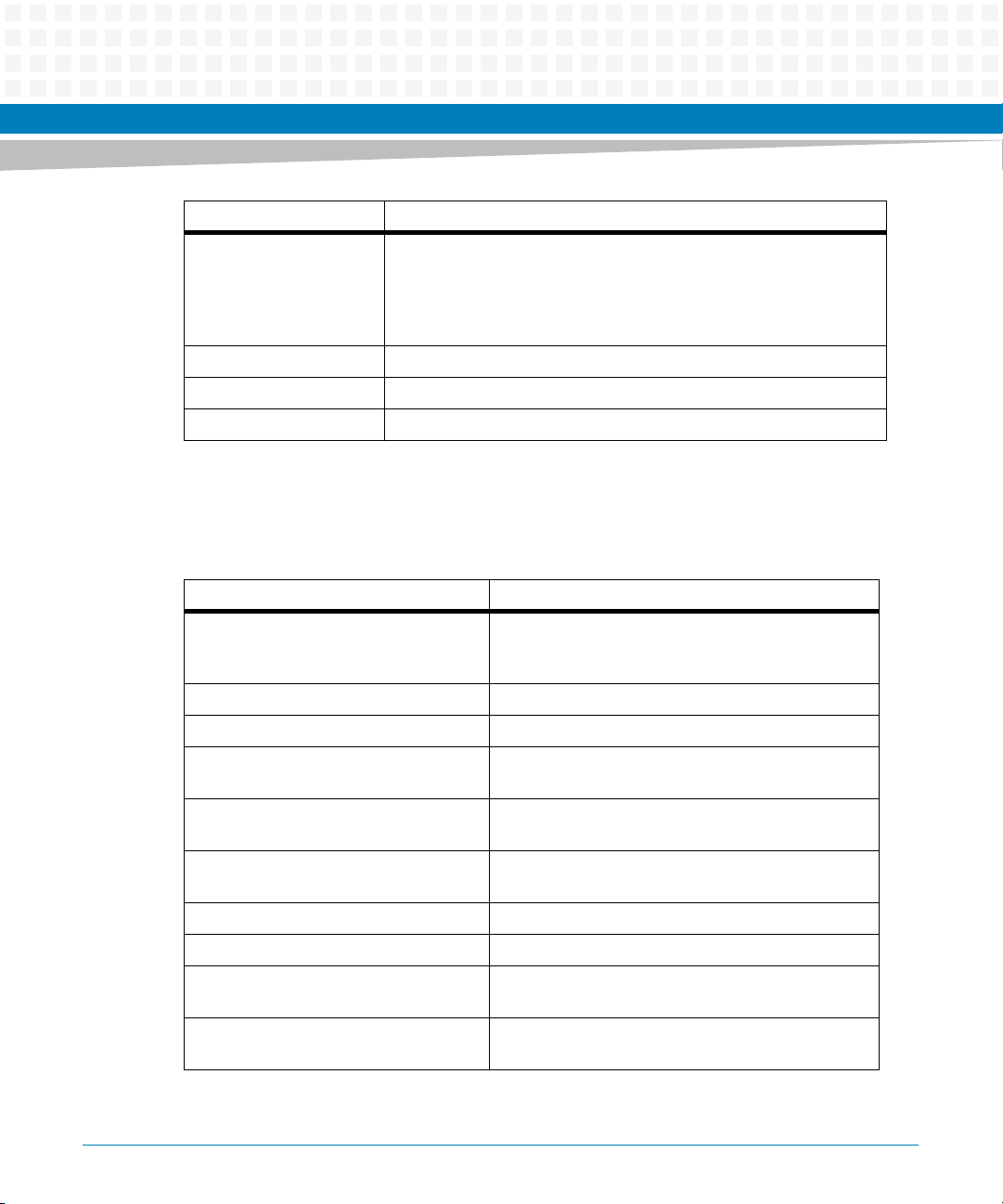
Conventions
The following table describes the conventions used throughout this manual.
About this Manual
to Intel server and client platforms that can improve virtualization
solutions. VT provides a foundation for widely-deployed
virtualization solutions and enables more robust hardware assisted
virtualization solution.
Notation Description
0x00000000 Typical notation for hexadecimal numbers (digits are
0 through F), for example used for addresses and
offsets
0b0000 Same for binary numbers (digits are 0 and 1)
bold Used to emphasize a word
Screen Used for on-screen output and code related elements
or commands in body text
Courier + Bold Used to characterize user input and to separate it
from system output
Reference Used for references and for table and figure
descriptions
File > Exit Notation for selecting a submenu
<text> Notation for variables and keys
[text] Notation for software buttons to click on the screen
and parameter description
... Repeated item for example node 1, node 2, ..., node
12
iVPX7225 RTM Installation and Use (6806800S35B)
13
Page 14
About this Manual
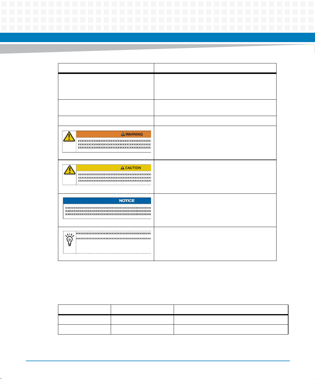
Notation Description
About this Manual
.
.
.
.. Ranges, for example: 0..4 means one of the integers
| Logical OR
Omission of information from example/command
that is not necessary at the time being
0,1,2,3, and 4 (used in registers)
Indicates a hazardous situation which, if not avoided,
could result in death or serious injury
Indicates a hazardous situation which, if not avoided,
may result in minor or moderate injury
Indicates a property damage message
No danger encountered. Pay attention to important
information
Summary of Changes
This manual has been revised and replaces all prior editions.
Part Number Publication Date Description
6806800S35A October 2013 Initial version
6806800S35B April 2015 Rebranded to Artesyn
14
iVPX7225 RTM Installation and Use (6806800S35B)
Page 15

Safety Notes
This section provides warnings that precede potentially dangerous procedures throughout
this manual. Instructions contained in the warnings must be followed during all phases of
operation, service, and repair of this equipment. You should also employ all other safety
precautions necessary for the operation of the equipment in your operating environment.
Failure to comply with these precautions or with specific warnings elsewhere in this manual
could result in personal injury or damage to the equipment.
Artesyn Embedded Technologies intends to provide all necessary information to install and
handle the product in this manual. Because of the complexity of this product and its various
uses, we do not guarantee that the given information is complete. If you need additional
information, ask your Artesyn Embedded Technologies representative.
This product is a Safety Extra Low Voltage (SELV) device designed to meet the EN60950-1
requirements for Information Technology Equipment. The use of the product in any other
application may require safety evaluation specific to that application.
Only personnel trained by Artesyn Embedded Technologies or persons qualified in electronics
or electrical engineering are authorized to install, remove or maintain the product. The
information given in this manual is meant to complete the knowledge of a specialist and must
not be used as replacement for qualified personnel.
Keep away from live circuits inside the equipment. Operating personnel must not remove
equipment covers. Only factory authorized service personnel or other qualified service
personnel is allowed to remove equipment covers for internal subassembly or component
replacement or any internal adjustment.
Do not install substitute parts or perform any unauthorized modification of the equipment or
the warranty may be voided. Contact your local Artesyn Embedded Technologies
representative for service and repair to make sure that all safety features are maintained.
Artesyn Embedded Technologies and our suppliers take significant steps to make sure that
there are no bent pins on the backplane or connector damage to the boards prior to leaving
the factory. Bent pins caused by improper installation or by inserting boards with damaged
connectors could void the Artesyn Embedded Technologies warranty for the backplane or
boards.
Use extreme caution when handling, testing, and adjusting this equipment and its
components around dangerous voltages that can cause injury or death.
iVPX7225 RTM Installation and Use (6806800S35B)
15
Page 16

Safety Notes
Installation
Damage of Circuits
Electrostatic discharge and incorrect installation and removal of the product can damage
circuits or shorten their life.
Before touching the product make sure that your are working in an ESD-safe environment or
wear an ESD wrist strap or ESD shoes. Hold the product by its edges and do not touch any
components or circuits.
Pin Damage
Forcing the module into the system may damage connector pins.
If the module hangs during insertion, pull it out and insert it again.
Damage of the Product and Additional Devices and Modules
Incorrect installation or removal of additional devices or modules damages the product or the
additional devices or modules.
Before installing or removing additional devices or modules, read the respective
documentation and use appropriate tools.
Operation
System Damage
During the course of handling, shipping, and assembly, pins, mounting screws, fans and other
items can become loose or damaged. Do not operate a damaged shelf, this can cause damage
to devices that interact with it.
System Overheating
Cooling Vents
Improper cooling can lead to blade and system damage and can void the manufacturer’s
warranty.
Always operate the blade in a configuration suitable for proper cooling. Do not obstruct the
ventilation of the system. Keep any fresh air intakes of the system enclosure completely clear.
Ensure that any fresh air supply is not mixed with hot exhaust from other devices. Ensure that
all system slots are populated with either blades, filler blades, or dummy blades.
16
iVPX7225 RTM Installation and Use (6806800S35B)
Page 17

Product Damage
High humidity and condensation on surfaces cause short circuits.
Do not operate the product outside the specified environmental limits. Make sure the product
is completely dry and there is no moisture on any surface before applying power.
Expansion and FRU Replacement
Product Damage
Bent pins or loose components can cause damage to the product, the backplane, or other
system components.
Carefully inspect the product and the backplane for both pin and component integrity before
installation.
Personal Injury
During operation, hot surfaces may be present on the heat sinks and components of the
product.
To prevent injury from hot surfaces do not touch any of the exposed components or heat sinks
on the product when handling. Use the handle and face plate when removing the product
from the enclosure.
Safety Notes
Hot Swap
Product Damage
Installing or removing the product while power is applied damages the product.
Power off the rack before installing or removing the product.
iVPX7225 RTM Installation and Use (6806800S35B)
17
Page 18

Safety Notes
18
iVPX7225 RTM Installation and Use (6806800S35B)
Page 19

Sicherheitshinweise
Dieses Kapitel enthält Hinweise, die potentiell gefährlichen Prozeduren innerhalb dieses
Handbuchs vorrangestellt sind. Beachten Sie unbedingt in allen Phasen des Betriebs, der
Wartung und der Reparatur des Systems die Anweisungen, die diesen Hinweisen enthalten
sind. Sie sollten außerdem alle anderen Vorsichtsmaßnahmen treffen, die für den Betrieb des
Systems innerhalb Ihrer Betriebsumgebung notwendig sind. Wenn Sie diese
Vorsichtsmaßnahmen oder Sicherheitshinweise, die an anderer Stelle diese Handbuchs
enthalten sind, nicht beachten, kann das Verletzungen oder Schäden am System zur Folge
haben.
Artesyn Embedded Technologies ist darauf bedacht, alle notwendigen Informationen zum
Einbau und zum Umgang mit dem System in diesem Handbuch bereit zu stellen. Da es sich
jedoch bei dem System um ein komplexes Produkt mit vielfältigen Einsatzmöglichkeiten
handelt, können wir die Vollständigkeit der im Handbuch enthaltenen Informationen nicht
garantieren. Falls Sie weitere Informationen benötigen sollten, wenden Sie sich bitte an die für
Sie zuständige Geschäftsstelle von Artesyn Embedded Technologies.
Das Produkt wurde entwickelt, um die Sicherheitsanforderungen für SELV Geräte nach der
Norm EN 60950-1 für informationstechnische Einrichtungen zu erfüllen. Die Verwendung des
Produkts in einer anderen Anwendung erfordert eine Sicherheitsüberprüfung für diese
spezifische Anwendung.
Einbau, Wartung und Betrieb dürfen nur von durch Artesyn Embedded Technologies
ausgebildetem oder im Bereich Elektronik oder Elektrotechnik qualifiziertem Personal
durchgeführt werden. Die in diesem Handbuch enthaltenen Informationen dienen
ausschließlich dazu, das Wissen von Fachpersonal zu ergänzen, können dieses jedoch nicht
ersetzen.
Halten Sie sich von stromführenden Leitungen innerhalb des Systems fern. Entfernen Sie auf
keinen Fall die Systemabdeckung. Nur werksseitig zugelassenes Wartungspersonal oder
anderweitig qualifiziertes Wartungspersonal darf die Systemabdeckung entfernen, um
Systemkomponenten zu ersetzen oder andere Anpassungen vorzunehmen.
Installieren Sie keine Ersatzteile oder führen Sie keine unerlaubten Veränderungen am System
durch, sonst verfällt die Garantie. Wenden Sie sich für Wartung oder Reparatur bitte an die für
Sie zuständige Geschäftsstelle von Artesyn Embedded Technologies. So stellen Sie sicher, dass
alle sicherheitsrelevanten Aspekte beachtet werden.
iVPX7225 RTM Installation and Use (6806800S35B)
19
Page 20

Sicherheitshinweise
Artesyn Embedded Technologies und unsere Zulieferer unternehmen größte Anstrengungen
um sicherzustellen, dass sich Pins und Stecker von Boards vor dem Verlassen der
Produktionsstätte in einwandfreiem Zustand befinden. Verbogene Pins, verursacht durch
fehlerhafte Installation oder durch Installation von Boards mit beschädigten Steckern kann die
durch Artesyn Embedded Technologies gewährte Garantie für Boards und Backplanes
erlöschen lassen.
Gehen Sie mit äußerster Vorsicht vor, bei der Handhabung, Prüfung und Einstellung dieser
Anlagen und deren Komponenten bezueglich gefährliche Spannungen, die zu Verletzungen
oder zum Tod führen koennen.
System Installation
Beschädigung von Schaltkreisen
Elektrostatische Entladung und unsachgemäßer Ein- und Ausbau des Produktes kann
Schaltkreise beschädigen oder ihre Lebensdauer verkürzen.
Bevor Sie das Produkt oder elektronische Komponenten berühren, vergewissern Sie sich, daß
Sie in einem ESD-geschützten Bereich arbeiten.
Schäden an Steckern
Wenn Sie das Modul mit Gewalt installieren, können die Anschlussstifte in den
Steckernbeschädigt werden. Falls sich das Modul während der Installation verkantet, ziehen
Sie es wieder heraus und führen Sie sie erneut ein
Beschädigung des Produktes und der Zusatzmodule
Fehlerhafter Ein- oder Ausbau von Zusatzmodulen führt zu Beschädigung des Produktes oder
der Zusatzmodule.
Lesen Sie deshalb vor dem Ein- oder Ausbau von Zusatzmodulen die Dokumentation und
benutzen Sie angemessenes Werkzeug.
Betrieb
Beschädigung des Systems
Beschädigung des Systems
Während des Transportes, Zusammenbaus und dem Umgang mit dem System können sich
Schrauben, Lüfter oder andere Teile lösen oder beschädigt werden.
20
iVPX7225 RTM Installation and Use (6806800S35B)
Page 21

Sicherheitshinweise
Nehmen Sie ein beschädigtes System nicht in Betrieb. Sonst können andere Einrichtungen, die
mit dem System kommunizieren, beschädigt werden.
Überhitzung des Systems
Lüftungsöffnungen
Unzureichende Lüftung kann Schäden an Blades und am System verursachen und die
Herstellergarantie ungültig werden lassen.
Arbeiten mit dem Baord sollten immer in einer eigens gekuehlten und konfigurierten
Umgebung erfolgen. Behindern Sie nicht die Belüftung des Systems. Achten Sie darauf, dass
alle Luftzugaenge des Systems komplett frei sind. Stellen Sie sicher, dass die zufuehrende Luft
nicht mit heissen Gasen von andered Geraeten vermischt wird. Stellen Sie ausserdem sicher,
das alle Steckplaetze im System entweder mit Boards, Filler blades oder Dummy Boards belegt
sind.
Beschädigung des Systems
Hohe Luftfeuchtigkeit und Kondensat auf den Oberflächen der Produkte kann zu
Kurzschlüssen führen.
Betreiben Sie die Produkte nur innerhalb der angegebenen Grenzwerte für die relative
Luftfeuchtigkeit und Temperatur und stellen Sie vor dem Einschalten des Stroms sicher, dass
sich auf den Produkten kein Kondensat befindet.
Erweiterung und FRU Austausch
Beschädigung des Produktes
Verbogene Stecker oder lose Teile können das Produkt, die Backplane oder andere
Systemkomponenten beschädigen.
Prüfen Sie das Produkt und die Backplane vor dem Einabau sorgfältig auf verbogene Stecker
und lose Teile.
Verletzungsgefahr
Während des Betriebs können Oberflächen an den Kühlkörpern oder anderen Komponenten
sehr heiß werden.
Um Verletzungen durch Verbrennung zu vermeiden, berühren Sie während der Arbeit keine
Komponenten oder Kühlkörper auf dem Produkt. Fassen Sie das Produkt an den Handles und
der Frontblende an, wenn Sie es aus dem System herausnehmen.
iVPX7225 RTM Installation and Use (6806800S35B)
21
Page 22

Sicherheitshinweise
Hot Swap
Beschädigung des Produktes
Wenn Sie das Produkt im laufenden Betrieb ein- oder ausbauen, kann es beschädigt werden.
Schalten Sie das Rack aus, bevor Sie das Produkt ein- oder ausbauen.
22
iVPX7225 RTM Installation and Use (6806800S35B)
Page 23

Introduction
1.1 Features
The iVPX7225 RTM provides access to the rear IO of the Artesyn 3U iVPX7225 module. The
following physical ports and switch banks are available via the iVPX7225 RTM:
Front Panel Access
One e-SATA port (Gen3)
One USB 2.0 Type A USB Receptacle
One COM Port (Male Micro-Mini DB9 (DTE); RS232/422/485)
One VGA Port (DE-15 Female)
Recessed Reset Switch
Chapter 1
PCB Planar Access
Two 1000BASE-T GbE ports (converted from 1000BASE-BX at the VPX backplane)
Two L-Shaped Internal SATA Ports (One Gen2; One Gen 3)
Two USB 2.0 Mini-B USB Receptacle
One COM Port (10-Pin header (DTE); RS232/422/485)
One Mini-DisplayPort
One IPMC Debug Port (Mini-B USB Physical Receptacle)
Eight PCH GPIO Control Signals
XMC Rear IO Access (VITA 46.9 3U X12d Pattern via Samtec Edge Rate Socket)
RS422/485 Termination Switch Bank
Write-Protect Override Switch Bank
iVPX7225 RTM Installation and Use (6806800S35B)
23
Page 24

Introduction
1.2 Standard Compliances
Table 1-1 Standard Compliances
Standard Description
FCC 47 CFR Part 15, Subpart B (US), Class A EMC requirements
ICES-003, Class A (non-residential)
VCCI CLASS A (Japan)
EN55022 Class A
EN55024
AS/NZS CISPR 22, Class A
1.3 Mechanical Data
The following table provides details about the dimensions and weight of the board.
Table 1-2 Mechanical Data
Feature Value
Form-factor Per VITA 46.10
Weight 0.16Kg (0.35 lbs)
24
iVPX7225 RTM Installation and Use (6806800S35B)
Page 25

1.4 Ordering Information
1.4.1 Supported Board Models
As of the printing date of this manual, this guide supports the board models listed below:
Table 1-3 Available Board Variants
Order Number Description
iVPX7225-RTM 3U VPX, AIR COOLED, RTM FOR iVPX7225,.8” FACEPLATE
iVPX7225-RTM-1 3U VPX, AIR COOLED, RTM FOR iVPX7225, 1” FACEPLATE
Table 1-4 Accessories
Order Number Description
Introduction
SERIAL-MINI-D (30-W2400E01A) Female-to-Male Micro-Mini DB9 to DB9 adapter cable
(~12 inches)
iVPX7225 RTM Installation and Use (6806800S35B)
25
Page 26

Introduction
1.5 Product Identification
The following graphic shows the location of the iVPX7225 RTM serial number label.
Figure 1-1 Serial Number Label Location
26
iVPX7225 RTM Installation and Use (6806800S35B)
Page 27

Hardware Preparation and Installation
2.1 Overview
This chapter describes:
Instructions for inspecting the board
Requirements that have to be observed when using the board
Installation and removal instructions
2.2 Unpacking and Inspecting the Board
Read all notices and cautions prior to unpacking the product.
Chapter 2
Damage of Circuits
Before touching the board or electronic components, make sure that you are working
in an ESD-safe environment.
Shipment Inspection
To inspect the shipment, perform the following steps.
1. Verify that you have received all items of your shipment which includes the
following but are not limited to;
Printed Quick Start Guide and Safety Note
iVPX7225 RTM
Any optional items ordered
iVPX7225 RTM Installation and Use (6806800S35B)
27
Page 28

Hardware Preparation and Installation
2. Check for damage. If damaged, report immediately to customer service.
3. Remove the desiccant bag shipped together with the board and dispose properly.
The board is thoroughly inspected before shipment. If damage occurred during transportation or any items are missing, please contact customer service immediately.
2.3 Environmental and Power Requirements
The following environmental and power requirements are applicable to the board.
2.3.1 Environmental Requirements
28
The environmental conditions must be tested and proven in the used system configuration.
These conditions refer to the surroundings of the board within the user environment.
Operating temperatures refer to the temperature of the air circulating around the board
and not to the component temperature.
To ensure that the operating conditions are met, forced air cooling is required within the
shelf environment.
The environmental values given in the table below only apply to the board without any
accessories. If installing accessories, their environmental requirements must also be
taken into account.
Product Damage
High humidity and condensation on the board surface causes short circuits.
Do not operate the board outside the specified environmental limits. Make sure the
board is completely dry and there is no moisture on any surface before applying power.
iVPX7225 RTM Installation and Use (6806800S35B)
Page 29

Table 2-1 Environmental Requirements
Environmental Parameter Air Cooled
Cooling Method Forced Air
Operating Temperature -40 °C to +71 °C
Storage Temperature -50 °C to +100 °C
Vibration Sine (10 min/Axis) 5G, 15 to 2000 HZ
Vibration Random (1 Hr/Axis) 0.04g2/Hz, 15 to 2000 Hz (8GRMS)
Shock 30g/11ms
Humidity to 95% RH non-condensing
1. Flat 15-1000Hz, -6db/octave 1000Hz – 2000Hz [MIL-STD 810F Figure 514.5C-17]
2.3.2 Power Requirements
Hardware Preparation and Installation
1
The following table contains the Power requirements:
Table 2-2 Power Requirements
Voltage Rail Minimum Power Typical Power Maximum Power
5V (VS3) 4.5W 6.2W 7.7W
3.3V 1.7W 2.7W 3.3W
Minimum Power: Representative of running Linux in a pure text mode (No X11/No GNOME), resting idle
the Linux login prompt. All externally powered peripherals idle.
Typical Power: Representative of running all front panel and planar I/O: 3-SATA (1@3Gb/s; 2@6Gb/s), 2Gigabit Ethernet, 2-USB 2.0, DP, VGA, Keyboard and COM. All externally powered peripherals active.
Maximum Power: Calculated worst-case power based upon device data sheets and is not expected to
be reached under normal operation. All peripherals are presumed to be externally powered.
iVPX7225 RTM Installation and Use (6806800S35B)
29
Page 30

Hardware Preparation and Installation
2.4 Installing the RTM
The iVPX7225 RTM does not support hot swap. Remove power to the rear slot or system before
installing the RTM.
Product Damage
Installing or removing the product while power is applied damages the product.
Power off the rack before installing or removing the product.
Product Damage
Only use injector handles for board insertion to avoid damage to the front panel and/or
PCB. Deformation of the front panel can cause an electrical short or other board
malfunction.
Board Malfunction
Switches marked as “reserved” might carry production-related functions and can cause
the board to malfunction if their setting is changed.
Do not change settings of switches marked as “reserved”. The setting of switches which
are not marked as “reserved” has to be checked and changed before board installation.
Installing the RTM
1. Turn off all equipment power and then disconnect the power cable from the power
source.
2. Remove the chassis cover as instructed in the equipment user's manual.
3. Remove the filler panel(s) from the appropriate card slot(s) at the rear of the chassis
(if the chassis has a rear card cage).
4. Slide the top and bottom edge of the transition module into the rear guide rails of
the chassis.
5. Ensure that the lever of the injector/ejector is in the outward position.
30
iVPX7225 RTM Installation and Use (6806800S35B)
Page 31

Hardware Preparation and Installation
6. Slide the transition module into the chassis until resistance is felt.
7. Move the injector/ejector lever in an inward direction.
8. Verify that the transition module is properly seated and secure it to the chassis
using the two screws located at the edges of the face plate.
9. Connect the appropriate cables to the transition module.
To remove the transition module from the chassis, reverse the procedure and press the red
locking tab to extract the board.
iVPX7225 RTM Installation and Use (6806800S35B)
31
Page 32

Hardware Preparation and Installation
32
iVPX7225 RTM Installation and Use (6806800S35B)
Page 33

Controls, LEDs and Connectors
3.1 Board Layout
The following graphic shows the location of the significant board components:
Figure 3-1 RTM Connectors
RP2 RP1 RP0
Chapter 3
LAN2
LAN1
Mini-DP
R-Term
eSATA COM 0
Reset Switch
USB1
COM 1
Super Cap
SATA2
SATA0
XMC_IO
WP_OR
USB 0
IPMC Debug
USB 2
VGA
PCH GPIO
iVPX7225 RTM Installation and Use (6806800S35B)
33
Page 34

Controls, LEDs and Connectors
eSATA
COM0
VGA
USB1
3.2 Front Panel
The front panel of the RTM provides the following interfaces:
One USB 2.0 Type A USB Receptacle
One VGA interface
One COM Port (Male Micro-Mini D B9 (DTE); RS232/422/485)
One e-SATA port (Gen3)
Recessed Reset Switch
Figure 3-2 Front Panel Connectors
3.3 Onboard LEDs
The onboard LEDs are listed below:
D1002 - LAN1 PHY up
D1102 - LAN2 PHY up
LAN1 Port - Integrated Steady Green LED (Link), Blinking Green LED (Activity)
LAN2 Port - Integrated Steady Green LED (Link), Blinking Green LED (Activity)
34
iVPX7225 RTM Installation and Use (6806800S35B)
Page 35

Controls, LEDs and Connectors
3.4 Backplane Connectors
The board provides the RP0, RP1 and RP2 backplane connectors.
3.4.1 RP0 Connector
The following table provides the pinout of the RP0 connector.
Table 3-1 RP0 Connector Pinout
Pin Wafer Type Row G Row F Row E Row D Row C Row B Row A
1Power
(VOID)
2 Power NC NC NC NC 3.3V VPX
3 Power 5.0 VPX
4 Single
Ended
5 Single
Ended
6 Single
Ended
7 Differential NC GND NC NC GND NC NC
8 Differential GND NC NC GND NC NC GND
9 Differential NC GND NC NC GND NC NC
10 Differential GND NC NC GND NC NC GND
11 Differential VBAT
12 Differential GND NC NC GND NC NC GND
13 Differential NC GND NC NC GND NC NC
14 Differential GND NC NC GND NC NC GND
NC NC NC NC 3.3V VPX
PWR
PWR
5.0 VPX
PWR
NC NC GND NC GND NC NVMRO
NC NC GND 3.3V AUX
NC NC GND NC GND NC NC
1
PWR
GND NC NC GND NC NC
5.0 VPX
PWR
NC 5.0 VPX
PWR
GND NC NC
VPX
3.3V VPX
PWR
3.3V VPX
PWR
5.0 VPX
PWR
3.3V VPX
PWR
3.3V VPX
PWR
5.0 VPX
PWR
15 Differential NC GND NC NC GND NC NC
16 Differential GND NC NC GND NC NC GND
iVPX7225 RTM Installation and Use (6806800S35B)
35
Page 36

Controls, LEDs and Connectors
1. The iVPX7225 PCH supports a battery-backed real-time clock with 256 bytes of battery-backed RAM. The PCH maintains the time
of the day and stores system data as long as the VBAT input remains above 2V (at the iVPX7225 PCH RTC input). In the event that the
system does not provide a voltage at VBAT, there is a diode protected 0.2F SuperCap (C214) onboard the iVPX7225 RTM to maintain
operation for short down times. The steady state current draw from the iVPX7225 at VBAT is 6 uA . In the event that VBAT is connected
to 3.3V_AUX at the backplane, the RTM SuperCap will discharge more quickly when 3.3V_AUX is removed. This is due to (SYSRESET)
terminations present on the VPX backplane. This could result in the loss of RTC and/or system data stored in the iVPX7225 PCH
battery-backed RAM. Refer to VITA 46 for additional information on the VBAT bussed signal.
3.4.2 RP1 Connector
The following table provides the pinout of the RP1 connector.
Table 3-2 RP1 Connector Pinout
Pin
Wafer Type Row G Row F Row E Row D Row C Row B Row A
1 Differential CRT BLUE GND CRT HSYNC CRT VSYNC GND CRT_CLK CRT DATA
2 Differential GND CRT GREEN CRT RED GND USB 0 N USB0 P GND
3 Differential IPMC1 SCL GND USB1 N USB1 P GND USB2 N USB2 P
4 Differential GND USB PEN Reserved GND USB 2
PEN
5 Differential IPMC1 SDA GND GPIO 0 GPIO 1 GND GPIO 2 GPIO 3
6 Differential GND GPIO 4 GPIO 5 GND GPIO 6 GPIO 7 GND
7 Differential NC GND ETH LANE 1
TX N
8 Differential GND ETH LANE 0
TX N
9 Differential SPI WP OR LGND COM0 RX
10 Differential GND COM1 RTS
TX N
11 Differential IPMC WP
OR L
GND ETH WP OR
ETH LANE 0
TX P
CTS N
COM1 TX P GND COM1
L
ETH LANE 1
TX P
GND ETH
COM0 RX
CTS P
PCIE SW
WP OR L
GND ETH LANE
LANE 0
RX N
GND COM0 TX
RX N
GND IPMC
USB OCP L GND
ETH LANE
1 RX N
ETH LANE
0 RX P
RTS N
COM1 RX
CTS P
DEBUG
RXD
1 RX P
GND
COM TX
RTS P
GND
IPMC
DEBUG
TXD
36
iVPX7225 RTM Installation and Use (6806800S35B)
Page 37

Controls, LEDs and Connectors
Table 3-2 RP1 Connector Pinout (continued)
Pin
Wafer Type Row G Row F Row E Row D Row C Row B Row A
12 Differential GND TX DIS VPD WP OR LGND SMB CLK SMB DATA GND
13 Differential NANDWP
OR L
14 Differential GND SATA P1 TX NSATA P1 TX P GND SATA P1
15 Differential FRAM WP
0R L
16 Differential GND DPD D0 N DPD D0 P GND DPD D1 NDPD D1 P GND
GND SATA P0 TX NSATA P0 TX PGND SATA P0
RX N
SATA P1
RX N
GND SATA P2 TX NSATA P2 TX P GND SATA P2
RX P
RX N
SATA P0
RX P
GND
SATA P2
RX P
3.4.3 RP2 Connector
The following table provides the pinout of the RP2 connector.
Table 3-3 RP2 Connector Pinout
Pin Wafer Type Row G Row F Row E Row D Row C Row B Row A
1 Differential DPD HPD GND DPD D2 N DPD D2 P GND DPD D3 N DPD D3 P
2 Differential GND DPD
DATA
3 Differential RTM
PRSNT L
GND P2 XMC
DPD CLK GND DPD AUX N DPD AUX P GND
12D 1 N
P2 XMC
12D 1 P
GND P2 XMC
12D 2 N
P2 XMC
12D 2 P
4 Differential GND P2 XMC
12D 3 N
5 Differential RTM FP
SW L
6 Differential GND P2 XMC
7 Differential RTM RST L GND P2 XMC
iVPX7225 RTM Installation and Use (6806800S35B)
GND P2 XMC
12D 7 N
P2 XMC
12D 3 P
12D 5 N
P2 XMC
12D 7 P
12D 9 N
GND P2 XMC
12D 4 N
P2 XMC
12D 5 P
GND P2 XMC
P2 XMC
12D 9 P
GND P2 XMC
12D 8 N
GND P2 XMC
P2 XMC
12D 4 P
12D 6 N
P2 XMC
12D 8 P
12D 10 N
GND
P2 XMC
12D 6 P
GND
P2 XMC
12D 10 P
37
Page 38

Controls, LEDs and Connectors
Table 3-3 RP2 Connector Pinout (continued)
Pin Wafer Type Row G Row F Row E Row D Row C Row B Row A
8 Differential GND P2 XMC
12D 11 N
P2 XMC
12D 11 P
GND P2 XMC
12D 12 N
P2 XMC
12D 12 P
GND
3.5 Front Panel Connectors
The following sections detail the available Front Panel connectors on the board:
3.5.1 P601 – SATA Port1 eSATA
Table 3-4 P601 – SATA Port1 eSATA Pinout
CAD P1 N 1 2 SATA P1 TX P
SATA P1 TX N 3 4 Ground
SATA P1 RX N 5 6 SATA P1 RX P
Ground 7
3.5.2 J1 - USB1Front Panel Type -A Receptacle
Table 3-5 J1 – USB1 Front Panel Type-A Receptacle Pinout
+5V 1 2 USB1 N
USB1 P 3 4 Ground
38
iVPX7225 RTM Installation and Use (6806800S35B)
Page 39

Controls, LEDs and Connectors
3.5.3 J7 - COM0 RS232/422/485 Front Panel Port
Table 3-6 J7 – COM0 RS232/422/485 Front Panel Port Pinout
NC 1 2 COM0 RX P
COM0 TX P 3 4 NC
Ground 5 6 NC
COM0 RTS/TX N 7 8 COM CTS/RX N
NC 9
3.5.4 J901 – Front Panel VGA DE-15 Female Port
Table 3-7 J901 –Front Panel VGA DE-15 Female Port Pinout
CRT RED 1 2 CRT GREEN
CRT BLUE 3 4 NC
Ground 5 6 Red GND
Green GND 7 8 Blue GND
+5V 9 10 Sync GND
NC 11 12 CRT DATA
CRT HSYNC 13 14 CRTVSYNC
CRT CLK 15
3.6 PCB Planar Access Ports
The following sections detail the PCB Planar Access Ports available on the board:
iVPX7225 RTM Installation and Use (6806800S35B)
39
Page 40

Controls, LEDs and Connectors
3.6.1 J101 – Planar Dual-Ganged Gigabit Ethernet Port
Table 3-8 J101 –Planar Dual-Ganged Gigabit Ethernet Port Pinout
iVPX7225 LAN
Port
LAN2 LANB
LAN1 LANA
Connector
Port
Dual Ganged
Connector Pin
9B 1 LAN 2 DA P
10B 2 LAN 2 DA N
7B 3 LAN 2 DB P
8B 4 LAN 2 DB N
5B 5 LAN 2 DC P
6B 6 LAN 2 DC N
3B 7 LAN 2 DD P
4B 8 LAN 2 DD N
9A 1 LAN 1 DA P
10A 2 LAN 1 DA N
7A 3 LAN 1 DB P
8A 4 LAN 1 DB N
5A 5 LAN 1 DC P
6A 6 LAN 1 DC N
3A 7 LAN 1 DD P
4A 8 LAN 1 DD N
RJ-45 Pin RJ-45 Signal
3.6.2 J4 - SATA Port0 L -Shaped Internal
Table 3-9 J4 – SATA Port0 L-Shaped Internal Pinout
CAD P0 N 1 2 SATA P0 TX P
SATA P0 TX N 3 4 Ground
40
iVPX7225 RTM Installation and Use (6806800S35B)
Page 41

Table 3-9 J4 – SATA Port0 L-Shaped Internal Pinout (continued)
SATA P0 RX N 5 6 SATA P0 RX P
Ground 7
3.6.3 J5 – SATA Port2 L-Shaped Internal
Table 3-10 J5 – SATA Port2 L-Shaped Internal Pinout
CAD P2 N 1 2 SATA P2 TX P
SATA P2 TX N 3 4 Ground
SATA P2 RX N 5 6 SATA P2 RX P
Ground 7
Controls, LEDs and Connectors
3.6.4 J3 - USB0 Mini-B Receptacle
Table 3-11 J3 – USB0 Mini-B Receptacle Pinout
+5V 1 2 USB0 N
USB0 P 3 4 NC
Ground 5
3.6.5 J2 - USB2 Mini-B Receptacle
Table 3-12 J2 – USB2 Mini-B Receptacle Pinout
+5V 1 2 USB2 N
USB2 P 3 4 NC
Ground 5
iVPX7225 RTM Installation and Use (6806800S35B)
41
Page 42

Controls, LEDs and Connectors
3.6.6 P701 - COM1 RS232/422/485 Header
Table 3-13 P701 - RS232/422/485 Header Pinout
NC 1 2 COM1_RX_P
COM1_TX_P 3 4 NC
Ground 5 6 NC
COM1_RTS/TX_N 7 8 COM1_CTS/RX_N
NC 9 10 NC
3.6.7 J801 – Mini Display Port Planar Connector
42
Table 3-14 J801 – Mini Display Port Planar Connector Pinout
Ground 1 2 DPD HPD
DPD D0 P 3 4 CAD DP
DPD D0 N 5 6 10 MegOhm Pull Down
Ground 7 8 Ground
DPD D1 P 9 10 DPD D3 P
DPD D1 N 11 12 DPD D3 N
Ground 13 14 Ground
DPD D2 P 15 16 DPD AUX P
DPD D2 N 17 18 DPD AUX N
Ground 19 20 +3.3V
iVPX7225 RTM Installation and Use (6806800S35B)
Page 43

Controls, LEDs and Connectors
3.6.8 J1201 - IPMC Debug Mini-B USB Physical Receptacle
Table 3-15 J1201 – IPMC Debug Mini-B USB Physical Receptacle Pinout
NC 1 2 Rx In
Tx Out 3 4 NC
Ground 5
3.6.9 P702 - PCH GPIO Header
Table 3-16 P702 - PCH GPIO Header Pinout
Ground 1 2 GPIO1 (PCH GPIO 22)
GPIO0 (PCH GPIO 17) 3 4 GPIO3 (PCH GPIO 7)
GPIO2 (PCH GPIO 6) 5 6 Ground
GPIO4 (PCH GPIO 68) 7 8 GPIO5 (PCH GPIO 69)
Ground 9 10 GPIO7 (PCH GPIO 71)
GPIO6 (PCH GPIO 70) 11 12 Reserved
Refer to the Intel Panther Point External Design Specification for voltage
levels and functionality. Each PCH_GPIO is pulled to +3.3V by a 10KOhm
resistor onboard the iVPX7225.
3.6.10 J1101 - P2 XMC J16 Differential I/O
Table 3-17 J1101 - P2 XMC J16 Differential I/O Pinout
Ground 1 2 Ground
P2 XMC 12D 1 N 3 4 P2 XMC 12D 7 N
P2 XMC 12D 1 P 5 6 P2 XMC 12D 7 P
iVPX7225 RTM Installation and Use (6806800S35B)
43
Page 44

Controls, LEDs and Connectors
Table 3-17 J1101 - P2 XMC J16 Differential I/O Pinout (continued)
Ground 7 8 Ground
P2 XMC 12D 2 N 9 10 P2 XMC 12D 8 N
P2 XMC 12D 2 P 11 12 P2 XMC 12D 8 P
Ground 13 14 Ground
P2 XMC 12D 3 N 15 16 P2 XMC 12D 9 N
P2 XMC 12D 3 P 17 18 P2 XMC 12D 9 P
Ground 19 20 Ground
P2 XMC 12D 4 N 21 22 P2 XMC 12D 10 N
P2 XMC 12D 4 P 23 24 P2 XMC 12D 10 P
Ground 25 26 Ground
P2 XMC 12D 5 N 27 28 P2 XMC 12D 11 N
P2 XMC 12D 5 P 29 30 P2 XMC 12D 11 P
Ground 31 32 Ground
P2 XMC 12D 6 N 33 34 P2 XMC 12D 12 N
P2 XMC 12D 6 P 35 36 P2 XMC 12D 12 P
Ground 37 38 Ground
Ground 39 40 Ground
3.7 Switch Banks
The following sections detail the available switches on the board:
44
iVPX7225 RTM Installation and Use (6806800S35B)
Page 45

Controls, LEDs and Connectors
3.7.1 S701 - RS422/485 Termination Switch Bank
Table 3-18 S701 - RS422/485 Termination Switch Bank
OFF (Default) ON
S701.1 No Termination 100ohm termination COM0
S701.2 Full Duplex RS485 Half-duplex
S701.3 Full Duplex RS485 Half-duplex
S701.4 Full Duplex RS485 Half-duplex COM1
S701.5 Full Duplex RS485 Half-duplex
S701.6 No Termination 100 ohm termination
3.7.2 S1101 - Write-Protect Override Switch Bank
Table 3-19 S1101 - Write-Protect Override Switch Bank
OFF (Default) ON
S1101.1 RTM Local VPD and IPMC FRU EEPROM
Not Write Protected
S1101.2 iVPX7225 VPD EEPROM Write Protect
Follows NVMRO Backplane Input.
May be Overridden by iVPX7225
Memory Write Protect Register at Offset
0x0B when NVMRO is LOW.
S1101.3 iVPX7225 SPI BootFlash Write Protect
Follows NVMRO Backplane Input.
May be Overridden by iVPX7225
Memory Write Protect Register at Offset
0x0B when NVMRO is LOW.
RTM Local VPD and IPMC FRU EEPROM Write
Protect Follows NVMRO Backplane Input
iVPX7225 VPD EEPROM Write Protected
Regardless of NVMRO Backplane Input
iVPX7225 SPI BootFlash Write Protected
Regardless of NVMRO Backplane Input
iVPX7225 RTM Installation and Use (6806800S35B)
45
Page 46

Controls, LEDs and Connectors
Table 3-19 S1101 - Write-Protect Override Switch Bank (continued)
OFF (Default) ON
S1101.4 iVPX7225 PCIE Switch EEPROM Write
Protect Follows NVMRO Backplane
Input.
May be Overridden by iVPX7225
Memory Write Protect Register at Offset
0x0B when NVMRO is LOW.
iVPX7225 PCIE Switch EEPROM Write
Protected Regardless of NVMRO Backplane
Input
S1101.5 iVPX7225 ETH controller EEPROM Write
Protect Follows NVMRO Backplane
Input.
May be Overridden by iVPX7225
Memory Write Protect Register at Offset
0x0B when NVMRO is LOW.
S1101.6 iVPX7225 IPMC SEL EEPROM Write
Protect Follows NVMRO Backplane
Input.
May be Overridden by iVPX7225
Memory Write Protect Register at Offset
0x0B when NVMRO is LOW.
S1101.7 iVPX7225 USB-NAND Flash Write
Protect Follows NVMRO Backplane
Input.
May be Overridden by iVPX7225
Memory Write Protect Register at Offset
0x0B when NVMRO is LOW.
S1101.8 iVPX7225 FRAM Write Protect Follows
NVMRO Backplane Input.
May be Overridden by iVPX7225
Memory Write Protect Register at Offset
0x0B when NVMRO is LOW.
For more information about Memory Write Protect Register, refer 6806800S11A-iVPX7225
Installation and Use manual.
iVPX7225 ETH Controller EEPROM Write
Protected Regardless of NVMRO Backplane
Input
iVPX7225 IPMC SEL EEPROM Write Protected
Regardless of NVMRO Backplane Input
iVPX7225 USB-NAND Flash Write Protected
Regardless of NVMRO Backplane Input
iVPX7225 FRAM Write Protected Regardless of
NVMRO Backplane Input
46
iVPX7225 RTM Installation and Use (6806800S35B)
Page 47

Functional Description
4.1 Block Diagram
The following figure shows the block diagram of iVP7225 RTM.
Figure 4-1 iVPX7225 RTM Block Diagram
Chapter 4
iVPX7225 RTM Installation and Use (6806800S35B)
47
Page 48

Functional Description
4.2 Ethernet Interfaces
The Artesyn iVPX7225 module provides two 1000BASE-BX ports that are routed to the VPX
backplane for operation as Ultra Thin Pipes per VITA 65 SLT3-PAY-2F2U-14.2.3 and SLT3-PAY1F1F2U-14.2.4 slot profiles.
Ethernet is implemented using an Intel 82580 Gigabit Ethernet controller onboard the
iVPX7225. PCH PCIe Port 0 (lanes 1-4, configured as x4) is routed to 82580. When accessed via
the RTM, in a non-switch backplane configuration, dual PHYs onboard the iVPX7225 RTM
convert these control plane interfaces to 1000BASE-T. These are accessible at the dual RJ-45
RTM planar connector, J101.
Because the Ethernet interface to the backplane is 1000Base-BX, the associated 1000BaseT ports on the RTM are fixed at 1000Mbit, and cannot auto-negotiate down to 10/100Mbit.
Figure 4-2 SLT3-PAY-2F2U-14.2.3 Slot Profile
Key
SE
P0/J0
Utility Plane
S
E
Diff
User Defined
P1/J1
Utility Plane
S
Diff
E
User Defined
48
P2/J2
Data Plane - 2 Fat Pipes
User Defined
Control Plane - 2 Ultra-Thin Pipes
User Defined
Key
iVPX7225 RTM Installation and Use (6806800S35B)
Page 49

Figure 4-3 SLT3-PAY-1F1F2U-14.2.4 Slot Profile
Key
SE
P0/J0
Utility Plane
User Defined
S
E
Diff
P1/J1
Data Plane - 1 Fat Pipe
Expansion Plane - 8 pairs
User Defined
Functional Description
Utility Plane
User Defined
4.3 SATA
The Artesyn iVPX7225 module provides two SATA Gen 3 (up to 6Gbit/s) ports and one SATA
Gen 2 (up to 3Gbit/s) port routed to the VPX backplane P1 connector and another SATA Gen 2
(up to 3Gbit/s) port routed to the XMC.
RTM planar SATA connector J5 supports iVPX7225 PCH SATA Port2 (Gen2). RTM Front panel eSATA connector supports PCH SATA Port1 (Gen2/Gen3). The RTM planar SATA connector J4
supports PCH SATA Port0 (Gen3).
4.4 USB
Control Plane - 2 Ultra-Thin Pipes
S
Diff
E
P2/J2
User Defined
Key
The iVPX7225 RTM provides three USB 2.0 ports routed to the VPX backplane P1 connector.
These correspond to iVPX7225 PCH USB Port0, Port1, and Port2. These interfaces can be
accessed via RTM.
iVPX7225 RTM Installation and Use (6806800S35B)
49
Page 50

Functional Description
RTM planar Mini-B USB receptacle J2 supports iVPX7225 PCH USB Port 2. RTM planar Mini-B
USB receptacle J3 supports iVPX7225 PCH USB Port0. RTM front panel Type-A USB receptacle
J1 supports iVPX7225 PCH USB Port1.
4.5 Serial COM
iVPX7225 provides two serial ports (both configurable as RS232/422/485) to the VPX
backplane.
The RTM front panel Male Micro-Mini DB9 (DTE) connector J7 provides access to COM0 and the
planar header P701 provides access to COM1 (DTE).
Table 4-1 COM0 (J7)/COM1 (P701) RS232/422/485 Functions
COM PIN RS232 Functions RS422/485 Functions
2RXRX-
3TXTX-
7 RTS TX+
8 CTS RX+
4.6 Video
Two video interfaces (one digital, one analog) are routed to the backplane from the iVPX7225.
The video interfaces can be accessed through the RTM.
4.6.1 Rear DisplayPort
The RTM planar mini-DisplayPort connector J801 supports Display Port natively, and can
support DVI or HDMI through the use of active DP ->DVI or DP->HDMI adapters. The RTM front
panel DE-15F connector (J901) provides the analog VGA output.
4.6.2 VGA
The RTM front panel DE-15F connector (J901) provides the analog VGA output.
50
iVPX7225 RTM Installation and Use (6806800S35B)
Page 51

4.7 IPMC Debug Port
Access to the iVPX7225 IPMC Controller Serial Debug interface is provided via J1201 on the
RTM planar. Although, physically, the IPMC Debug connector is a Mini-B USB Receptacle, this is
“not” a USB port. Refer to the connector pinout sections in Chapter 3, Controls, LEDs and
Connectors for the signal assignments. An adapter cable is necessary to make the appropriate
electrical connections between the RTM Mini-B USB physical connector and the physical
connector to the serial port in the end application (not provided).
4.8 GPIO
iVPX7225 RTM header P702 provides access to eight user-defined GPIO pins routed to the
iVPX7225 PCH via VPX user IO pins.
4.9 XMC Rear IO Access
Functional Description
iVPX7225 RTM connector J1101 is a Samtec Edge Rate Socket providing access to the 12
differential pairs defined by the VITA 46.9 3U X12d Pattern.
iVPX7225 RTM Installation and Use (6806800S35B)
51
Page 52

Functional Description
52
iVPX7225 RTM Installation and Use (6806800S35B)
Page 53

Appendix A
A Related Documentation
A.1 Artesyn Embedded Technologies - Embedded
Computing Documentation
The publications listed below are referenced in this manual. You can obtain electronic copies of
Artesyn Embedded Technologies - Embedded Computing publications by contacting your
local Artesyn sales office. For released products, you can also visit our Web site for the latest
copies of our product documentation.
1. Go to www.artesyn.com/computing/support/product/technical-documentation.php.
2. Under FILTER OPTIONS, click the Document types drop-down list box to select the type of
document you are looking for.
3. In the Search text box, type the product name and click GO.
Table A-1 Artesyn Embedded Technologies - Embedded Computing Publications
Document Title Publication Number
iVPX7225 Installation and Use 6806800S11A
iVPX7225 RTM Quick Start Guide 6806800S36A
iVPX7225 RTM Safety Notes Summary 6806800S37A
A.2 Related Specifications
For additional information, refer to the following table for related specifications. As an
additional help, a source for the listed document is provided. Please note that, while these
sources have been verified, the information is subject to change without notice.
Table A-2 Specifications
Organization Document
VITA VITA 46.10 Rear Transition Module for VPX
VITA VITA 46.11 system management for VPX draft Version 0.8
Intel Intelligent Platform Management Interface Specification Version 1.5
PICMG Hardware Platform Management IPM Controller Firmware Upgrade Specification
Rev 1.0
iVPX7225 RTM Installation and Use (6806800S35B)
53
Page 54

Related Documentation
54
iVPX7225 RTM Installation and Use (6806800S35B)
Page 55

Page 56

Artesyn Embedded Technologies, Artesyn and the Artesyn Embedded Technologies logo are trademarks and service marks of Artesyn Embedded Technologies, Inc.
All other product or service names are the property of their respective owners.
©
2015 Artesyn Embedded Technologies, Inc.
 Loading...