

Page 1

Touchstone®WTM652
Telephony Modem
User’s Guide
Get ready to experience the Internet’s express lane! Whether you’re checking out
streaming media, downloading new software, checking your email, or talking with
friends on the phone, the Touchstone WTM652 Telephony Modem brings it all to
you faster and more reliably. All while providing toll quality Voice over IP telephone
service and both wired and wireless connectivity. Some models even provide a Lithium-Ion battery backup to provide continued telephone service during power outages.
The Touchstone Telephony Modem provides four Ethernet connections for use as
the hub of your home/office Local Area Network (LAN). The Touchstone Telephony
Modem also provides 802.11b/g wireless connectivity for enhanced mobility and
versatility. In addition, the Touchstone Telephony Modem provides for up to two
separate lines of telephone service.
Installation is simple and your cable company will provide assistance to you for any
special requirements. The links below provide more detailed instructions.
Safety Requirements
Getting Started
Battery Installation and Removal (WTM652G only)
Installing and Connecting Your Telephony Modem
Configuring Your Wireless Connection
Configuring Your Ethernet Connection
Using the Telephony Modem
Troubleshooting
Glossary
Page 2

Export Regulations
This product may not be exported outside the U.S. and Canada without U.S. Department of Commerce, Bureau of Export Administration authorization. Any export or re-export by the purchaser, directly or indirectly, in contravention of U.S. Export Administration Regulation is prohibited.
Copyright © 2009 ARRIS. All rights reserved.
The information in this document is subject to change without notice. The statements, configurations, technical data, and recommendations in
this document are believed to be accurate and reliable, but are presented without express or implied warranty. Users must take full responsibility for their applications of any products specified in this document. The information in this document is proprietary to ARRIS.
ARRIS, Touchstone, and the ARRIS logo are trademarks or registered trademarks of ARRIS Group. All other trademarks and registered trademarks are the property of their respective holders.
Protected under one or more of the following U.S. patents: 7,031,453; 7,100,011. Other patents pending.
ARSVD01202
Release 6 Standard 1.0 March 2009
Page 3
Safety
Getting
Started
Battery
Installation
Installation
Wireless
Configuration
Ethernet
Configuration Usage Troubleshooting Glossary
Safety Requirements
ARRIS Telephony Modems comply with the applicable requirements for performance, construction, labeling, and information when used as outlined below:
CAUTION
Risk of shock
Mains voltages inside this unit. No user serviceable parts inside. Refer
service to qualified personnel only!
CAUTION
Potential equipment damage
Potential loss of service
Connecting the Telephony Modem to existing telephone wiring should
only be performed by a professional installer. Physical connections to
the previous telephone provider must be removed and the wiring must
be checked; there must not be any voltages. Cancellation of telephone
service is not adequate. Failure to do so may result in loss of service
and/or permanent damage to the Telephony Modem.
CAUTION
Risk of explosion
Replacing the battery with an incorrect type, heating a battery about
75°C, or incinerating a battery, can cause product failure and a risk of
fire or battery explosion. Dispose of used batteries according to the
instructions.
• The Telephony Modem is designed to be connected directly to a telephone.
• Connecting the Telephony Modem to the home’s existing telephone wiring
should only be performed by a professional installer.
• Do not use product near water (i.e. wet basement, bathtub, sink or near a
swimming pool, etc.), to avoid risk of electrocution.
Touchstone WTM652 Telephony Modem User’s Guide
3
Page 4

Safety
Getting
Started
Battery
Installation
Installation
Wireless
Configuration
Ethernet
Configuration Usage Troubleshooting Glossary
• Do not use spray cleaners or aerosols on the Telephony Modem.
• Avoid using and/or connecting the equipment during an electrical storm, to
avoid risk of electrocution.
• Do not use the telephone to report a gas leak in the vicinity of the leak.
• Do not locate the equipment within 6 feet (1.9 m) of a flame or ignition
source (i.e. heat registers, space heaters, fireplaces, etc.).
• Use only power supply and power cord included with the equipment.
• Equipment should be installed near the power outlet and should be easily
accessible.
• The shield of the coaxial cable must be connected to earth (grounded) at the
entrance to the building in accordance with applicable national electrical installation codes. In the U.S., this is required by NFPA 70 (National Electrical
Code) Article 820. In the European Union and in certain other countries,
CATV installation equipotential bonding requirements are specified in IEC
60728-11, Cable networks for television signals, sound signals and interac-
tive services, Part 11: Safety. This equipment is intended to be installed in
accordance with the requirements of IEC 60728-11 for safe operation.
If the equipment is to be installed in an area serviced by an IT power line
network, as is found in many areas of Norway, special attention should be
given that the installation is in accordance with IEC 60728-11, in particular
Annex B and Figure B.4.
• In areas of high surge events or poor grounding situations and areas prone
to lightning strikes, additional surge protection may be required (i.e.
PF11VNT3 from American Power Conversion) on the AC, RF, Ethernet and
Phone lines.
• When the Telephony Modem is connected to a local computer through Ethernet cables, the computer must be properly grounded to the building/residence AC ground network. All plug-in cards within the computer must be
properly installed and grounded to the computer frame per the manufacturer’s specifications.
Touchstone WTM652 Telephony Modem User’s Guide
4
Page 5

Safety
Getting
Started
Battery
Installation
Installation
Wireless
Configuration
Ethernet
Configuration Usage Troubleshooting Glossary
FCC Part 15
This equipment has been tested and found to comply with the requirements for a
Class B digital device under Part 15 of the Federal Communications Commission
(FCC) rules. These requirements are intended to provide reasonable protection
against harmful interference in a residential installation. This equipment generates,
uses and can radiate radio frequency energy and, if not installed and used in accordance with the instructions, may cause harmful interference to radio communications. However, there is no guarantee that interference will not occur in a
particular installation. If this equipment does cause harmful interference to radio or
television reception, which can be determined by turning the equipment off and on,
the user is encouraged to try to correct the interference by one or more of the following measures:
• Reorient or relocate the receiving antenna.
• Increase the separation between the equipment and receiver.
• Connect the equipment into an outlet on a circuit different from that to which
the receiver is connected.
• Consult the dealer or an experienced radio/TV technician for help.
Changes or modifications to this equipment not expressly approved by the party responsible for compliance could void the user’s authority to operate the equipment.
Touchstone WTM652 Telephony Modem User’s Guide
5
Page 6

Safety
Getting
Started
Battery
Installation
Installation
Wireless
Configuration
Ethernet
Configuration Usage Troubleshooting Glossary
European Compliance
This product complies with the provisions of the Electromagnetic Compatibility
(EMC) Directive (89/336/EEC), the Amending Directive (92/31/EEC), the Low Voltage Directive (73/23/EEC), and the CE Marking Directive (93/68/EEC). As such,
this product bears the CE marking in accordance with the above applicable Directive(s).
A copy of the Declaration of Conformity may be obtained from: ARRIS International, Inc., 3871 Lakefield Drive, Suite 300, Suwanee, GA 30024.
As indicated by this symbol, disposal of this product or battery
is governed by Directive 2002/96/EC of the European Parliament
and of the Council on waste electrical and electronic equipment
(WEEE). WEEE could potentially prove harmful to the environment; as such, upon disposal of the Telephony Modem the Directive requires that this product must not be disposed as
unsorted municipal waste, but rather collected separately and
disposed of in accordance with local WEEE ordinances.
This product complies with directive 2002/95/EC of the European
Parliament and of the Council of 27 January 2003 on the restriction
of the use of certain hazardous substances (RoHS) in electrical and
electronic equipment.
Touchstone WTM652 Telephony Modem User’s Guide
6
Page 7

Safety
Getting
Started
Battery
Installation
Installation
Wireless
Configuration
Ethernet
Configuration Usage Troubleshooting Glossary
Getting Started
About Your New Telephony Modem
The Touchstone WTM652 Telephony Modem is DOCSIS or Euro-DOCSIS compliant
with the following features:
• Speed: much faster than dialup or ISDN service
• Convenience: supports Ethernet and 802.11b/g wireless connections; both
can be used simultaneously
• Flexibility: provides two independent lines of telephone service as well as
high speed data
• Compatibility: supports tiered data services (if offered by your cable
company)
All WTM652 models provide:
• Wireless 802.11b/g connectivity
• Four Ethernet ports for connections to non-wireless devices
• Up to two lines of telephone service
Your WTM652 model is one of the following:
• WTM652A: DOCSIS compliant
• WTM652B: Euro-DOCSIS compliant
• WTM652G: DOCSIS compliant with Li-Ion backup battery
What’s in the Box?
Make sure you have the following items before proceeding. Call your cable company
for assistance if anything is missing.
• Telephony Modem
• Antenna
• Power Cord
Touchstone WTM652 Telephony Modem User’s Guide
7
Page 8
Safety
Getting
Started
Coax Cable
Battery
Installation
Installation
Wireless
Configuration
Ethernet
Configuration Usage Troubleshooting Glossary
• Quick Installation Guide
• Ethernet Cable
• Phone Cable
• CD-ROM
• Screws for wall-mounting the unit
• End User License Agreement
What’s on the CD?
The CD provides the following items:
• Quick Install Guide
• User’s Guide
Items You Need
If you are installing the Telephony Modem yourself, make sure you have the following items on hand before continuing:
• Telephony modem package: see What’s in the Box? for a list of items in
the package.
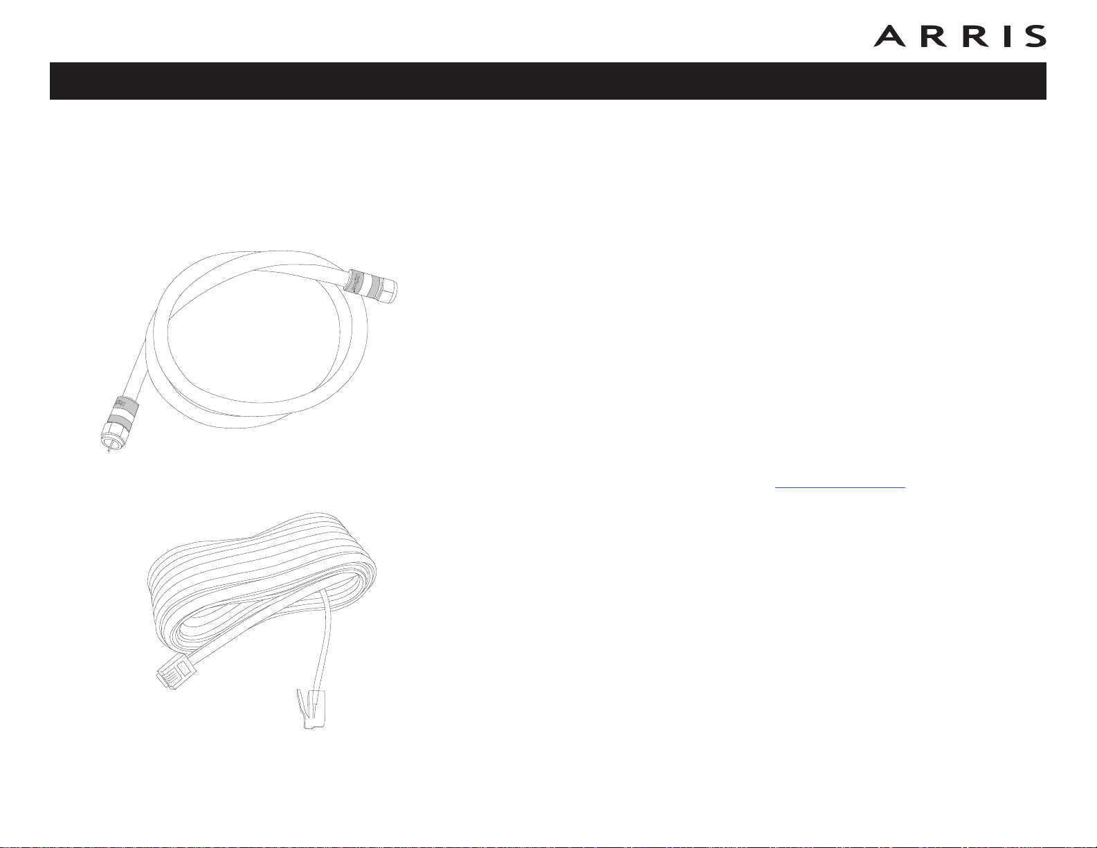
Phone Cable
• Coaxial cable (coax): as shown in the image to the left, this is a round
cable with a connector on each end. It is the same kind of wire used to connect to your television for cable TV. You can buy coax from any electronics
retailer and many discount stores; make sure it has connectors on both
ends. There are two types of connectors, slip-on and screw-on; the screwon connectors are best for use with your Telephony Modem. The coax should
be long enough to reach from your Telephony Modem to the nearest cable
outlet.
• Phone Cable: as shown in the image to the left, this is a standard phone
cable with standard phone connectors (RJ11 type) on both ends. You can
buy phone cables from any electronics retailer and many discount stores.
• Splitter (optional): provides an extra cable connection by splitting a single outlet into two. You may need a splitter if you have a TV already connected to the cable outlet that you want to use. You can buy a splitter from
Touchstone WTM652 Telephony Modem User’s Guide
8
Page 9

Safety
Getting
Started
Battery
Installation
Installation
Wireless
Configuration
Ethernet
Configuration Usage Troubleshooting Glossary
any electronics retailer and most discount stores; you may also need a short
piece of coax cable (with connectors); use it to connect the splitter to the
cable outlet and then connect the Telephony Modem and TV to the splitter.
Note: A splitter effectively cuts the signal in half and sends each half to its
two outputs. Using several splitters in a line may deteriorate the quality of
your television, telephone, and/or internet connection.
• Information packet: your cable company should furnish you with a packet
containing information about your service and how to set it up. Read this information carefully and contact your cable company if you have any questions.
Getting Service
Before trying to use your new Telephony Modem, contact your local cable company
to establish an Internet account and telephone service. When you call, have the
following information ready:
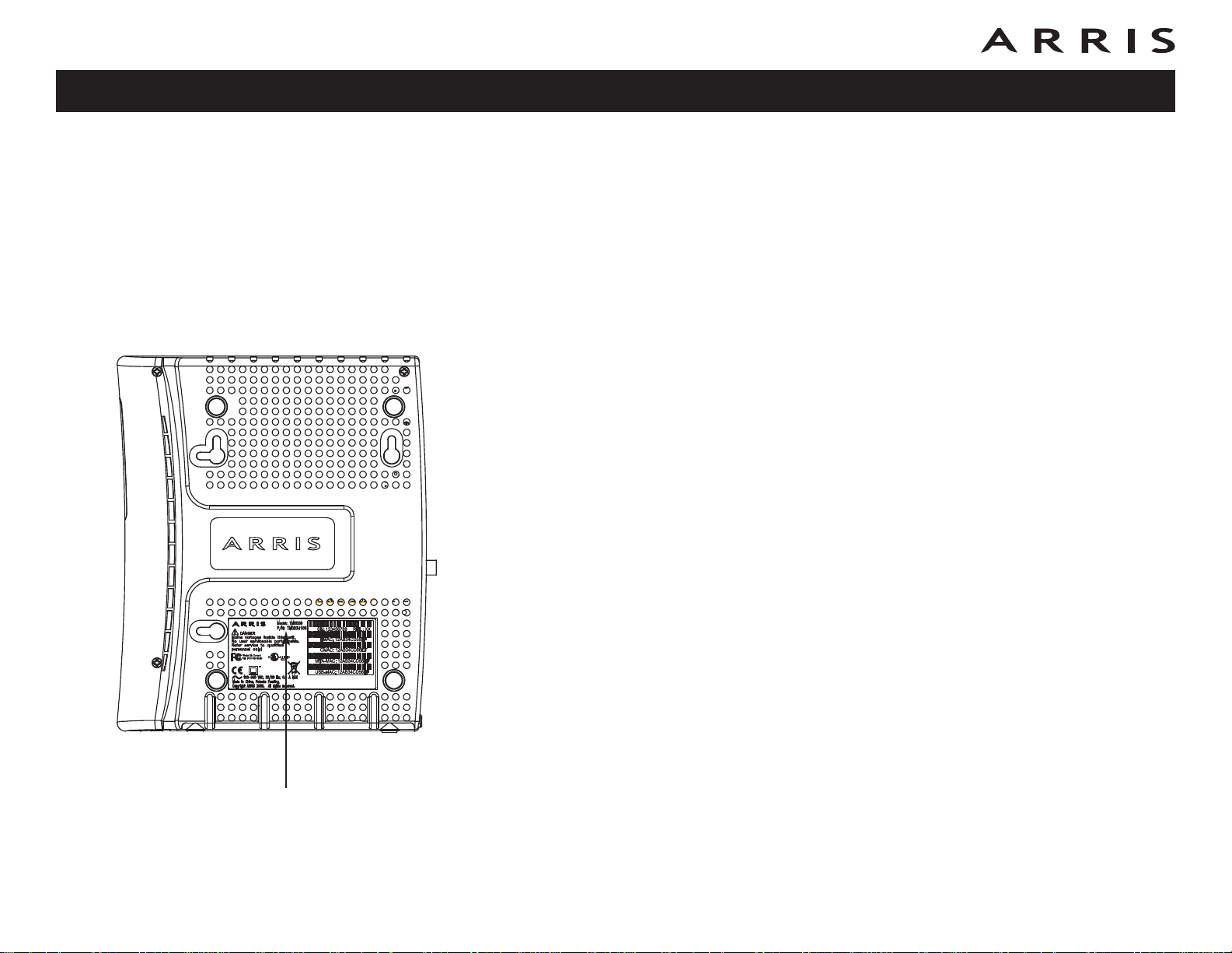
• the Telephony Modem serial number and cable MAC addresses of the unit
(printed on a sticker on the bottom of the Telephony Modem, as shown on
the next page)
• the model number of the Telephony Modem
If the Telephony Modem was provided by your cable company, they already have
the required information.
In addition, you should ask your cable company the following questions:
• Do you have any special system requirements or files that I need to download after I am connected?
• When can I start using my Telephony Modem?
• Do I need a user ID or password to access the Internet or my e-mail?
• Will my phone number(s) change?
• What new calling features will I have and how do I use them?
Touchstone WTM652 Telephony Modem User’s Guide
9
Page 10
FORHOME OR OFFICEUSE
Safety
Getting
Started
Battery
Installation
Installation
Wireless
Configuration
Ethernet
Configuration Usage Troubleshooting Glossary
System Requirements
The Touchstone Telephony Modem operates with most computers. The following
describes requirements for each operating system; see the documentation for your
system for details on enabling and configuring networking.
To use the Telephony Modem, you need DOCSIS high-speed Internet service from
your cable company.
Windows
Windows 98 SE (Second Edition), Windows ME, Windows 2000, Windows XP, or
Windows Vista. A supported Ethernet or wireless LAN connection must be available.
MacOS
System 7.5 to MacOS 9.2 (Open Transport recommended) or MacOS X. A supported
Ethernet or wireless LAN connection must be available.
Linux/other Unix
Hardware drivers, TCP/IP, and DHCP must be enabled in the kernel. A supported
Ethernet or wireless LAN connection must be available.
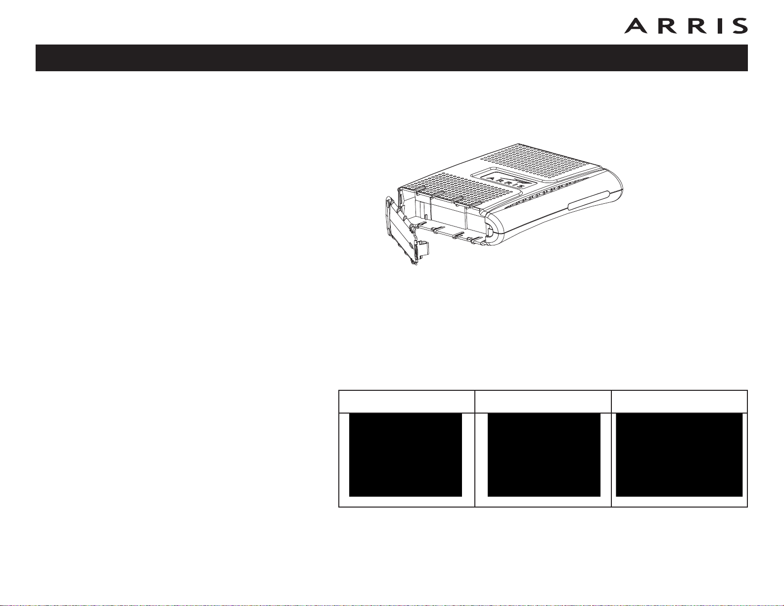
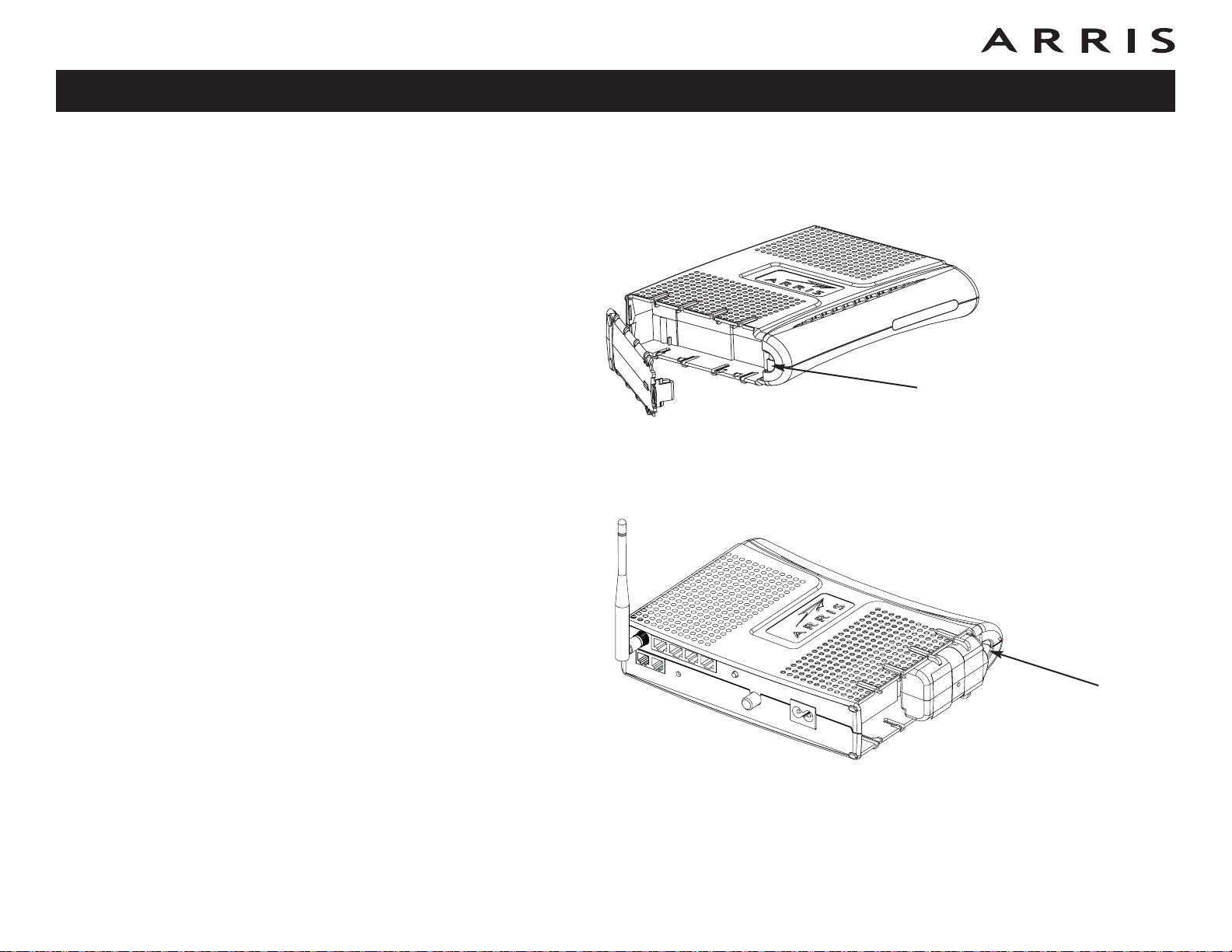
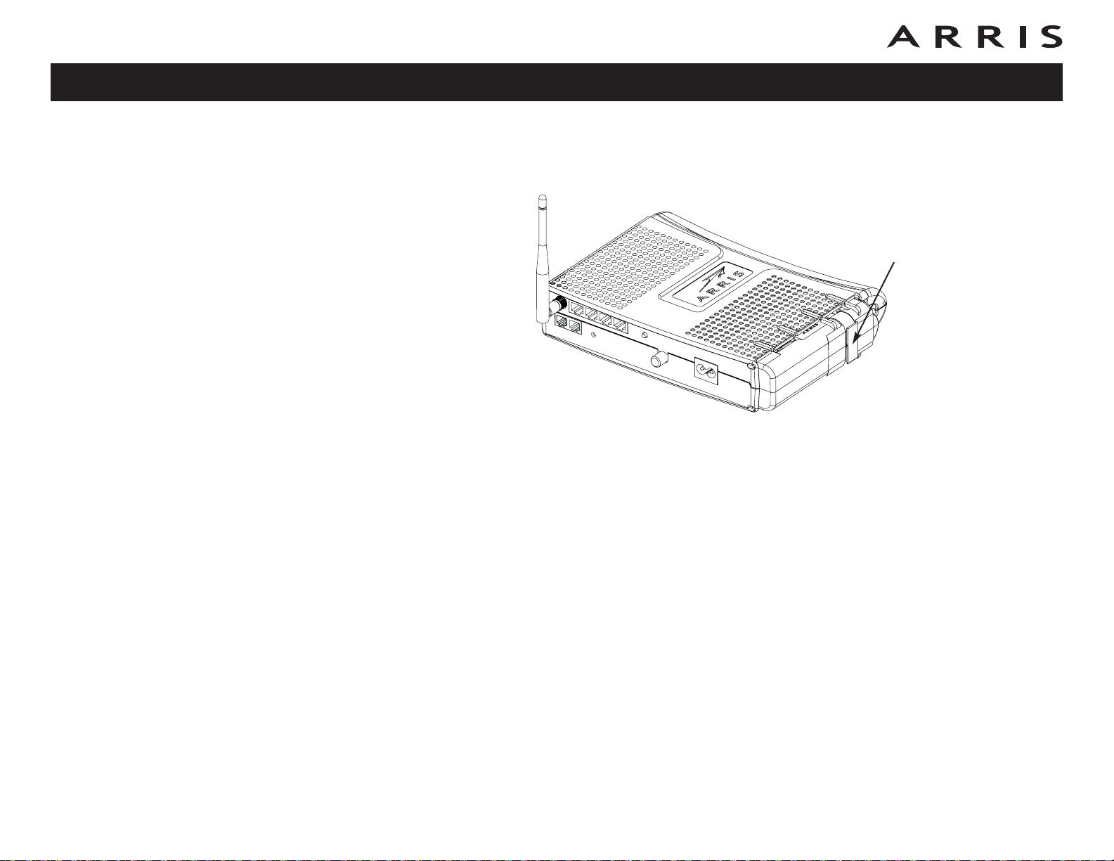
Model Number
About this Manual
This manual is written to cover all of the different WTM652 models. Your model
may or may not have all of the capabilities outlined in this manual. To determine
which model you have purchased, refer to the image at the left. The model number is on the label affixed to the Telephony Modem.
Touchstone WTM652 Telephony Modem User’s Guide
10
Page 11

Safety
Getting
Started
Battery
Installation
Installation
Wireless
Configuration
Ethernet
Configuration Usage Troubleshooting Glossary
Ethernet or Wireless?
There are two ways to connect your computer (or other equipment) to the Telephony Modem. The following will help you decide which is best for you:
Ethernet
Ethernet is a standard method of connecting two or more computers into a Local
Area Network (LAN). You can use the Ethernet connection if your computer has
built-in Ethernet hardware.
Note: To connect more than four computers to the WTM652 through the Eth-
ernet ports, you need an Ethernet hub (available at computer retailers).
The Telephony Modem package comes with one 6-foot (1.9m) Ethernet cable (the
connectors look like wide telephone connectors); you can purchase more cables if
necessary at a computer retailer. If you are connecting the Telephony Modem directly to a computer, or to an Ethernet hub with a cross-over switch, ask for Category 5 (CAT5) straight-through cable. If you are connecting the Telephony Modem
to an Ethernet hub without a crossover switch, ask for a Category 5 crossover cable.
Ethernet Cable
Wireless
The 802.11 wireless LAN standard allows one or more computers to access the
WTM652 using a wireless (radio) signal. You can use the wireless connection if your
computer has a built-in or aftermarket wireless card.
Note: To learn more about which wireless hardware works best with your com-
puter, see your computer dealer.
Both
If you have two or more computers, you can use Ethernet for up to four devices and
wireless for others. To connect five or more computers to the Ethernet ports, you
will need an Ethernet hub (available at computer retailers).
For more information about connecting two or more computers, contact your cable
service provider.
Touchstone WTM652 Telephony Modem User’s Guide
11
Page 12

Safety
Getting
Started
Battery
Installation
Installation
Wireless
Configuration
Ethernet
Configuration Usage Troubleshooting Glossary
What About Security?
Having a high-speed, always-on connection to the Internet requires a certain
amount of responsibility to other Internet users—including the need to maintain a
reasonably secure system. While no system is 100% secure, you can use the following tips to enhance your system’s security:
• Keep your operating system updated with the latest security patches. Run
the system update utility at least weekly.
• Keep your email program updated with the latest security patches. In addition, avoid opening email containing attachments, or opening files sent
through chat rooms, whenever possible.
• Install a virus checker and keep it updated.
• Avoid providing web or file-sharing services over your Telephony Modem.
Besides certain vulnerability problems, most cable companies prohibit running servers on consumer-level accounts and may suspend your account for
violating your terms of service.
• Use the cable company’s mail servers for sending email.
• Avoid using proxy
software unless you are certain that it is not open for
abuse by other Internet users (some are shipped open by default). Criminals can take advantage of open proxies to hide their identity when breaking into other computers or sending spam. If you have an open proxy, your
cable company may suspend your account to protect the rest of the network.
• If you use the wireless LAN, make sure you enable wireless security on the
Telephony Modem (for the same reasons that you should run only secured
proxies). See “Wireless Configuration” for help.
Touchstone WTM652 Telephony Modem User’s Guide
12
Page 13

Safety
Getting
Started
Battery
Installation
Installation
Wireless
Configuration
Ethernet
Configuration Usage Troubleshooting Glossary
Battery Installation and Removal
(WTM652G only)
Many Telephony Modem models support an optional Lithium-Ion backup battery.
The WTM652G supports the following battery models:
• Basic backup battery — provides up to 5 hours (black) or 8 hours (grey)
of backup time, depending on your Telephony Modem model and usage. It
may be light grey (recommended battery) or black.
• Extended backup battery — provides up to 12 hours of backup time, depending on model and usage. It has a strap between the battery guides.
• Maximum backup battery — provides up to 24 hours of backup time, depending on model and usage. It replaces the battery door, and increases the
height of the Telephony Modem by about 5/8 inch (16 mm).
Touchstone WTM652 Telephony Modem User’s Guide
13
Page 14
Safety
Getting
Started
Battery
Installation
Installation
Wireless
Configuration
Ethernet
Configuration Usage Troubleshooting Glossary
Your cable company may include a backup battery with your Telephony Modem.
You can order any of the batteries shown here at http://yourbroadbandstore.com/
Basic Backup Battery Installation
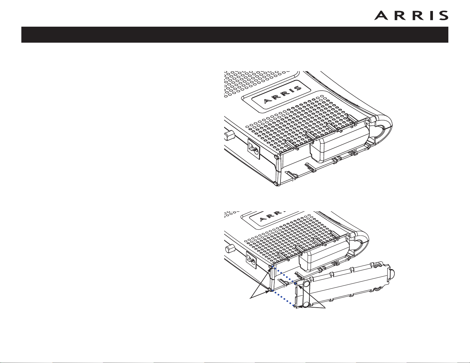
1 Pull back the battery door latch and remove the battery door. Set the door
aside.
2 Align the guides on the battery with the slots on the Telephony Modem as
shown below, and slide the battery into the bay.
Battery Slot
Battery Guide
Touchstone WTM652 Telephony Modem User’s Guide
14
Page 15
Safety
Getting
Started
Battery
Installation
Installation
Wireless
Configuration
Ethernet
Configuration Usage Troubleshooting Glossary
3 Push the battery pack into the bay until it seats into place. Push on the cen-
ter of the battery to avoid inserting the battery at an angle.
4 Replace the battery door: insert the hinge tabs in the receiver slots, and
close the door until the latch snaps into place.
Receiver
Slots
Hinge tabs
Touchstone WTM652 Telephony Modem User’s Guide
15
Page 16
Safety
Getting
Started
Battery
Installation
Installation
Wireless
Configuration
Ethernet
Configuration Usage Troubleshooting Glossary
Extended Backup Battery Installation
1 Pull back the battery door latch and remove the battery door. Set the door
aside.
2 Stand the Telephony Modem on its top, so the battery bay faces up.
3 Align the guides on the battery with the slots on the Telephony Modem as
shown below, and slide the battery into the bay.
Note: Batteries will not insert completely into the Telephony Modem if not
oriented correctly. The battery should slide into the bay without significant
force. Line up the slots in the battery bay with the guides on the battery
and apply even pressure on both ends of the battery.
WRONG WRONG RIGHT
Touchstone WTM652 Telephony Modem User’s Guide
16
Page 17
Safety
Getting
Started
Battery
Installation
Installation
Wireless
Configuration
Ethernet
Configuration Usage Troubleshooting Glossary
4 Replace the battery door: insert the hinge tabs in the receiver slots, and
close the door until the latch snaps into place.
Receiver
Slots
Hinge Tabs
Touchstone WTM652 Telephony Modem User’s Guide
17
Page 18
Safety
Getting
Started
Battery
Installation
Installation
Wireless
Configuration
Ethernet
Configuration Usage Troubleshooting Glossary
Maximum Backup Battery Installation
1 Pull back the battery door latch and remove the battery door. The Maximum
Backup battery replaces the door; store the door in a safe place.
2 Place the battery on a firm horizontal surface.
3 Position the Telephony Modem over the battery, aligning the slots on the
battery bay with the tabs on the battery. Push straight down on the Telephony Modem until the battery latch clicks into place.
Note: You may need to push down gently on the front of the Telephony
Modem to latch the battery into place.
Touchstone WTM652 Telephony Modem User’s Guide
18
Page 19
Safety
Getting
Started
Battery
Installation
Installation
Wireless
Configuration
Ethernet
Configuration Usage Troubleshooting Glossary
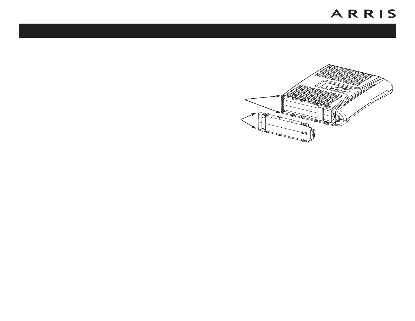
Basic and Extended Backup Battery Removal
1 Pull back the battery door latch and remove the battery door. Set the door
aside.
Latch End
2a Basic Backup battery removal: Insert a finger behind the battery tab where
shown below, and place your thumb over the other end of the battery. Pull
out gently until the battery disconnects and slides out of the bay.
Touchstone WTM652 Telephony Modem User’s Guide
Tab
19
Page 20
Safety
Getting
Started
Battery
Installation
Installation
Wireless
Configuration
Ethernet
Configuration Usage Troubleshooting Glossary
2b Extended Backup battery removal: Pull the strap until the battery discon-
nects and slides out of the bay.
Battery
Pull Strap
Touchstone WTM652 Telephony Modem User’s Guide
20
Page 21
Safety
Getting
Started
Battery
Installation
Installation
Wireless
Configuration
Ethernet
Configuration Usage Troubleshooting Glossary
Maximum Backup Battery Removal
1 Grasp the battery and pull back on the latch at the front of the battery.
2 Gently rock the battery out of the bay.
Touchstone WTM652 Telephony Modem User’s Guide
Latch
21
Page 22
Safety
Getting
Started
Battery
Installation
Installation
Wireless
Configuration
Ethernet
Configuration Usage Troubleshooting Glossary
Installing and Connecting Your
Telephony Modem
Before you start, make sure that:
• You have contacted your cable company and verified that they provide data
and telephone service using standard DOCSIS technology.
• You have all the items you need
• Cable, phone, and power outlets are available near the computer. If a cable
outlet is not conveniently located, your cable company can install a new one.
.
CAUTION
Risk of equipment damage
Only qualified installation technicians should connect the Telephony
Modem to house wiring. Incumbent telephone service must be physically disconnected at the outside interface box before making any
connections.
Touchstone WTM652 Telephony Modem User’s Guide
22
Page 23
Secure
WLAN
Safety
Getting
Started
Battery
Installation
Installation
Wireless
Configuration
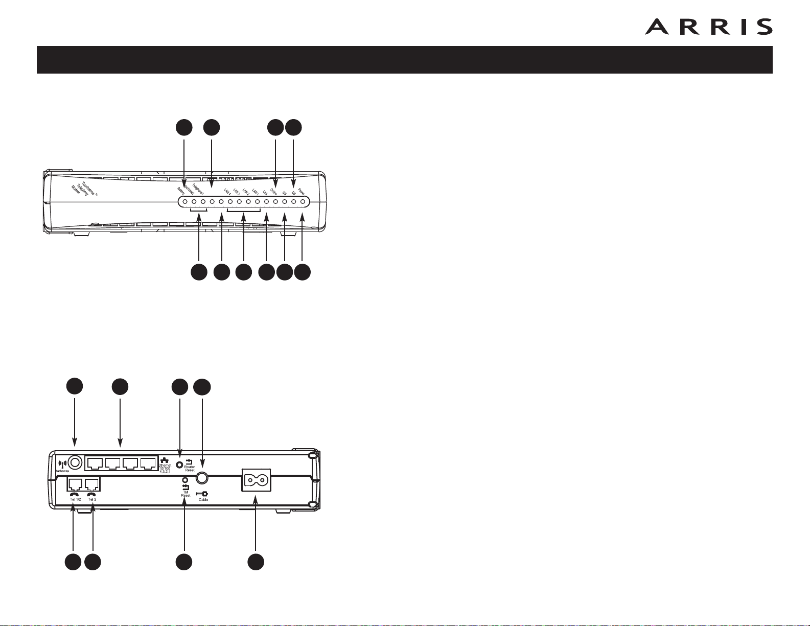
Front Panel
Ethernet
Configuration Usage Troubleshooting Glossary
D
B E
G
E
CA
G I
D F H J
The front of the Telephony Modem has the following indicators:
A Battery: (WTM652G only) indicates the battery status.
B Telephone 1/2: indicates the status of each telephone line.
C Secure: indicates Wireless Protected Setup (WPS) is active.
D WLAN: indicates the status of the wireless LAN.
E LAN 1–4: indicates the status of each Ethernet port.
F Link: indicates Ethernet or wireless connectivity between the Telephony-
Modem and computers.
G Online: indicates internet data transmission status.
H US: indicates upstream connectivity.
I DS: indicates downstream connectivity.
J Power: indicates whether AC power is available to the unit.
Rear Panel
The rear of the Telephony Modem has the following connectors and controls:
A Tel 1 (A/B models): connector for the first phone line.
Tel 1/2 (G models): connector for the first phone line (or both lines of a
2-line phone).
ACB
B Tel 2: connector for the second phone line.
C Antenna: connector for the wireless antenna.
D Ethernet: for use with a computer LAN port.
E Router Reset button: resets the Ethernet and wireless ports without af-
fecting telephony service.
F TM Reset button: resets the Telephony Modem as if you power cycled the
unit. Use a pointed non-metallic object to press this button.
G Cable: connector for the coaxial cable.
F
H
H Power: connector for the power cord.
Touchstone WTM652 Telephony Modem User’s Guide
23
Page 24

Safety
Getting
Started
Battery
Installation
Installation
Wireless
Configuration
Ethernet
Configuration Usage Troubleshooting Glossary
Selecting an Installation Location
There are a number of factors to consider when choosing a location to install your
Telephony Modem:
• Is an AC outlet available nearby? For best results, the outlet should not be
switched and should be close enough to the Telephony Modem that extension cords are not required.
• Is a cable jack available? For best performance, keep the number of splitters between the jack and cable drop to a minimum. Each splitter attenuates
(reduces) the signal available to the Telephony Modem. A large number of
splitters can slow down the Internet connection and even affect your telephone service.
• Can you easily run cables between the Telephony Modem’s location and the
phones?
• If you are connecting devices to the Ethernet ports, can you easily run cables between the Telephony Modem’s location and those devices?
• If you want to mount the Telephony Modem on a wall, does the location provide a solid surface for secure attachment? For best results when mounting
the Telephony Modem on drywall, position the Telephony Modem so at least
one of the screws are fastened to a stud. This may prevent the Telephony
Modem from pulling out of the wall in the future.
• If you want to install the Telephony Modem on a desktop, is there enough
space on either side to keep the vents clear? Blocking the vents may cause
overheating.
• How close are your wireless devices? The Telephony Modem wireless connection range is typically 100–200 feet (30m–65m). A number of factors can affect connection range, as described below.
Touchstone WTM652 Telephony Modem User’s Guide
24
Page 25

Safety
Getting
Started
Battery
Installation
Installation
Wireless
Configuration
Ethernet
Configuration Usage Troubleshooting Glossary
Factors Affecting Wireless Range
A number of factors can affect the usable range for wireless connections.
Increases range: • Raising the antenna above the devices (for example,
installing the Telephony Modem in the upper floor of a
multi-story dwelling or using an aftermarket omnidirectional antenna)
• Using an aftermarket directional antenna (increases
range in one direction while decreasing range in other
directions)
• Adding wireless hubs in a bridge (WDS) network
Decreases range: • Lowering the antenna below the devices (for example,
installing the Telephony Modem in a basement)
• Removing the antenna
• Metal or concrete walls between the Telephony Modem
and other devices
• Large metal appliances, aquariums, or metal cabinets
between the Telephony Modem and other devices
• Interference and RF noise (2.4 GHz wireless phones,
microwave ovens, or other wireless networks)
Note that decreasing the range of your wireless network may be beneficial, as long
as the decreased range is sufficient for your needs. By limiting your network’s
range, you reduce interference with other networks and make it harder for unwanted users to find and connect to your network.
Touchstone WTM652 Telephony Modem User’s Guide
25
Page 26

Safety
Getting
Started
Battery
Installation
Installation
Wireless
Configuration
Ethernet
Configuration Usage Troubleshooting Glossary
Mounting the Telephony Modem
You can either mount the Telephony Modem on a wall or place it on a desktop.
For wall-mount applications, you can mount the Telephony Modem with the indicators facing upward (vertical) or to the side (horizontal).
Tools and Materials
Step 1
Step 3
Step 2
Step 4
For wall-mounted installations, make sure you have the following tools and materials before proceeding:
• for mounting on drywall: Two 1/4” (6mm) drywall anchors and a drill with
1/4” (6mm) bit (not included)
• for mounting on plywood or studs: two #6 x 1.5” (38.1 mm) self tapping
screws (included)
• screwdriver (flat-blade or Phillips, depending on what kind of screws you
use)
• wall-mount template (included)
• transparent tape (for temporarily securing the mounting template to the
wall)
Wall-mounting instructions
1 Position the mounting template on the surface where you intend to mount
the Telephony Modem and secure in place with transparent tape.
2 Drill holes through the template in the specified locations for the mounting
screws. After drilling holes, remove the template from the surface.
3 If using drywall anchors, set them into the wall. Then, drive the screws into
the wall leaving a gap of about 1/8” (3 mm) between the screw head and
the wall. If not using anchors, just drive the screws.
4 Orient the Telephony Modem with the indicator lights facing up or right, as
desired. Slip both mounting slots (in the back of the Telephony Modem) over
the screws, then slide the case down until the narrow end of the keyhole slot
contacts the screw shaft.
5 Proceed to Connecting the Telephony Modem
.
Touchstone WTM652 Telephony Modem User’s Guide
26
Page 27

Safety
Getting
Started
Battery
Installation
Installation
Wireless
Configuration
Desktop mounting instructions
1 Position the Telephony Modem so that:
air flows freely around it
the back faces the nearest wall
it will not fall to the floor if bumped or moved
Ethernet
Configuration Usage Troubleshooting Glossary
ACB
D
2 Proceed to Connecting the Telephony Modem
G
E
F
H
Connecting the Telephony Modem
WARNING: Connecting the Telephony Modem to the home’s existing telephone wiring should only be performed by a professional installer. Physical connections to the previous telephone provider must be removed and
the wiring must be checked; there must not be any voltages. Cancellation
of telephone service is not adequate. Failure to do so may result in loss of
service and/or permanent damage to the Telephony Modem.
1 Thread the antenna onto the Antenna connector on the back of the Telepho-
ny Modem (C). Tighten only by hand. Turn the antenna so that it points
straight up, if possible.
2 Connect one end of the coax cable to the cable outlet or splitter, and the
other end to the Telephony Modem’s Cable connector (G). Tighten the connections by hand, then tighten an additional 1/8 turn with a wrench.
Note: For best performance, use high-quality coax cable and minimize or
eliminate splitters between the cable jack and the Telephony Modem.
3 Insert the plug from the power cord into the Power connector on the back
of the Telephony Modem (H) and insert the power cord into a convenient AC
outlet.
The Power light on the front of the Telephony Modem lights up, then flashes
once (refer to the LED table on page 44). See Troubleshooting
light does not turn on.
.
if the Power
4 Connect one end of the Ethernet cable to any Ethernet port on the back of
the Telephony Modem, (D) and the other end to the Ethernet port on a computer, hub, or broadband router.
Touchstone WTM652 Telephony Modem User’s Guide
27
Page 28

Safety
Getting
Started
Battery
Installation
Installation
Wireless
Configuration
Ethernet
Configuration Usage Troubleshooting Glossary
Note: If you are connecting to a computer, use the Ethernet cable included
in the Telephony Modem package.
5 Connect one end of the telephone cable to the telephone port on the back
of the Telephony Modem (A or B). Connect the other end to the telephone.
Touchstone WTM652 Telephony Modem User’s Guide
28
Page 29

Safety
Getting
Started
Battery
Installation
Installation
Wireless
Configuration
Ethernet
Configuration Usage Troubleshooting Glossary
Configuring Your Wireless Connection
The WTM652 ships with a basic factory default configuration that should allow you
to immediately access the Internet with a wireless connection. If your computer is
equipped with a 802.11b/g wireless LAN card, you may wish to configure the
WTM652 wireless settings. At a minimum, ARRIS suggests that you configure security settings.
Requirements
Make sure you have the following before attempting to configure your Ethernet connection:
• Computer with:
— Ethernet interface or wireless interface
— Ethernet cable, if using Ethernet interface (supplied)
• Web browser
Configuration Basics
The WTM652 uses a web-based interface to configure wireless settings. The following screen shows the various components of the interface.
1
2
3
1 Access bar: Shows the WTM652 connection status and provides the follow-
ing links:
• Home — returns to the Status page (shown above) from any screen.
• Help — displays help for the current screen.
• Login/Logout — allows access to screens other than the Status screen.
2 Navigation menu: Select any of the items in this list to display an associated
submenu. Selecting submenu items displays the associated screen. If you
are not logged in, the WTM652 displays the login screen before allowing you
to proceed.
3 Display area: Enter or view configuration information in this area. A ? link
may be available to explain the purpose of the screen or individual items on
the screen.
Touchstone WTM652 Telephony Modem User’s Guide
29
Page 30

Safety
Getting
Started
Battery
Installation
Installation
Wireless
Configuration
Ethernet
Configuration Usage Troubleshooting Glossary
Accessing the Configuration Interface
Follow these steps to access the configuration interface. You should have already set
up the WTM652 as described in Installing and Connecting Your Telephony Modem.
1 Use the connection utility for your operating system to connect to the wire-
less LAN arris54g (this is the Telephony Modem’s factory default SSID).
2 In your web browser, open the page http://192.168.2.1/ to display the
Status screen:
Touchstone WTM652 Telephony Modem User’s Guide
30
Page 31

Safety
Getting
Started
Battery
Installation
Installation
Wireless
Configuration
Ethernet
Configuration Usage Troubleshooting Glossary
3 Click the Login link in the Access bar to display the Login screen:
Note: The Telephony Modem ships with no password configured. When you
log in for the first time, leave the Password field blank.
4 Click the Submit button to return to the Status screen.
Note: The Access bar should now show Logout in place of Login.
5 Proceed to Configuring System Settings
.
Touchstone WTM652 Telephony Modem User’s Guide
31
Page 32

Safety
Getting
Started
Battery
Installation
Installation
Wireless
Configuration
Ethernet
Configuration Usage Troubleshooting Glossary
Configuring System Settings
1 Click the Utilities link (at the bottom of the Navigation menu) to open the
Utilities menu, then click System Settings to access the System Settings
screen:
2 Make changes as follows:
• Enter Current Password: If you have already created a password, and
you want to change settings on this screen, enter the password here.
• Enter New Password: Enter a password that you will remember but is
not easy to guess.
• Confirm new Password: Enter the same password again.
Touchstone WTM652 Telephony Modem User’s Guide
32
Page 33

Safety
Getting
Started
Battery
Installation
Installation
Wireless
Configuration
Ethernet
Configuration Usage Troubleshooting Glossary
• Time Zone: Select the proper time zone for your location. The Tele-
phony Modem uses an Internet time server to set its internal clock.
3 Scroll down to the bottom of the page and click the Save button. If you are
prompted to log in again, type your new password and click the Submit
button.
4 Proceed to Setting Up Your WAN Connection
.
Setting Up Your WAN Connection
Follow these steps to set up your WAN connection.
1 Click the WAN Setup link in the navigation menu, then click Connection Type.
The Connection Type screen appears:
2 Choose the correct connection type in the Connection Type screen. Most ca-
ble companies require the Dynamic connection type. If your cable company
requires a different connection type, you should have an information sheet
that shows the proper connection type to select and other information needed to set up the connection.
Touchstone WTM652 Telephony Modem User’s Guide
33
Page 34

Safety
Getting
Started
Battery
Installation
Installation
Wireless
Configuration
Ethernet
Configuration Usage Troubleshooting Glossary
3 Click the Next button at the bottom of the screen (you may have to scroll
down in the browser to see the Next button). The Telephony Modem displays a screen showing further settings for your connection type. Follow the
appropriate link for your connection type:
• Dynamic
• Static
• PPPoE
• L2TP
Dynamic
a. Fill in the Host Name field, using any name you want.
b. If you need to clone your computer’s MAC address, click the Change WAN
MAC Address link and proceed to Setting the MAC Address
.
c. Click the Save button.
d. Proceed to Configuring the LAN Channel and Name
.
Touchstone WTM652 Telephony Modem User’s Guide
34
Page 35

Safety
Getting
Started
Battery
Installation
Installation
Wireless
Configuration
Ethernet
Configuration Usage Troubleshooting Glossary
Static
a. Fill in the IP Address, Subnet Mask, and ISP Gateway address fields with the
information provided by your cable company.
b. If you need to enter DNS settings, click the link and proceed to Setting Up
DNS.
c. Click the Save button.
d. Proceed to Configuring the LAN Channel and Name.
Touchstone WTM652 Telephony Modem User’s Guide
35
Page 36

Safety
Getting
Started
Battery
Installation
Installation
Wireless
Configuration
Ethernet
Configuration Usage Troubleshooting Glossary
PPPoE
a. Fill in the User Name and Password fields with the information provided
by your cable company. Enter the password a second time in the Retype
Password field.
b. If you need to change the MTU size or fill in the Service Name, enter the in-
formation as specified by your cable company.
c. Click the Save button.
d. Proceed to Configuring the LAN Channel and Name
.
Touchstone WTM652 Telephony Modem User’s Guide
36
Page 37

Safety
Getting
Started
Battery
Installation
Installation
Wireless
Configuration
Ethernet
Configuration Usage Troubleshooting Glossary
L2TP
a. Fill in the L2TP Account, L2TP Password, Host Name, and Service IP
Address fields with the information provided by your cable company. Enter
the password a second time in the Retype Password field.
b. If you need to enter a static IP address and subnet mask, enter the infor-
mation as specified by your cable company. Otherwise, select “Get Dynamically from ISP.”
c. If you need to enter DNS settings, click the link and proceed to Setting Up
DNS.
d. Click the Save button.
e. Proceed to Configuring the LAN Channel and Name
.
Touchstone WTM652 Telephony Modem User’s Guide
37
Page 38

Safety
Getting
Started
Battery
Installation
Installation
Wireless
Configuration
Ethernet
Configuration Usage Troubleshooting Glossary
Setting Up DNS
Follow these steps to set up DNS.
1 From the current Connection Type screen, click the “Set Up DNS” link.
The DNS screen appears:
2 If your cable company has provided you with the IP addresses for their DNS
servers, enter the IP addresses in the DNS Address and Secondary DNS Address fields.
3 If you have not received DNS server information, check Automatic from
ISP.
4 Click the Save button to return to the Status screen.
5 Proceed to Configuring the LAN Channel and Name
.
Touchstone WTM652 Telephony Modem User’s Guide
38
Page 39

Safety
Getting
Started
Battery
Installation
Installation
Wireless
Configuration
Ethernet
Configuration Usage Troubleshooting Glossary
Configuring the LAN Channel and Name
1 Click the Wireless Setup link to open the Wireless menu, then click the Chan-
nel and SSID link to open the Channel and SSID screen:
2 Make the following changes to this screen as desired:
• Wireless Channel: Use the default shown in most cases. You may need
to change the channel if neighbors have wireless routers, or if you lose
your connection while using certain remote telephones.
• SSID
: Give your wireless LAN any name you desire. For best security, do
not use your name or address. The default SSID is arris54g.
• Broadcast SSID: Uncheck to prevent passers-by from seeing your wire-
less LAN name in their connection utility. This provides only a small
amount of extra security, since many wireless utilities can learn an SSID
by listening to wireless traffic.
• Protected Mode: Set to On only if needed to overcome interference.
3 Click the Save button.
4 Proceed to Configuring Wireless Security
.
Touchstone WTM652 Telephony Modem User’s Guide
39
Page 40

Safety
Getting
Started
Battery
Installation
Installation
Wireless
Configuration
Ethernet
Configuration Usage Troubleshooting Glossary
Configuring Wireless Security
1 Click the Security link under the Wireless menu to open the Security screen:
2 In the Security Mode menu, choose WPA
or WPA-Enterprise unless you
have wireless equipment that does not support WPA; in that case, choose
128-bit WEP (more secure) or 64-bit WEP (more compatible with older
wireless equipment).
The WTM652 displays a screen to allow you to configure the chosen mode.
The following screens show WPA and 128-bit WEP screens.
3 Enter a password or pass phrase in the text box. For WEP security, click the
Generate button to the right of the text box to create the hex key.
Note: Do not make changes to the other items unless required by your oth-
er wireless equipment.
4 Click the Save button.
Touchstone WTM652 Telephony Modem User’s Guide
40
Page 41

Safety
Getting
Started
Battery
Installation
Installation
Wireless
Configuration
Ethernet
Configuration Usage Troubleshooting Glossary
Configuring Wi-fi Protected Setup (WPS)
Wi-fi Protected Setup (WPS) is a standard method for easily configuring a secure
connection between your WTM652 and computers or other wifi-capable devices
(known as enrollees). Follow these steps to use WPS to connect to the WTM652.
1 Click the Wireless Setup link in the navigation menu, then click Wi-Fi Pro-
tected Setup.
The Wi-Fi Protected Setup window appears.
2. Check the WPS Enable box in the WTM652 screen.
3 Use the appropriate connection method as described below:
a. If your client device has a “Wi-Fi Protected Setup” button
ton on the client device, then click the Simple Push Button button on the
WTM652 screen.. When the client indicates that it has configured successfully, click the Save button in the WTM652 screen and refer to your
client device documentation for further instructions.
b. If your client device has a WPS PIN number
: Check the WPS Enable
box in the WTM652 screen, and enter the client’s PIN in the Enrollee PIN
field on the WTM652 screen.
Touchstone WTM652 Telephony Modem User’s Guide
: Press the but-
41
Page 42

Safety
Getting
Started
Battery
Installation
Installation
Wireless
Configuration
Ethernet
Configuration Usage Troubleshooting Glossary
c. If your client device asks for the router’s PIN number: Enter the WTM652
PIN. The PIN can be found on the WPS screen (AP Active PIN) or on a
sticker on the back of the WTM652.
4. If the connection is successful, the Secure indicator stops flashing and remains lit. Otherwise, the Secure light continues to flash for up to two minutes (indicating that it is ready to accept a client connection) then turns off.
If the Secure light turns off, start again at step 1.
Note: When WPS is enabled, the WTM652 displays the status, network
name, security type, encryption type, and passphrase at the bottom of the
WPS screen. If your client does not support WPS, use these settings to manually configure the client.
You have completed the basic configuration steps. Unless your cable operator requires additional configuration, which would be described in the information packet,
you should now be able to access the Internet. If you want to further customize
your configuration, proceed as follows:
• Configuring the Firewall
• Configuring DDNS
• Configuring Wireless Bridging
If you have any problems, proceed to Troubleshooting.
Touchstone WTM652 Telephony Modem User’s Guide
42
Page 43

Safety
Getting
Started
Battery
Installation
Installation
Wireless
Configuration
Ethernet
Configuration Usage Troubleshooting Glossary
Configuring the Firewall
The WTM652 provides a firewall to protect the computers on your home network
from unwanted access. The firewall provides the following features:
• Virtual Server Support: if you have a server on your home network that you
want to make available to the general Internet, you can configure a virtual
server. The firewall passes requests from the Internet to the designated
computer on your home network.
• Client filters: you can use client filters to block computers on your network
from accessing the Internet (or certain services) during specific days and
times.
• MAC Address filtering: allows access to the wireless network only by computers specifically authorized to connect.
• Ping blocking: ignores ICMP (Ping) requests from the Internet.
Proceed to the next page to begin configuring the firewall.
Configuring Virtual Servers
Follow these steps to allow outside access to servers on your internal network.
1 Click the Firewall link in the navigation menu, then click Virtual Servers.
The Virtual Servers window appears.
2 Proceed as follows:
If you want to… Then …
Add a well-known service Choose the desired service from the Add
drop-down menu and then click the Add
button.
Add a custom service Fill in a row as follows:
• Description: the service name.
• Inbound port: the beginning and ending
ports of the range required to support this
service. These are the ports that outside
clients use to access your server.
Touchstone WTM652 Telephony Modem User’s Guide
43
Page 44

Safety
Getting
Started
Battery
Installation
Installation
Wireless
Configuration
Ethernet
Configuration Usage Troubleshooting Glossary
• Type: Choose TCP or UDP. If the service requires passing both TCP and UDP packets,
you must create a second row.
• Private IP address: the IP address of the
server on your internal network.
• Private port: the beginning and ending
ports of the range required by this service.
The private ports may be different from the
Inbound ports.
Enable or disable a service
Check (or clear) the box in the Enable column
next to the service.
Remove a service Choose the row to remove in the Clear Entry
drop-down menu and click the Clear button.
3 Click the Save button at the bottom of the page (you may need to scroll
down) to save your changes.
4 Proceed to Configuring Client IP Filters
.
Configuring Client IP Filters
Follow these steps to configure client IP filters.
1 Click the Firewall link in the navigation menu, then click Firewall Setting.
The Firewall Setting window appears.
2 Fill in the fields as follows:
• IP: the beginning and ending address in a range of IP addresses. To block
only one address, use the same address twice.
• Port: the beginning and ending port in a range of ports. To block only one
port, enter the same port twice.
• Type: choose one of TCP, UDP, or BOTH.
• Block Time: choose Always to set up a permanent block, or Block to
specify days and times to block access.
Touchstone WTM652 Telephony Modem User’s Guide
44
Page 45

Safety
Getting
Started
Battery
Installation
Installation
Wireless
Configuration
Ethernet
Configuration Usage Troubleshooting Glossary
• Day: choose the beginning and ending day of the week that this block is
effective.
• Time: choose the beginning and end time of day that this block is effective.
• Enable: check this box to activate the block, or clear the check to disable
the block.
3 Click the Save button to save your changes.
4 Proceed to Configuring MAC Address Filtering
.
Configuring MAC Address Filtering
Follow these steps to configure MAC Address filtering.
1 Click the Firewall link in the navigation menu, then click MAC Address Filter-
ing.
The MAC Address Filtering window appears.
2 Click the Add button to add a blank row to the filter list.
3 Enter the MAC address of the computer you want to add to the filter. Do not
enter colons or dashes in between the hex digits. For information about find-
Touchstone WTM652 Telephony Modem User’s Guide
45
Page 46

Safety
Getting
Started
Battery
Installation
Installation
Wireless
Configuration
Ethernet
Configuration Usage Troubleshooting Glossary
ing the MAC address of a computer, go to Setting the MAC Address and see
the sidebar.
Note: Make sure you enter the MAC address correctly. The Telephony
Modem may completely block access if you enter an incorrect address.
4 Click the Save button to save your changes.
5 Proceed to Configuring DDNS
.
Configuring DDNS
The public IP addresses assigned to your Telephony Modem can change from time
to time. If you are providing services from your private network (using the Virtual
Servers feature), you should use Dynamic DNS (DDNS) to associate your current
IP address with a domain name. The Telephony Modem directly supports several
major DDNS providers.
After setting up a DDNS account, follow these steps to configure the Telephony
Modem to contact the DDNS provider.
1 Click the Firewall link in the navigation menu, then click DDNS.
The DDNS window appears.
Touchstone WTM652 Telephony Modem User’s Guide
46
Page 47

Safety
Getting
Started
Battery
Installation
Installation
Wireless
Configuration
Ethernet
Configuration Usage Troubleshooting Glossary
2 Choose your DDNS provider from the DDNS Service drop-down menu.
3 Enter your DDNS account name, password, and DDNS domain name in the
appropriate fields.
4 Click the Update DDNS button.
Note: Your domain name may not be immediately associated with your cur-
rent IP address. Updated DNS information takes some time to propagate
across the Internet.
5 Proceed to Configuring Wireless Bridging
.
Configuring Wireless Bridging
The Telephony Modem supports the Wireless Distribution System (WDS), a common
bridging standard that allows you to extend the range of a wireless network by connecting several wireless routers.
Keep the following in mind when setting up wireless bridging:
• One device (in this case, the Telephony Modem) acts as the router. Other
wireless routers must be configured as Access Points. See the documentation for your additional devices for instructions for using them as Access
Points.
• While the Telephony Modem has the ability to be configured as an Access
Point, doing so disables the router function and therefore disables Internet
access through the Telephony Modem.
• Each wireless router must support WDS.
• The Router and each Access Point must use the same channel number and
security settings.
• If MAC address filtering is enabled, the router and each Access Point must
have the MAC addresses of the other devices in their access lists.
Follow these steps to set up wireless bridging. The steps assume you have already
configured the devices as described above.
Touchstone WTM652 Telephony Modem User’s Guide
47
Page 48

Safety
Getting
Started
Battery
Installation
Installation
Wireless
Configuration
Ethernet
Configuration Usage Troubleshooting Glossary
1 In the Telephony Modem, click the Wireless Setup link in the navigation
menu, then click Wireless Bridging.
The Wireless Bridging window appears.
2 Check the Enable Wireless Bridging box.
3 (recommended) If you want to specify which Access Points are allowed to
connect to your network, check the Enable ONLY Specific Access Points
to Connect box and enter the MAC address of each Access Point in the AP1
through AP4 fields. You can enter up to four Access Points.
Note: Most wireless devices have their MAC addresses printed on a label at-
tached to the back or bottom of the unit. Make sure you enter the wireless
(WLAN) MAC address; the Ethernet and WAN connections have different
MAC addresses.
4 Click the Save button to save your changes.
Touchstone WTM652 Telephony Modem User’s Guide
48
Page 49

Safety
Getting
Started
Battery
Installation
Installation
Wireless
Configuration
Ethernet
Configuration Usage Troubleshooting Glossary
Configuring RIP
Enabling RIP (Router Information Protocol) allows the WTM652 to act as a router
in your local network. RIP is primarily intended for use in an office environment.
Requirements
To successfully configure RIP, you must:
• have a static IP address assigned by your cable provider
• disable Network Address Translation (NAT) on the WTM652 (which means
you must either assign static IP addresses to all devices in your local network or use a DHCP server to assign addresses)
Action
Follow these steps to configure RIP.
1 Click the Lan Setup link in the navigation menu, then click RIP Settings.
The RIPv2 Settings window appears:
Touchstone WTM652 Telephony Modem User’s Guide
49
Page 50

Safety
Getting
Started
Battery
Installation
Installation
Wireless
Configuration
Ethernet
Configuration Usage Troubleshooting Glossary
2 If NAT is enabled, choose Disable in the NAT Enable/Disable field at the
bottom of the screen.
3 Select Enable from the RIP Enable/Disable menu.
4 If your routers need to authenticate to each other, choose the authentica-
tion type and enter an authentication key.
5 Click Save.
Touchstone WTM652 Telephony Modem User’s Guide
50
Page 51

Safety
Getting
Started
Battery
Installation
Installation
Wireless
Configuration
Ethernet
Configuration Usage Troubleshooting Glossary
Configuring Your Ethernet Connection
If your computer is equipped with a LAN card providing an Ethernet connection,
you may have to configure your computer’s TCP/IP settings. The steps that follow
will guide you through setting your computer’s TCP/IP settings to work with the
Wideband Cable Modem.
Requirements
Make sure you have the following before attempting to configure your Ethernet connection:
• Computer with:
— one of: Windows 98SE, Windows 2000, Windows ME, Windows XP, Win-
dows Vista, or MacOS X
— Ethernet interface
• Ethernet cable (supplied)
• IP address, subnet, gateway, and DNS information for installations not using
DHCP
How to use this chapter
The following list shows the procedures for modifying the TCP/IP settings on the
computer. The procedure is slightly different depending on the operating system
that you are using. Please ensure you are using the correct steps for the operating
system on your computer. Follow the links below for instructions to configure your
ethernet connection on your operating system.
• TCP/IP Configuration for Windows 98SE
• TCP/IP Configuration for Windows 2000
• TCP/IP Configuration for Windows ME
• TCP/IP Configuration for Windows XP
• TCP/IP Configuration for Windows Vista
• TCP/IP Configuration for MacOS X
Touchstone WTM652 Telephony Modem User’s Guide
51
Page 52

Safety
Getting
Started
Battery
Installation
Installation
Wireless
Configuration
Ethernet
Configuration Usage Troubleshooting Glossary
TCP/IP Configuration for Windows 98SE
Follow these steps to configure the TCP/IP settings on a Windows 98SE operating
system.
Note: Dialog boxes shown on your computer may differ slightly from those
shown in this procedure.
1 From the computer, select Start > Settings > Control Panel.
2 Double click on the Network icon in the Control Panel.
3 Click the Configuration tab in the Network window to display the list of
Network Adapters.
Touchstone WTM652 Telephony Modem User’s Guide
52
Page 53

Safety
Getting
Started
Battery
Installation
Installation
Wireless
Configuration
Ethernet
Configuration Usage Troubleshooting Glossary
4 Highlight TCP/IP by clicking on it one time, then click on Properties.
5 Click the IP Address tab, click Obtain an IP address automatically, then
click OK.
6 Click OK to accept the new settings, and OK again to close the Configura-
tion window.
7 You may have to restart your computer in order for your computer to obtain
a new IP address from the network.
Touchstone WTM652 Telephony Modem User’s Guide
53
Page 54

Safety
Getting
Started
Battery
Installation
Installation
Wireless
Configuration
Ethernet
Configuration Usage Troubleshooting Glossary
TCP/IP Configuration for Windows 2000
Follow these steps to configure the TCP/IP settings on a Windows 2000 operating
system.
Note: Dialog boxes shown on your computer may differ slightly from those
shown in this procedure.
1 From the computer, select Start > Settings > Network and Dial-up Con-
nections > Local Area Connection.
2 In the Local Area Connections Properties window, highlight TCP/IP by click-
ing on it one time, then click on Properties.
Note: If your computer has more than one Ethernet card, you may have to
select the appropriate Ethernet card in the Connect using: area of the Local
Area Connection Properties window.
Touchstone WTM652 Telephony Modem User’s Guide
54
Page 55

Safety
Getting
Started
Battery
Installation
Installation
Wireless
Configuration
Ethernet
Configuration Usage Troubleshooting Glossary
3 Click Obtain an IP address automatically and Obtain DNS server ad-
dress automatically, then click OK.
4 Click OK to accept the new settings, and OK again to close the Configura-
tion window.
5 You may have to restart your computer in order for your computer to obtain
a new IP address from the network.
Touchstone WTM652 Telephony Modem User’s Guide
55
Page 56

Safety
Getting
Started
Battery
Installation
Installation
Wireless
Configuration
Ethernet
Configuration Usage Troubleshooting Glossary
TCP/IP Configuration for Windows ME
Follow these steps to configure the TCP/IP settings on a Windows ME operating system.
Note: Dialog boxes shown on your computer may differ slightly from those
shown in this procedure.
1 From the computer, select Start > Settings > Control Panel.
2 Double click on the Network icon in the Control Panel.
3 Click the Configuration tab in the Network window to display the list of
Network Adapters.
Touchstone WTM652 Telephony Modem User’s Guide
56
Page 57

Safety
Getting
Started
Battery
Installation
Installation
Wireless
Configuration
Ethernet
Configuration Usage Troubleshooting Glossary
4 Highlight TCP/IP by clicking on it one time, then click on Properties.
5 Click the IP Address tab, then click OK.
6 Click OK to accept the new settings, and OK again to close the Configura-
tion window.
7 You may have to restart your computer in order for your computer to obtain
a new IP address from the network.
Touchstone WTM652 Telephony Modem User’s Guide
57
Page 58

Safety
Getting
Started
Battery
Installation
Installation
Wireless
Configuration
Ethernet
Configuration Usage Troubleshooting Glossary
TCP/IP Configuration for Windows XP
Follow these steps to configure the TCP/IP settings on a Windows XP operating system.
Note: Dialog boxes shown on your computer may differ slightly from those
shown in this procedure.
1 From the computer, select Start > Settings > Control Panel and double
click on the Network Connections icon in the Control Panel.
2 Click the Configuration tab in the Network window to display the list of
Network Adapters.
Touchstone WTM652 Telephony Modem User’s Guide
58
Page 59

Safety
Getting
Started
Battery
Installation
Installation
Wireless
Configuration
Ethernet
Configuration Usage Troubleshooting Glossary
3 Highlight TCP/IP by clicking on it one time, then click on Properties.
4 Click the IP Address tab, click Obtain an IP address automatically, then
click OK.
5 Click OK to accept the new settings, and OK again to close the Configura-
tion window.
6 You may have to restart your computer in order for your computer to obtain
a new IP address from the network.
Touchstone WTM652 Telephony Modem User’s Guide
59
Page 60

Safety
Getting
Started
Battery
Installation
Installation
Wireless
Configuration
Ethernet
Configuration Usage Troubleshooting Glossary
TCP/IP Configuration for Windows Vista
Follow these steps to configure the Ethernet interface for use with Touchstone products.
1 Open the Vista Control Panel.
2 Double-click Network and Sharing Center.
Touchstone WTM652 Telephony Modem User’s Guide
60
Page 61

Safety
Getting
Started
Battery
Installation
Installation
Wireless
Configuration
Ethernet
Configuration Usage Troubleshooting Glossary
3 Click Manage network connections. If prompted for a connection, choose
Local Area Connection.
4 Double-click the Local Area Connection to open the Status window:
5 If Windows requests permission to continue, click Continue.
6 Click Properties.
Touchstone WTM652 Telephony Modem User’s Guide
61
Page 62

Safety
Getting
Started
Battery
Installation
Installation
Wireless
Configuration
Ethernet
Configuration Usage Troubleshooting Glossary
7 Double-click Internet Protocol Version 4 (TCP/IPv4).
8 Select Obtain an IP address automatically and Obtain DNS server
address automatically, unless instructed otherwise by your cable provider.
9 Click OK to close the Properties windows.
Touchstone WTM652 Telephony Modem User’s Guide
62
Page 63

Safety
Getting
Started
Battery
Installation
Installation
Wireless
Configuration
Ethernet
Configuration Usage Troubleshooting Glossary
TCP/IP Configuration for MacOS X
Follow these steps to configure the Ethernet interface for use with Touchstone products.
1 Open System Preferences, either by choosing System Preferences from the
Apple menu or by clicking the System Preferences icon in the dock.
2 Click the Network icon.
Touchstone WTM652 Telephony Modem User’s Guide
63
Page 64

Safety
Getting
Started
Battery
Installation
Installation
Wireless
Configuration
Ethernet
Configuration Usage Troubleshooting Glossary
3 Choose Automatic from the Location drop-down menu, and Built-in Eth-
ernet from the Show menu.
4 Choose the TCP/IP tab, if necessary.
5 Choose Using DHCP from the Configure IPv4 menu.
6 If necessary, click the Renew DHCP Lease button.
7 Close the System Properties application.
Touchstone WTM652 Telephony Modem User’s Guide
64
Page 65

Power
DS
US
Online
Link
LAN 1
LAN 2
LAN 3
LAN 4
WLAN
Telephone 1
Telephone 2
Touchstone
Telephony
Modem
TM
Secure
Safety
Getting
Started
Battery
Installation
Installation
Wireless
Configuration
Ethernet
Configuration Usage Troubleshooting Glossary
Using the Telephony Modem
This chapter describes the controls and features available on the Touchstone Telephony Modem, and covers basic troubleshooting procedures.
• Setting up Your Computer to Use the Telephony Modem
• Indicator Lights for the WTM652A/B Models
• Indicator Lights for the WTM652G Model
• Using the Reset Buttons
Setting up Your Computer to Use the Telephony
Modem
Follow the instructions in the information packet supplied by your cable company.
Contact your cable company if you need help setting up your computer.
Indicator Lights for the WTM652A/B Models
The Touchstone Telephony Modem has 13 LED indicator lights to assist in troubleshooting.
Wiring Problems
If the Telephony Modem begins flashing all its lights for more than 10 seconds, this
indicates a problem with the telephone wiring — the red and green wires may be
shorted (touching), or there may be undesired voltage on the lines. If this pattern
persists for more than 10 seconds, disconnect the telephone lines from the Telephony Modem, then call a wiring technician for assistance.
Touchstone WTM652 Telephony Modem User’s Guide
65
Page 66

Safety
Getting
Started
Battery
Installation
Installation
Wireless
Configuration
Ethernet
Configuration Usage Troubleshooting Glossary
Patterns: Normal Operation (WAN)
The following table shows light patterns for the cable connection during normal operation.
Mode Power DS US Online Link
On =
Computer
Connected
Off =
Computer
not
connected
Flash =
Computer
AC Power On
On =
Connected
to the
Internet
Flash = Not
connected
to the
Internet
On =
Connected
to the
Internet
Flash = Not
connected
to the
Internet
On =
Internet
Available
Off =
Internet not
available
Activity
No AC Power Off Off Off Off Off
Firmware
Upgrade
On Flash Flash On
Touchstone WTM652 Telephony Modem User’s Guide
(normal
operation)
66
Page 67

Safety
Getting
Started
Battery
Installation
Installation
Wireless
Configuration
Ethernet
Configuration Usage Troubleshooting Glossary
Patterns: Normal Operation (LAN and telephone)
The following table shows light patterns for the Ethernet and wireless LANs, and the
telephones, during normal operation.
Mode LAN1 - LAN4 WLAN Tel. 1/Tel. 2
AC Power
On = Computer
Connected
Off = Computer not
connected
Flash = Computer
Activity
On = Computer
Connected
Off = Computer not
connected
Flash = Computer
Activity
On = On-hook
Flash = Off-hook
Off = disabled
No AC Power Off Off Off
Firmware Upgrade (normal operation) (normal operation) (normal operation)
Touchstone WTM652 Telephony Modem User’s Guide
67
Page 68

Secure
Safety
Getting
Started
Battery
Installation
Installation
Wireless
Configuration
Ethernet
Configuration Usage Troubleshooting Glossary
Indicator Lights for the WTM652G Models
The Touchstone Telephony Modem has fourteen LED indicator lights to assist in troubleshooting.
Wiring Problems
If the Telephony Modem begins flashing all its lights for more than 10 seconds, this
indicates a problem with the telephone wiring — the red and green wires may be
shorted (touching), or there may be undesired voltage on the lines. If this pattern
persists for more than 10 seconds, disconnect the telephone lines from the Telephony Modem, then call a wiring technician for assistance.
Patterns: Normal Operation (LAN and Telephone)
The following table shows light patterns for the Ethernet and wireless LANs, and the
telephones, during normal operation.
Mode LAN1 - LAN4 WLAN Tel. 1/Tel. 2
AC Power
On = Computer
Connected
Off = Computer
not connected
Flash = Com-
puter Activity
On = Computer
Connected
Off = Computer
not connected
Flash =
Computer Activity
On = On-hook
Flash = Off-hook
Off = disabled
On = On-hook
No AC Power Off Off
Flash = Off-hook
Off = disabled
Firmware Upgrade (normal operation) (normal operation) Off
Touchstone WTM652 Telephony Modem User’s Guide
68
Page 69

Safety
Getting
Started
Battery
Installation
Installation
Wireless
Configuration
Ethernet
Configuration Usage Troubleshooting Glossary
Patterns: Normal Operation (WAN and Battery)
The following table shows light patterns during normal operation.
Mode Power DS US Online Link Battery
AC
Power
Good
No AC
Power
Battery
Installed
No AC
Power
No
Battery
Firmware
Upgrade
On =
Connected
to the
Internet
On
Flash Off Off Off Off
Off Off Off Off Off Off
On Flash Flash On
Flash =
Not
connected
to the
Internet
On =
Connected
to the
Internet
Flash =
Not
connected
to the
Internet
On =
Internet
available
Off =
Internet
not
available
On =
Computer
connected
Off =
Computer
not
connected
Flash =
Computer
activity
(normal
operation)
On =
Battery
good or
Off =
Battery
missing
Flash =
Battery
Off =
Battery
power
Flash =
Battery
(normal
operation)
low
bad
bad
Touchstone WTM652 Telephony Modem User’s Guide
69
Page 70

Safety
Getting
Started
Battery
Installation
Installation
Wireless
Configuration
Ethernet
Configuration Usage Troubleshooting Glossary
Patterns: Startup Sequence
The following table shows the Telephony Modem light patterns during each phase
of the startup sequence. There are two phases of startup; the Telephony phase and
the cable modem phase. Both are outlined below.
Power,
DS, US,
Online
Link
Telephone
Battery* Description
1 2
Off Off Off Off Off No power to Cable Modem
Flash Flash Flash Flash Flash Power-on Self Test
See “Cable Modem Start Up Sequence” Below
On On Flash Off Off
On On Off Flash Off
On On Flash Flash Off
Retrieving telephone network information
Retrieving telephone line
information
Activating telephone
service
Normal Operation
* = Battery LED only applies to those models with battery backup
Touchstone WTM652 Telephony Modem User’s Guide
70
Page 71

Safety
Getting
Started
Battery
Installation
Installation
Wireless
Configuration
Ethernet
Configuration Usage Troubleshooting Glossary
Cable Modem Start Up Sequence
DS US Online Link Description
Flash Off Off Off Downstream search
On Flash Off Off Downstream found; upstream search
Downstream and Upstream found;
On On Flash Off
retrieving setup information from
cable operator
Using the Reset Buttons
Router Reset
TM Reset
Use the Router Reset button to reset the Ethernet and wireless connections without affecting the cable or telephony connections. You may need to reset the router
if you are having problems connecting to the Internet, but the phones are working.
To reset the Telephony Modem to factory defaults, hold the Router Reset button
for about 8 seconds.
Use the TM Reset button to reset the modem as if you power cycled the entire
unit. The phones will be out of service until the Telephony Modem finishes reconnecting to the cable system. You may need to reset the Telephony Modem if you are
having problems connecting to the Internet or with the phones. This button should
be used rarely.
The TM Reset button is recessed to prevent accidental resets. Use a pointed nonmetallic object to press this button.
The diagram to the left shows the location of the Reset buttons.
Touchstone WTM652 Telephony Modem User’s Guide
71
Page 72

Safety
Getting
Started
Battery
Installation
Installation
Wireless
Configuration
Ethernet
Configuration Usage Troubleshooting Glossary
Troubleshooting
The information in this chapter may help you to clear up common problems.
Viewing Connection Information
The web-based configuration interface provides screens that can help to troubleshoot connectivity problems. The default IP address of the Telephony Modem is
192.168.2.1 — if you have changed the IP address, remember to enter the
changed address in your browser.
Viewing the DHCP Client List
The DHCP client list shows all computers that are currently connected to the Telephony Modem and have received an IP address from the router. This information
can help you to troubleshoot connectivity problems or to see whether other people
have connected to an unsecured network.
To view the list, choose LAN Setup from the navigation menu and then DHCP Client List.
The list shows the IP address assigned to each computer, the host name (the name
given by the computer’s owner), and the MAC address of that computer. Click the
Refresh button to update the listing.
Note: The DHCP client list does not show devices that have manually assigned
IP addresses.
Touchstone WTM652 Telephony Modem User’s Guide
72
Page 73

Safety
Getting
Started
Battery
Installation
Installation
Wireless
Configuration
Ethernet
Configuration Usage Troubleshooting Glossary
Viewing the Security Log
The security log keeps a list of system- and firewall-related events. You can use the
security log to troubleshoot connectivity problems and to view possible intrusion attempts.
To view the security log, choose Firewall from the navigation menu and then Security Log.
Click the Refresh button to update the listing. Click the Save button to download
the current log to your computer (the file is named log_web.txt). Click the button
to clear both the system and firewall logs.
Note: You may have to scroll down to access the buttons.
Touchstone WTM652 Telephony Modem User’s Guide
73
Page 74

Safety
Getting
Started
Battery
Installation
Installation
Wireless
Configuration
Ethernet
Configuration Usage Troubleshooting Glossary
Backing Up and Restoring the Configuration
You can save a copy of the current Telephony Modem router configuration to a local
computer. Once you have configured the Telephony Modem as desired, you should
back up the configuration so that you can restore it later if needed.
Backing Up
Follow these steps to back up the configuration.
1 Click the Utilities link in the navigation menu, then click Save/Backup Set-
tings.
The Save/Backup Settings window appears.
2 Click the Save button.
The Telephony Modem downloads a file called admcfg.cfg to your computer.
3 Copy the admcfg.cfg file to a safe location. You can rename the file, if de-
sired, to help you find it in the future.
Restoring
Follow these steps to back up the configuration.
1 Click the Utilities link in the navigation menu, then click Restore Previous-
Settings.
The Restore Previous Settings window appears.
2 Click the Choose File button.
Your browser prompts you to find the saved configuration file.
3 After locating the saved configuration file, click the Restore button.
The Telephony Modem restarts the router with the restored configuration.
Touchstone WTM652 Telephony Modem User’s Guide
74
Page 75

Safety
Getting
Started
Battery
Installation
Installation
Wireless
Configuration
Ethernet
Configuration Usage Troubleshooting Glossary
Resetting the Telephony Modem Router
The router can be reset in two ways: a “normal” reset that simply restarts the router (without affecting any phone calls in progress), and a “factory” reset that erases
the current configuration to the factory defaults.
Restarting the Router
To restart the router, you can push the Router Reset button on the back of the
Telephony Modem. If your Telephony Modem is mounted in an inconvenient location, or you need to restart it remotely, you can use the Restart Router page.
To restart the router remotely, click the Utilities link in the navigation menu, then
click Restart Router. When the page appears, click the Restart Router button. The
Telephony Modem shows a confirmation dialog; click OK to restart the router.
Resetting the Router to Factory Defaults
To reset the router to factory defaults, you can press and hold the Router Reset
button on the back of the Telephony Modem for about eight seconds. You may need
to do this if a misconfiguration has locked out all access. If you can access the
router and want to restart it remotely, you can use the Restore Factory Defaults
page.
To restore factory defaults remotely, click the Utilities link in the navigation menu,
then click Restore Factory Defaults. When the page appears, click the Restore Defaults button. The Telephony Modem shows a confirmation dialog; click OK to erase
the configuration to factory defaults.
The router resets itself after erasing the current configuration.
Note: If you want to restore the current configuration after restoring factory
defaults, see Backing Up and Restoring the Configuration
Touchstone WTM652 Telephony Modem User’s Guide
first.
75
Page 76

Safety
Getting
Started
Battery
Installation
Installation
Wireless
Configuration
Ethernet
Configuration Usage Troubleshooting Glossary
General Problems and Solutions
The Telephony Modem is plugged in, but the Power light is off.
Check all power connections. Is the power cord plugged in firmly at both
ends?
If you plugged the power cord into a power strip, make sure the strip is
switched on.
Avoid using an outlet controlled by a wall switch, if possible.
Finally, check the fuse or circuit breaker panel.
I’m not getting on the Internet (all connections).
It may take over 30 minutes to establish a connection the first time you
power up your Telephony Modem, especially when many people are online.
Always leave your Telephony Modem plugged into AC power and connected
to the cable system.
Check the front panel lights:
• The Power and Online lights should be on.
• The Link light should be either on or blinking.
• If the Power light blinks for more than 30 minutes, call your cable
company for assistance.
Check your cable connections. Connectors should be finger-tight. The coax
cable should not be pinched, kinked, or bent sharply—any of these can cause
a break or short in the cable (you may have to replace the cable). If you
have one or more splitters between the Telephony Modem and CATV outlet,
remove the splitters and connect the Telephony Modem directly to the outlet.
Proceed to the Ethernet or wireless solutions (next page) if necessary.
Touchstone WTM652 Telephony Modem User’s Guide
76
Page 77

Safety
Getting
Started
Battery
Installation
Installation
Wireless
Configuration
Ethernet
Configuration Usage Troubleshooting Glossary
I’m not getting on the Internet. (Ethernet)
If you are using a hub, is the hub turned on?
Are you using the right type of Ethernet
cable? Use the supplied cable for direct connection to a computer; use a cross-over cable for connection to a
hub.
Press the Router Reset button on the back of the Telephony Modem.
A misconfiguration could lock out all access to the Telephony Modem router.
If you think this has happened, see Resetting the Router to Factory Defaults
I’m not getting on the Internet. (Wireless)
Check the indicator lights (see Using the Telephony Modem
light should be on.
Does your connection utility discover your wireless LAN? If you turned off
“Broadcast SSID” (see Configuring the LAN Channel and Name
manually enter the name of your wireless LAN in the connection utility.
Change your security mode to “WEP” or “disabled” (see Configuring Wireless
Security). If you use “disabled,” enable one of the other security modes as
soon as you find the problem.
A misconfiguration could lock out all access to the Telephony Modem router.
If you think this has happened, see Resetting the Router to Factory Defaults
My wireless Internet connection stops working sometimes.
This is usually caused by interference — two common sources are 2.4GHz
“remote” telephones and microwave ovens. If you cannot remove the interfering product, try using a different channel or setting Protected Mode (see
Configuring the LAN Channel and Name
for both features).
.
) — the WLAN
) you need to
.
I can get on the Internet, but everything is slow.
If the Web site you are visiting is very popular, that site may be having trouble servicing all the requests. If other sites download quickly, wait for a few
minutes and try again. Usage during peak hours may also affect the connection speed.
Other communications on the LAN, or interference with wireless connections, may slow down your connection.
Touchstone WTM652 Telephony Modem User’s Guide
77
Page 78

Safety
Getting
Started
Battery
Installation
Installation
Wireless
Configuration
Ethernet
Configuration Usage Troubleshooting Glossary
I don’t have dial tone when I pick up my phone, why?
In order for telephone service to be functional on the Telephony Modem,
telephone service must have been purchased from the service provider and
configured on your Telephony Modem. The following steps should help in
identifying the source of the problem.
1 Is the Power LED lit?
• If not, check to make sure the Telephony Modem is plugged in
and the outlet has power.
• If the LED is lit, go to the next step.
2 Is the Online LED lit?
• If not, check the coax connection at the Telephony Modem and
the wall. Ensure they are connected and tight. If they are and
you do not have dial tone, contact your service provider.
• If the Online LED is lit, go to the next step.
3 Is the Telephone (Telephone 1 or Telephone 2) LED lit?
• If not, phone service has not been set up on that line. Contact
your service provider.
• If it is blinking, there is a phone off hook somewhere in the
house. Find that phone and hang it up.
• If it is lit, go to the next step.
4 Is the phone plugged directly into the Telephony Modem?
• Make sure the phone is plugged into the port on the back of the
Telephony Modem labeled “Tel 1” for line 1, and “Tel 2” for line 2.
• If so, try a different phone. Make sure the new phone is a working phone.
• If a known good phone is used and you still don’t have dial tone,
try a different phone cable. If a new phone and cable do not restore dial tone, call your service provider.
Touchstone WTM652 Telephony Modem User’s Guide
78
Page 79

Safety
Getting
Started
Battery
Installation
Installation
Wireless
Configuration
5 Is the Telephony Modem plugged into a wall outlet?
• If so, unplug the RJ-11 connector at the back of the Telephony
Ethernet
Configuration Usage Troubleshooting Glossary
Modem and plug in a known working phone. If you now have dial
tone, the problem is with the house wiring. Contact your cable
company or a qualified wiring technician to correct the house
wiring. If you still do not have dial tone, contact your service
provider.
Touchstone WTM652 Telephony Modem User’s Guide
79
Page 80

Safety
Getting
Started
Battery
Installation
Installation
Wireless
Configuration
Ethernet
Configuration Usage Troubleshooting Glossary
Glossary
The following is a list of common cable and networking terms.
Amp-hour (Ah)
A measure of battery capacity. For example, a 1.0Ah battery can nominally
supply one Ampere of current for one hour.
Category 5 (Cat5)
A high-quality type of cable, used for Fast Ethernet (100BaseT) connections.
When purchasing Ethernet cables, always look for Category 5 cable.
Coaxial cable (coax)
A thin wire, used to connect your television and Telephony Modem to the
cable TV system. You can buy coax from any electronics retailer and many
discount stores.
CPE
Customer Premise Equipment. This is the equipment that is plugged in to the
Telephony Modem; typically a computer or hub.
Cross-over
An Ethernet cable used to connect two hubs (or a hub and a cable modem)
together. Also, some Ethernet hubs may have built-in cross-over on one or
more ports (which eliminates the need for a cross-over cable).
DHCP
Dynamic Host Configuration Protocol. An IP protocol used to provide an IP
address and location of services (such as DNS and TFTP) needed by a device connecting to the network. DHCP allows the cable company to configure
your computer’s networking software for you.
DNS
Domain Name Service (Server). An IP service that associates a domain
name (such as www.example.com) with an IP address.
Touchstone WTM652 Telephony Modem User’s Guide
80
Page 81

Safety
Getting
Started
Battery
Installation
Installation
Wireless
Configuration
Downstream
In an HFC network, the direction from the head-end to the subscriber. Some
older cable documentation may refer to this as the forward path.
DOCSIS
Data Over Cable System Interface Specification. The interoperability standards used for data communications equipment on an HFC network.
EMTA
Embedded Multimedia Terminal Adapter. An MTA device that is integrated
with a cable modem.
Ethernet
A standard method of connecting two or more computers into a Local Area
Network (LAN).
EuroDOCSIS
The European version of DOCSIS.
Event
An informational message used for monitoring network status.
Ethernet
Configuration Usage Troubleshooting Glossary
F-connector
The type of connector used on coax cable. There are two common types of
F-connector, slip-on and screw-on. Use coax with screw-on connectors for
connecting your Telephony Modem.
Firewall
A hardware or software device that prevents unauthorized access to a private network from the Internet. The WTM652 provides a built-in firewall.
Gateway
The device, usually a router, that connects devices on a given IP subnet to
other IP subnets.
Touchstone WTM652 Telephony Modem User’s Guide
81
Page 82

Safety
Getting
Started
Battery
Installation
Installation
Wireless
Configuration
Headend
The “central office” in an HFC network. The headend houses both video and
data equipment. In larger cable networks, a “master” headend often feeds
several “remote” headends to provide distributed services.
HTTP
HyperText Transfer Protocol.
Hub
A box with several Ethernet connectors. Ethernet hubs provide a common
point of contact for all connected devices.
IP address
A number assigned to your computer by your cable company, used to identify your computer to other systems on the Internet.
ISDN
Integrated Services Digital Network. A digital telephony standard that provides communication speeds about twice as fast as standard dialup.
LAN
Local Area Network. A network that allows computers in a single location
(such as a building) to communicate with one another.
Ethernet
Configuration Usage Troubleshooting Glossary
LED
Light Emitting Diode. A semi-conductor diode that emits light when current
is passed through it.
MAC address
A number that uniquely identifies any device connected to a network. Your
cable company uses your Telephony Modem’s MAC address to authorize access to the Internet. The MAC address is printed on a label on the bottom
of your Telephony Modem.
Protocol
A set of rules and formats that determines the communication behavior of
network entities at a given layer.
Touchstone WTM652 Telephony Modem User’s Guide
82
Page 83

Safety
Getting
Started
Battery
Installation
Installation
Wireless
Configuration
Proxy
A device or program that stands in between a server (for example, a web
site) and a client (your browser), providing a way to relieve some of the
burden from the server. For example, your cable company may have a web
proxy that keeps copies of popular web pages; the proxy can send you those
pages instead of fetching them directly from the web site, resulting in faster
page loading and less network congestion.
RF
Abbreviation for Radio Frequency. Some literature refers to coax as “RF
cable” and the connectors as “RF connectors.”
RJ-11
A standard 4-pin modular connector, commonly used in North America for
connecting telephones.
RJ-45
A standard 6-pin modular connector, commonly used on Ethernet cable. An
RJ-45 connector looks like a wide RJ-11 (telephone) connector.
Splitter
A small box with three cable connectors: one input and two outputs. You
may need a splitter if you have a TV already connected to the cable outlet
that you want to use for your Telephony Modem. You can buy a splitter from
any electronics retailer and most discount stores.
Ethernet
Configuration Usage Troubleshooting Glossary
SSID
Service Set IDentifier, a string of text (up to 32 characters long) that
uniquely identifies a wireless LAN.
Switched outlet
A power outlet that may be turned on and off using a wall switch. Usually
intended for lamps. Avoid plugging your computer or Telephony Modem into
a switched outlet to avoid disruptions.
TCP/IP
Transmission Control Protocol/Internet Protocol. The protocols used to facilitate communications across one or more connected networks.
Touchstone WTM652 Telephony Modem User’s Guide
83
Page 84

Safety
Getting
Started
Battery
Installation
Installation
Wireless
Configuration
TDMA
Time Division Multiple Access. A method used by DOCSIS-compliant cable
modems for sending upstream data with minimal interference.
Upstream
The path from a subscriber device to the headend. Some older cable documentation may refer to this as the return path or reverse path.
WEP
Wired Equivalent Privacy, a common standard for encrypting data sent over
a wireless LAN.
WPA
Wi-fi Protected Access, a standard for encrypting data sent over a wireless
LAN. WPA offers improved security over WEP.
Ethernet
Configuration Usage Troubleshooting Glossary
Touchstone WTM652 Telephony Modem User’s Guide
84
Page 85

Touchstone®
WTM652 Telephony Modem
User’s Guide
Copyright © 2009 ARRIS. All rights reserved.
The informationinthis document is subject to change with-
out notice. The statements, configurations, technical data,
and recommendations in this document are believed to be
accurate and reliable, but are presented without express
or implied warranty. Users must take full responsibility for
their applications of any products specified in this document. The information in this document is proprietary to
ARRIS.
ARRIS, Touchstone, and the ARRIS logo are trademarks or
registered trademarks of ARRIS Group. All other trademarks and registered trademarks are the property of their
respective holders.
Protected under one or more of the following U.S. patents:
7,031,453; 7,100,011. Other patents pending.
ARSVD01202
Release 6 Standard 1.0 March 2009
 Loading...