

Page 1
User s
Manual
Page 2

276
TABLE OF CONTENTS
1. GENERAL INFORMATION
2. OPERATING INSTRUCTIONS
3. USEFUL INFORMATION
-2-
IMPORTANT!
Please read this manual carefully.
For additional information, please consult the
“Installation and Servicing Instructions.”
Make sure to keep the manuals provided with
the appliance so that they can be used by the
end-user, installer or our authorised engineer.
Every attempt has been made to avoid
errors of any kind in this User's Manual, the
Management invites customers to inform of
any inaccuracies which they may find.This
will help to improve our service.
Page 3

276 -3-
Dear Customer,
Thank you for choosing an ARISTON boiler.
We guarantee that your boiler is a reliable and technically sound
product.
This User's Manual provides detailed instructions and
recommendations for proper installation, use and maintenance.
Remember to keep this manual in a safe place for future reference.
Your local MTS Servicing Centre is at your complete disposal for all
requirements.
GROUP
GUARANTEE
The guarantee on this appliance is valid for 12 months from
the first day of installation.
Repairs to the electric, water or gas circuits may be carried
out only by your local authorised MTS Servicing Centre.
Page 4

276
-4-
GENERAL DATA
Thermal Capacity min/max kW 8 / 24 8 / 24
Usable Thermal Power min/max (30/40°C) kW 8.8 / 26.1 8.8 / 26.1
Usable Thermal Power min/max (60/80°C) kW 7.9 / 23.3 7.9 / 23.3
Usable Thermal Power min/max (30/50°C) kW - / 24.5 - / 24.5
Power for Hot Water Production min/max kW 7.9 / 23.3 7.9 / 23.3
Efficiency at Nominal Thermal Capacity (60/80°C) % 97.3 97.3
24 MFFI 24 RFFI SYSTEM
TECHNICAL INFORMATION
Page 5

276 -5-
CENTRAL HEATING
Temperature min/max (High Temperature range) °C 42 / 82 42 / 82
Temperature min/max (Low Temperature range) °C 30 / 75 30 / 75
Maximum Heating Pressure bar 3 3
Expansion Vessel Capacity l 7 7
DOMESTIC HOT WATER
Temperature min/max °C 36 / 56 36 / 56
Pressure of Water for Domestic Use min/max bar 0.2 / 8-10 0.2 / 8-10
Heating Temperature min/max (Low Temperature range) °C 30 / 75 30 / 75
Temperature of Water for Domestic Use min/max °C 36 / 56 36 / 56
Flow Rate ∆T=30°C l/min 11.1 N/A
Flow Rate ∆T=35°C l/min 9.6 N/A
Page 6

276
ELECTRICAL DATA
Electrical Supply V/Hz 230/50 230/50
Power Consumption W 130 130
Protection of Electrical System IP 4XD 4XD
CATEGORY
Nominal Pressure/Natural Gas (G20) (boiler at maximum) mbar 20 20
Nominal Pressure/LPG (G30-31) (boiler at maximum) mbar 30 30
-6-
24 MFFI 24 RFFI SYSTEM
TECHNICAL INFORMATION (CONT’D)
Page 7

276 -7-
1. GENERAL INFORMATION
This is a combined appliance for the production of central heating (C.H.) and
domestic hot water (D.H.W.).
This appliance must be used only for the purpose for which it is designed.
The manufacturer declines all liability for damage caused by improper or
negligent use.
Do not allow children or inexperienced persons to use the appliance without
supervision.
If you smell gas in the room, do not turn on light switches, use the telephone or
any other object which might cause sparks.
Open doors and windows immediately to ventilate the room.
Shut the gas mains tap (on the gas meter) or the valve of the gas cylinder and
call your Gas Supplier immediately.
If you are going away for a long period of time, remember to shut the mains gas
tap or the gas cylinder valve.
Before any intervention within the boiler it is first necessary to cut off the
electrical power supply by turning the external switch to “OFF”.
This manual may be kept in the front panel of the boiler.
Page 8
276
-8-
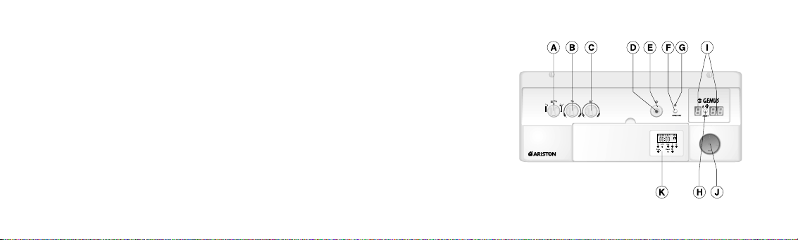
CONTROL PANEL
A. Selector Knob for
Summer/Winter/Flue Test Modes
B. Domestic Hot Water Temperature
Adjustment Knob
C. Central Heating Temperature
Adjustment Knob
D. On/Off L.E.D.
E. On/Off Knob
F. "COMFORT"/Heating Only
Function Push-button
G. “COMFORT"/Heating Only
Function L.E.D.
H. Reset Button
I. Multi-function Display
J. Heating System Pressure Gauge
K. Time Clock
Page 9

276 -9-
HELPFUL SUGGESTIONS
To get the most out of your boiler, we have provided you with some useful advice on
proper use and maintenance:
- Periodically check the system pressure using the pressure
gauge “J” and make sure that the pressure is between 1.0 and
1.5 bar (the blue part on the gauge) when the system is off and
cool.If the pressure is below the minimum recommended value,
the pressure must be brought into the acceptable range.Consult
your installer for checking and refilling the system.
If the pressure level drops on a frequent basis, it is likely that there is a water leak
in the system. If this is the case, your installer must inspect the system.
2. OPERATING INSTRUCTIONS
CAUTION
Installation, start-up, adjustments and maintenance must be performed by
a competent person only in accordance with the current Gas Safety
(Installation & Use) Regulations and the instructions provided. Improper
installation may cause damage or injury to individuals, animals and
personal property,for which the manufacturer will not be held liable.
To ensure efficient and safe operation it is recommended that the boiler is
serviced annually by a competent person.
If it is known or suspected that a fault exists on the appliance, it must not
be used until the fault has been corrected by a competent person.
J
Page 10

276 -10-
- The outer panels of the boiler's case must only be cleaned with a damp cloth,
do not use abrasive cleaners. The Control panel can be wiped with either a
damp or dry cloth. Spray polishes must not be used on the control panel
surface or knobs. Care must be taken in preventing any liquid entering the
appliance.
- If the water is exceptionally hard, install a water softener so that the efficiency
of the boiler remains the same over time, as this will consume less gas.
- To improve comfort levels and take full advantage of the heat produced by the
boiler, it is recommended that an external thermostat be installed.
A programmable timer for the thermostat is also recommended to schedule
when the boiler will turn on and off during the course of the day (or week), and
an outdoor sensor to optimise operating times.
- When the boiler is not in use for prolonged periods shut it down by pushing
button “E”, the red light “D” will go out; close the gas and water isolation
valves.
I
MPORTANT!
This will disable the anti-frost device - if the period of disuse is very cold it will
also be necessary to drain the heating system of water.
If you wish to leave the anti-frost device active, it is necessary to leave the
boiler on: this will not safeguard from possible "blocks" which may impair this
function.
- It is good practice to clean and service the appliance and central heating
system every year.
Call an Authorised Service Centre.
Page 11

276 -11-
code.
To reset the ignition system, the reset button “H”
must be pressed. Should the system fail to light a
second time, check to make sure that the gas cock
is open. If the problem persists, contact one of our
Authorised Service Centres.
Before starting the boiler, check the following:
- The water pressure on the pressure gauge “J”;
- That the gas cock and the inlet for domestic water are
open.
These models are equipped with electronic ignition which
utilises contact ionisation.
T o mak e the boiler oper ational, simply press theswitch “E”.
The red L.E.D.“D” will then tur n on. At this point the boiler
is ready for use: a centralised electronic control unit will automatically light the
main burner when needed without any intervention from the outside.If the burner
does not light within the pre-set safety time limit, the display will show an error
START-UP PROCEDURE
E
J
H
Page 12

Installation without an external thermostat:
- Turn on the power supply to the boiler by pressing the
switch “E”; the red L.E.D.“D” will then turn on;
- Turn the “A” selector knob to < >;
- Regulate the temperature of the heating system water in
the boiler by turning the “C” knob.The temperature can
vary between 42°C and about 82°C;
276
-12-
WINTER AND SUMMER OPERATING MODES
The boiler is fitted with a selector knob “A” which allows
you to switch between winter < > and summer < >
operating modes and vice versa
When the knob is set to < >, the boiler can serve the
dual purpose of providing heat or hot water for domestic
use. The supply of domestic hot water always takes
precedence over central heating.
When the knob is set to < >, the boiler cuts out the heating
system and only provides domestic hot water (when needed).
TURNING ON THE HEATING
A
E
D
Page 13

276 -13-
Installation with an external thermostat:
- Turn the “A” selector knob to < >;
- Turn on the power supply to the boiler by pressing the switch
“E”; the red L.E.D.“D” will then illuminate;
- Turn the thermostat knob “C” to the highest temperature
setting.
- In this instant the boiler is controlled by a time clock and
outdoor sensor; COMO (programmable thermostat) with or without an outdoor
sensor; CCM with or without outdoor sensor i.e depending on internal or
external temperature. At that point, the main burner will turn off and the
circulation pump will stop (if a pump overrun period has not been set, see
section 3.6.6. of the “I
NSTALLATION INSTRUCTIONS”).
- The temperature of the heating system water in the boiler
can be regulated on the alpha-numerical display. With this
type of installation, the heating thermostat acts on ambient
temperature directly.
H
A
C
C
Page 14

276
-14-
TURNING OFF THE HEATING
ENERGY SAVING SUGGESTIONS
To improve comfort and take full advantage of the heat produced by the boiler, it
is recommended that an external thermostat (remote control) be installed.
There are two control systems available:
- Timer and room temperature control only.
- Timer , room temperature and outdoor temperature sensor control.
Installation without an external thermostat:
To turn off the heating, turn the “A” selector knob to < >.The
boiler will still provide domestic hot water.
Installation with an external thermostat:
To turn off the heating, turn the “A” selector knob to < >.The
boiler will still provide hot water for domestic use. With an
external thermostat, there are a number of ways to turn off the
heating. For additional information, please consult the relative
manual.
A
A
Page 15

276 -15-
It is recommended that the temperature knob for the
domestic hot water is not set to a high temperature and
then mixed with cold water. Setting the thermostat to
medium temperature is preferable (see figure).
PRODUCTION OF DOMESTIC HOT WATER
Turn on the power to the boiler by pressing the switch “E”;
the red L.E.D.will then illuminate.
- With these settings, the boiler is already ready for use,
regardless of the position of the “A” selector knob.
- Turn the “B” knob to select the temperature for the hot
water (between 44°C and about 56°C depending on the
flow rate of the water).
ADJUSTING THE TEMPERATURE OF THE DOMESTIC HOT WATER
B B
Page 16

276
-16-
COMFORT FUNCTION 24 MFFI
HEATING ONLY BUTTON 24 RFFI SYSTEM
The supply of water for domestic use can become more
convenient by means of the “COMFORT” function, which
maintains the secondary exchanger at a preset temperature
when the boiler is not running; thereby allowing a quicker
delivery of domestic water when required. This function is
activated by pressing the “F” button on the control panel.
When the function is on, a green L.E.D.on the control panel will
illuminate.
N
OTE:If the “COMFORT” function is on during the pump overrun period, it will be temporarily
deactivated. The green L.E.D. will remain on to indicate that the boiler will resume the
“COMFORT” mode once the pump overrun period is complete.
This function can be activated by pressing the “F” button on
the control panel.When the function is on, a green L.E.D.on
the control panel will illuminate.This means that the external
cylinder is not kept at the set temperature and that only the
anti-frost protection is on.When the temperature falls below
5°C, the boiler ignites and heats the water until the
temperature exceeds 10°C.
F
F
Page 17

276 -17-
- Diagnostics Stage (precedes all other functions)
0 No Request for Heat
C Heating, Burner Off
C. Heating, Burner On
c Pump Overrun for Heating
d Water for Domestic Use, Burner Off
d. Water for Domestic Use, Burner On
h Pump Overrun for Water for Domestic Use
b Storage Cylinder, Burner Off (SYSTEM version)
b. Storage Cylinder, Burner On (SYSTEM version)
NOTE: the flashing dot on the left-hand display always indicates “burner off”;
the still dot indicates “bur ner on”.
The right-hand display (two-digit) shows:
- in heating mode: temperature of heating system flow;
- in domestic hot water mode: temperature domestic hot water.
SHUTDOWN PROCEDURE
To turn off the main burner, simply press the switch “E”;
the red L.E.D.“D” will then turn off. As a precautionary
measure, it is recommended that the gas cock located
on the bottom of the boiler, is also turned off.
When the system is operating, i.e. while the boiler is fulfiling its normal functions,the
left-hand display will show a series of letters indicating the following functions:
DISPLAY:VIEWING NORMAL FUNCTIONS
LEFT RIGHT
Page 18

276
-18-
TIME CLOCK
The steps marked with the symbol are necessary to carr y out a switching
program.
PREPARING FOR OPERATION
Activate the “Reset” switch to reset the time switch to its default settings (activate
using a pencil or similar pointed instrument). Do this:
- every time you wish to “Reset” the time switch;
- to erase all switching times and the current time of day
After approximately two seconds the following display appears:
Weekdays blinks
Input time Enter minutes
Enter
switching time
Summer and
winter time
setting
Reset
Enter weekdays
Enter the hour
Manual switch
Page 19

276 -19-
ENTER CURRENT TIME AND WEEKDAY
Keep the “ ” key pressed down. During the summer
time period press the +/-1h key once.
Enter the hour using the “h” key.
Enter the minutes using the “m” key.
Enter the day using the “Day”key.
1 = Mon ....... 7 = Sun
Release the “ ” key .
The colon now blinks once a second.
AM/PM
TIME DISPLAY
If you press the “+/-h” and “h” keys at the same time, the time display switches
into the AM/PM mode.
NOTE
: If you keep the “h” and “m”keys pressed down for more than 2 seconds,
the display will enter fast forward scroll mode.
ENTERING THE SWITCHING TIMES
If your entry is incomplete, the segments not yet
selected will blink in the display.
You have 20 memory locations available.Each switching
time takes up one memory location.
Keep pressing the “Prog” key until a free memory
location is shown in the display “-- : --”.
Program ON or OFF with the “”key:
“”= ON - “”= OFF.
Page 20

276 -20-
Enter the hour using “h”; enter the minutes using “m”.
If a switching command is to be carried out every day (1 2 3 4 5 6 7) then store
using the “”key, otherwise select the days it is to be carried out on by using
the “Day” key.
When the day selection is left blank, the programmed switching instruction
operates at the same time every day.
1 2 3 4 5 6 7 Monday ..... Sunday
1 2 3 4 5 6 Monday ..... Saturday
1 2 3 4 5 Monday ..... Friday
1 2 3 4 5 6 7 Saturday ..... Sunday
1 Monday
..... (selection of single days)
7 Sunday
Store using the “”key or push “Prog” key if you are going to continue
programming.The time switch enters the automatic operating mode and displays
the current time of day. Begin any further entr y of a switching time with the
“Prog” switch.
If necessary, once you have finished programming and have returned to the
current time display, by pressing the “”button, the timer will not automatically
switch to the current programmed status until the next timed setting.You can put
the timer into the correct mode with the “”key.
Page 21

276 -21-
ADDITIONAL FUNCTIONS
Switching from summer time to winter and vice versa.
Press the “+/-1h” key once.
M
ANUAL OVERRIDE KEY
With the “”key you can change the current switching settings at any time.
The switching program already entered is not altered.
= ON
= OFF
= OFF
= ON
= ON
= OFF
AUTOMATIC
OPERATION
MANUAL
OPERATION
CONTINUOUS
OPERATION
[ ]
The switching times
correspond to the program
entered.
If the current switching mode
is changed manually, the
next switching time will be
carried out automatically
again according to the
entered switching program.
You can only return to
automatic mode from the
continuously ON and
continuously OFF switching
modes by pressing the
“”key.
Page 22

276 -22-
Pressing the “Prog” key displays the programmed
switching times until the first free memory location
appears in the display “-- : --”.
If you now press the “Prog” key once again, the
number of free memory locations will be displayed,
e.g. “Fr 20”. If all memory locations are occupied, the
display “Fr 00” appears.
C
HANGING THE PROGRAMMED SWITCHING TIMES
Press the “Prog” key repeatedly until the switching time you want to change is
displayed. You can now enter the new data. See “E
NTERING THE SWITCHING TIMES”.
NOTES ON STORING SWITCHING TIMES:
If you end your entry of the switching times by pressing the “Prog” key, the
switching time you have entered will be stored and the next memory location
displayed.
Entry of further switching times is also carried out as described in “E
NTERING THE
SWITCHING TIMES”.
In addition, a complete switching command is stored automatically after around
90 seconds provided no other key is pressed.
The time switch then enters the automatic operating mode and displays the
current time again.
Page 23

276 -23-
3. USEFUL INFORMATION
BOILER SHUTDOWN
The boiler is equipped with safety devices which intervene in certain situations
to shutdown the boiler.Some of these situations are signalled by the boiler and
can be corrected by the user.
SHUTDOWN DUE TO IGNITION FAILURE
This anomaly is indicated by “A01” on the display.
To reset the boiler, press and then release the “H”
button.
At this point, the electronic ignition system will
attempt to light the burner again.
Should the boiler fail to ignite a second time,
check that the external gas cock is open.If the
problem persists, contact an Authorised
Service Centre.
DELETING INDIVIDUAL SWITCHING TIMES
Press the “Prog” key repeatedly until the switching time you wish to delete is
shown in the display.
Then set to “--” using the “h” or “m” key and keep the “”key pressed down
for around 3 seconds.
The switching time is now erased and the current time is displayed.
H
Page 24

276
SHUTDOWN DUE TO OVERHEATING
This anomaly is indicated by “E03” on the
display. The boiler has shutdown because the
safety thermostat detected that the boiler
temperature has exceeded the maximum limit.
To reset this state, wait until the boiler has
cooled and press the button “H”.
If the safety thermostat operates on a frequent
basis, contact one of our Authorised Service
Centres.
This anomaly is indicated by “A21” on the display.
One of the possible causes of this shutdown situation
could be the lack of water in the boiler or water
circulation failure in the primary heating circuit.
Check the system pressure on the pressure gauge “J”
and, if it is less than 0.5 bar, try bringing the system
pressure up to a mean value of 1.0 bar by opening the
water inlet valve.Then reset by turning the boiler off and
then back on by pressing the button “H”.
-24-
SHUTDOWN DUE TO INSUFFICIENT
WATER CIRCULATION
J
H
Page 25

276 -25-
If this situation persists, contact one of our Authorised Service Centres.
OTHER SHUTDOWN SITUATIONS
Should a shutdown situation indicated on the display by the following letters and
figures occur, E04, E05, E08, E20, E21, E22, E23, E56, E64, E66, E74, E99 contact one of
our Authorised Service Centres.
If instead the display shows one of the shutdown situations indicated by the
following letters and figures, A02, A03, A07, A19, A20, A22, A99, try resetting the boiler
by pressing the reset button “H”.If the boiler shuts off again, contact one of our
Authorised Service Centres.
H
Page 26

276
FLUE TEST FEATURE
(ONLY FOR AUTHORISED PERSONNEL)
The “A” Summer/Winter/Flue Test selector knob can be
set to < > to bypass temperature adjustment on the
heating circuit for the purpose of analysing the fumes
produced by combustion. To access this mode, open a
water tap so that the flow rate is no less than 8 litres per
minute. Then push the “A” selector knob in and turn it
from < > or < > to the < > position.
-26-
CAUTION!
The flue test function makes the boiler run continuously at its maximum power.
This condition should be used exclusively by authorised personnel.
TEST MODE
The P.C.B.allows for the boiler to be pushed at its maximum or minimum thermal
capacity. For the relevant information, refer to section 3.7.5.of the “INSTALLATION
INSTRUCTIONS”.
N.B. Should the boiler not be used for a long period of time, the condensate
trap must be filled up again before re-starting the boiler. Failure to add
water to the trap is dangerous because exhaust fumes could be released
into the environment.
A
Page 27

276 -27-
Page 28

23 99 84 1378 000
RAFICA E STAMPA SERIART - FABRIANO (AN) ITALIA TEL.0039+732+23069
Manufacturer: Merloni TermoSanitari SpA - Italy
Commercial subsidiary: MTS (GB) LIMITED
MTS Building
Hughenden Avenue
High Wycombe
Bucks HP13 5FT
Telephone: (01494) 755600
Fax:(01494) 459775
Technical Service Hot Line: (01494) 539579
 Loading...