


,QVWDOODWLRQ DQG 6HUYLFLQJ LQVWUXFWLRQV
E-Combi 24/30/38
E-System24/30
CONDENSING WALL HUNG
COMBINATION BOILER
G.C.N : 47 - 116 - 62 (24 kW)
G.C.N : 47 - 116 - 63 (30 kW)
G.C.N : 47 - 116 - 64 (38 kW)
CONDENSING WALL HUNG
O.H. BOILER
G.C.N : 41 - 116 - 34 (24 kW)
G.C.N : 41 - 116 - 35 (30 kW)
Country of destination GB, IE
INDEX |
|
Overview .......................................................................................... |
3 |
General Information............................................................................................. |
3 |
Advice for the Installer......................................................................................... |
4 |
CE Labelling............................................................................................................. |
4 |
Data Plate Symbols............................................................................................... |
4 |
Safety Regulations ................................................................................................ |
5 |
Product description......................................................................... |
6 |
Control Panel........................................................................................................... |
6 |
Overall View............................................................................................................. |
7 |
Overall Dimension ................................................................................................ |
8 |
Minimum Clearances ........................................................................................... |
8 |
Technical Information.......................................................................................... |
9 |
Installation ..................................................................................... |
11 |
Reference Standards .......................................................................................... |
11 |
Flushing and water treatment........................................................................ |
12 |
System Controls ................................................................................................... |
12 |
Location .................................................................................................................. |
12 |
Condensate Discharge ...................................................................................... |
13 |
Installing the Boiler............................................................................................. |
14 |
Method of positioning the boiler on the wall........................................... |
14 |
Connecting the boiler to the system............................................................ |
14 |
Safety valve discharge and Condensate Outlet ....................................... |
15 |
Gas Connection.................................................................................................... |
15 |
Water Connection ............................................................................................... |
15 |
Instructions for Opening the Casing and Performing an |
|
Internal Inspection.......................................................................................... |
16 |
Water circuit diagram ........................................................................................ |
17 |
Connecting the Flue........................................................................................... |
18 |
Fitting the Coaxial Flue (Ø 60/100 Horizontal).......................................... |
19 |
Fitting the 5” Flue (Ø 80/125 Horizontal / Vertical).................................. |
20 |
Fitting the Coaxial Flue (Ø 60/100 Vertical)................................................ |
20 |
Fitting the Twin Pipe (Ø 80/80)....................................................................... |
21 |
Table of flue exhaust duct lenghts................................................................ |
23 |
Type of air suction/flue gas exgaust ducting............................................ |
23 |
Electrical Connections....................................................................................... |
24 |
Peripheral Unit Connection............................................................................. |
24 |
Room Thermostat Connection ....................................................................... |
25 |
Electrical Diagram ............................................................................................... |
26 |
Commissioning .............................................................................. |
28 |
Initial Preparation................................................................................................ |
28 |
Electricity Supply................................................................................................. |
28 |
Filling the Heating System ............................................................................... |
28 |
Filling of the DHW System (Combi only)..................................................... |
28 |
Gas Supply ............................................................................................................. |
28 |
Water Treatment .................................................................................................. |
28 |
First Igniton Operation...................................................................................... |
29 |
First Ignition .......................................................................................................... |
30 |
Adjust the C.H. Ignition delay ......................................................................... |
30 |
Regulating the maximum C.H. power & Soft Ignition............................ |
30 |
Test Function and Combustion Analysis..................................................... |
31 |
Maximum gas flow combustion analysis.................................................... |
31 |
Minimum gas flow combustion analysis .................................................... |
31 |
Gas setting............................................................................................................. |
31 |
Boiler Protection Devices.............................................................. |
32 |
Boiler Protection Devices ................................................................................. |
32 |
Safety shut-off ...................................................................................................... |
32 |
Shutdown............................................................................................................... |
32 |
Anti-Frost Device ................................................................................................. |
32 |
Table summarising error codes...................................................................... |
32 |
Maintenance .................................................................................. |
33 |
General Comments............................................................................................. |
33 |
Oprational Test ..................................................................................................... |
33 |
Draining procedures .......................................................................................... |
33 |
Cleaning the primary exchanger................................................................... |
33 |
Combustion analysis.......................................................................................... |
33 |
Maintenance guide........................................................................ |
34 |
General Access ..................................................................................................... |
34 |
Electrical Unit........................................................................................................ |
35 |
Control box access............................................................................................ |
35 |
Fuse ........................................................................................................................ |
35 |
Main P.C.B. ............................................................................................................ |
36 |
Display P.C.B......................................................................................................... |
36 |
Hydraulic Unit....................................................................................................... |
37 |
Right hand hydraulic block assembly........................................................ |
37 |
3 Way valve unit............................................................................................... |
38 |
Draining.............................................................................................................. |
38 |
Automatic air vent .......................................................................................... |
39 |
Primary water pressure sensor ................................................................... |
39 |
Pump.................................................................................................................... |
40 |
C.H. Filter ............................................................................................................ |
41 |
D.H.W. Flow Switch assembly...................................................................... |
41 |
Left hand Hydraulic block assembly .......................................................... |
42 |
Secondary Exchanger.................................................................................... |
42 |
Condensate Trap................................................................................................ |
43 |
Safety valve.......................................................................................................... |
43 |
By-pass assembly .............................................................................................. |
44 |
Temperature sensor.......................................................................................... |
44 |
Manual air vent .................................................................................................. |
45 |
Main heat exchanger ....................................................................................... |
45 |
Burner Unit ............................................................................................................ |
46 |
Spaeck generator .............................................................................................. |
47 |
Electrodes ............................................................................................................ |
47 |
Burner.................................................................................................................... |
48 |
Fan .......................................................................................................................... |
49 |
Gas valve............................................................................................................... |
50 |
Annual Maintenance.......................................................................................... |
51 |
Fault Finding ......................................................................................................... |
52 |
Benchmark Commissioning Checklist ......................................................... |
53 |
Benchmark Service Interval Record.............................................................. |
54 |
Spare Parts Short List ......................................................................................... |
55 |

overview
These instructions are suitable for E-COMBI and E-SYSTEM boilers :
Do not forget to complete the Benchmark Commisioning Checklist.
The Benchmark Scheme
Benchmark places responsibilities on both manufacturers and installers.
The purpose is to ensure that customers are provided with the correct equipment for their needs, that it is installed, commissioned and serviced in accordance with the manufacturer’s instructions by competent persons and that it meets the requirements of the appropriate Building Regulations.
The Benchmark Checklist can be used to demonstrate compliance with Building Regulations and should be provided to the customer for future reference.
Installers are required to carry out installation, commissioning and servicing work in accordance with the Benchmark Code of Practice which is available from the Heating and Hotwater Industry Council who manage and promote the Scheme.
Visit www.centralheating.co.uk for more information.
To the Installer
As part of the commissioning of this appliance it is vital that the Log Book is completed and given to the Householder. Please ensure that your customer is aware of the importance of keeping the Log Book safe as a record of the installation and the appliance service history.
Please ensure that your customer is aware of the correct operation of the system, boiler and controls.
ARISTON recommend the use of protective clothing, when installing and working on the appliance i.e. gloves.
CUSTOMER CARE
ARISTON, as a leading manufacturer of domestic and commercial water heating appliances is committed to providing high quality products and a high quality after sales service.
Advice on installation or servicing can also be obtained by contacting the ARISTON Technical and Customer Service Departments at High Wycombe.
TECHNICAL DEPARTMENT |
CUSTOMER SERVICE DEPARTMENT |
||
Tel: |
0870 241 8180 |
Tel: |
0870 600 9888 |
Fax: |
01494 459775 |
Fax: |
01494 459775 |
GUARANTEE
The manufacturer’s guarantee is for 2 years from the date of installation or 18 months from the date of production. The guarantee is invalidated if the appliance is not installed in accordance with the recommendations made herein or in a manner not approved by the manufacturer.
To assist us in providing you with an efficient after sales service, please register your boiler at www.ariston.co.uk/register without delay.
CAUTION
In the United Kingdom, installation, start-up, adjustments and maintenance, must be performed by a competent person only, in accordance with the current Gas Safety (Installation & Use) Regulations and the instructions provided.
In the Republic of Ireland, the installation and initial start up of the appliance must be carried out by a Competent Person in accordance with the current edition of I.S.813 “Domestic Gas Installations”, the current Building Regulations, reference should also be made to the current ETCI rules for electrical installation.
All Gas Safe registered installers carry an ID card, and have a registration number. Both should be recorded in your boiler Log Book. You can check your installer is Gas Safe registered by visiting www.gassaferegister.co.uk or calling direct on 0800 408 5500.
Improper installation may cause damage or injury to individuals, animals and personal property for which the manufacturer will not be held liable.
To ensure efficient and safe operation it is recommended that the boiler is serviced annually by a competent person.
If it is known that a fault exists on the appliance, it must not be used until the fault has been corrected by a competent person.
This instruction booklet is especially designed for appliances installed in the UK and the Republic of Ireland
3

overview
Advice for the installer
The installation and first ignition of the boiler must be performedbyqualifiedpersonnelincompliancewithcurrent national regulations regarding installation, and in conformity with any requirements established by local authorities and public
health organisations.
After the boiler has been installed, the installer must ensure that the end user receives the declaration of conformity and the operating manual, and should provide all necessary information as to how the boiler and the safety devices should be handled.
This appliance is designed to produce central heating hot water for domestic use only.
It should be connected to a heating system and a distribution network for domestic hot water, both of which must be compatible with its performance and power levels.
The use of the appliance for purposes other than those specified is strictly forbidden. The manufacturer cannot be held responsible for any damage caused by improper, incorrect and unreasonable use of the appliance or by the failure to comply with the instructions given in this manual.
Installation, maintenance and all other interventions must be carried out in full conformity with the governing legal regulations and the instructions provided by the manufacturer. Incorrect installation can harm persons, animals and possessions; the manufacturing company shall not be held responsible for any damage caused as a result. The boiler is delivered in a carton. Once you have removed all the packaging, make sure the appliance is intact and that no parts are missing. If this is not the case, please contact your supplier.
Keep all packaging material (clips, plastic bags, polystyrene foam, etc.) out of reach of children as it may present a potential hazard.
In the event of a fault and/or malfunction, turn the appliance off, turn off the gas cock and do not attempt to repair it yourself. Contact a qualified professional instead.
Before any maintenance or repair work is performed on the boiler, make sure you have disconnected it from the electricity supply by switching the external bipolar switch to the “OFF” position and removing the fuse.
All repairs, which should only be performed using original spare parts, should be carried out by a qualified professional. Failure to comply with the above instructions could compromise the safety of the appliance and invalidate all liability on the part of the manufacturer.
In the event of any maintenance or other structural work in the immediate vicinity of the flue or flue gas exhaust devices and their accessories, switch the appliance off by switching the external bipolar switch to the “OFF” position and shutting off the gas control valve. When the work has been completed, a qualified technician must check the efficiency of the flue and the devices.
Turn the boiler off and turn the external switch “OFF” to clean the exterior parts of the appliance.
Clean using a cloth dampened with soapy water. Do not use aggressive detergents, insecticides or toxic products. If the appliance is used in full compliance with current legislation, it will operate in a safe, environmentally-friendly and cost-efficient manner.
If using kits or optional extras, make sure they are authentic.
CE labelling
The CE mark guarantees that the appliance conforms to the following directives:
-90/396/CEE
relating to gas appliances
-2004/108/CEE
relating to electromagnetic compatibility
-92/42/CEE
relating to energy efficiency
-2006/95/CEE
relating to electrical safety
Symbols used on the data plate
1 |
|
|
|
|
|
|
|
|
|
|
|
|
|
|
|
|
|
|
|
2 |
|
|
|
|
|
|
|
|
|
|
|
|
|
|
|
|
|
|
|
|
|
|
|
|
|
|
|
|
|
||
|
|
|
|
|
|
|
|
|
|
|
|
|
|
|
|
|
|
|
|
|
|
|
|
|
|
|
|
3 |
|
|
|
|
|
|
4 |
|
5 |
|
|
|
|
|
|
||||||||
|
|
|
|
|
|
|
|
|
|
|
|
|
|
|
|
|
|
|
|||||||
|
|
|
|
|
|
|
|
|
|
|
|
|
|
|
|
|
|
|
|
|
|
|
|||
|
|
|
|
|
|
|
|
|
|
|
|
|
|
|
|
|
|
|
|
|
|
|
|
|
|
|
|
|
|
|
|
|
|
|
|
|
|
6 |
|
|
|
|
|
|
|
|
|
|
|
||
|
|
|
|
|
|
|
|
|
|
|
|
|
|
|
|
|
|
|
|
|
|
|
|
|
|
|
|
|
|
|
|
|
|
|
|
|
|
|
|
|
|
|
|
|
|
|
|
|
|
|
|
|
|
|
|
|
|
|
|
|
|
|
|
|
|
|
|
|
|
|
|
|
|
|
|
|
|
|
|
|
|
|
|
|
|
|
|
|
|
7 |
|
|
|
|
|
|
|
|
|
|
|
|
|
|
|
|
|
|
|
|
|
|
|
|
|
|
|
|
|
|
|
|
|
|
|
|
|
|
|
|
|
8 |
|
|
|
|
|
|
|
|
|
MAX |
|
|
MIN |
|
|
|
|
|
|||||
|
|
9 |
|
|
|
|
12 |
|
|
Q |
|
14 |
|
|
|
|
|
|
|||||||
|
|
|
|
|
|
|
|
13 |
|
|
P60/80°C |
|
|
15 |
|
|
|
|
|
|
|
||||
|
|
|
|
|
|
|
|
|
|
|
|
|
|
|
|
|
|
|
|
|
|
||||
|
|
|
|
|
|
|
|
|
|
|
|
|
|
|
|
|
|
|
|
|
|
|
|
|
|
|
|
|
|
|
|
|
|
|
|
|
16 |
|
17 |
18 |
|
|
|||||||||
10 |
|
11 |
|
|
|
|
|
|
|
|
|
|
|
||||||||||||
|
|
|
|
|
|
|
|
|
|
|
|
|
|
|
|
|
|
|
|
|
|
|
|
|
|
|
|
|
|
|
|
|
|
|
|
|
|
|
|
|
|
|
|
|
|
|
|
|
|
||
|
|
|
|
|
|
|
|
|
|
|
|
|
|
|
|
|
|
|
|
|
20 |
|
|
||
|
|
|
|
|
|
|
|
|
|
|
|
|
|
|
|
|
|
|
|
|
|
||||
|
|
|
|
|
|
|
|
19 |
|
|
|
|
|
|
|
|
|
21 |
|
|
|||||
|
|
|
|
|
|
|
|
|
|
|
|
|
|
|
|
|
|
|
|
|
22 |
|
|
||
|
|
|
|
|
|
|
|
|
|
|
|
|
|
|
|
|
|
|
|
|
|
|
|||
|
|
|
|
|
|
|
|
|
|
|
|
|
|
|
|
|
|
|
|
|
|
|
|
|
|
|
|
|
|
|
|
|
|
|
|
|
|
|
|
|
|
|
|
|
|
|
|
|
|
|
|
Legend :
1.Brand
2.Manufacturer
3.Boiler model - Serial number
4.Commercial reference
5.Certification number
6.Destination country - gas category
7.Gas setting
8.Installation type
9.Electrical data
10.Maximum domestic hot water pressure
11.Maximum heating pressure
12.Boiler type
13.NOx class / Efficiency
14.Input rating nominal heating
15.Power ouput heating
16.DHW specific flow rate
17.Boiler output efficiency
18.Input rating nominal DHW
19.Gases which may be used
20.Minimum ambient temperature for use
21.Max. central heating temperature
22.Max. domestic hot water temperature
4
overview
Safety regulations
Key to symbols:
Failure to comply with this warning implies the risk of personal injury, in some circumstances even fatal.
Failure to comply with this warning implies the risk of damage, in some circumstances even serious, to property, plants or animals.
Install the appliance on a solid wall which is not subject to vibration.
Noisiness during operation.
When drilling holes in the wall for installation purposes, take care not to damage any electrical wiring or existing piping.
Electrocution caused by contact with live wires. Explosions, fires or asphyxiation caused by gas leaking from damaged piping. Damage to existing installations. Flooding caused by water leaking from damaged piping.
Perform all electrical connections using wires which have a suitable section.
Fire caused by overheating due to electrical current passing through undersized cables.
Protect all connection pipes and wires in order to prevent them from being damaged.
Electrocution caused by contact with live wires. Explosions, fires or asphyxiation caused by gas leaking from damaged piping. Flooding caused by water leaking from damaged piping.
Make sure the installation site and any systems to which the appliance must be connected comply with the applicable norms in force.
Electrocution caused by contact with live wires which have been installed incorrectly.
Damage to the appliance caused by improper operating conditions.
Use suitable manual tools and equipment (make sure in particular that the tool is not worn out and that its handle is fixed properly); use them correctly and make sure they do not fall from a height. Replace them once you have finished using them.
Personal injury from falling splinters or fragments, inhalation of dust, shocks, cuts, pricks and abrasions.
Damage to the appliance or surrounding objects caused by falling splinters, knocks and incisions.
Use electrical equipment suitable for its intended use (in particular, make sure that the power supply cable and plug are intact and that the parts featuring rotary or reciprocating motions are fastened correctly); use this equipment correctly; do not obstruct passageways with the power supply cable, make sure no equipment could fall from a height. Disconnect it and replace it safely after use.
Personal injury caused by falling splinters or fragments, inhalation of dust, knocks, cuts, puncture wounds, abrasions, noise and vibration.
Damage to the appliance or surrounding objects caused by falling splinters, knocks and incisions.
Make sure any portable ladders are positioned securely, that they are suitably strong and that the steps are intact and not slippery and do not wobble when someone climbs them. Ensure someone provides supervision at all times.
Personal injury caused by falling from a height or cuts (stepladders shutting accidentally).
Make sure any rolling ladders are positioned securely, that they are suitably strong, that the steps are intact and not slippery and that the ladders are fitted with handrails on either side of the ladder and parapets on the landing.
Personal injury caused by falling from a height.
During all work carried out at a certain height (generally with a difference in height of more than two metres), make sure that parapets are used to surround the work area or that individual harnesses are used to prevent falls. The space where any accidental fall may occur should be free from dangerous obstacles, and any impact upon falling should be cushioned by semi-rigid or deformable surfaces.
Personal injury caused by falling from a height.
Make sure the workplace has suitable hygiene and sanitary conditions in terms of lighting, ventilation and solidity of the structures.
Personal injury caused by knocks, stumbling etc.
Protect the appliance and all areas in the vicinity of the work place using suitable material.
Damage to the appliance or surrounding objects caused by falling splinters, knocks and incisions.
Handle the appliance with suitable protection and with care.
Damage to the appliance or surrounding objects from shocks, knocks, incisions and squashing.
During all work procedures, wear individual protective clothing and equipment.
Personal injury caused by electrocution, falling splinters or fragments, inhalation of dust, shocks, cuts, puncture wounds, abrasions, noise and vibration.
Place all debris and equipment in such a way as to make movement easy and safe, avoiding the formation of any piles which could yield or collapse.
Damage to the appliance or surrounding objects from shocks, knocks, incisions and squashing.
All operations inside the appliance must be performed with the necessary caution in order to avoid abrupt contact with sharp parts.
Personal injury caused by cuts, puncture wounds and abrasions.
Reset all the safety and control functions affected by any work performed on the appliance and make sure they operate correctly before restarting the appliance.
Explosions, fires or asphyxiation caused by gas leaks or an incorrect flue gas exhaust.
Damage or shutdown of the appliance caused by out-of-control operation.
Before handling, empty all components that may contain hot water, carrying out any bleeding if necessary.
Personal injury caused by burns.
Descale the components, in accordance with the instructions provided on the safety data sheet of the product used, airing the room, wearing protective clothing, avoid mixing different products, and protect the appliance and surrounding objects.
Personal injury caused by acidic substances coming into contact with skin or eyes; inhaling or swallowing harmful chemical agents.
Damage to the appliance or surrounding objects due to corrosion caused by acidic substances.
If you detect a smell of burning or smoke, keep clear of the appliance, disconnect it from the electricity supply, open all windows and contact the technician.
Personal injury caused by burns, smoke inhalation, asphyxiation
5
product description
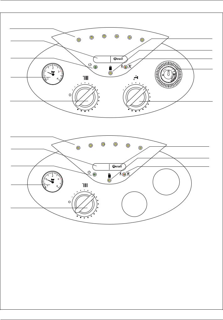
Control panel
E-COMBI
1
|
50° |
60° |
70° |
80° |
|
|
|
|
|
2 |
40° |
|
|
90° |
|
|
|
|
|
|
|
|
|
|
|
|
|
|
|
3 |
|
on/off |
|
|
|
|
|
|
|
|
|
|
|
|
|
|
|
|
|
|
|
|
|
|
|
|
|
|
|
|
|
|
|
|
|
|
|
|
|
|
|
|
|
|
|
|
|
|
|
|
|
|
|
|
|
|
|
|
|
4 |
|
|
|
|
|
|
|
I |
|
|
|
|
|
|
|
|
|
|
|
|
|
|
|
|
|
|
|
|
|
|
|
|
|
|
|
|
|
|
|
|
|
|
|
|
|
|
O |
|
|
|
|
|
|
|
|
|
|
||
|
|
|
|
|
|
|
|
||
|
|
|
|
|
|
|
|
|
|
|
|
|
|
|
|
|
|
|
|
5
E-SYSTEM
1
|
50° |
60° |
70° |
80° |
2 |
40° |
|
|
90° |
|
|
|
|
3
on/off
4
5
Legend :
1.Green indicator : CH temperature and error indicator
2.ON/OFF button
3.Green indicator : ON/OFF
4.Pressure gauge
5.Winter / Summer switch - Heating temperature regulation knob
6.Domestic Hot Water adjustment knob (E-Combi models)
7.Time clock (E-Combi models)
8.Green indicator : flame ON Red indicator : lockout light
9.Yellow indicator : flashing error light
10.RESET button
10
9
8
7
6
10
9
8
6

product description
Overall view
E-COMBI |
|
|
1 |
22 |
|
|
||
2 |
|
|
|
21 |
|
3 |
|
|
|
20 |
|
4 |
19 |
|
|
18 |
|
5 |
|
|
6 |
17 |
|
7 |
|
|
|
16 |
|
|
15 |
|
8 |
|
|
|
14 |
|
9 |
13 |
|
10 |
||
12 |
||
|
||
11 |
|
E-SYSTEM |
|
1 |
22 |
|
|
2 |
|
|
21 |
3 |
|
|
20 |
4 |
19 |
|
18 |
5 |
|
6 |
17 |
7 |
|
|
16 |
|
14 |
9 |
|
10 |
12 |
|
|
11 |
|
1. |
Flue connector |
13. |
D.H.W. Flow switch |
2. |
Manual air vent |
14. |
Circulation pump with auto air vent |
3. |
Burner |
15. |
Diverter valve |
4. |
Detection electrode |
16. |
Low water pressure switch |
5. |
C.H. Return temperature probe |
17. |
Silencer (according to model) |
6. |
C.H. Flow temperature probe |
18. |
Modulating fan |
7. |
Gas valve |
19. |
Ignition electrodes |
8. |
Secondary heat exchanger |
20. |
Ignitor |
9. |
Trap |
21. |
Thermal fuse |
10. |
C.H. pressure relief valve |
22. |
Combustion analysis test point |
11.Electrical box
12.C.H. circuit filter
7
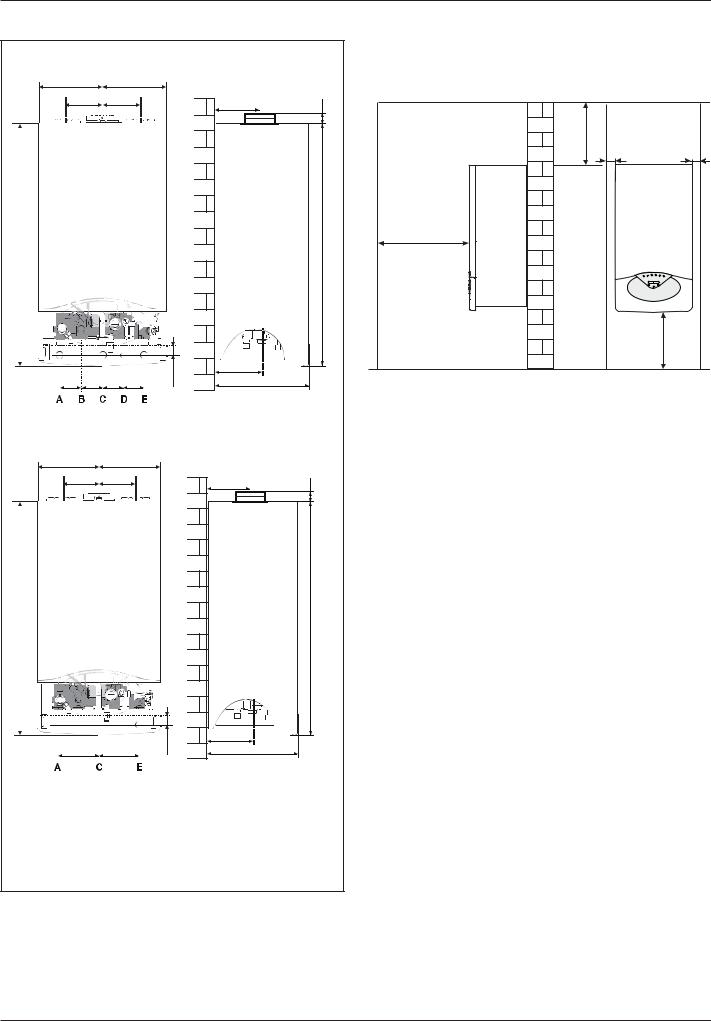
product description
Overall Dimensions |
Minimum clearances |
|
|
|
|
|
|
|
In order to allow easy access to the boiler for maintenance operations, |
|
E-COMBI |
|
|
|
|
|
|
the boiler must be installed in accordance with the clearances stated |
|
|
|
|
|
|
|
to the left (opposite). |
|
|
|
|
|
|
|
|
|
|
|
200 |
|
|
200 |
|
|
|
|
|
120 |
120 |
|
180 |
25 |
|
|
||
|
|
|
|
|
|
|
|
|
|
|
|
|
|
|
|
300 |
5 |
|
|
|
|
|
|
|
5 |
|
770 |
|
|
|
|
|
770 |
450 |
|
|
|
|
|
|
|
|
|
|
|
|
|
|
|
|
|
|
300 |
|
|
|
|
28 |
150 |
|
|
|
65 |
67 |
67 |
65 |
315 |
mod. 24 |
|
|
|
|
|
|
||||||
|
|
|
|
|
385 |
mod. 30/35 |
|
|
E-SYSTEM |
|
|
|
|
|
|
|
|
200 |
|
200 |
|
|
|
|
|
|
120 |
120 |
|
|
180 |
25 |
|
|
|
|
|
|
|
|
|
|
|
|
770 |
|
|
|
|
|
770 |
|
|
|
|
|
|
28 |
150 |
|
|
|
132 |
|
132 |
|
315 |
mod. 24 |
|
|
|
|
|
|
|
|
||||
|
|
|
|
|
385 |
mod. 30 |
|
|
A. Central Heating Flow |
|
|
|
|
|
|||
B. Domestic Hot Water Outlet |
|
|
|
|
|
|||
C. Gas Inlet |
|
|
|
|
|
|
|
|
D. Domestic Cold Water Inlet |
|
|
|
|
|
|||
E. Central Heating Return |
|
|
|
|
|
|||
8 |
|
|
|
|
|
|
|
|

product description
Technical Data
GENERAL NOTE
POWER SPECIFICATIONS
EMISSIONS
ELECTRICAL D. H. W. CIRCUIT HEATING CIRCUIT
Model E-COMBI |
|
|
|
24 |
30 |
38 |
|
|
|
|
|
|
|
CE Certification (pin) |
|
|
|
|
0085BR0347 |
|
|
|
|
|
|
||
Boiler type |
|
|
|
B23-B33-C13-C33-C43-C53-C83 |
||
Max/min nominal calorific flow rate (Pci) |
Qn |
|
kW |
22.0/5.5 |
|
|
|
28.0/6.5 |
31.0/7.5 |
||||
|
|
|
|
|
|
|
Max/min nominal calorific flow rate (Pcs) |
Qn |
|
kW |
24.4/6.1 |
31.1/7.2 |
34.4/8.3 |
|
|
|
|
|
|
|
Domestic hot water max/min nominal calorific flow rate (Pci) |
Qn |
kW |
25.0/5.5 |
30.0/6.5 |
38.0/7.5 |
|
|
|
|
|
|
|
|
Domestic hot water max/min nominal calorific flow rate (Pcs) |
Qn |
kW |
27.8/6.1 |
33.3/7.2 |
42.2/8.3 |
|
|
|
|
|
|
|
|
Max/min power output (80°C-60°C) |
Pn |
|
kW |
21.6/5.2 |
27.4/6.2 |
30.3/7.3 |
|
|
|
|
|
|
|
Max/min power output (50°C-30°C) |
Pn |
|
kW |
23.5/5.8 |
29.5/6.9 |
33.1/8.0 |
|
|
|
|
|
|
|
Domestic hot water max/min power output |
Pn |
|
kW |
25.0/5.0 |
30.0/6.0 |
38.9/7.1 |
|
|
|
|
|
|
|
Combustion efficiency (of flue gas) |
|
|
% |
97.9 |
97.9 |
98.0 |
|
|
|
|
|
|
|
Nominal calorific flow rate efficiency (60/80°C) Hi/Hs |
|
|
% |
98.0/88.2 |
98.0/88.2 |
97.6/87.9 |
|
|
|
|
|
||
Nominal calorific flow rate efficiency (30/50°C) (condensation) Hi/Hs |
% |
107.0/96.4 |
105.3/94.8 |
106.9/96.3 |
||
|
|
|
|
|
|
|
Efficiency at 30% at 30°C (condensation) Hi/Hs |
|
|
% |
108.0/97.3 |
110.3/99.3 |
107.2/96.5 |
|
|
|
|
|
|
|
Efficiency at 30% at 47°C Hi/Hs |
|
|
% |
101.0/90.9 |
98.2/88.4 |
103.1/92.8 |
|
|
|
|
|
|
|
Minimum calorific flow rate efficiency (60/80°C) Hi/Hs |
|
|
% |
95.0/85.5 |
95.6/86.1 |
96.8/87.2 |
|
|
|
|
|
|
|
Efficiency rating (dir. 92/42/EEC) |
|
|
stars |
**** |
**** |
**** |
Sedbuk Band Rating |
|
|
band |
A / 90.3 |
A / 90.1 |
A / 90,1 |
|
|
|
|
|
|
|
Loss when stopped (ΔT = 50°C) |
|
|
% |
0.2 |
0.1 |
0.1 |
|
|
|
|
|
|
|
Loss of burner gas when operating |
|
|
% |
2.1 |
2.1 |
2.0 |
Available air pressure |
|
|
Pa |
137 |
141 |
132 |
|
|
|
|
|
|
|
NoX class |
|
|
class |
5 |
5 |
5 |
|
|
|
|
|
|
|
Flue gas temperature (G20) (80°C-60°C) |
|
|
°C |
63 |
63 |
63 |
|
|
|
|
|
|
|
CO2 content (G20) (80°C-60°C) |
|
|
% |
9.0 |
9.0 |
9.6 |
|
|
|
|
|
|
|
CO content (0%O2) (80°C-60°C) |
|
|
ppm |
< 100 |
< 100 |
< 125 |
|
|
|
|
|
|
|
O2 content (G20) (80°C-60°C) |
|
|
% |
4.5 |
4.5 |
3,5 |
|
|
|
|
|
|
|
Maximum flue gas flow (G20) (80°C-60°C) |
|
|
Kg/h |
41.2 |
49.4 |
59.2 |
|
|
|
|
|
|
|
Excess air (80°C-60°C) |
|
|
% |
27 |
27 |
20 |
Expansion vessel inflation pressure |
|
|
bar |
1 |
1 |
1 |
|
|
|
|
|
|
|
Maximum heating pressure |
|
|
bar |
3 |
3 |
3 |
|
|
|
|
|
|
|
Expansion vessel capacity |
|
|
L |
6.5 |
6.5 |
6.5 |
|
|
|
|
|
|
|
Maximum water capacity with in the appliance (75°C-35°C) |
|
L |
100/300 |
100/300 |
100/300 |
|
|
|
|
|
|
|
|
Min/max heating temperature (high temperature range) |
|
°C |
35/82 |
35/82 |
35/82 |
|
Domestic hot water max/min temperature |
|
|
°C |
36/60 |
36/60 |
36/60 |
|
|
|
|
|
|
|
Specific flow rate of domestic hot water (ΔT=30°C) |
|
|
l/mn |
12.0 |
15.0 |
18.2 |
|
|
|
|
|
|
|
Quantity of hot water ΔT=25°C |
|
|
l/mn |
14.4 |
18.0 |
21.8 |
|
|
|
|
|
|
|
Quantity of hot water ΔT=35°C |
|
|
l/mn |
10.3 |
12.9 |
15.6 |
|
|
|
|
|
|
|
Hot water comfort rating (EN13203) |
|
|
stars |
*** |
*** |
*** |
|
|
|
|
|
|
|
Hot water minimum flow rate |
|
|
l/mn |
< 2 |
< 2 |
< 2 |
|
|
|
|
|
|
|
Domestic hot water max/min pressure |
|
|
bar |
7/0.3 |
7/0.3 |
7/0.3 |
Power supply frequency/voltage |
|
|
V/Hz |
230/50 |
230/50 |
230/50 |
|
|
|
|
|
|
|
Total electrical power absorbed |
|
|
W |
114 |
115 |
150 |
|
|
|
|
|
|
|
Minimum ambient temperature for use |
|
|
°C |
+5 |
+5 |
+5 |
|
|
|
|
|
|
|
Protection level for the electrical appliance |
|
|
PI |
X5D |
X5D |
X5D |
|
|
|
|
|
|
|
Weight |
|
|
kg |
32 |
35 |
35,5 |
|
|
|
|
|
|
|
9

product description
GENERAL NOTE
POWER SPECIFICATIONS
EMISSIONS
ELECTRICAL D. H. W. CIRCUIT HEATING CIRCUIT
Model E-SYSTEM |
|
|
24 |
30 |
|
|
|
|
|
CE Certification (pin) |
|
|
0085BR0347 |
|
|
|
|
|
|
Boiler type |
|
|
B23-B33-C13-C33-C43-C53-C83 |
|
Max/min nominal calorific flow rate (Pci) |
Qn |
kW |
22.0/5.5 |
28.0/6.5 |
|
|
|
|
|
Max/min nominal calorific flow rate (Pcs) |
Qn |
kW |
24.4/6.1 |
31.1/7.2 |
|
|
|
|
|
|
|
|
|
|
|
|
|
|
|
Max/min power output (80°C-60°C) |
Pn |
kW |
21.6/5.2 |
27.4/6.2 |
|
|
|
|
|
Max/min power output (50°C-30°C) |
Pn |
kW |
23.5/5.8 |
29.5/6.9 |
|
|
|
|
|
|
|
|
|
|
Combustion efficiency (of flue gas) |
|
% |
97.9 |
97.9 |
|
|
|
|
|
Nominal calorific flow rate efficiency (60/80°C) Hi/Hs |
|
% |
98.0/88.2 |
98.0/88.2 |
|
|
|
|
|
Nominal calorific flow rate efficiency (30/50°C) (condensation) Hi/Hs |
% |
107.0/96.4 |
105.3/94.8 |
|
|
|
|
|
|
Efficiency at 30% at 30°C (condensation) Hi/Hs |
|
% |
108.0/97.3 |
110.3/99.3 |
|
|
|
|
|
Efficiency at 30% at 47°C Hi/Hs |
|
% |
101.0/90.9 |
98.2/88.4 |
|
|
|
|
|
Minimum calorific flow rate efficiency (60/80°C) Hi/Hs |
|
% |
95.0/85.5 |
95.6/86.1 |
|
|
|
|
|
Efficiency rating (dir. 92/42/EEC) |
|
stars |
**** |
**** |
Sedbuk Band Rating |
|
band |
A / 90.3 |
A / 90.1 |
|
|
|
|
|
Loss when stopped (ΔT = 50°C) |
|
% |
0.2 |
0.1 |
|
|
|
|
|
Loss of burner gas when operating |
|
% |
2.1 |
2.1 |
Available air pressure |
|
Pa |
137 |
141 |
|
|
|
|
|
NoX class |
|
class |
5 |
5 |
|
|
|
|
|
Flue gas temperature (G20) (80°C-60°C) |
|
°C |
63 |
63 |
|
|
|
|
|
CO2 content (G20) (80°C-60°C) |
|
% |
9.0 |
9.0 |
|
|
|
|
|
CO content (0%O2) (80°C-60°C) |
|
ppm |
< 100 |
< 100 |
|
|
|
|
|
O2 content (G20) (80°C-60°C) |
|
% |
4.5 |
4.5 |
|
|
|
|
|
Maximum flue gas flow (G20) (80°C-60°C) |
|
Kg/h |
41.2 |
49.4 |
|
|
|
|
|
Excess air (80°C-60°C) |
|
% |
27 |
27 |
Expansion vessel inflation pressure |
|
bar |
1 |
1 |
|
|
|
|
|
Maximum heating pressure |
|
bar |
3 |
3 |
|
|
|
|
|
Expansion vessel capacity |
|
L |
6.5 |
6.5 |
|
|
|
|
|
Maximum water capacity with in the appliance (75°C-35°C) |
L |
100/300 |
100/300 |
|
|
|
|
|
|
Min/max heating temperature (high temperature range) |
°C |
35/82 |
35/82 |
|
Domestic hot water max/min temperature |
|
°C |
36/60 |
36/60 |
Power supply frequency/voltage |
V/Hz |
230/50 |
230/50 |
Total electrical power absorbed |
W |
114 |
115 |
|
|
|
|
Minimum ambient temperature for use |
°C |
+5 |
+5 |
|
|
|
|
Protection level for the electrical appliance |
PI |
X5D |
X5D |
|
|
|
|
Weight |
kg |
32 |
35 |
10
installation
Reference Standards
In the United Kingdom, the installation and initial start-up of the boiler must be by a Gas Safe registered installer in accordance with the installation standards currently in effect, as well as with any and all local health and safety standards i.e. Gas Safe.
In the Republic of Ireland the installation and initial start-up of the appliance must be carried out by a Competent Person in accordance with the current edition of I.S.813“Domestic Gas Installations”and the current Building Regulations, reference should also be made to the current ETCI rules for electrical installation.
The installation of this appliance must be in accordance with the relevant requirements of the Local Building Regulations, the current I.E.E. Wiring Regulations, the by-laws of the local authority, in Scotland, in accordance with the Building Standards (Scotland) Regulation and Health and Safety document No. 635, “Electricity at Work Regulations 1989”and in the Republic of Ireland with the current edition of I.S. 813 and the Local Building Regulations (IE).
C.O.S.H.H.
Materials used in the manufacture of this appliance are non-hazardous and no special precautions are required when servicing.
Codes of Practice
Installation should also comply with the following British Standards Code of Practice:
BS 7593:1992 Treatment of water in domestic hot water central heating systems
BS 5546:1990 Installation of hot water supplies for domestic purposes
BS 5440-1:2008 |
Flues |
BS 5440-2:2009 |
Air supply |
BS 5449:1990 Forced ciculation hot water systems |
|
BS 6798:2009 Installation of gas fired hot water boilers of rated input not exceeding 70kW
BS 6891:1989 Installation of low pressure gas pipes up to 28mm BS 7671:2001 IEE Wiring Regulations
BS 4814:1990 Specification for expansion vessels BS 5482:1994 Installation of L.P.G.
Domestic heating compliance guide
and in the Republic of Ireland in accordancce with the following codes of practice:
I.S. 813 Domestic Gas Installations
Avoid installing the boiler where the air inlet can be polluted by chemical products such as chlorine (swimming pool area), or ammonia (hair dresser), or alkalin products (launderette).
Flue
Detailed information on flue assembly can be found in the “Connecting the Flue” section.
The boiler must be installed so that the flue terminal is exposed to the free passage of external air at all times and must not be installed in a place likely to cause nuisance. It must not be allowed to discharge into another room or space such as an outhouse or closed lean-to.
Condensing boilers have a tendency to form a plume of water vapour from the flue terminal due to the low temperature of the flue gasses. The terminal should therefore be located with due regard for the damage or discolouration that may occur to building within the vicinity and consideration must also be given to adjacent boundaries, openable windows the min acceptable clearances are shown opposite.
NOTE: THE FLUE MUST NOT BE INSTALLED IN A PLACE LIKELY TO CAUSE A NUISANCE AND POSITIONED TO ENSURE THAT PRODUCTS OF COMBUSTION DO NOT DISCHARGE ACROSS A BOUNDARY
It may be necessary to protect the terminal with a guard, if this is the case it will be necessary to purchase a stainless steel terminal guard. Reference should be made to the Building Regulations for guidance.
Ventilation
The room in which the boiler is installed does not require specific ventilation. If the boiler is installed in a cupboard or compartment ventilation is not required for cooling purposes.
Gas Supply
The gas installation and tightness testing must be in accordance with the requirements of BS6891. Ensure that the pipe size is adequate for demand including other gas appliances on the same supply.
Electrical Supply
The appliance requires an earthed 230V - 50 Hz supply and must be in accordance with current I.E.E. regulations.
It must also be possible to be able to completely isolate the appliance electrically.
Connection should be via a 3 amp double pole fused isolating switch with contact separation of at least 3mm on both poles.
Alternatively, a fused 3 amp, 3 pin plug and unswitched socket may be used, provided it is not used in a room containing a bath or shower, it. It should only supply the appliance.
Water Supply
The boiler is suitable for sealed systems only. The maximum working pressure for the appliance is 6 bar. All fittings and pipework for the appliance should be of the same standard. If there is a possibility of the incoming mains pressure exceeding 6 bar, particularly at night, then a suitable pressure limiting valve must be fitted.
The boiler is designed to provide hot water on demand to multiple outlets within the property. If there is a requirement for greater demands, for example if the boiler has several bathrooms and cloakrooms, a vented or unvented hot water storage system may be used.
Showers
Any shower valves used with the appliance should be of a thermostatic or pressure balanced type.
Refer to the shower manufacturer for performance guidance and suitability.
11

installation
Flushing and Water Treatment
The boiler is equipped with a stainless steel heat exchanger.
The detailed recommendations for water treatment are given in BS 7593:1992 (Treatment of water in domestic hot water central heating systems); the following notes are given for general guidance.
If the boiler is installed on an existing system, any unsuitable additives must be removed.
Under no circumstances should the boiler be fired before the system has been thoroughly flushed; the flushing procedure must be in line with BS 7593:1992.
We highly recommend the use of a flushing detergent appropriate for the metals used in the circuit. These include cleansers produced by Fernox BetzDearbon, whose function is to disolve any foreign matter that may be in the system.
In hard water areas or where large quantities of water are in the system the treatment of water to prevent premature scaling of the main exchanger is necessary.
The formation of scale heat compromises the efficiency of the thermic exchanger because small areas of scale cause a high increase of the temperature of the metallic walls and therefore add to the thermal stress of the heat exchanger.
Demineralised water is more aggressive so in this situation it is necessary to treat the water with an appropriate corrosion inhibitor. Any treatment of water by additives in the system for frost protection or for corrosion inhibition has to be absolutely suitable for all metals used in the circuit.
The use of a corrosion inhibitor in the sysem such as Fernox MB- 1, BetzDearborn Sentinel X100 or Fernox System Inhibitor is recommended to prevent corrosion (sludge) damaging the boiler and system.
If anti-freeze substances are to be used in the system, check carefully that they are compatible with the metals used in the circuit. ARISTON suggests the use of suitable anti-freeze products such as Fernox ALPHI 11, which will prevent rust and incrustation taking place. Periodicaly check the pH balance of the water/anti-freeze mixture of the boiler circuit and replace it when the amount measured is out of the range stipulated by the manufacturer (7 < pH < 8).
DO NOT MIX DIFFERENT TYPES OF ANTI-FREEZE
In under-floor systems, the use of plastic pipes without protection against penetration of oxygen through the walls can cause corrosion of the systems metal parts (metal piping, boiler etc), through the formation of oxides and bacterial agents.
To prevent this problem it is necessary to use pipes with an “oxygen proof barrier”, in accordance with standards DIN 4726/4729.
If pipes of this kind are not used, keep the system separate by installing heat exchangers of those with a specific system water treatment.
IMPORTANT
Failure carry out the water treatment procedure will invalidate the appliance guarantee.
System Controls
The boiler is electrically controlled and is suitable for most modern electronic time and temperature controls. The addition of such external controls can be beneficial to the efficient operation of the system. The boiler connections for external controls are 12V DC and so only controls of 12V DC that have voltage free contacts should be used. (page 25).
ARISTON supply a range of wired and wireless system controls. Contact your supplier for more details.
Location
The boiler can be installed on any suitable internal wall (suitable sound proofing may be required when installing onto a stud partition wall). Provision must be made to allow for the correct routing of the flue and siting of the terminal to allow the safe and efficient removal of the flue products.
A compartment or cupboard may be used provided that it has been built or modified for this purpose.
It is not necessary to provide permanent ventilation for cooling purposes. Detailed recommendations are given in BS 5440 Part 2.
If it is proposed that it is to be installed in a timber framed building then reference should be made to British Gas Document DM2, IGE/ UP/7 or advice sought from Gas Safe.
Where a room sealed appliance is installed in a room containing a bath or shower, the appliance and any electrical switch or appliance control, utilising mains electricity should be situated specifically in accordance with current IEE Wiring Regulations.
For unusual locations, special procedures may be necessary. BS 6798:2009 gives detailed guidance on this aspect.
12
installation
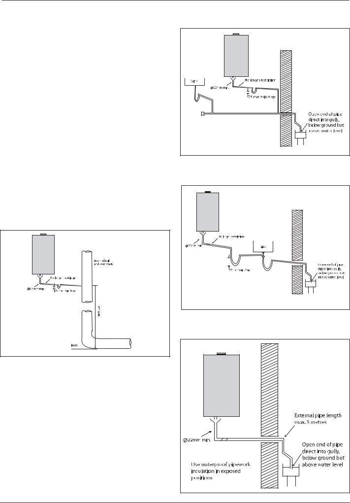
Condensate Discharge
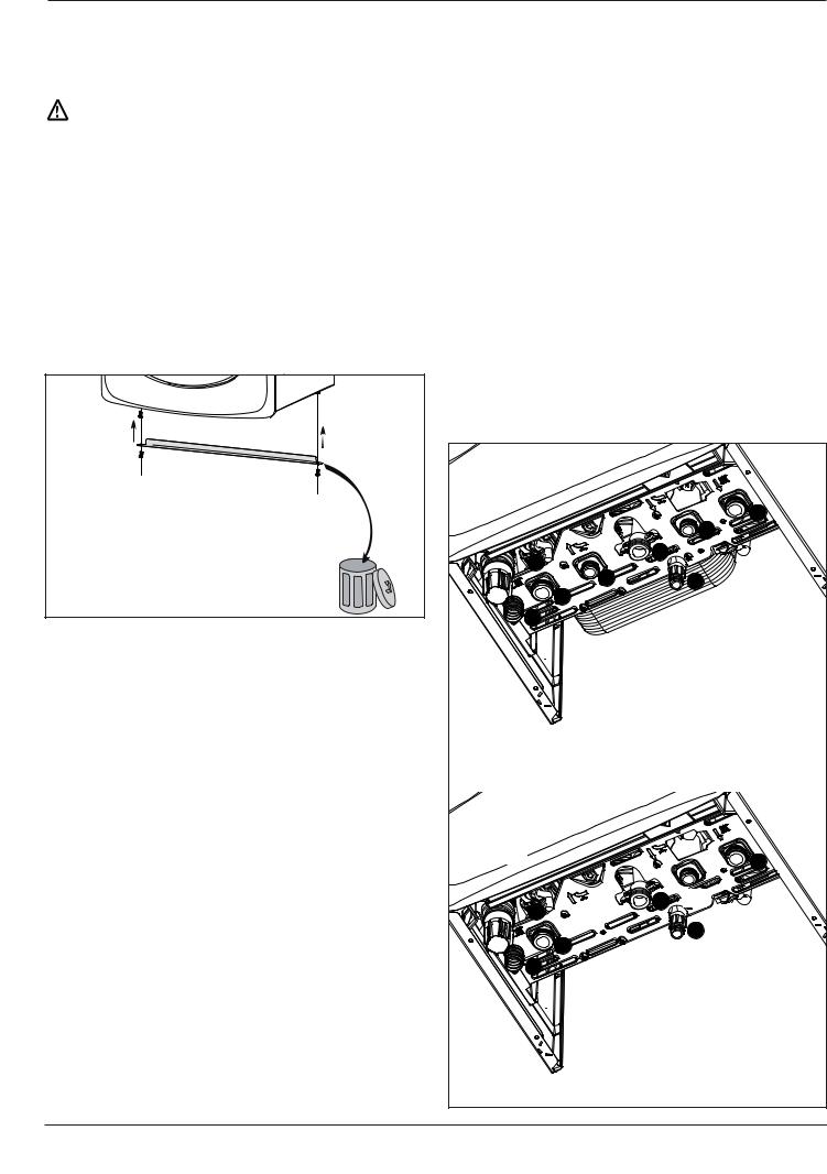
The condensate discharge hose from the boiler must have a continuous fall of 2.5o and must be inserted by at least 50mm into a suitable acid resistant pipe - e.g. plastic waste or overflow pipe. The condensate discharge pipe must have a minimum diameter of 22mm, must have a continuous fall and preferably be installed and terminated to prevent freezing.
The discharge pipe must be terminated in a suitable position:
i)Connecting into an internal soil stack (at least 450mm above the invert of the stack). A trap giving a water seal of at least 75mm must be incorporated into the pipe run, there also must be an air beak upstream of the trap.
ii)Connecting into the waste system of the building such as a washing maching or sink trap. The connection must be upstream of the washing machine/sink. If the connection is downstream of the waste trap then an additional trap giving a minimum water seal of 75mm and an air break must be incorporated in the pipe run, as above.
iii)Terminating into a gully, below the grid level but above the water level
iv)Into a soakaway
Note: If any condensate pipework is to be installed externally then it should be kept to a minimum and be insulated with a waterproof insulation and have a continuous fall. The total length of external pipe used should not exceed 3 metres.
Some examples of the type of condensate terminations can be found below.
1.Internal termination of condensate drainage pipe to internal stack.
2.External termination of condensate drainage pipe via internal discharge branch (e.g. sink waste) and condensate trap.
trap |
3.External termination of condensate drainage pipe via internal discharge branch (e.g. sink waste - proprietary fitting).
trap |
4.External termination of condensate drainage pipe via condensate trap
13 |
installation
Installing the Boiler
Please check that you are familiar with the installation requirement before commencing work (pages 7 - 13).
The installation accessories described in the following list are included in the boiler packaging:
-Hanging bracket
-A paper template (showing the dimensions of the boiler with 5 mm side clearances)
-Connection valves (compression)
-Washers
-Filling loop
-Installation, Servicing and Operating Instructions
-Flue gasket
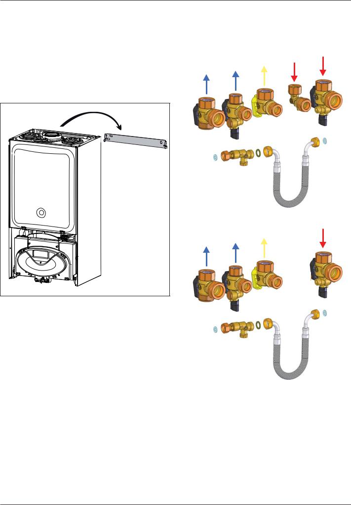
Connecting the boiler to the system
-Remove the boiler casing as described on page 16
-Remove the caps and connect the valves to the boiler using the washers provided
-4 x fibre washers for the CH flow and return, cold water inlet and hot water outlet connections
E-COMBI
Method of positioning the boiler on the wall
The paper template can be used to ensure the correct positioning of kitchen cabinets etc.
The paper template has to be fixed to the wall and used to locate the position of the hanging bracket and the centre for the flue hole.
Drill and plug the wall and secure the hanging bracket using the screws provided ensure the hanging bracket is level. Remove the boiler from its packaging and remove the front casing panel.
Place the boiler on the hanging bracket.
NOTE: THE APPLIANCE MUST NOT BE FITTED ON A COMBUSTIBLE WALL SURFACE.
Note: Connections viewed from behind boiler
E-SYSTEM
Note: Connections viewed from behind boiler
14
|
|
|
installation |
Safety Valve Discharge and Condense Outlet |
Gas connection |
|
|
The pressure relief valve pipe is made of copper. It should terminate |
Make sure, using the labels on the packaging and the data plate on |
||
below the boiler safely outside the premises. Care should be taken |
the appliance itself, that the boiler is in the correct country and that |
||
that it does not terminate over an entrance or window or where a |
the gas category for which the boiler was designed corresponds to |
||
discharge of heated water could endanger occupants or passers by. |
one of the categories available in the country where it will be used. |
||
Warning ! |
The gas supply piping must be created and measured out in |
||
compliance with specific legal requirements and in accordance with |
|||
Do not apply heat to the copper safety valve outlet pipe whilst it |
the maximum power of the boiler; you should also make sure that the |
||
is connected to the 3 bar safety relief valve. |
shut-off valve is the right size and that it is connected correctly. |
||
|
Check that the supplied gas corresponds to the type of gas for which |
||
Fill the central heating and DHW system and bleed air from the system |
the boiler was designed (see the data plate located on the appliance |
||
as described in the Commissioning instructions (page 30). |
itself). |
|
|
The system should be carefully checked for leaks, as frequent refilling |
It is also important to check that the pressure of the gas (methane |
||
could cause premature system corrosion or unnecessary scaling of |
or LPG) you will be using to feed the boiler is suitable, because if it |
||
the heat exchanger. The pipe from the trap should be connected to a |
is insufficient the power may be reduced, causing inconvenience for |
||
drain as described in the relevant regulations. |
the user. |
|
|
Pay special attention not to bend the condensate drain pipe in such |
|
|
|
a way as to interrupt the flow. Please only use drain pipe material |
Water connection |
|
|
compatible with condensate products (refer to BS 6798:2009). |
The illustration below shows the connections for the water and gas |
||
The condensate flow can reach 2 litres/hour because of the acidity of |
attachments of the boiler. See valves configuration on page 14. |
||
the condensate products (Ph close to 2), take care before operation. |
Check that the maximum water mains pressure does not exceed 6 bar; |
||
See page 13 for condensate discharge options. |
if it does, a pressure reducing valve must be installed. |
||
|
For the measuring of the pipes and of the heating bodies in the |
||
|
heating system, the residual head value should be calculated as a |
||
|
function of the requested flow rate, in accordance with the values |
||
|
shown in the circulation pump graph (page 16). |
||
A |
|
|
|
A |
E-COMBI |
|
|
|
|
|
( |
- remove the 2 screws A from the |
|
|
' |
transport bar |
& |
|
|
- dispose of the transport bar and |
|
||
) |
|
|
|
reassemble the fixing screws. |
% |
|
+ |
|
$ |
|
|
|
, |
|
|
|
A. Central heating Flow |
||
|
B. Domestic Hot Water Outlet |
||
|
C. Gas Inlet |
||
|
D. Domestic Cold Water Inlet |
||
|
E. Central Heating Return |
||
|
F. |
Safety Valve Discharge |
|
|
H. Drain Valve |
||
|
I. |
Drain condensate |
|
|
E-SYSTEM |
|
( |
|
|
|
|
|
& |
* |
|
|
) |
|
|
|
$ |
|
+ |
|
|
|
|
|
, |
|
|
|
* - Connection for Filling Loop |
||
|
|
|
15 |
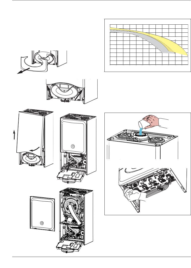
installation
Instructions for opening the casing and performing an internal inspection
Before performing any work on the boiler, first disconnect it from the electrical power supply using the external bipolar switch; removing the fuse and shutting off the gas cock.
To access the inside of the boiler, the following is necessary:
1.Remove the casing by unhooking it from the control panel (a)
2.Loosen the two screws on the front casing (b), pull it forwards and unhook it from the upper pins (c)
3.Lower the control panel (d)
4.Unhook the two clips on the combustion chamber panel and lift off (e).
(a)


(b) 
(c)
(d)
(e)
To calculate the size of the heating installation, refer to the "Available pressure" graph below.
Graph representing the available circulation pump pressure T20oC
mbar |
|
|
|
|
|
|
|
|
|
|
|
|
500 |
|
|
|
|
|
|
|
|
|
|
|
|
450 |
|
|
|
|
|
|
|
|
|
|
|
|
400 |
|
|
|
|
|
|
|
|
|
|
|
|
350 |
|
|
|
|
|
|
|
|
30-38 kW |
|
|
|
|
|
|
|
|
|
|
|
|
|
|
||
300 |
|
|
|
|
|
|
|
|
30-35 kW |
|
|
|
|
|
|
|
|
|
|
|
|
|
|
|
|
250 |
|
|
|
|
24 kW |
|
|
|
|
|
|
|
|
|
|
|
|
|
|
|
|
|
|
|
|
200 |
|
|
|
|
|
|
|
|
|
|
|
|
150 |
|
|
|
|
|
|
|
|
|
|
|
|
100 |
|
|
|
|
|
|
|
|
|
|
|
|
50 |
|
|
|
|
|
|
|
|
|
|
|
|
0 |
|
|
|
|
|
|
|
|
|
|
|
|
0 |
100 |
200 |
300 |
400 |
500 |
600 |
700 |
800 |
900 |
1000 |
1100 |
1200 |
|
|
|
|
|
|
|
|
|
|
|
|
l/h |
 Before the equipment is used, for the first time the trap must be filled with water. To do this, add approximately 1/4 litre of water via the flue outlet before fitting the flue system, or unscrew the cap on the trap positioned underneath the boiler, fill it with water and refit it.
 Warning!
Insufficient water in the trap can temporarily cause the flue gas to be expelled into the surrounding ambient air.
|
G |
|
E |
|
D |
F |
C |
|
|
B |
H |
A |
|
I |
|
16
installation
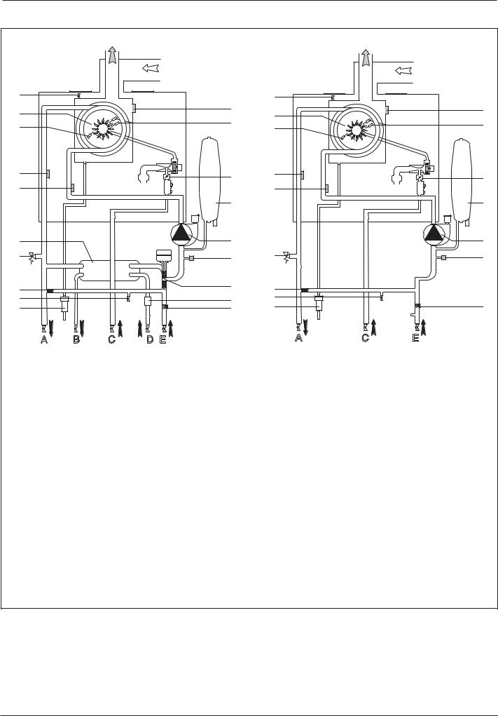
Water circuit diagram
E-COMBI |
|
|
|
E-SYSTEM |
|
|
|
|
|
|
|
|
|
||
1 |
|
|
|
|
1 |
|
|
|
|
|
|
|
|
|
|
2 |
|
|
|
19 |
2 |
|
19 |
|
|
|
|
|
|||
|
|
|
18 |
|
|
||
3 |
|
|
|
3 |
|
18 |
|
|
|
|
|
|
|||
4 |
|
|
|
17 |
4 |
|
17 |
|
|
|
|
|
|||
|
|
|
|
|
|
||
5 |
|
|
|
|
5 |
|
|
|
|
|
|
16 |
|
|
16 |
6 |
|
|
|
15 |
|
|
15 |
7 |
|
|
|
14 |
7 |
|
14 |
|
|
|
|
|
|
||
8 |
|
|
|
13 |
8 |
|
|
|
|
|
|
|
|
||
9 |
|
|
|
12 |
9 |
|
|
10 |
|
|
|
10 |
|
11 |
|
|
|
|
11 |
|
|||
|
$ |
% |
& |
' ( |
$ |
& |
( |
1. |
Manual air vent |
|
|
|
|
|
|
2. |
Burner |
|
|
|
|
|
|
3. |
Detection electrode |
|
|
|
|
|
|
4. |
C.H. flow temperature probe |
|
|
|
|
||
5. |
C.H. return temperature probe |
|
|
|
|
||
6. |
Secondary heat exchanger |
|
|
|
|
||
7. |
C.H. pressure relief valve |
|
|
|
|
||
8. |
By-pass |
|
|
|
|
|
|
9. |
Drain valve |
|
|
|
|
|
|
10. |
Condensate trap |
|
|
|
|
|
|
11. |
C.H. circuit filter |
|
|
|
|
|
|
12. |
D.H.W. Flow switch |
|
|
|
|
|
|
13. |
Diverter valve |
|
|
|
|
|
|
14. |
Low water pres switch |
|
|
|
|
||
15. |
Circulation pump |
|
|
|
|
|
|
16. |
Expansion vessel |
|
|
|
|
|
|
17. |
Modulating fan |
|
|
|
|
|
|
18. |
Ignition electrodes |
|
|
|
|
|
|
19. |
Thermal fuse |
|
|
|
|
|
|
|
|
|
|
|
|
|
17 |
 Loading...