

Ariston Combi A 24 MFFi, Combi A 30 MFFi Installation and Servicing Instructions

Combi A 24 MFFi
3
6
9
12
TEMP
MODE
MAN
AUTO
T
H
E
R
M
O
R
E
G
U
L
A
T
I
O
N
C
O
M
P
A
T
I
B
L
E
CCOOMMBBII AA
SSEERRIIEESS
Combi A 30 MFFi
Installation and
Servicing
Instructions
Type C Boilers
G.C.N: 47-116-44 (24 kW)
G.C.N: 47-116-45 (30 kW)
LEAVE THESE
INSTRUCTIONS WITH THE
END-USER
Country of destination
GB
IE

These instructions are suitable for the Combi A boilers :
Do not forget the Log Book!
MTS supports Benchmark, the heating industry code to ensure the correct installation, commissioning and servicing of
domestic central heating systems.
To The Householder
ake sure you have a completed Log Book for your boiler.
M
t contains important information about your particular installation that may be required by service engineers. The Log Book will
I
also provide contact details for the installer should you need guidance in the use of this appliance or if there are any problems.
As with your car, your boiler will work more reliably and efficiently if regularly serviced. We recommend an annual service
check. The service history of the appliance will be recorded on the Log Book.
In the unlikely event of any problems with your boiler or system you should first contact your installer. If your installer cannot
resolve the problem he should telephone our national service helpline.
A charge may be made if MTS Service is called out to resolve a non-product related fault.
Your statutory rights are not affected.
To The Installer
As part of the commissioning of this appliance it is vital that the Log Book is completed and given to the Householder. Please
ensure that your customer is aware of the importance of keeping the Log Book safe as a record of the installation and the
appliance service history.
Please ensure that your customer is aware of the correct operation of the system, boiler and controls.
his provides a record of the commissioning of your boiler.
T
MTS recommend the use of protective clothing, when installing and working on the appliance i.e. gloves.
CUSTOMER CARE
MTS, as a leading manufacturer of domestic and commercial water heating appliances is committed to providing high quality
products and a high quality after sales service.
Advice on installation or servicing can also be obtained by contacting the MTS Technical and Customer Service Departments
at High Wycombe.
TECHNICAL DEPARTMENT CUSTOMER SERVICE DEPARTMENT
Tel: 0870 241 8180 Tel: 0870 600 9888
Fax: 01494 459775 Fax: 01494 459775
GUARANTEE
The manufacturer’s guarantee is for 2 years from the date of purchase. The guarantee is invalidated if the appliance is not
installed in accordance with the recommendations made herein or in a manner not approved by the manufacturer. To assist us
in providing you with an efficient after sales service, please return the guarantee registration card enclosed with the boiler
without delay.
CAUTION
In the United Kingdom, installation, start-up, adjustments and maintenance, must be performed by a competent person only, in
accordance with the current Gas Safety (Installation & Use) Regulations and the instructions provided.
In the Republic of Ireland, the installation and initial start up of the appliance must be carried out by a Competent Person in
accordance with the current edition of I.S.813 “Domestic Gas Installations”, the current Buidling Regulations, reference should
also be made to the current ETCI rules for electrical installation.
All CORGI registered installers carry a CORGI ID card, and have a registration number. Both should be recorded in
your boiler Log Book. You can check your installer is CORGI registered by calling CORGI direct on:- (01256) 372300.
Improper installation may cause damage or injury to individuals, animals and personal property for which the manufacturer will
not be held liable. To ensure efficient and safe operation it is recommended that the boiler is serviced annually by a competent
person.
If it is known that a fault exists on the appliance, it must not be used until the fault has been corrected by a competent person.
This instruction booklet is especially designed for appliances installed in the UK and the Republic of Ireland
2

Contents
CUSTOMER CARE
Guarantee ............................................................................................................................................................2
Statutory Requirements .......................................................................................................................................2
Contents ...............................................................................................................................................................3
INTRODUCTION ..................................................................................................................................................4
USER INSTRUCTIONS........................................................................................................................................5
1 CONTROL PANEL...........................................................................................................................................5
2 HOW TO USE..................................................................................................................................................6
3 MAINTENANCE...............................................................................................................................................7
4 GUARANTEE...................................................................................................................................................7
5 PRACTICAL INFORMATION...........................................................................................................................7
6 SETTING THE TIME CLOCK ..........................................................................................................................8
6.1 SETTING THE MECHANICAL CLOCK ..................................................................................................8
6.2 SETTING THE DIGITAL CLOCK.............................................................................................................9
INSTALLERS’ INSTRUCTIONS.........................................................................................................................11
7 DESCRIPTION...............................................................................................................................................11
8 DIMENSIONS ................................................................................................................................................12
9 HYDRAULIC DATA .......................................................................................................................................12
10 INSTALLATION REQUIREMENTS................................................................................................................13
11 INSTALLING THE BOILER............................................................................................................................16
12 CONNECTING THE FLUE.............................................................................................................................18
12.1 FITTING THE COAXIAL FLUE (ø 60 / 100 Horizontal).........................................................................19
12.2 FITTING THE 5” FLUE (ø 80 / 125 Horizontal / Vertical).......................................................................19
12.3 FITTING VERTICAL FLUE (ø 60 / 100)
12.4 FITTING THE TWIN FLUE (ø 80 / 80)
13 ELECTRICAL CONNECTIONS .....................................................................................................................25
13.1 FITTING DIGITAL TIME CLOCK...........................................................................................................27
14 COMMISSIONING AND TESTING................................................................................................................
14.1 INITIAL PREPARATION........................................................................................................................28
14.2 INITIAL START-UP................................................................................................................................28
14.3 ADJUSTING THE CO2..........................................................................................................................29
14.4 GAS CONVERSION..............................................................................................................................29
14.5 ADJUSTING THE MAXIMUM HEATING POWER ................................................................................29
14.6 FITTING THE EXTERNAL SENSOR
14.7 EXTERNAL SENSOR SET-UP..............................................................................................................30
14.8 COMPLETION.......................................................................................................................................30
14.9 OPERATIONAL CHECKS
14.10 INSTRUCTING THE END USER...........................................................................................................31
15 FITTING THE CASING ..................................................................................................................................32
16 SEQUENCE OF OPERATION.......................................................................................................................
16.1 CENTRAL HEATING MODE .................................................................................................................33
16.2 DOMESTIC HOT WATER MODE..........................................................................................................34
17 ADJUSTMENTS AND SETTINGS.................................................................................................................35
.....................................................................................................................
.................................................................................................
...................................................................................................
.....................................................................................................29
Page
21
22
28
30
33
3

SERVICING INSTRUCTIONS
18 REPLACEMENT OF PARTS.........................................................................................................................42
18.1 To Gain General Access........................................................................................................................42
18.1.1 Removing the front panel.......................................................................................................................42
18.1.2 Lowering the control panel.....................................................................................................................42
18.2 Access to the Combustion Chamber .....................................................................................................43
18.2.1 Removing the combustion chamber front panel ....................................................................................43
18.2.2 Removing the burner .............................................................................................................................44
8.2.3Removing the detection electrode .........................................................................................................44
1
18.2.4 Removing the ignition electrode.............................................................................................................44
8.2.5Removing the fan...................................................................................................................................45
1
18.2.6 Removing the gas valve.........................................................................................................................45
18.2.7 Removing the heat exchanger...............................................................................................................46
18.2.8 Removing the spark generator...............................................................................................................46
18.3 ACCESS TO THE WATER CIRCUIT....................................................................................................47
18.3.1 Drain down.............................................................................................................................................47
18.3.2 Removing the 3 way valve.....................................................................................................................47
18.3.3 Removing the float of the flow switch ....................................................................................................47
18.3.4 Removing the secondary heat exchanger
18.3.5 Removing the pump...............................................................................................................................48
18.3.6 Removing the pressure relief valve ......................................................................................................49
18.3.7 Removing the domestic expansion vessel
18.3.8 Removing the overheat thermostat........................................................................................................49
18.3.9 Removing the temperature sensors (NTC’s).........................................................................................49
18.3.10 Removing the pressure gauge...............................................................................................................50
18.3.11 Removing the DHW flow switch.............................................................................................................50
18.3.12 Removing & cleaning the condensate trap............................................................................................50
18.4 ACCESS TO THE CONTROL SYSTEM ...............................................................................................50
18.4.1 Removing the PCB’s..............................................................................................................................50
18.4.2 Removing the fuses...............................................................................................................................51
18.5 CONNECTING THE EXTERNAL SENSOR..........................................................................................51
19 INCORRECT FUNCTION..............................................................................................................................52
20 MAINTENANCE INSTRUCTIONS.................................................................................................................53
20.1 GENERAL REMARKS...........................................................................................................................53
20.2 CLEANING THE PRIMARY EXCHANGER...........................................................................................53
20.3 OPERATIONAL TEST...........................................................................................................................53
21 SHORT SPARES LIST
22 TECHNICAL DATA........................................................................................................................................55
23 BENCHMARK COMMISSIONING CHECKLIST............................................................................................57
24 SERVICE INTERVAL RECORD....................................................................................................................58
25 NOTES...........................................................................................................................................................59
..................................................................................................................................54
.............................................................................................48
.............................................................................................49
INTRODUCTION
The COMBI A is a fully automatic, wall mounted, low water content condensing combination boiler. It is a room
sealed, fan assisted, balanced flued appliance providing central heating and mains pressure domestic hot water
on demand. It has electronic ignition and is suitable for all modern electrical control systems. The boiler is
designed for sealed systems only and a circulating pump, expansion vessel together with a pressure gauge and
safety valve are included within the boiler.
The COMBIArange of boilers are domestic gas boilers and intended for domestic use only.
4
1. Control panel
USER INSTRUCTIONS
16
30
Fig. 1
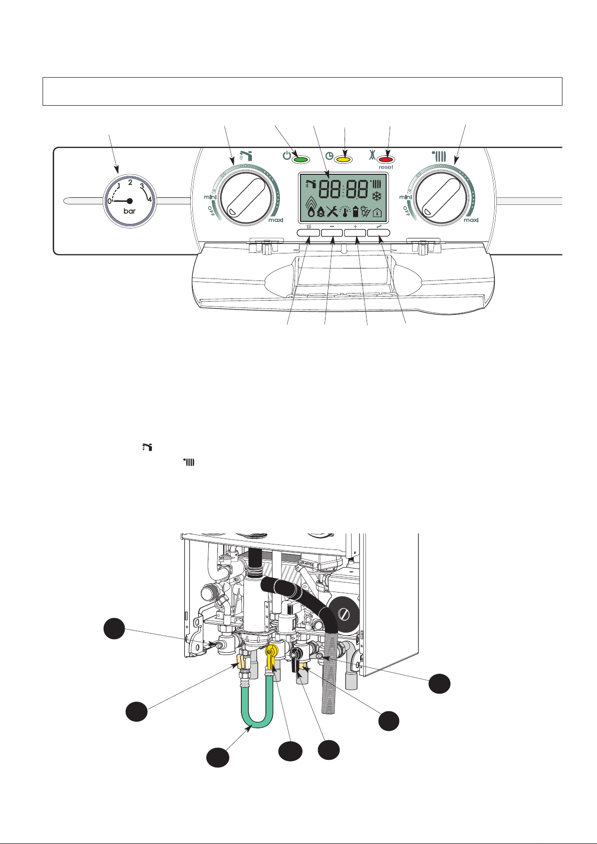
Control panel (Fig. 1)
16.- Pressure gauge
26.- Display
27.- On/off push button and power on indicator light
28.- Programming button - domestic hot water temperature
holding function -yellow indicator light
29.- Reset push button and red indicator lock-out light
30.- DHW control knob and temperature setting
31.- Central Heating control knob and temperature setting
32.- Menu button
33.- Reducing button
34.- Increasing button
35.- Setting button
27
32
26
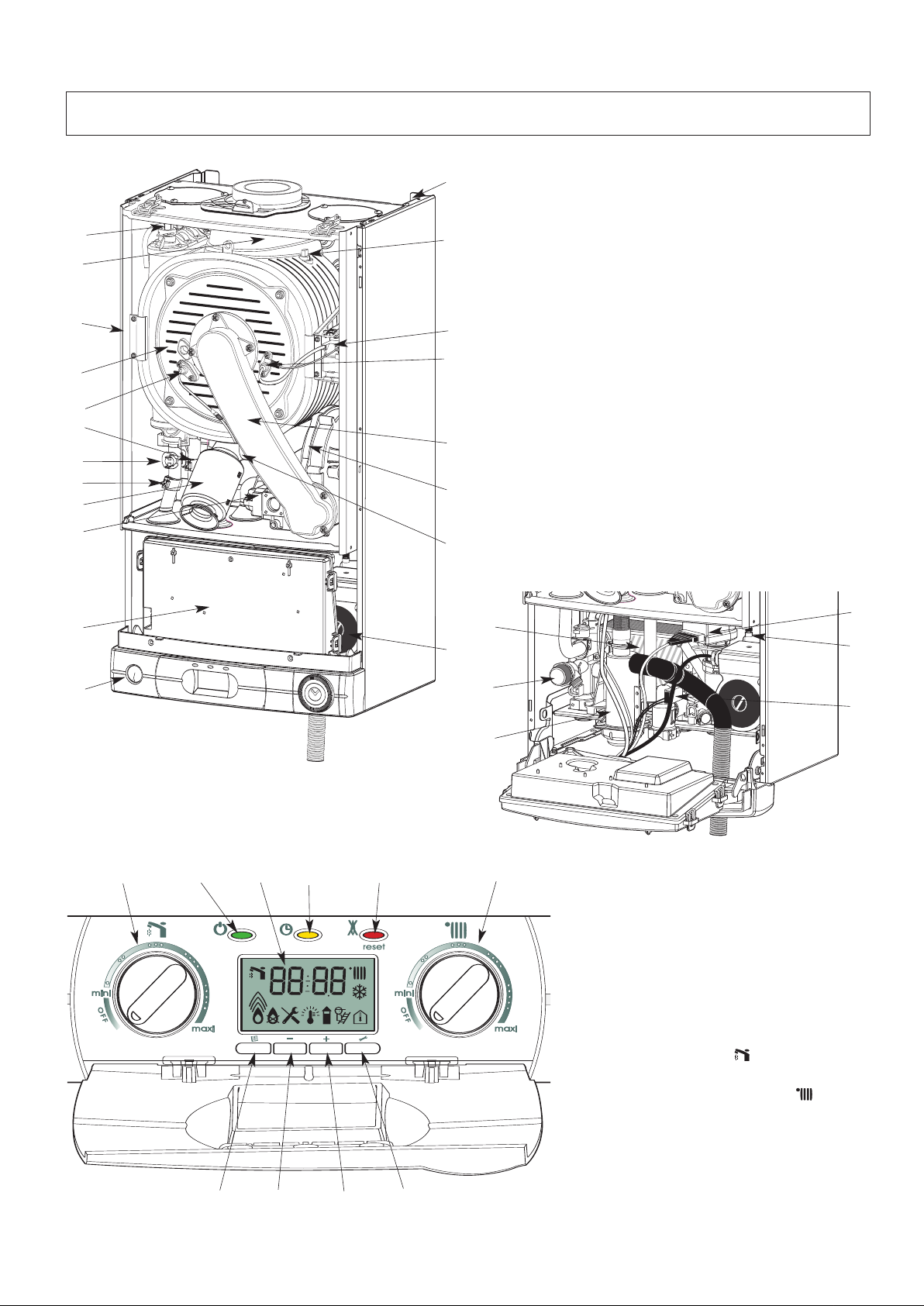
Connecting bracket
Taps shown in Open position (Fig. 2)
39 : Gas service tap
40 : Water service tap
41 : Central heating flow isolating valve
42 : Central heating return isolating valve
43 & 44: Filling taps
45 : Filling loop
28
33
34
29
35
31
41
43
Fig. 2
45
39
42
44
40
5
2. How to use
+
+
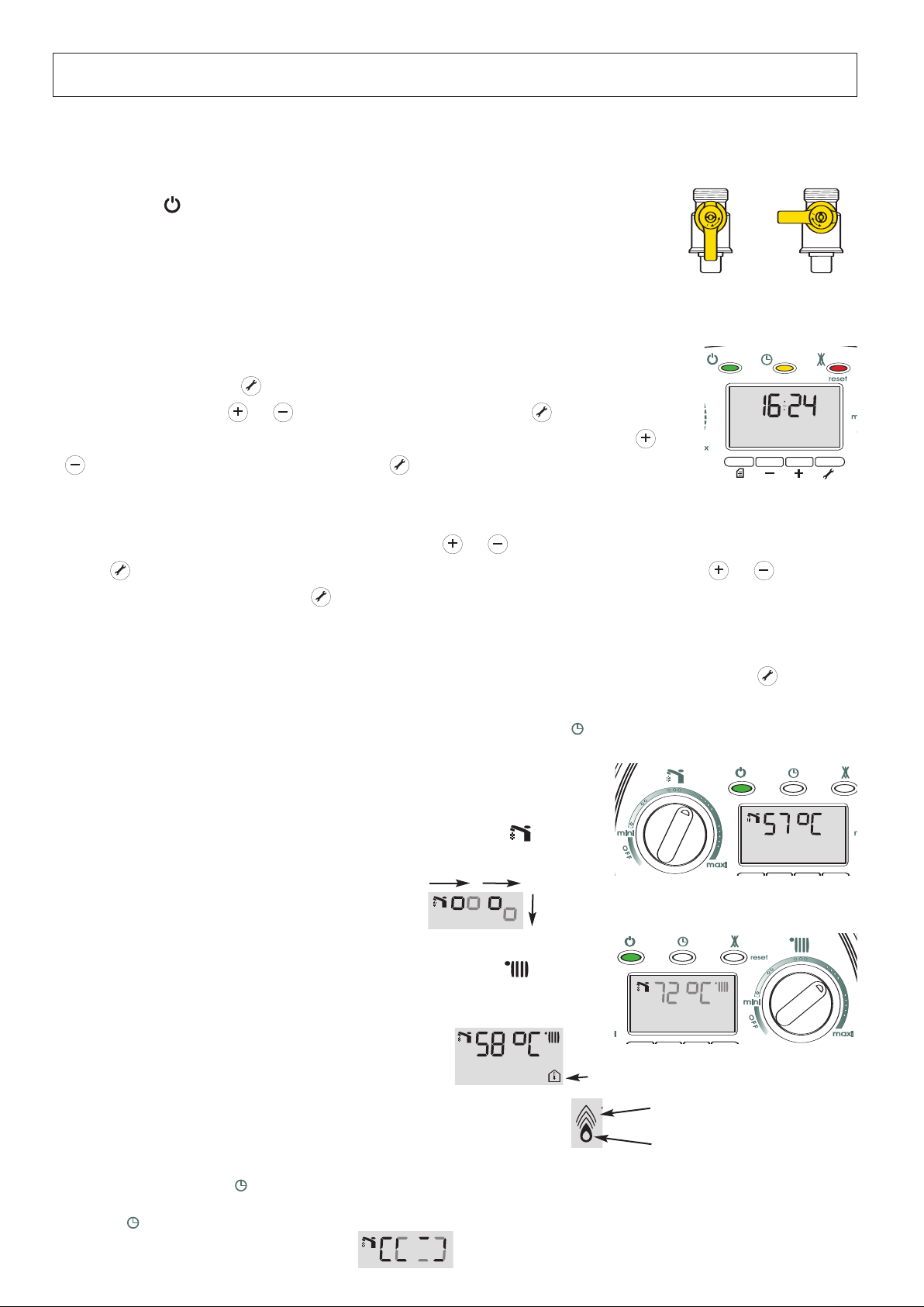
Switching on and filling instructions
. Check the pressure in the central heating system is above 0.7 bar and below 1.5 bar with the pressure gauge 16(fig.1),
1
should it be neccessary to re-pressurise the system,ensure the filling loop
the pressure gauge will now start to rise, once the pressure reads 1.0 bar, close the filling taps and disconnect the filling loop.
2. Check that the gas service tap is opened at the gas meter and the main power is on. Green
indicator
. Open the gas tap
3
4. The boiler is now ready to use.
NOTE: I
Setting the time and programming the domestic hot water exchanger temperature holding function
The time is set using the buttons located under the display panel.
Pressing the
can be adjusted using the or buttons. Pressing the
hour value and causes the minutes value to flash. This can now be adjusted by pressing the or
start time for the hot water exchanger temperature holding function now flashes on the display.
There are 2 possibilities:
- either you wish to modify the setting. In this case, press the or buttons to modify the hour then press the
button to validate the hour, causing the minutes value to flash. This can then be adjusted using the or buttons,
then validated using the
function is set. Follow the same procedure to set the programming end time for the hot water exchanger temperature holding
27 Power ON
fig.2).
39(
f the boiler is left off for a long time, some air in the gas pipe can hinder the first lighting
attempts. (please refer to Section 19 Incorrect Function, page 47)
setting button once for more than 5 seconds causes the hour value to flash. This
setting button again validates the
buttons then validated using the
setting button . The programming start time for the hot water exchanger temperature holding
setting button . The time is now set and the programming
45 (fig. 2) is attached, open the filling taps 43 & 44,
OPEN CLOSED
setting
function.
- or you wish to retain the original setting (6 a.m. - 11 p.m.). In this case, validate by pressing the
the time is set in order to end programming and exit the menu.
N.B. The temperature holding programming function is only activated if the button is pressed (indicator lit)
N
OTE:THIS IS NOT A TIMER FOR CH CONTROL
DHW mode
Turn the control knob 30 between min and max. During the adjustment, flashes.
The flashing goes on for a while after the adjustment, then the display indicates the time.
When DHW is drawn, the display indicates the following:
Heating mode
Turn the control knob 31 between min and max. During the adjustment flashes.
The flashing goes on for a while after the adjustment, the display will then indicate:
- the central heating flow temperature if the room thermostat is calling for heat.
- the time if the room thermostat is OFF.
Room thermostat request symbol
setting button twice once
BURNER ON and output level
The flame digits will increase or decrease depending on the output.
"Programming" button: button not activated, the domestic hot water exchanger temperature holding function is
activated permanently.
"Yellow" button activated, the temperature holding function respects the programme (11 p.m. OFF, 6 a.m. ON, original
setting). The display indicates the following
6
Flame digit
Burner ON
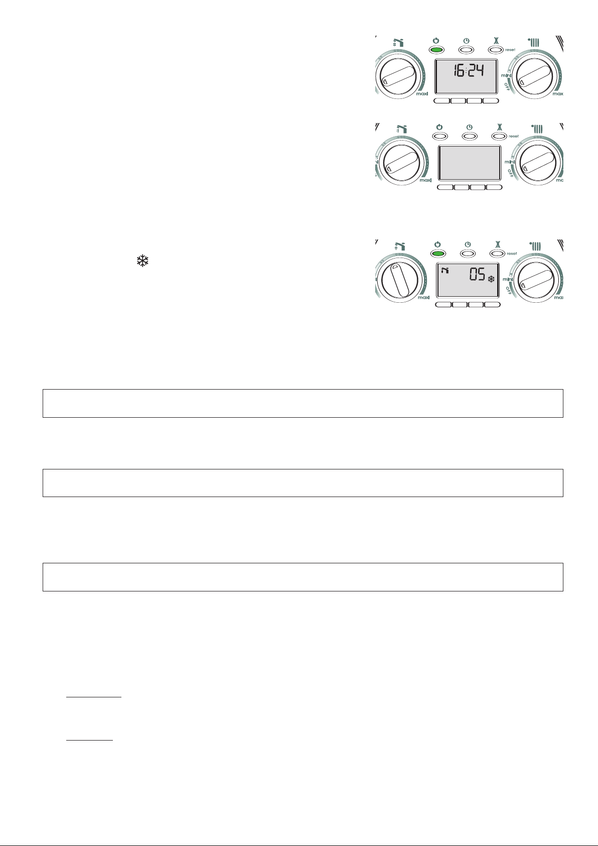
Stand-by mode
Turn the control knobs 30 and 31 to the OFF position to deactivate the DHW
and Heating. Leave the ON/OFF button On with the green light on.
uring the stand-by mode the display indicates the time, anti-seizing and anti-
D
freezing will be active.
Switch OFF
Press the button ON/OFF.
During this mode the boiler will not operate, but is still connected to the mains.
Anti-freezing mode
urn the control knobs 30and 31 to OFFto switch off the heating and hot water
T
functions. Leave the On/Off button on with the green light on.
When the anti-freeze comes on, the corresponding code is displayed with the
nowflake pictogram .
s
The two possible codes are 05 (anti-freeze - pump only) or 06 (anti-freeze -
burner).
05: When this mode is active, the circulating pump operates for one
minute and the diverter valve switches every 23 hours.
Caution: in this mode, the room thermostat anti-freeze function is
inoperative.
Boiler anti-freeze function: the pump starts at 8°C
the burner starts at 3°C
3. Maintenance
Your boiler will work more reliably and efficiently if regularly serviced. We recommend an annual service check. The service
history of the appliance will be marked in the Sercice Interval Record (Section 25, page 61).
4. Guarantee
The manufacturer`s guarantee is for 12 months from the date of purchase. The guarantee is voidable if the appliance is not
installed in accordance with the recommendations made herein or in a manner not approved by the manufacturer. To assist us
in providing you with an efficient after sales service, please return the guarantee registration card enclosed with the boiler without delay.
5. Practical information
Cleaning the casing and control panel
Should it be necessary to clean the casing and control panel. do so only with a soft damp cloth, do not use any spray polishes
or cleaners.
Precaution to avoid freezing
We recommend you contact your installer or local service centre for further advice on the actions to be taken to avoid the
system freezing.
DHW system
•
Turn off the main cold water supply and drain the boiler :
- Open a hot water tap
- Unscrew the cold water inlet tail
system
CH
•
Chose one of the following solutions :
- 1) Drain completely the Central Heating system
- 2) Protect the Central Heating system with anti freeze chemical products and verify the concentration periodically
C)
- 3) Leave the Heating mode switched on and set the room thermostat to anti-freeze mode (between 5 and 10
- 4) Leave your boiler in stand by mode, the anti-freeze device will switch on the pump and the burner if necessary.
°
7
3
6
9
1
2
11
22
33
44
55
66
77
88
99
1010
1111
1212
1313
1414
1515
1616
1717
1818
1919
2020
2121
2222
2323
2424
99
66
1212
I
6. Setting the time clock
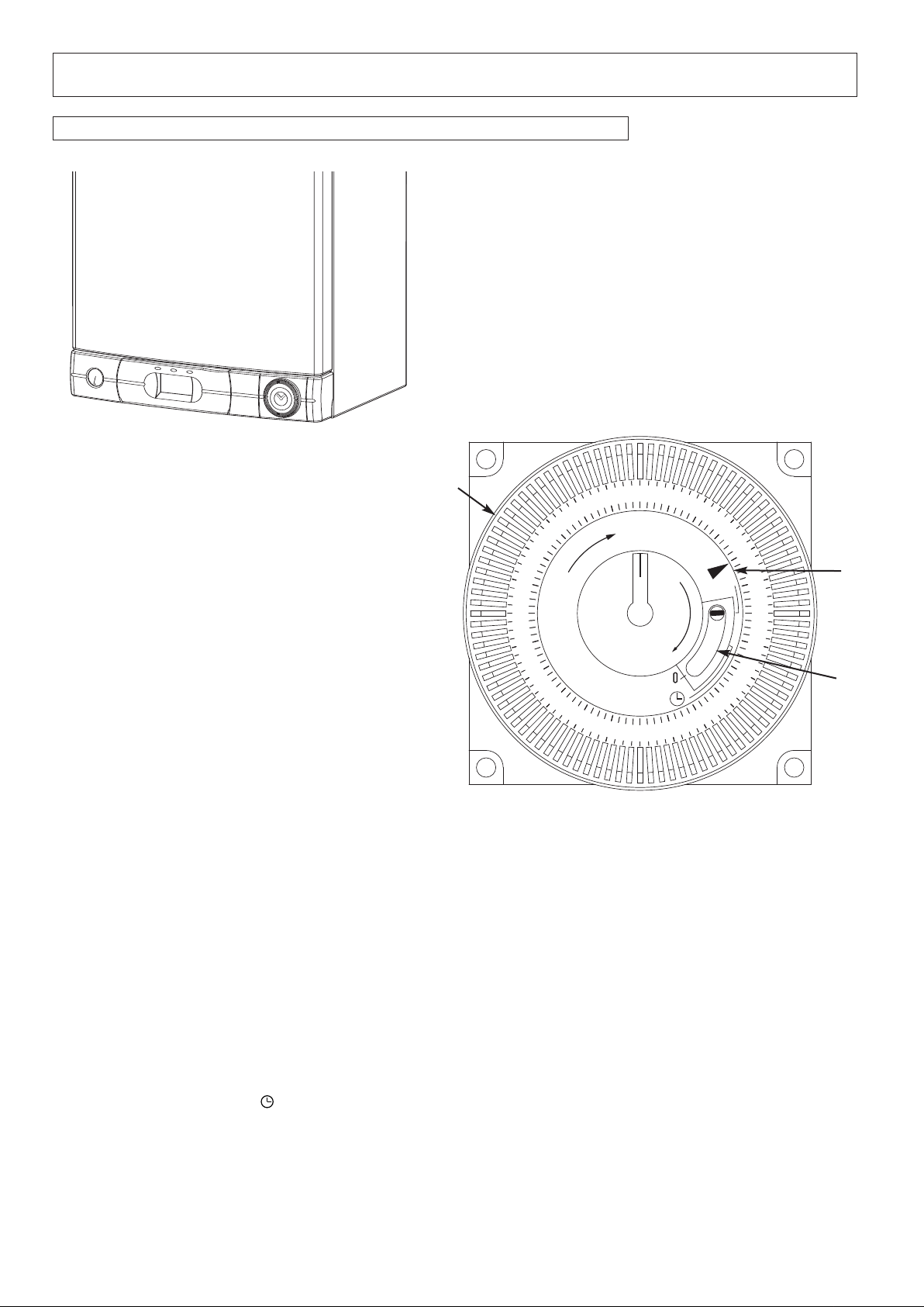
6.1 Setting the mechanical clock
Fig. 3
A
Fig. 4
1. General layout
The mechanical clock covers a 24 hour period. Each tappet represents 15 minutes A (Fig. 4). An override switch is located on
B (Fig 4).
symbol to control the central heating by the clock. Put the switch
B to «I» to select
the clock
2. To set the time
To set the time of day, grasp the outer edge of the dial and turn slowly clockwise until the correct time is lined up with the arrow
C (Fig. 4).
3. To Set the "On" and "Off" times
The clock uses a 24hours system. e.g. 8 = 8.00 am and 18 = 6.00 pm "ON" periods are set by sliding all tappets between the
"ON" time and the "OFF" time to the outer edge of the dial.The tappets remaining at the centre of the dial are the "OFF"
periods.
4. For operation
Put the selector switch B to the
permanent operation or to «0» to turn the central heating off permanently.
C
B
8
P
r
o
g
.
h
m
Day
M
anual switch
Summer and
w
inter time
s
etting
R
eset
Enter
weekday/s
E
nter
t
he hours
Week-
d
ays
f
lash
E
nter
m
inutes
E
nter
s
witching
times
I
mput
t
ime
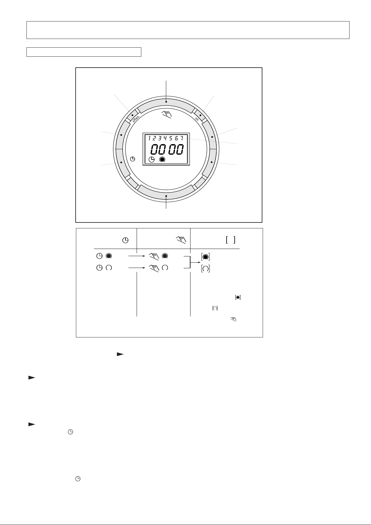
Automatic Manual Continuous
Operation Operation Operation
The switching If the current You can only
times corres- switching mode is return to automatic
pond to the changed manually, mode from the
program the next switching continuously-ON
entered. time will be and continuously-
carried out auto- OFF switching
matically again modes by
according to the pressing the " "
entered switching key.
program.
= ON = ON = Continuously ON
= OFF = OFF = Continuously OFF
6. Setting the time clock (continued)
6.2 Setting the Digital Clock
Operating the time switch
The steps marked with the symbol “ ” are necessary to carry out a switching program.
Preparing for Operation
Activate the “Res” switch (=RESET) to reset the time switch to its default setting (activate using a pencil or similar pointed
instrument). Do this:
- every time you wish to “reset” the time switch
- to erase all switching times and the current time of day.
After approximately two seconds the following display appears:
Enter current time and weekday
- Keep the “ ” button pressed down
During the summer time period press the +/- 1h button once.
Enter the hour using the “h” button
Enter the minutes using the “m” button
Enter the day using the “Day” button
1 = “Monday”..............7 = Sunday
- Release the “ ” button.
9

6. Setting the time clock (continued)
Entering the switching times
ou have 20 memory Iocations available. Each switching time takes up one memory location.
Y
eep pressing the “Prog” button until a free memory location is shown in the display “– –:– –”.
K
rogramme ON or OFF with the “ ” button :
P
“ ”= OFF; “ ”= ON
Enter the hour using “h”
Enter the minutes using “m”
If a switching command is to be carried out every day (1 2 3 4 5 6 7) then store using the “ ” button, otherwise select the
day(s) it is to be carried out by using the “Day” button.
When the day seIection is left bIank, the programmed switching instruction operates at the same time every day
2 3 4 5 6 = Monday – Saturday
1
2 3 4 5 = Monday – Friday
1
7 =Saturday – Sunday
6
Selection of single days: 1 = Mon. .............. 2 =Tues.
Save the switching time with the “ ” button.
The time switch enters the automatic operating mode and displays the current time of day.
Begin any further entry of a switching time with the “Prog” switch. If your entry is incomplete, the segments not yet selected
will blink in the display. After programming is completed, and you return the time clock to the current time display with the “
” button, the time clock will not activate any switching instruction required for the current time. You may need to manually
select the desired switching state with the “ ” button. Thereafter, as the unit encounters further switching instructions in
the memory in real time, it will correctly activate all subsequent switching instructions.
Manual Override Switch “ ”
With the “ ” you can change the current setting at any time. The switching program already entered is not altered.
Reading the programmed switching times
Pressing the “Prog” button displays the programmed switching times until the first free memory location appears in the display
“– – : – –”.
If you now press the “Prog” button once again, the number of free memory Iocations will be displayed, e.g. “
locations are occupied, the display “
Changing the programmed switching times
Press the “Prog” button repeatedly until the switching time you want to change is displayed. You can now enter the new data. See
Entering the switching times”.
point “
Notes on storing switching times:
If you end your entry of the switching times by pressing the “Prog” button, then the switching time you have entered will be stored
and the next memory location displayed.
In addition, a complete switching command is stored
pressed. The time switch then enters the automatic operating mode and displays the current time again.
Deleting individual switching times
Press the “Prog” button repeatedly until the switching time you wish to delete is shown in the display. Then set to “– –” using the
“h” or “m” button and keep the “ ” button pressed down for around 3 seconds. The switching time is now erased and the current
time is displayed.
00” appears.
automatically after around 90 seconds provided no other button is
18”. If all memory
AM / PM time display
If you press the “+/-1h” and “h” button at the same time, the time display switches into the AM/PM mode.
10
3
6
9
12
7. Description
24
10
2
3
8
20
22
21
12
6
INSTALLER INSTRUCTIONS
- Steel chassis complete with expansion vessel
1
25
9
7
4
5
42
1.
2.- Sealed chamber
3.- Burner and heat exchanger assembly
4.- Air / gas connection
- 24 V modulating fan
5.
6.- Gas valve
- Ignition electrode
7.
8.- Ionisation probe
- Ignitor
9.
10.- Combustion products manifold
11.- Siphon
12.- Silencer
- Electrical box
13.
14.- Pump
15.- Secondary heat exchanger
16.- Pressure gauge
17.- Three way valve
18.- Automatic air vent
19 - Domestic hot water flowswitch
20.- Main exchanger inlet thermistor
21.- Main exchanger outlet thermistor
22.- Overheat sensor
23.- Central heating pressure relief valve
24.- Manual air vent with pipe
25.- Thermo fuse
13
16
Fig. 5
Fig. 7
30
27
32
26
33
28
34
29
35
14
15
23
11
Fig. 6
31
26.- Display
On/off push button and power on
27.indicator light
28.- Programming button - domestic hot
water temperature holding function yellow indicator light
29.- Reset push button and red indicator
locking light
30.- DHW control knob and temperature
setting
31.- Central Heating control knob and
temperature setting
32.- Menu button
33.- Reducing button
34.- Increasing button
35.- Setting button
17
18
19
11
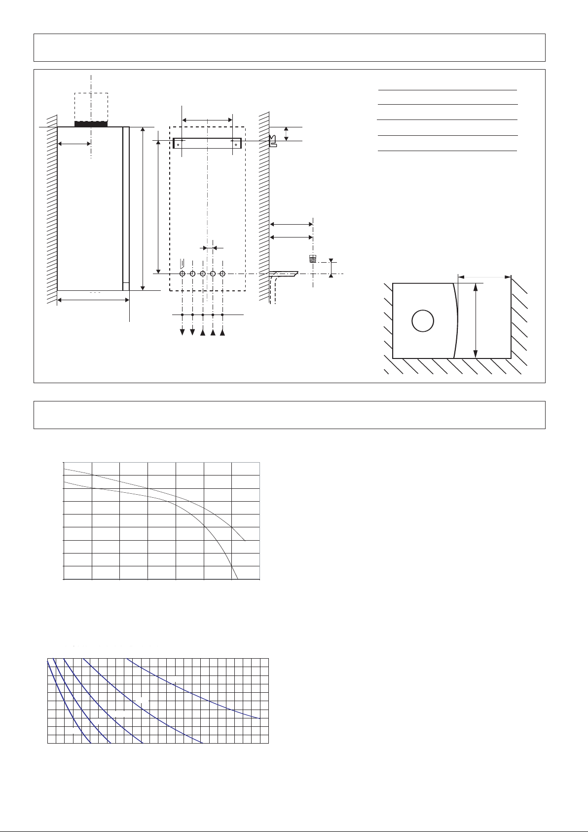
8. Dimensions
440
4
50 mini pour entretien
54 54 54 54
JKLMN
I
JKLMN
32
296
1
41
2
89
2
1
720
691,5
121,5
I
172,5
4,7
0
0.05
0
.1
0
.15
0.2
0.25
0.3
0.35
0
.4
0.45
0 200 400 600 800 1000 1200 1400
24 kW
30 kW
20 40 60
80 100 120
Pf
140 160 180 200 220 240
1,0
1,1
1,2
1,3
1,4
1,5
1,6
1,7
1,8
1,9
2,0
Capacité maximale de l'installation (en litres)
260
Pression à froid pour le circuit chauffage (en bar)
280
40°C
50°C
60°C
70°C
80°C
162
296 (24 kW)
360 (30/35 kW)
All dimensions in mm
afety valve C/H and condensate
I S
J
Heating flow
K
D.H.W. outlet
L
Gas supply
M
Cold water inlet
N
Heating return
With packaging :
24 kW : 37 kg
30 kW : 40 kg
minimum space required 450
390
Fig. 8
9. Hydraulic data
Pump Head Graph (15/50 & 15/60)
Pressure (bar)
Central heating initial pressure when cold (in bar)
12
System capacity chart
flow rate (l/hr)
Fig. 9
C litre
Fig. 10
The boiler is fitted with an automatic by-pass as standard.
The graph (Fig. 9) shows the development of the pressure
available in relation to flow (on exit from the boiler ∆T
C).
°
20
To ensure correct operation, the minimum flow of the
appliance must be 300 l/h. (Thermostatic taps closed).
Capacity of the installation.
The water heater is fitted with a pressurised expansion
vessel.
Volumes : 6 litres
Pressure: 0,7 bar.
The volume of the expansion vessel in a pressurised
appliance varies according to:
C
- the average operating temperature in
°
- the static height, which is the difference in metres
between the highest point of the appliance and the
expansion vessel axis).
The minimum cold filling pressure of the appliance is 1 bar
(recommended pressure between 1.2 and 1.7 bar).
The pressure of the expansion vessel should always be
greater than the static height (in metres) divided by 10.
E
E
10. Installation requirements
eference Standards
R
In the United Kingdom, the installation and initial start up of
the boiler must be by a CORGI Registered installer in
accordance with the installation standards curently in effect,
s well as with any and all local health and safety standards
a
i.e. CORGI.
In the Republic of Ireland the installation and initial start up of
the appliance must be carried out by a Competent Person in
accordance with the current edition of I.S.813 “Domestic Gas
Installations” and the current Building Regulations, reference
should also be made the the current ETCI rules for electrical
installation.
The installation of this appliance must be
in accordance with the relevant
requirements of the Local Building
egulations, the current I.E.E. Wiring
R
Regulations, the by-laws of the local water
authority, in Scotland, in accordance with
the Building Standards (Scotland)
Regulation and Health and Safety
document No. 635, “Elelectricity at Work
Regulations 1989” and in the Republic of
Ireland with the current edition of I.S. 813
and the Local Building Regulations (IE).
ust not be installed in a place likely to cause nuisance. It
m
must not be allowed to discharge into another room or space
such as an outhouse or closed lean-to.
ondensing boilers have a tendency to form a plume of water
C
vapour from the flue terminal due to the low temperature of the
flue gasses. The terminal should therefore be located with due
regard for the damage or discolouration that might occur to
buildings in the vicinity and consideration must also be given to
adjacent boundaries, openable windows should also be taken
into consideration when siting the flue.
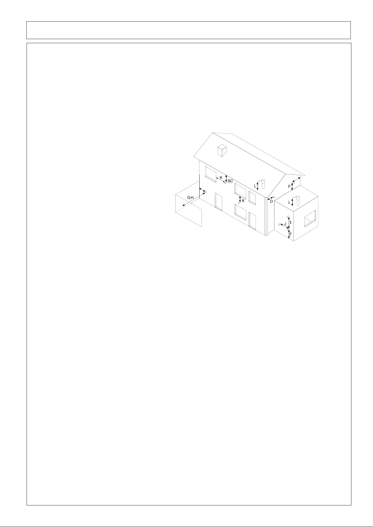
The minimum acceptable clearances are shown below:
Fig. 11
C.O.S.H.H.
Materials used in the manufacture of this
appliance are non-hazardous and no
special precautions are required when servicing.
Codes of Practice
Installation should also comply with the following British
Standards Codes of Practice:
BS 7593:1992 Treatment of water in domestic hot
water central heating systems
BS 5546:1990 Installation of hot water supplies for
domestic purposes
BS 5440-1:2000
Flues
BS 5440-2:2000 Air Supply
BS 5449:1990
Forced ciculation hot water systems
BS 6798:2000 Installation of gas fired hot water
boilers of rated input not exceeding
70kW
BS 6891:1989 Installation of low pressure gas pipe up
to 28mm
BS 7671:2001 IEE Wiring Regulations
BS 4814:1990 Specification for expansion vessels
BS 5482:1994 Installation of L.P.G.
and in the Republic of Ireland in accordance with the
following codes of practice
I.S. 813 Domestic Gas Installations
- A Directly below an opening, window, etc 300 mm
- B Below gutters, soils pipes or drain pipes 75 mm
- C Below eaves 200 mm
- D From vertical drain pipe or soil pipe 75 mm
- E From internal or external corner 300 mm
- F Above ground on a public walkways or patio 2100 mm
- G From a surface facing the terminal 2500 mm
- H From a terminal facing the terminal 2500 mm
- I Vertically from a terminal on the same wall 1500 mm
- J Horizontally from a terminal on the same wall 300 mm
- K Horizontally from an opening window
300 mm
- L Fixed by vertical flue terminal
NOTE: THE
FLUE
CAUSE A NUISANCE
.
BE INSTALLED IN A PLACE LIKELY TO
NOT
MUST
It may be necessary to protect the terminal with a guard, if this is
the case it will be necessary to purchase a stainless steel terminal
guard. Reference should be made to the Building Regulations for
guidance.
Ventilation
The room in which the boiler is installed does not require specific
ventilation.
If it is installed in a cupboard or compartment
permanent ventilation is not required for cooling purposes.
Avoid installing the boiler where the air inlet can be polluted
by chemical products such as chlorine (swimming pool area),
or ammonia (hair-dresser), or alkalin products (launderette)
Flue
Detailed information on flue assembly can be found in Section
12 “Connecting the flue”.
The boiler must be installed so that the flue terminal is
exposed to the free passage of external air at all times and
Gas Supply
The gas installation and soundness testing must be in
accordance with the requirements of BS 6891. Ensure that
the pipe size is adequate for demand including other gas
appliances on the same supply.
13

10. Installation requirements (continued)
Electrical Supply
he appliance requires an earthed 230V - 50 Hz supply and
T
must be in accordance with current I.E.E. It must also be
ossible to be able to completely isolate the appliance
p
electrically. Connection should be via a 3 amp fused doublepole isolating switch with contact separation of at least 3 mm
on both poles. Alternatively, a fused 3 Amp. 3 pin plug and
unswitched socket may be used, provided it is not used in a
room containing a bath or shower. It should only supply the
appliance.
The boiler is suitable for sealed systems only. The maximum
orking pressure for the appliance is 6 bar. All fittings and
w
pipework connected to the appliance should be of the same
standard. If there is a possibility of the incoming mains
pressure exceeding 6 bar, particularly at night, then a
uitable pressure limiting valve must be fitted.
s
The boiler is designed to provide hot water on demand to
multiple outlets within the property. If there is a requirement
for greater demands, for example if the property has several
bathrooms and cloakrooms, a vented or unvented hot water
storage system may be used.
Showers
Any shower valves used with the appliance should be of a
thermostatic or pressure balanced type. Refer to the shower
manufacturer for performance guidance and suitability.
Flushing and Water Treatment
The boiler is equipped with a stainless steel heat exchanger.
The detailed recommendations for water treatment are given
in BS 7593:1992 (Treatment of water in domestic hot water
central heating systems); the following notes are given for
general guidance;
If the boiler is installed on an existing system, any
unsuitable additives must be removed;
Under no circumstances should the boiler be fired before the
system has been thoroughly flushed; the flushing procedure
must be in line with BS7593:1992.
We highly recommend the use of a flushing detergent
appropriate for the metals used in the circuit. These include
cleansers produced by Fernox and BetzDearborn, whose
function is to dissolve any foreign matter that may be in the
system;
In hard water areas or where large quantities of water are in
the system the treatment of the water to prevent premature
scaling of the main heat exchanger is necessary.
The formation of scale strongly compromises the efficiency of
the thermic exchange because small areas of scale cause a
high increase of the temperature of the metallic walls and
therefore add to the thermal stress of the heat exchanger.
Demineralised water is more aggressive so in this situation it
is necessary to treat the water with an appropriate corrosion
inhibitor.
Any treatment of water by additives in the system for frost
protection or for corrosion inhibition has to be absolutely
suitable for all the metals used in the circuit.
The use of a corrosion inhibitor in the system such as Fernox
B-1, BetzDeaborn Sentinel X100 or Fernox System
M
Inhibitor is recommended to prevent corrosion (sludge)
amaging the boiler and system;
d
If anti-freeze substances are to be used in the system, check
carefully that they are compatible with the metals used in the
circuit.
MTS suggests the use of suitable anti-freeze products such
as Fernox ALPHI 11, which will prevent rust and incrustation
taking place.
Periodically check the pH of the water/anti-freeze mixture of
the boiler circuit and replace it when the amount measured is
out of the range stipulated by the manufacturer ( 7 < pH < 8).
O NOT MIX DIFFERENT TYPES OF ANTI-FREEZE
D
In under-floor systems, the use of plastic pipes without
protection against penetration of oxygen through the walls
can cause corrosion of the systems metal parts
(metal piping, boiler, etc), through the formation of oxides
and bacterial agents.
To prevent this problem, it is necessary to use pipes with an
“oxygen-proof barrier”, in accordance with standards DIN
4726/4729
system separate by installing heat exchanger
with a specific system water treatment.
IMPORTANT
Failure to carry out the water treatment procedure will
invalidate the appliance warranty.
System Controls
The boiler is electrically controlled and is suitable for most
modern electronic time and temperature controls. The
addition of such external controls can be beneficial to the
efficient operation of the system. The boiler connections for
external controls are 12V DC and so only controls of 12V DC
that have voltage free contacts should be used. (Section 13
Electrical Connections - page 25).
Location
The boiler can be installed on any suitable internal wall.
Provision must be made to allow the correct routing of the flue
and siting of the terminal to allow the safe and efficient
removal of the flue products. A compartment or cupboard may
be used provided that it has been purpose-built or modified for
the purpose. It is not necessary to provide permanent
ventilation for cooling purposes. Detailed recommendations
are given in BS 5440 pt 2. If it is proposed that it is installed in
a timber framed building then reference should be made to
British Gas Document DM2, or advice sought from CORGI.
Where a room sealed appliance is installed in a room
containing a bath or shower, the appliance and any
electrical switch or appliance control, utilising mains
electricity should be situated specifically in accordance
with current IEE Wiring Regulations.
For unusual locations, special procedures may be necessary.
BS 6798:2000 gives detailed guidance on this aspect.
Condensate Discharge
The condensate discharge hose from the boiler must have a
continuous fall of 2.5oand must be inserted by at least 50mm
. If pipes of this kind are not used, keep the
s of those
14
10. Installation requirements (continued)
nto a suitable acid resistant pipe - e.g. plastic waste or
i
overflow pipe. The condensate discharge pipe must have a
minimum diameter of 22mm, must have a continuous fall and
preferably be installed and terminated to prevent freezing.
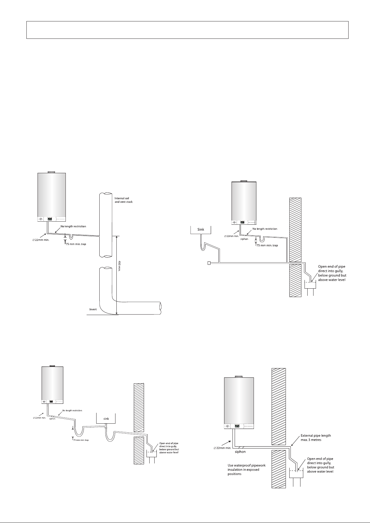
he discharge pipe must be terminated in a suitable position:
T
) Connecting into an internal soil stack (at least 450mm
i
above the invert of the stack). A trap giving a water seal
of at least 75mm must be incorporated into the pipe run,
there also must be an air break upstream of the trap.
ii) Connecting into the waste system of the building such as
a washing machine or sink trap. The connection must be
pstream of the washing machine/sink. If the connection
u
is down stream of the waste trap then an additional trap
1. Internal termination of condensate drainage pipe to
internal stack
iving a minimum water seal of 75mm and an air break
g
must be incorporated in the pipe run, as above.
iii) Terminating into a gully, below the grid level but above
the water level.
v) Into a soakaway.
i
If any condensate pipework is to be installed
N
O
:
TE
externally then it should be kept to a minimum and be
insulated with a waterproof insulation and have a continuous
fall. The total length of external pipe used should not exceed
3 metres.
ome examples of the type of condensate terminations can
S
be found below.
2. External termination of condensate drainage pipe via
internal discharge branch (e.g. sink waste) and condensate
siphon
3. External termination of condensate drainage pipe via
internal discharge branch (e.g. sink waste - proprietary fitting).
4. External termination of condensate drainage pipe via
condensate siphon
15

11. Installing the boiler
lease check that you are familiar with the installation requirements before commencing work (Section 10).
P
The installation accessories described in the following list are included in the boiler packaging:
Hanging bracket
-
- A paper template (showing the dimensions of the boiler with 5 mm side clearances)
- Connection tails and valves
- Screws and washers
- Connection washers
- Installation, Servicing and Operating Instructions
Method of positioning the boiler on the wall.
The paper template can be used to ensure the correct positioning of kitchen cabinets etc. It also details the commissioning
instructions.
The paper template has to be fixed to the wall and used to locate the position of the hanging bracket and the centre for the flue
hole.
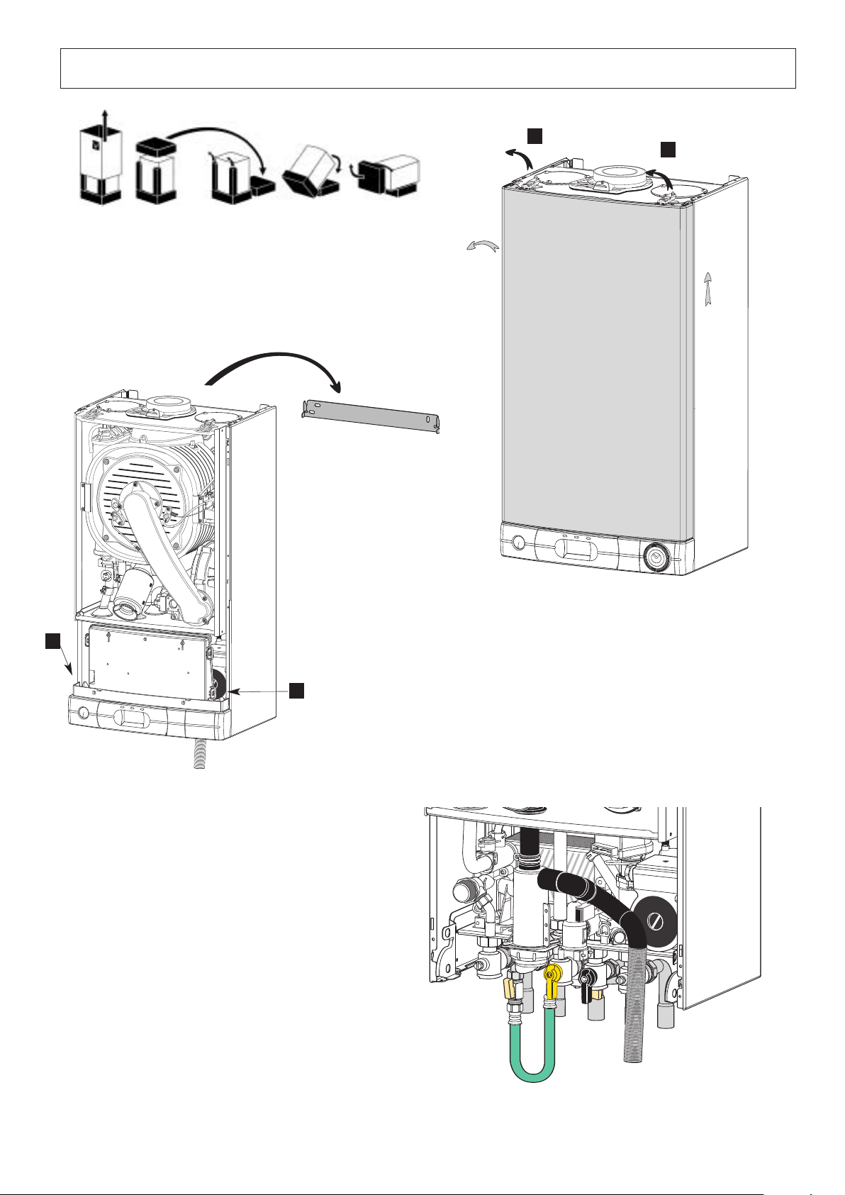
Drill and plug the wall and secure the hanging bracket using the screws provided. Remove the boiler from its packaging as
shown in Fig. 17 and unscrew the two clamp locking bolts
Place the boiler on the wall on the hanging bracket (Fig. 14).
NOTE: TH
Connecting the boiler to the system
- Remove the boiler casing as described in Section 18.
- Push in the tabs “P” (Fig. 14) on either side of the boiler and pivot the electrical box forward to gain access to the valve
- Remove the caps and connect the boiler to the taps using washers provided in the plastic bag.
E APPLIANCE MUST NOT BE FITTED ON A COMBUSTIBLE WALL SURFACE
connections
4 x fibre washers for the C/H flow and return, hot water outlet and cold water inlet connections
1 x rubber washer for gas connection
A and remove the casing (Fig. 13).
.
Safety valve discharge
The pressure relief valve tube is made of copper. It should terminate below the boiler safely outside the premises. Care should
be taken that it does not terminate over an entrance or window or where a discharge of heated water could endanger
occupants or passers by.
Fill the Central Heating and DHW system and bleed air from system as described in Section 14.
The system should be carefully checked for leaks, as frequent refilling could cause premature system corrosion or
unnecessary scaling of the heat exchanger. The pipe from the siphon (11 Fig. 5) should be connected to a drain as described
in the relevant Brittish regulations.
Pay special attention to not bend the condensate silicone drain pipe such as the flow will be interrupted. Please use exclusively
drain pipe material compatible with condensate products. (refer to
The condensate flow can reach 2 litres / hour; because of the acidity of the condensate products (Ph close to 2), take care
before operation.
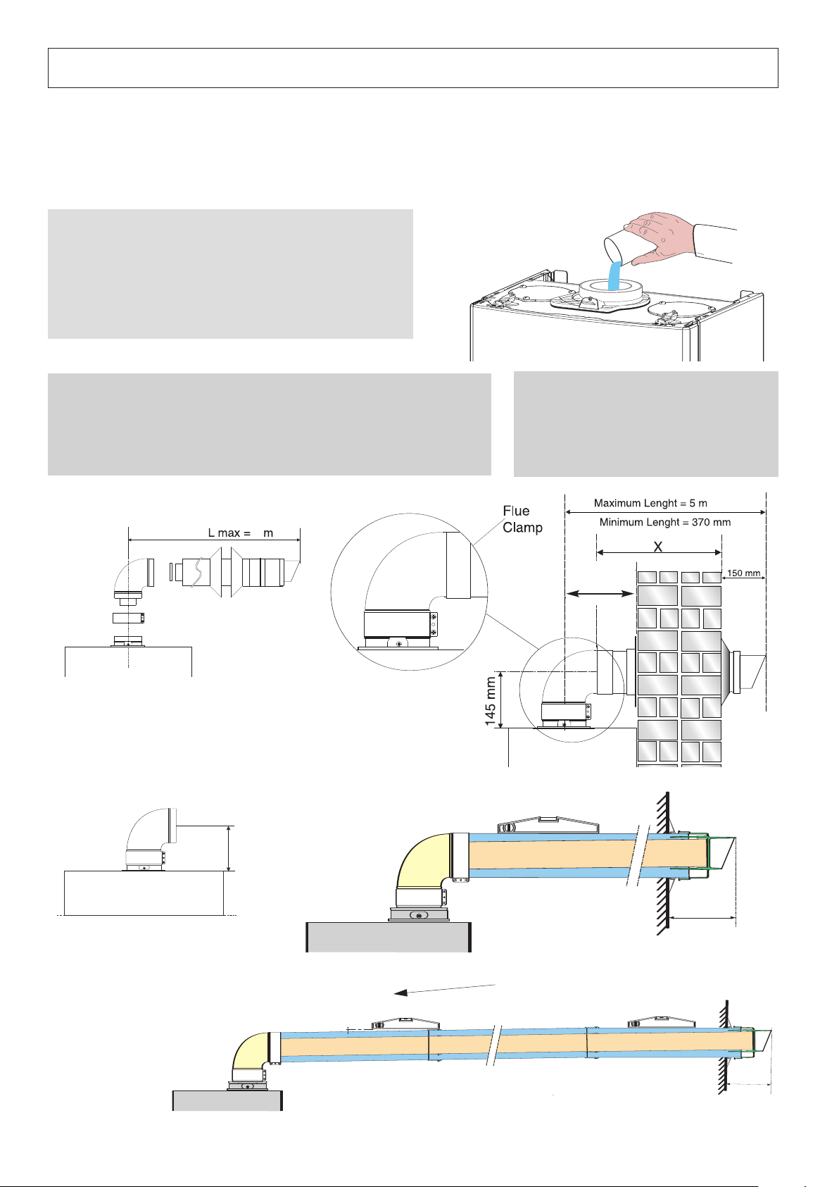
Fitting the Horizontal Flue
Attention ! Before starting the boiler, the siphon (11 Fig. 5) must be filled with water. Before fitting the flue l onto the
boiler, pour 1/4 litre of water in the exhaust pipe as shown in Fig. 16.
Instructions on fitting the flue can be found in Section 12.
IMPORTANT!!
Use only the specific condensation flue kit supplied by MTS.
BS 6798 : 2000)
16
3
6
9
12
1
2
3
6
9
12
11. Installing the boiler (continued)
ig. 12
F
A
A
Fig. 13
P
P
Fig. 14
15
Fig.
17
150 mm
* pente 5 mm par mètre
150
mm
* pente
5
12. Connecting the Flue
118
The boiler should only be installed with a flue system supplied by MTS (GB) Limited.
These kits are supplied separately to the appliance in order to respond to different installation solutions. For more information
with regard to the inlet/outlet accessories consult the accessory catalogue. The boiler is supplied ready for connection to a
oncentric flue system.
c
N
OTE:SEE PAGE 24 FOR MAXIMUM AND MINIMUM FLUE RUNS (TABLES A, B AND C)
IMPORTANT!!
BEFORE CONNECTING THE FLUE, ENSURE THAT 1
WATER HAS BEEN POURED INTO THE EXHAUST CONNECTION
TO FILL THE CONDENSATE TRAP
T
RAP BE EMPTY THERE IS A TEMPORARY RISK OF FLUE
GASSES ESCAPING INTO THE ROOM
(FIG. 16). SHOULD THE
.
/4
LITRE OF
ig. 16
F
Warning
The exhaust gas ducts must not be in contact with or close to inflammable
material and must not pass through building structures or walls made of
inflammable material.
When replacing an old appliance, the flue system must be changed.
Ø 60/100 mm
Fig. 17
Installation without extension
Important
Ensure that the flue is not blocked.
Ensure that the flue is supported and
assembled in accordance with these
instructions.
c162
18
Installation with extension
slope
slope 5 mm per metre
Fig. 18
 Loading...