

Page 1
ARB COMBINATION WINCH/NON-WINCH BULL BARS TO SUIT FORD
F250/350 PICKUPS 2000-2004 AND 2005 MODELS ON.
PRODUCTS No. 3436030/40
FITTING KITS No.6171871, 6171873,
6171926 (SUPP. KIT FOR WINCH FITMENT 3436040
ONLY)
WARNING
FOR VEHICLES EQUIPPED WITH SRS AIRBAG
WHEN INSTALLED IN ACCORDANCE WITH THESE INSTRUCTIONS, THE FRONT
PROTECTION BAR DOES NOT AFFECT OPERATION OF THE SRS AIRBAG.
TAKE NOTE OF THE FOLLOWING:
• THIS PRODUCT MUST BE INSTALLED EXACTLY AS PER THESE INSTRUCTIONS USING
ONLY THE HARDWARE SUPPLIED.
• IN THE EVENT OF DAMAGE TO ANY BULL BAR COMPONENT, CONTACT YOUR
NEAREST AUTHORISED ARB STOCKIST. REPAIRS OR MODIFICATIONS TO THE
IMPACT ABSORPTION SYSTEM MUST NOT BE ATTEMPED.
• DO NOT USE THIS PRODUCT FOR ANY VEHICLE MAKE OR MODEL, OTHER THAN
THOSE SPECIFIED BY ARB.
• DO NOT REMOVE LABELS FROM THIS BULL BAR.
• THIS PRODUCT OR ITS FIXING MUST NOT BE MODIFIED IN ANY WAY.
Note :
1 These winch bumpers are suitable for Warn 10, 12, 15, and 16500lb
winches.
Tools Required
Metric Spanner and Socket set Phillips head screwdriver,
Dia 12.5mm & 10mm drill bits 13mm capacity electric drill.
Plastic trimming cutting tool Allen (Hex) Key Set
Sikaflex - black
13/12/05 Page 1 of 12 3783101
If you have any queries regarding the installation of this product please contact the distributor from whom it was purchased, or alternatively the ARB office in your state.
WA: (08) 9244 3553 NSW: (02) 9821 3633 ACT: (02) 6280 7475 SA: (08) 8244 5001 QLD: (07) 3872 3872 NT: (08) 8947 2262 TAS: (03) 6331 4190
Head Office – ARB Corporation Ltd VIC: 42-44 Garden Street, Kilsyth, Victoria, 3137 Tel: (03) 9761 6622 Fax: (03) 9761 6807
Page 2

USE PART No QTY DESCRIPTION
MOUNT BRACKETS TO VEHICLE 3756655L 1 BRACKET BAR MOUNT LHS
3756655R 1 BRACKET BAR MOUNT RHS
3193695 4 PLATE
6151321 8 NUT M10 FLANGED
4581040 8 WASHER M10 X 3mm THICK
6151232 8 SCREW M10 X 30mm
4581048 8 WASHER M10 SPRING
6151305 6 CAGE NUT M12
4581049 6 M12 WASHER FLAT
4581050 6 M12 WASHER SPRING
6151255 6 SCREW M12 X 40
3199818 2 PACKER PLATE
TOW HOOK RELOCATION 4581049 6 M12 WASHER FLAT
4581050 6 M12 WASHER SPRING
6151255 6 SCREW M12 X 40
CONTROL BOX FITTMENT 3756775 1 CONTROL BOX BRACKET UNIV.
(If fitting winch) 3199790 1 PLATE TRIM FOR 16500LB CNTRL BX
6151364 2 SCREW CAP M10X30
4581291 2 WASHER FLAT M10 BZ
6151321 2 NUT M10 FLANGED
180302 8 CABLE TIE
NUMBER PLATE FITTMENT 6151017 2 BOLT M6 X 16mm
6151128 2 NUT FLANGE M6
6781408 1 TAPE DOUBLE SIDED
AIR DEFLECTOR FITTMENT 6151022 3 BOLT M8 x 25
4581063 3 WASHER FLAT M8 x 25.4 x 3
6151301 3 NUT M8 CAGED
6522045 1 PANEL AIR DEFLECTOR
4581046 3 WASHER M8 SPRING
TENSION STRAP 3756432 2 PLATE TENSION STRAP
6151255 4 BOLT M12 X 40mm
4581050 4 WASHER SPRING M12
4581049 8 WASHER FLAT M12
6151189 4 NUT M12
WINCH HOLE COVER FITTMENT 6151128 2 NUT FLANGE M6
(If not fitting winch) 6151256 2 SCREW M6 S/STEEL BUTTON HEAD
6191013 1 EXTRUSION WINCH COVER
6522048 1 PANEL WINCH COVER
6151046 2 WASHER M6
13/12/05 Page 2 of 12 3783101
Page 3

BAR TO MOUNT ASSEMBLY 6151255 6 BOLT M12 X 40mm
4581050 6 WASHER SPRING M12
4581049 12 WASHER FLAT M12
4581048 4 WASHER SPRING M10
6151189 6 NUT M12
6151321 4 NUT M10 FLANGED
6151232 4 BOLT M10 X 30mm
4581040 4 WASHER FLAT 3/8”
INDICATOR ASSY 6821151R 1 INDICATOR ASSY RHS
6821151L 1 INDICATOR ASSY LHS
6151308 4 SCREW SELF TAPPING
6821116 4 NUT NYLON PLUG
6821152 2 LOOM
180701 6 SCOTCH LOCKS
180302 4 CABLE TIE
SUPPLIMENTARY KIT 6171926 FOR WINCH RELIEF FOR 2005ON BAR ONLY
4681176 1 BRACE
3756735 1 BRACKET ANGLE
6151143
8 SELF DRILL SCREW
NOTE: Shipping brackets connecting bull bar
to pallet and associated fasteners are not
intended to be reused in fitted bar assembly.
13/12/05 Page 3 of 12 3783101
Page 4
ASSEMBLY SEQUENCE FOR WINCH BUMPER.
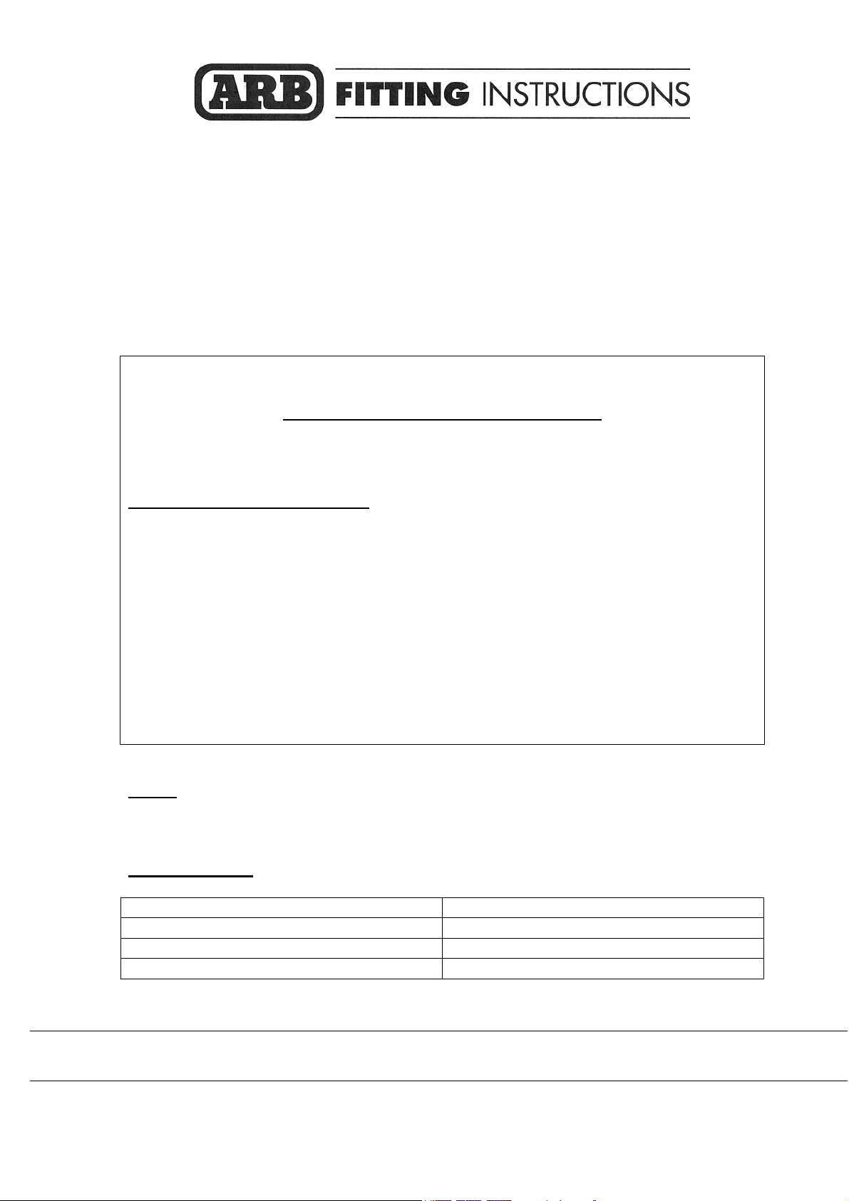
1. Fitting mounting brackets
Remove the bumper and two recovery
hooks.
Fit M12 cage nuts to slots on each mount
bracket as shown; make sure that they can
move laterally along the slots for
adjustment purposes later on.
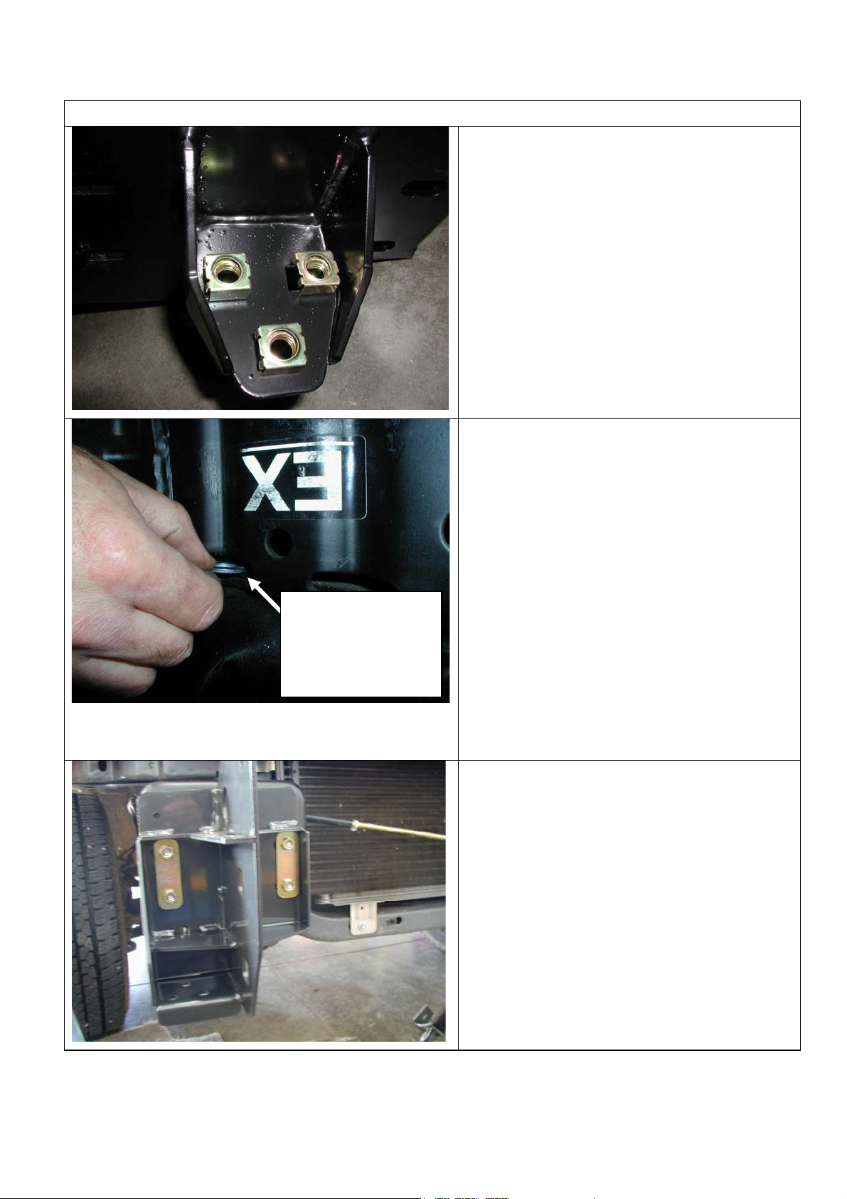
2. Sit mount brackets in position as shown in
step 3. Check that they sit flush against
flange, if not; the edge of chassis may be
bearing on weld on underside of welded
gusset. Fettle edge of chassis until it
clears bracket.
Slide packer into
chassis slot,
adjacent to
rearmost cage nut
position in gusset
There will be an air gap between the
rearmost under face of the gusset to the
lower inside face of chassis. Slide in
packer plate under rearmost bolt position to
support gusset. Using M12 x 40mm bolts,
flat and spring washers, fasten through the
holes in chassis end including packer,
where the recovery hook bolts were
removed.
Do not tighten bolts yet.
3. Fasten onto the end flanges on chassis
with M10 bolts, large 4mm thick washers,
M10 spring washers, nut plates and M10
flange nuts as shown, lightly tension.
Set the pitch between the flanges at
953mm inside, and locate symmetrically to
the center of the vehicle.
13/12/05 Page 4 of 12 3783101
Page 5

4. With the bull bar mounting brackets now in
place (but not tightened) bolt the tension
strap to the chassis using the hole next to
the horizontal slot.
Using the M12 bolt, flat washers, spring
washer and nut, bolt up the tension strap
as shown.
Note: The tension strap will need to be
bent out slightly, to pass alongside the bull
bar mounting bracket.
As the bolt is tightened the bracket will
bend slightly to allow the strap to sit flat
against the chassis.
5. Bend the end of the strap inward, as
shown, to allow the strap to sit against the
bull bar mounting bracket.
ROTATION
ORIGINAL
POSITION
Drill Dia
12.5mm hole
for pinning
NEW POSITION
Drill through the strap and bracket using a
12.5mm drill bit and bolt up using the same
hardware as described in the above step.
IMPORTANT: STRAP POSITION MUST BE
AS LOW AS PRACTICAL ON MOUNT
BRACKET AS SHOWN
6. If fitting winch.
Rotate clutch handle end
The clutch handle must be repositioned so
it is in a convenient location when mounted
to bar.
Place the winch on its end and remove all
gearbox bolts.
Gently raise the motor just enough to rotate
it. Viewing from the gearbox end, rotate the
gearbox 72deg clockwise.
Do not completely remove the motor and
avoid damaging the gasket.
Refit and tighten all bolts.
Note: Take care not to lift the assembly
more than a couple of millimeters while
rotating to the desired position to avoid unmeshing the gears.
13/12/05 Page 5 of 12 3783101
Page 6

Factory motor position
shown, motor must be
rotated 180°
Rotate motor end 180°.
Undo the 2 x bolts securing the motor in
position, withdraw bolts and rotate motor
180°, so terminals will now face away from
vehicle when mounted. Tighten up
retaining bolts.
7. Fit control box to pan:
• For 10000-12000lb winches, use universal
control box bracket supplied, attaching to
rear of control box mount studs.
• Slide bracket flange under pan and align
with mount slots.
• Fasten in position with 2 x M10 cap
screws, black washers and flange nuts.
• For 15000lb winches, use Warn supplied
control box bracket, attaching to rear of
control box mount studs.
• Slide bracket flange under pan and align
with mount slots.
• Fasten in position with 2 x M10 cap
screws, black washers and flange nuts.
13/12/05 Page 6 of 12 3783101
Page 7

• For 16500lb winches, apply Sikaflex (or
similar product) to rear of control box trim
plate from fitting kit (note orientation critical
to suit final position with control box profile
in pan opening).
• Position trim plate on top of pan centrally
about control box opening and line up with
mount slots.
• Fasten in position with 2 x M10 cap screws
and flange nuts from fitting kit.
8. The roller fair lead may need to be drilled
prior to fitment.
Using a 13.0 mm drill bit drill two holes as
shown in diagram.
9. Viewed from front of vehicle the winch
clutch must be positioned on the LH side.
Cable spools from the bottom. Draw off
some cable so cable crimp can be pulled
through roller fairlead.
Bolt in position with the roller fair lead in
place and the tail of cable through rollers.
Note; To increase access to mount bolts in
front of roller fairlead, remove circlips from
bottom of each vertical roller shaft, push
shaft up so roller can be dislodged
sideways. Do up bolts in fairlead and
winch, then refit circlip.
Connect the winch control box cables to
the winch motor. Refer to the Warn
handbook for additional information.
Connect the long winch + & - cables to the
vehicle after the bar is installed. Refer to
the Warn winch manual for vehicle
wiring instructions.
13/12/05 Page 7 of 12 3783101
Page 8

10. IMPORTANT: For 2005ON vehicles, the
lower grille and rear support frame must be
trimmed for clearance to winch. Cut the
grille as marked, 450mm wide x 50mm
high, and notch 540mm x 25mm high.
Note: Cutting specified should clear most
winches, when putting bull bar in position in
step 17, check that adequate clearance has
been achieved, if not trim more from grille.
11. Cut out the corresponding lower center
section of the grille and headlamp support
frame at 450mm wide.
Once the trimming is complete, fix
reinforcing brace in place with self drilling
screws supplied. Fit the angle bracket to
fix the vertical strut in place as shown.
Fitting with winch
Fitting without winch
12. Fitting number plate – with winch
Peel off one side of the double-sided tape
and adhere to the top rear side of the
number plate. Note: Clean the adhering
surfaces before applying tape with an
alcohol solvent.
Peel off the other side of the tape and bolt
to the winch bumper with the M6 X 16mm
bolts and M6 flange nuts through the lower
holes of the number plate.
Press firmly to the top of the number plate
so the tape can properly adhere.
If not fitting winch.
Bolt the number plate through the top
holes using M6 X 16mm bolts and M6
flange nuts.
If desired the double sided tape can be
used down the sides of the number plate.
13/12/05 Page 8 of 12 3783101
Page 9

If not fitting winch cont.
13. Wrap rubber extrusion around winch cover.
Place washers over the winch cover fixing
holes located on the top middle face of the
winch bumper.
Place the winch cover on top of the winch
bumper inline with the mount holes.
Bolt together using the M6 button head
stainless steel screws and M6 nuts.
14. Fitting indicators
Fit the indicator assemblies noting the RH
and LH designation. Use the nylon nut
plugs and the self tapping screws in the
bolt kit (discard screws, speed nuts and
rubber caps supplied with light assemblies)
Screws enter from the rear of the light body
flange. Position the light with the parker
(clear lens) towards the outside of bull bar.
NOTE: It may be easier, at this stage,
before bull bar is fitted, to temporarily
remove headlight surround or head light
and then connect the wiring looms for
indicators/clearance lamps to original
vehicle wiring through this opening
Ref step 19.
15. Fitting bull bar
Fit M8 cage nuts x 3 off to lower pan
section
13/12/05 Page 9 of 12 3783101
Page 10

16. On the vehicle, remove the rubber air guide
on the lower cross member area and
discard.
IMPORTANT :- When fitting a winch, on
some models the top power steering cooler
line (steel) will interfere with the winch and
must be bent down to provide clearance as
shown .
Take care when bending the cooler line
tube that you don’t kink it.
Leave the power steering cooler in its
original position.
17. Using two people, three if winch fitted,
position the bar assembly on the vehicle
mounts.
Bolt the bar to the mounts using M12 bolts,
large flat washers and spring washers.
Align the bar to the profile of the guards
and tighten all bolts including the mount
brackets and 3 x bolts through each
original tow point mount.
18. When the bar position is finalised, it must
be pin bolted to the mount brackets. Using
a drill and 10mm drill bit, drill through the
upper and lower Ø10mm pinning holes
located in the mount brackets.
Fasten through holes using M10 bolts, flat
washers, spring washers and flange nuts.
13/12/05 Page 10 of 12 3783101
Page 11

19. Tie the power steering lines to the chassis
away from sharp edges and moving parts
with cable ties provided.
Bolt the air deflector panel to the original
bolts located in the chassis cross member.
20. Bolt the flange of the air deflector to the bar
using M8 bolts, large M8 flat washers and
spring washers.
1
21. Bolt the tow hooks to the mount brackets
using the M12 x 40mm bolts, flat washers
and spring washers.
13/12/05 Page 11 of 12 3783101
Page 12

If fitting with winch
21. With the winch cable through the roller fair
lead. Mount the hook to the end of the
cable.
22. Wire up the indicator and clearance lamp
assemblies. Use scotch locks to splice
cables to existing indicator and clearance
lamp wiring and cable tie securely.
23. If fitting with winch.
Connect the long winch ‘+’ (positive) & ‘-‘
(negative) cables to the vehicle after the bar is
installed.
Refer to the Warn winch manual for vehicle
wiring instructions.
Ensure that these cables are installed well
clear of sharp, hot or moving objects. Secure
the winch cables to the vehicle and winch
bumper with the supplied cable ties.
13/12/05 Page 12 of 12 3783101
 Loading...