

Page 1
25/05/04 Page 1 of 4 3782582
If you have any queries regarding the installation of this product please contact the distributor from whom it was purchased, or alternatively the ARB office in your state.
Head Office – ARB corporation Ltd VIC: 42-44 Garden Street, Kilsyth, Victoria, 3137 Tel: (03) 9761 6622 Fax: (03) 9761 6807
WA:(08) 9244 3553 NSW: (02) 9821 3633 ACT: (02) 6280 7475 SA: (08) 8244 5001 QLD: (07) 3872 3872 NT: (08) 8947 2262 TAS: (03) 6331 4190
ARB WINCH BULL BAR TO SUIT
MITSUBISHI CHALLENGER No 3435010
WARNING
FOR VEHICLES EQUIPPED WITH SRS AIRBAG
WHEN INSTALLED IN ACCORDANCE WITH THESE INSTRUCTIONS, THE FRONT
PROTECTION BAR DOES NOT AFFECT OPERATION OF THE SRS AIRBAG.
TAKE NOTE OF THE FOLLOWING:
• THIS PRODUCT MUST BE INSTALLED EXACTLY AS PER THESE INSTRUCTIONS USING ONLY THE
HARDWARE SUPPLIED.
• DO NOT USE THIS PRODUCT FOR ANY VEHICLE MAKE OR MODEL, OTHER THAN THOSE SPECIFIED
BY ARB.
• DO NOT REMOVE LABELS FROM THIS BULL BAR.
• THIS PRODUCT OR ITS FIXING MUST NOT BE MODIFIED IN ANY WAY.
BULL BAR FITTING KIT No 6171295
USE
PART No
QTY
DESCRIPTION
IMPACT ABSORBERS
3751726L&R
PAIR
IMPACT ABSORBER
6151045
8
M10 X 25mm BOLT
4581048
8
M10 SPRING WASHER
4581040
12
M10 FLAT WASHER
6151021
2
M8 X 20mm BOLT
4581044
2
M8 FLAT WASHER
6151132
2
M8 FLANGE NUT
AIR DEFLECTOR
6521027
1
AIR DELFECTOR
6151021
4
M8 X 20mm BOLT
6151132
4
M8 FLANGE NUT
4581044
4
M8 FLAT WASHER
IMPACT ABSORBER TO
6151230
2
7/16” X 4” BOLT
VEHICLE CHASSIS
4581041
4
7/16” FLAT WASHER
4581042
2
7/16” SPRING WASHER
6151124
2
7/16” NUT
CONTROL BOX BRKT &
3751619
1
BRKT CONTROL BOX
NUMBER PLATE
6151017
4
M6 X 16mm BOLT
6151046
4
M6 FLAT WASHER
6151128
4
M6 FLANGE NUT
180302
4
CABLE TIES
3500170
1
BUFFER KIT (LH & RH WITH
FLANGE NUTS)
Page 2
25/05/04 Page 2 of 4 3782582
TOOLS REQUIRED
Basic tool kit including a torque wrench plus one deep reach socket (Koken; Part No. 4305M), drill and 8mm drill
bit. 12mm drill bit for winch bull bar.
FITTING THE 9,000lb WINCH
1. Place the bull bar on a suitable stand.
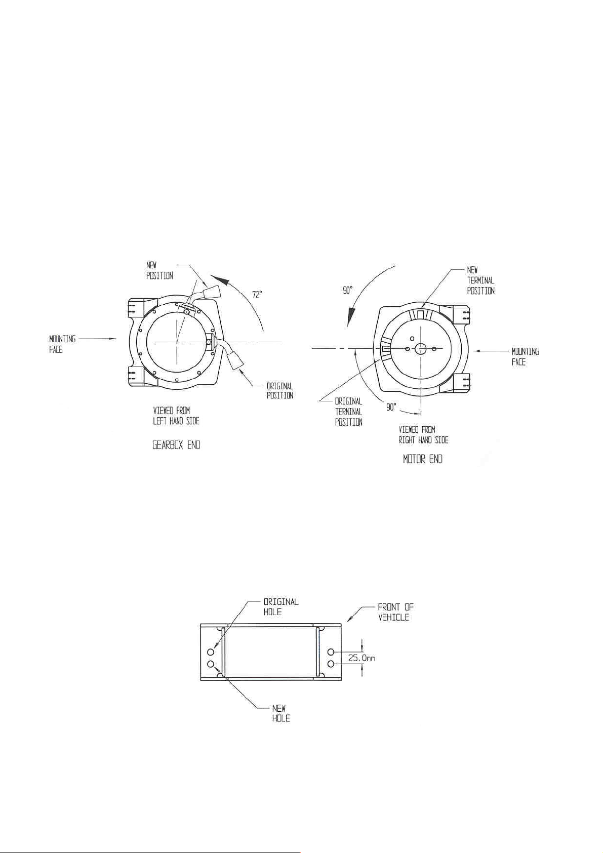
2. To place the winch clutch handle in a convenient location the winch gearbox must be rotated 2 hole spacings,
72 degrees, in an anti-clockwise direction when viewed from the gearbox end. Place the winch on its end and
remove all gearbox bolts. Gently raise the gearbox just enough to rotate it. Do not completely remove the
gearbox and avoid damaging the gasket. Refit all bolts and tighten. (Refer to diagram 1.) NOTE: The winch
handle is positioned at the top of the bull bar.
DIAGRAM 1 DIAGRAM 2
3. To place the winch motor in the correct location the winch motor must be rotated 90 degrees, in a clockwise
direction when viewed from the motor end. Place the winch on its end and remove the two motor retaining
bolts. Gently raise the motor just enough to rotate it. Do not completely remove the motor and avoid damaging
the gasket. Refit all bolts and tighten. (Refer to diagram 2.)
4. The roller fairlead must have new holes drilled to allow for correct wire rope angle. Using a 12mm diameter
drill bit, redrill the roller fairlead as shown. (Refer to diagram 3.)
DIAGRAM 3
Page 3

25/05/04 Page 3 of 4 3782582
5. Fit the control box bracket to the bull bar using two M6 x 16mm bolts, flat washers and flange nuts.
6. Fit the control box to the control box bracket using the two 1/4” nuts, flat washers and spring washers (supplied
in Warn kit). Centralise the control box in the cut-out then tighten nuts firmly.
NOTE: The gearbox is situated on the left hand side of the bull bar (as viewed from inside the vehicle). The cable
spools from the bottom.
7. Fit the winch and roller fairlead into the bull bar using bolts from the winch kit and four M10 washers from the
ARB bolt kit.
8. Connect the winch control box cables to the winch motor. Refer to the Warn handbook for additional
information. Connect the long winch + & - cables to the vehicle after the bull bar is installed. Refer to the
Warn winch manual for vehicle wiring instructions.
9. NOTE: Ensure that these cables are installed well clear of sharp, hot or moving objects. Secure the winch
cables to the bull bar with the cable ties supplied.
FITTING THE BULL BAR TO THE VEHICLE
10. Assemble the two buffers on to the bull bar using the eight M6 flange nuts supplied.
11. Remove bumper bar from the vehicle. (Refer to diagram 4 for removal details.)
DIAGRAM 4
12. Remove the indicators and number plate from the bumper bar.
13. Fit the number plate to the bull bar using the two M6 x 16mm bolts, flat washers and flange nuts.
14. Remove the chassis extensions from both sides of the front of the chassis. Retain the four bolts and discard
both extensions. (Refer to diagram 5.)
Page 4

25/05/04 Page 4 of 4 3782582
DIAGRAM 5 DIAGRAM 6
15. Secure the impact absorber to the front of the chassis using the original chassis extension M10 bolts. Fit the
two 7/16” X 4” bolts through the lower hole in the bracket and finger tighten all the bolts. (Refer to diagram 6.)
16. Lift the bar onto the impact absorber brackets and fasten using the eight M10 x 25mm bolts, flat and spring
washers.
17. Align the bull bar to the vehicle and tighten the bolts retaining the impact absorbs to the chassis to the specified
torque. Drill an 8mm hole in the chassis using the hole in the impact absorber as a guide. Fit the two M8 x
20mm bolts, flat washers and flange nuts and tighten to the specified torque.
18. Fit the indicators into the cut out in the bull bar and connect the indicator looms to the existing indicator loom.
NOTE: Fitting the indicators will be accessed from underneath the bar. Test to ensure the indicators function
correctly.
19. Bolt the air deflector to the underside of the bull bar with the air intake opening facing forward using four M8 x
20mm bolts, flat washers and flange nuts.
TORQUE SETTINGS:
M8 BOLTS
8.6 NM
M10 BOLTS
44 NM
 Loading...