

Page 1
21/05/07
Page 1 of 8
3783040
If you have any queries regarding the installation of this product please contact the distributor from whom it was purchased, or alternatively the ARB office in your state.
Head Office – ARB Corporation Ltd VIC: 42-44 Garden Street, Kilsyth, Victoria, 3137 Tel: (03) 9761 6622 Fax: (03) 9761 6807
WA:(08) 9244 3553 NSW: (02) 9821 3633 ACT: (02) 6280 7475 SA: (08) 8244 5001 QLD: (07) 3872 3872 NT: (08) 8947 2262 TAS: (03) 6331 4190
ARB WINCH / NON WINCH BULL BAR TO SUIT
LANDROVER DISCOVERY 2003 ONWARD .
FITTING KIT No’s :- 617 1793 BULL BAR WINCH ( P/No 343 2120 )
617 1794 BULL BAR NON WINCH ( P/No 323 2120 )
WARNING
FOR VEHICLES EQUIPPED WITH SRS AIRBAG
WHEN INSTALLED IN ACCORDANCE WITH THESE INSTRUCTIONS, THE FRONT
PROTECTION BAR DOES NOT AFFECT OPERATION OF THE SRS AIRBAG.
TAKE NOTE OF THE FOLLOWING:
• THIS PRODUCT MUST BE INSTALLED EXACTLY AS PER THESE INSTRUCTIONS USING
ONLY THE HARDWARE SUPPLIED.
• DO NOT USE THIS PRODUCT FOR ANY VEHICLE MAKE OR MODEL, OTHER THAN THOSE
SPECIFIED BY ARB.
• DO NOT REMOVE LABELS FROM THIS BULL BAR.
THIS PRODUCT OR ITS FIXING MUST NOT BE MODIFIED IN ANY WAY.
Page 2

21/05/07
Page 2 of 8
3783040
USE
PART No
QTY
DESCRIPTION
375 6482 LH
1
IMPACT ABSORBER LH
375 6482 RH
1
IMPACT ABSORBER RH
IMPACT ABSORBER
615 1243
6
M10 x 130 mm BOLT
TO CHASSIS
458 1048
6
M10 SPRING WASHER
458 1040
12
M10 FLAT WASHER
615 1026
6
M10 NUT
615 1081
2
7/16” x 4 ½” BOLT
458 1042
2
7/16” SPRING WASHER
458 1041
4
7/16” FLAT WASHER
615 1124
2
7/16” NUT
615 1045
8
M10 x 25 mm BOLT
IMPACT ABSORBER
458 1048
8
M10 SPRING WASHER
TO BULL BAR
458 1040
8
M10 FLAT WASHER
375 6499
1
CONTROL BOX BRACKET
CONTROL BOX BRACKET
615 1021
2
M8 x 20 mm B0LT
TO BULL BAR
458 1044
2
M8 FLAT WASHER
615 1132
2
M8 FLANGE NUT
375 1313
1
NUMBER PLATE BRACKET
NUMBER PLATE TO
615 1017
4
M6 x 16 mm BOLT
WINCH BAR
615 1046
4
M6 FLAT WASHER
615 1128
4
M6 FLANGE NUT
615 1017
2
M6 x 16 mm BOLT
NUMBER PLATE TO
615 1046
2
M6 FLAT WASHER
NON WINCH BAR
615 1128
2
M6 FLANGE NUT
615 1180
4
M6 x 20 mm BOLT
PLASTIC GUARD TRIM
615 1046
4
M6 FLAT WASHER
TO BULL BAR WING
615 1128
4
M6 FLANGE NUT
615 1045
2
M10 x 25 mm BOLT
LOCKING BOLT
458 1048
2
M10 SPRING WASHER
HARDWARE
458 1040
4
M10 FLAT WASHER
615 1026
2
M10 NUT
6821151L&R
1
ARB INDICATOR KIT
MISC
180 302
8
BLACK CABLE TIES
615 1017
4
M6 x 16 mm BOLT ( FOG LAMP TO BAR )
615 1046
4
M6 FLAT WASHER ( FOG LAMP TO BAR )
615 1277
6
SCREW COVER ( FOG LAMP )
615 1308
10
SCREW SELF TAPING ( TURN & FOG )
682 1116
4
NYLON PLUG ( TURN SIGNAL BRACKET )
EG50
1
GROMMET
584 8283
2
NYLON WASHER ( FOG LAMP SPACER )
682 1152
2
WIRING LOOM ( TURN SIGNAL )
615 1309
6
CAPTIVE NUT “U” TYPE - CLIP
615 1315
4
CAGE NUT M6
375 6563 L
1
BRACKET FOG LAMP LH
375 6563 R
1
BRACKET FOG LAMP RH
Page 3
21/05/07
Page 3 of 8
3783040
TOOLS REQUIRED: -
METRIC SPANNER & SOCKET SET , 7/16 SPANNER & SOCKET , ELECTRIC DRILL , DRILL BITS ,
10 mm x 180 mm EXTRA LONG DRILL BIT, SHARPE KNIFE AND A METRIC TAPE MEASURE .
ASSEMBLY SEQUENCE FOR ARB BULL BAR.
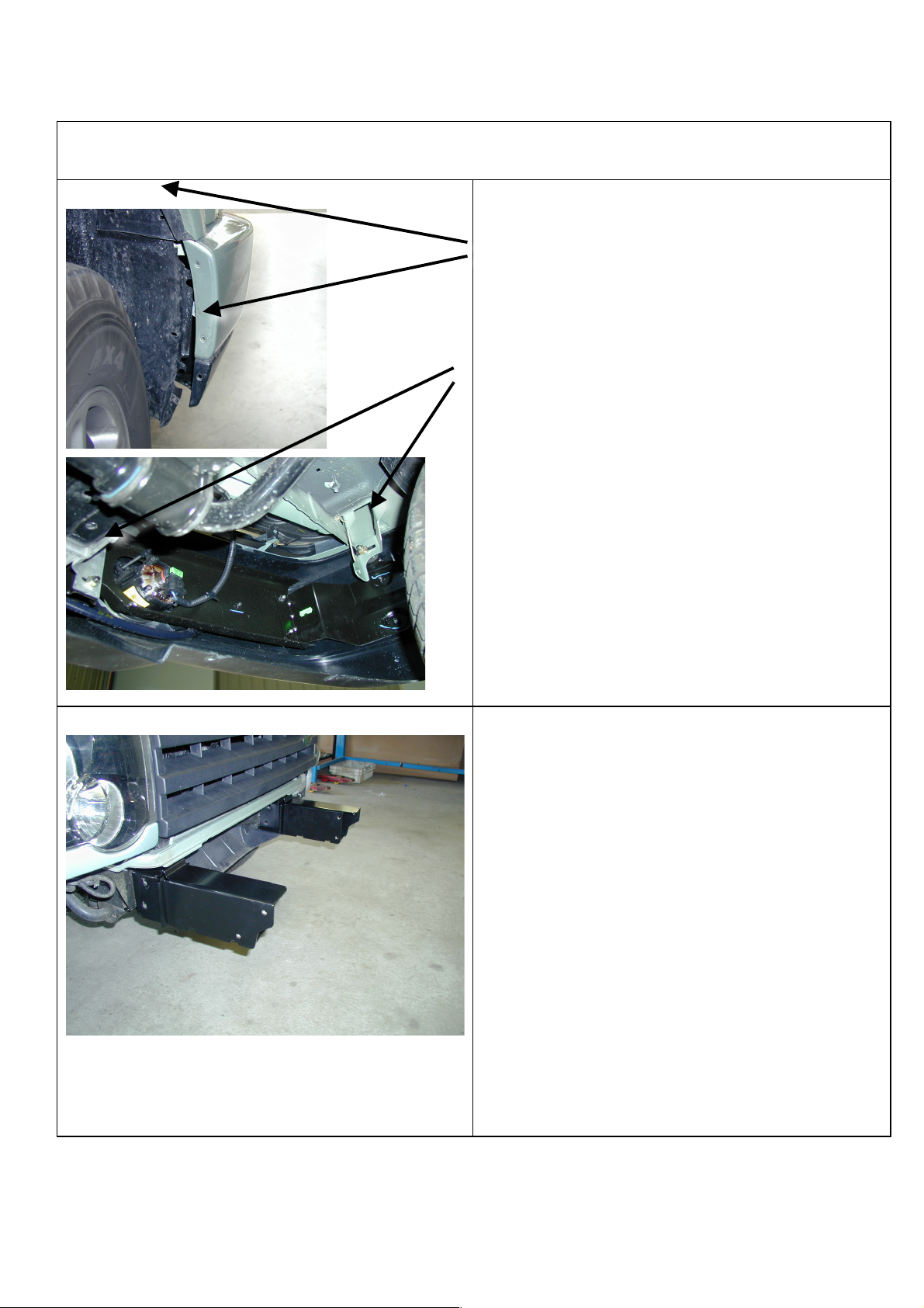
1.& 2.
1. To remove the bumper bar from the vehicle undo the
7 screws that hold the plastic guard liner to the
bumper bar on each side.
Undo the four nuts that hold the bumper to the
aluminum brackets and loosen the two nuts located on
the inside out board face .
Disconnect the fog lamp harness from both lamps and
with assistance pull the bumper bar forward enough to
disconnect the head lamp washers .
2. Remove the aluminum chassis extension brackets
from both sides . Remove the tubular cross brace
and the recovery bracket , both are refitted at a later
stage.
Undo the 5 screws that hold the plastic air shield in
place and with a small flat blade screw driver
remove the two yellow plugs from the under side of
the chassis rails .
3.&4.
3. Fit the new impact absorbers to both the LH & RH
chassis rails . Note the profiled edge faces outward
Using the 7/16 hardware supplied , bolt the RH
impact absorber into position .
At this stage only the two horizontal bolts are fitted ,
repeat this on the LH side using the M10 hardware
supplied ( bolts are longer on LHS to fit recovery
bracket ) .
4. Once the impact absorbers are sitting horizontal and
at the same height tighten both bolts . One of the
holes in the impact absorber bottom bracket should
line up with a square hole in the chassis .
Before drilling the vertical pinning bolts measure
the distance between the two out side edges of the
impact absorber – making sure the measurement is
no larger than 809 mm ( loosen bolts and adjust if
necessary ).
Page 4

21/05/07
Page 4 of 8
3783040
5.& 6 .
5. When drilling the vertical pinning bolt THE DRILL
MUST BE VERTICAL IN BOTH DIRECTIONS
failure to do so will result in damage to the radiator
mounting system .
Drill out both holes and assemble using the long M10
bolts and hardware supplied .
From the out board side of the chassis insert the
chassis packers between the under side of the chassis
and the impact absorber with the finger tab facing
downward .
Repeat this on the LHS .
6.
The plastic air shield needs to be trimmed before being
replaced , cut the holes ( located on the edge tabs )
into an open ended slot .
Place the shield back into its original position and
screw across the back edge in 3 locations .
The edge tabs are now pushed in on top of the packer ,
the tabs are retained when the vertical bolts are done
up and sandwiched between the chassis and
the chassis spacer .
Re – confirm the measurement between the impact
absorbers to ensure the bull bar will fit onto the
vehicle and tighten all of the vertical bolts .
7.
7. Remove the horizontal bolts only , as previously
described in step 3.
Re – assemble but this time the tubular cross brace
and the original recovery point are attached .
Note the recovery bracket is located to the left
hand chassis rail, and uses the longer metric
M10 bolts .
Page 5

21/05/07
Page 5 of 8
3783040
8.
8. Placing the original bumper bar face down on a
blanket remove all of the screws that hold the painted
outer section to the main bumper .Using pliers remove
the clip that holds the washer nozzle in the bumper
and take out the nozzle ( both sides ) .These are refitted into the bull bar once the fog lamp and turn
signal are installed .
Using a small flat bladed screw driver dis-engage the
locking tabs on both sides and remove the cover , this
will enable the fog lamp to be un-screwed in three
places and removed .
9.
Fit the “u” nuts to the fog lamp bracket , the nylon
washer fits between the bracket and the lamp
mounting foot ( located on the adjustment side ) fit
the fog lamp with the screws provided . Fit the screw
covers over the exposed end of the screws in 3 places
to each bracket.
Fit the M6 cage nuts into the large square holes in the
edge flange of the fog lamp bracket . From the inside
of the bracket , Squeeze the two legs of the cage nut
together and fit to the hole . NOTE :- The body of
the nut is closest to the fog lamp .
The Right hand fog lamp is shown .
Insert the nylon plugs into the square holes in the turn
signal aperture , located on the inside face of the bull
bar . From the rear , screw the turn signal assembly to
the bracket on the bull bar , with the clear portion of
the lens to the outboard edge .
Re-fit the washer nozzle both sides once the fog lamp
& turn signal are fitted . The washer retaining clip may
need to be flattened slightly to fit .
10.
10 When fitting a winch only :- Fit the control box
bracket to the bull bar using the M8 x 20 mm bolts
and hardware , with the open end of the bracket
facing the grill . Leave these bolts finger tight at this
stage .
Fit the grommet to the hole in the top of the bull bar
and feed the control box cables through
the grommet .
Page 6

21/05/07
Page 6 of 8
3783040
11.
11 WINCH BAR ONLY The roller fair lead must be
drilled prior to fitment , it can then be assembled into
the front of the bull bar along with the winch as
detailed in step 14 .
Using a 13.0 mm drill bit drill two holes as shown
in diagram 11.
The roller fair lead can then be fitted into the
bull bar.
12.
12 To place the winch clutch handle in an accessible
location, the gearbox must be rotated 2 bolt spaces
( 144 degrees ) in an anti-clockwise direction when
viewed from the gear box end .
Place the winch on its end and remove the gear box
bolts .Gently raise the gear box just enough to rotate
it ( about 5mm ) , DO NOT COMPLETLEY
remove the gear box as this will damage the gasket .
Once in the new position refit all gear box bolts and
tighten .
13.
13 The winch motor must also be rotated 90 degrees
in a clockwise direction when viewed from the
motor end .
Place the winch on its end and remove the 2 bolts
holding the motor to the body .Gently raise the motor
just enough to rotate it .
Once in the new position re-fit the 2 bolts and tighten
Page 7

21/05/07
Page 7 of 8
3783040
14.
14 With the roller fair lead previously in position , lift
the winch into position and bolt into place using the
3/8” hardware supplied with the winch , bolt securely
in place .
NOTE :- the gear box is on the left hand side . The
winch cable spools from the bottom of the winch
drum .
Wire the winch as per the winch instructions . Using
the cable ties , tie the wiring back to the rear edge of
the bull bar using the holes in the flange . Ensure the
wiring is clear of the winch drum & cable etc and
does not rub on any hot or moving parts or sharp
edges . Failure to do so could result in damage to
the electrical system .
15.
15 Attached the number plate directly to the bull bar
front face using the M6 hardware supplied .
If the bull bar is fitted with a winch use the number
plate bracket supplied and fit to the bull bar
as shown .
16.
16 With assistance lift the bull bar into position and slide
it over the two impact absorbers . Once in position
bolt the bull bar in the 8 places using the M10 bolts
& hardware supplied , finger tight only at this stage .
Adjust the bull bar on the vehicle until a uniform gap
is achieved to the grill & headlamp and guards .Once
happy with the position of the bull bar tighten all of
the bolts .
The bull bar is then drilled and pined in its final
position using the M10 hardware supplied as shown
in the attached photo .
Page 8

21/05/07
Page 8 of 8
3783040
17.
17 Re-connect the fog lamp harness on both sides of the
vehicle .
The turn signal is supplied with a loom kit , this is
plugged in to the turn signal one end and spliced into
the vehicles original wiring at the other end .
Cable tie both the turn signal and fog lamp wiring
where appropriate .
Ensure the turn signal & fog lamps are working
correctly .
Reconnect the head lamp washer tubes on both sides.
18.
18 Trim the plastic inner guard liners by aligning with
the bull bar and using the hole in the wing as a
guide , drill a 6 mm hole and secure with the M6
hardware supplied .
 Loading...