

Page 1
ARB TACOMA COMBO BULL BAR 2005 ONWARDS.
• PART No 3423030
WARNING
FOR VEHICLES EQUIPPED WITH SRS AIRBAG
WHEN INSTALLED IN ACCORDANCE WITH THESE INSTRUCTIONS, THE FRONT
PROTECTION BAR DOES NOT AFFECT OPERATION OF THE SRS AIRBAG.
TAKE NOTE OF THE FOLLOWING:
• THIS PRODUCT MUST BE INSTALLED EXACTLY AS PER THESE INSTRUCTIONS
USING ONLY THE HARDWARE SUPPLIED.
• IN THE EVENT OF DAMAGE TO ANY BULL BAR COMPONENT, CONTACT YOUR
NEAREST AUTHORISED ARB STOCKIST. REPAIRS OR MODIFICATIONS TO THE
IMPACT ABSORPTION SYSTEM MUST NOT BE ATTEMPED.
• DO NOT USE THIS PRODUCT FOR ANY VEHICLE MAKE OR MODEL, OTHER THAN
THOSE SPECIFIED BY ARB.
• DO NOT REMOVE LABELS FROM THIS BULL BAR.
• THIS PRODUCT OR ITS FIXING MUST NOT BE MODIFIED IN ANY WAY.
Tools Required For Bar Fitment: Basic Tool Kit, ½” socket set , Cir-Clip pliers, Drill, 10mm bit
and ¼” socket set
05-09-05 Page 1 of 15 3783174
If you have any queries regarding the installation of this product please contact the distributor from whom it was purchased, or alternatively the ARB office in your state.
WA:(08) 9244 3553 NSW: (02) 9821 3633 ACT: (02) 6280 7475 SA: (08) 8244 5001 QLD: (07) 3872 3872 NT: (08) 8947 2262 TAS: (03) 6331 4190
Head Office – ARB Corporation Ltd VIC: 42-44 Garden Street, Kilsyth, Victoria, 3137 Tel: (03) 9761 6622 Fax: (03) 9761 6807
Page 2

USE. PART NO.
Chassis Mount Assembly
Bull Bar To Chassis Mount
Assembly
Stone Tray to Bull Bar
Buffers To Bull Bar
Indicators To Bull Bar
Licence Plate To Bull Bar
Miscellaneous
3756781
3756794L
3756794R
6151095
6151135
4516049
4581050
4581007
6151104
6151139
6151133
4581040
4581048
6151232
6151026
6151304
6151232
4581040
4581048
6151026
6542063
6151300
6151180
4581072
4581036
3162470R
3162470L
6151128
6821151R
6821151L
6821116
6151308
6821152
180701
6151128
6151046
6151180
3751313
EG50
180302
BLB850
6151074
QTY DESCRIPTION
1
1
1
4
4
6
6
6
2
2
2
10
6
4
4
6
10
14
10
4
1
8
8
8
8
1
1
12
1
1
4
4
2
6
4
4
4
1
2
10
3
4
Bracket Mount Assembly
Bracket Tension LHS
Bracket Tension RHS
Bolt M12 x 1.25 x 35mm
Nut M12 x 1.25
Washer Flat ½”
Washer Spring ½”
Washer Flat M12 x 4mm HD (Large )
Bolt ½”x 4”UNC
Nut ½’UNCNut M10 x 1.25
Nut M10 x 1.25
Washer Flat M10
Washer Spring M10
Bolt M10 x 1.5 x 30mm
Nut M10 x 1.5
Nut Cage M10 x 1.5
Bolt M10 x 1.5 x 30mm
Washer Flat M10 x 2mm
Washer Spring M10
Nut M10 x 1.5
Stone Tray
Nut Cage 6mm
Bolt M6 x 20mm
Washer Flat M6
Washer Spring M6
Buffer Standard RHS
Buffer Standard LHS
Nut Flange M6
Indicator Kit, RHS
Indicator Kit, LHS
Nylon Plug
Screw, Self Drilling
Wiring Loom
Scotch Lock
Nut Flange M6
Washer Flat M6
Bolt M6 x 20mm
Bracket Number Plate
Rubber Grommet 3/8” ID
Cable Ties
Cable Black 850mm
3/8” x 13/4” UNC Bolts
01-09-06 Page 2 of 15 3783174
Page 3
Bracket Control Box to
Bull Bar
3751564
6151021
4581044
6151132
1
2
2
2
Bracket control box mount
Bolt M8 x 20mm
Washer Flat M8
Nut Flange M8
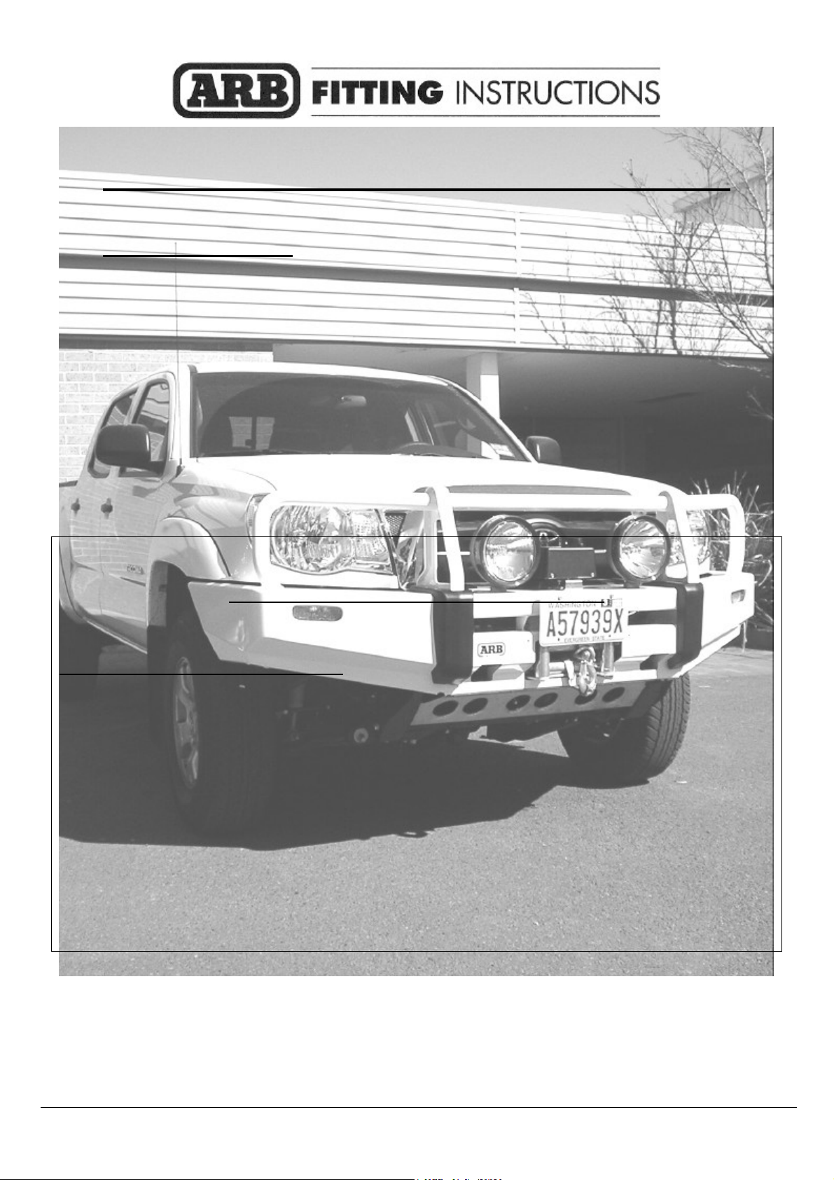
1. Remove front bumper cover from
vehicle.
2. Remove side bumper supports from
both guards.
3. It is recommended that you paint satin
black under guard line.
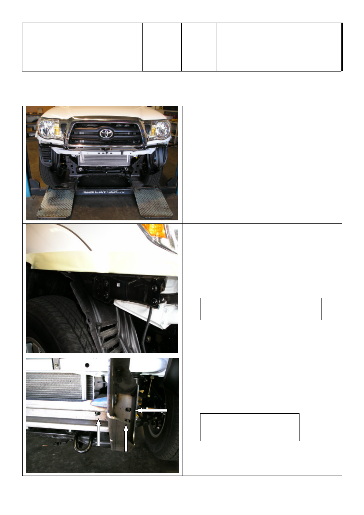
Photo is of RHS of vehicle.
4. Fit bracket mounting assembly to front
of vehicle using the 6 x 10mm studs to
locate on.
ARROWS INDICATE STUDS
ON LHS OF VEHICLE
01-09-06 Page 3 of 15 3783174
Page 4
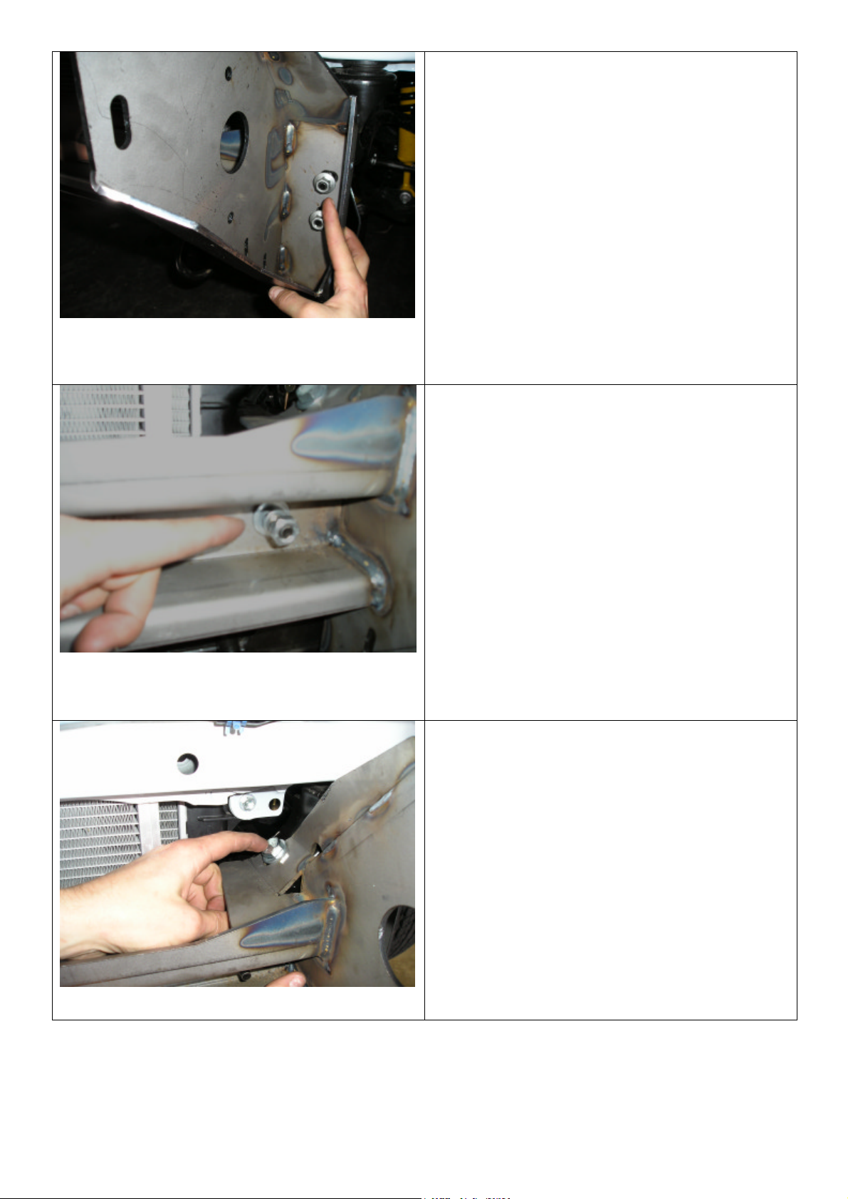
5. Fit original 10mm nuts to the outside
fixing points . See Photo:
6. Fit 10mm x 1.25mm nuts ( fine thread)
spring washers and flat washers ( from
bull bar bolt kit ) to both the centre
studs. See Photo:
7. Fit 12 x 35mm x 1.25 (fine thread)
bolt,12mm flat washer through top
rearward bracket passing through body
mount.
See Photo:
01-09-06 Page 4 of 15 3783174
Page 5
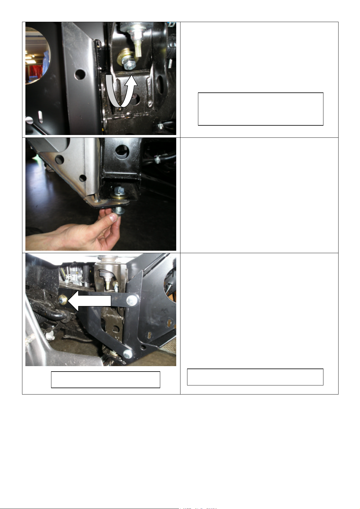
8. Secure from underneath using large
12mm gold coloured flat washer,12mm
spring washer and 12mm nut to both
sides of vehicle.
See Photo:
PHOTO VIEWED FROM UNDER
LHS OF VEHICLE
9. Secure lower fixing point by passing
through lower bracket in a upward
motion, using M12 bolt, 12mm flat
washer and secure from the top using
large gold coloured 12mm flat
washer,12mm spring washer and
12mm nut ( fine thread ) to each side of
vehicle. When all bolts are fitted,
tighten securely.
PHOTO IS OF RHS OF VEHICLE
10 Lastly fit tension brackets to each side
of vehicle. The two front fixing bolts are
M10 x 30mm,flat washers, spring washers
and M10 nuts. The rear bolt is 4” x ½’
which is passed through the chassis from
outside of vehicle and fitted with a large
gold 12mm washer and a ½’Nyloc nut on
the inside of vehicle. When all bolts are
fitted, tighten front 10mm bolts securely
and tighten rear ½” bolt to a torque setting
of 30ft lb ( NO MORE )
ARROW INDICATES THE ½” BOLT
01-09-06 Page 5 of 15 3783174
Page 6

11. If vehicle is fitted with fog lights,
remove globes from sockets and cable tie
fog light loom to vehicle panel.
ie There is no provision for
fog lights in the bull bar
PHOTO IS LHS OF VEHICLE
12. Cable tie under guard plastic
moulding up to vehicle front pan.
13. Fit M10 caged nuts to the inside of
mounting surface of bull bar.
( 3 to each side of bull bar. )
PHOTO IS OF INSIDE LHS OF BULL BAR.
01-09-06 Page 6 of 15 3783174
Page 7

14….Fit white nylon plugs into square holes.
PHOTO IS OF INSIDE LHS OF BULL BAR.
15. Align indicator/parker light above
white nylon plugs and secure to bull bar
using self tapping screws.
16 .Fit M6 caged nuts to inside lower flange
of inside of bar.
17..Fit two to each side.
THESE CAGED NUTS ARE TO BOLT ON
SPLASH PAN.
01-09-06 Page 7 of 15 3783174
Page 8

n 8/9/9.5/000lb winch, rotate
18. Fit buffers to bar and secure from inside
of bull bar using 6mm flange nuts. Six to
each side of vehicle.
DO NOT OVER TIGHTEN
ORIGINAL
VIEWED FROM
LHS OF VEHICLE
ROTATED
TO FIT A WINCH BAR
19 . To fit a
gearbox 72° counterclockwise.
Stand winch upright and undo the capped
head screws and by lifting the gearbox only
a couple of millimetres, rotate the gearbox.
Once in position, refit all screws and
tighten firmly.
WARNING: Do not lift gearbox more
than a couple of millimeters.
01-09-06 Page 8 of 15 3783174
20. Remove the cover from the control box.
21. Replace the three main power cables that
go from winch to control box. Make sure that
you identify the colour codes on the new
cables before closing control box cover.
This must be done for whatever winch is to
be fitted to the bull bar.
Page 9

22. Bolt control box bracket to top of bar
using 8mm hardware.
23. Fit rubber grommet to RHS of bar.
24. Drill two new 13mm holes in the roller
fairlead provided in the kit, as shown on
the adjacent picture.
25. Place the winch on a table with the feet
facing up and using an assistant;
carefully lift the bull bar on top of the
winch.
26. Attach the winch to the bull bar using
two 1 ½” x 3/8” bolts from the winch
fitting kit, 3/8” spring washer and 3/8”
flat washers in the top holes.
01-09-06 Page 9 of 15 3783174
Page 10

.
27. Position the roller fairlead, and remove
the circlips from the lower of the verticle
rollers and push the pins up to give access
to the lower bolts.
28. Fix the roller fairlead to the bar using the
1 ¾” x 3/8” bolts, spring and flat washers.
29. When all bolts are fitted and tighten, refit
vertical roller pins back into roller fairlead
and refit circlips.
30. Fit number plate bracket to bar using
6mm hardware.
01-09-06 Page 10 of 15 3783174
Page 11

GROUND WIRE
31. Fit control box to control box bracket and
pass cables through rubber grommet.
32. Fit all 3 cables to their correct terminals
and tighten. Refer to Warn installation
instruction when wiring up winch. Fit
plastic boots over terminals. Cable tie
cables to brace as per photo to clear of
all moving parts. Fit ground wire under
winch tie rod. ( See Photo )
33. With the help of a friend, lift bull bar on
to chassis mount bracket and align holes
with 10mm caged nuts already fitted. ( 3
each side )
34. Secure using M10 x 30mm bolt,M10
spring washer and M10 flat washer.
01-09-06 Page 11 of 15 3783174
ARROWS INDICATE WHICH HOLES
TO USE IN SECTION VIEW DRAWING
SECTION VIEW IS LHS OF VEHICLE.
Page 12

6MM CAGED NUTS
35. Align bull bar so there is a 15mm to
20mm gap around periphery under front
vehicle panels, then tighten all bolts
securely.
36. Finally, using the existing 2 holes as a
template. Drill through using a M10 drill
bit and secure using the balance of the
10mm hardware.
(These bolts are to lock the bull bar to the
chassis mounting bracket )
37. Fit M6 caged nuts to the inside of the
flanges on the splash pan.
01-09-06 Page 12 of 15 3783174
Page 13

ARROWS INDICATE M6 BOLT POSITION
38. Fit splash pan to lower flange of bull bar
using M6 x 20mm bolts,6mm spring
washers and 6mm large flat washers.
Finger tighten only.
39 . Fit splash pan to bull bar sides using
M6 x 20mm bolts,6mm spring washers and
6mm large flat washers. Finger tighten only.
40. When all bolts are fitted tighten
securely
41. Fit number plate to number plate
bracket using M6 hardware.
42. Driving lights can be fitted at this stage
and can be tighten using a ratchet and
socket which fits through the gap as per
arrow
01-09-06 Page 13 of 15 3783174
Page 14

43. There is two positions for the number
plate to be fitted to the bull bar.
44. Top arrow is position to bolt number
plate for a winch bar.
45. Lower arrow is position to bolt number
plate for a non winch bar.
FUNCTION INDICATOR
INDICATOR GREEN GREEN /
EARTH BLACK WHITE/BLACK WHITE/BLACK
PARK LAMP RED GREEN GREEN
HARNESS
VEHICLE COMBINATION LAMP
RIGHT LEFT
GREEN / BLACK
YELLOW
46. There is a provision on both sides
of bar for a HiLift to be used.
47. Finally fit indicator/parker light
loom extension to light and wire to
vehicle main light loom using scotch
locks as per table.
01-09-06 Page 14 of 15 3783174
Page 15

01-09-06 Page 15 of 15 3783174
 Loading...