

Page 1

TOYOTA TACOMA (USA)
PRODUCT NUMBER 3423020
WARNING
FOR VEHICLES EQUIPPED WITH SRS AIRBAG
WHEN INSTALLED IN ACCORDANCE WITH THESE INSTRUCTIONS, THE FRONT
PROTECTION BAR DOES NOT AFFECT OPERATION OF THE SRS AIRBAG.
TAKE NOTE OF THE FOLLOWING:
• THIS PRODUCT MUST BE INSTALLED EXACTLY AS PER THESE INSTRUCTIONS
USING ONLY THE HARDWARE SUPPLIED.
• DO NOT USE THIS PRODUCT FOR ANY VEHICLE MAKE OR MODEL, OTHER THAN
THOSE SPECIFIED BY ARB.
• DO NOT REMOVE LABELS FROM THIS BULL BAR.
• THIS PRODUCT OR ITS FIXING MUST NOT BE MODIFIED IN ANY WAY.
30-11-04 Page 1 of 8 3782653
Page 2

FITTING KIT NUMBER 6171370
USE PART No QTY DESCRIPTION
6151096
6151095
IMPACT ABSORBERS 4581050
TO CHASSIS RAILS 4581049
6151138
6151105
3751872L
3751872R
SPLASH PAN 6151021
TO BULL BAR 4581044
3314401
6151132
BULL BAR TO 6151045
IMPACT ABSORBERS 4581048
4581040
BUFFERS TO BULL BAR 6151132
6151021
CONTROL BOX BRACKET 4581044
3751564
6151132
NUMBER PLATE BRACKET 6151017
6151046
6151128
3751542
BUFFERS AND INDICATORS 3500200
3500080
8-9000lb WINCH TO PAN 4581040
180302
THE FOLLOWING PARTS ARE ONLY FOR 2002 MODEL ONWARD
BOLT M12 x 40mm
2
BOLT M12 x 1.25 PITCH X 35mm
2
WASHER SPRING M12
6
WASHER FLAT M12
8
NUT ½” UNC
2
BOLT ½” x 4 ½” UNC
2
IMPACT ABSORBERS
1
IMPACT ABSORBERS
1
BOLT M8 x 20mm
3
WASHER FLAT M8
3
SPLASH PAN
1
NUT FLANGE
3
BOLT M10 x 25mm
6
WASHER SPRING M10
6
WASHER FLAT M10
6
NUT FLANGE M8
4
BOLT M8 x 20mm
2
WASHER FLAT M8
2
CONTROL BOX BRACKET
1
NUT FLANGE M8
2
BOLT M6 x 16mm
4
WASHER FLAT M6
4
NUT FLANGE M6
4
NUMBER PLATE BRACKET
1
BUFFERS KIT
1
ARB INDICATORS
1
WASHER FLAT 3/8”x 1”
4
CABLE TIES
6
CHASSIS EXTENSION 3756405
6151246
4581049
4581050
3756407
5846400
6151294
6151021
4581044
4581046
BRACET CHASSIS EXTENSION
2
BOLT M12 X 1.75 PITCH X 25MM
2
WASHER M12
2
WASHER SPRING M12
2
BRACKET SUMP GUARD SUPPORT ASSY
1
PACKER RECTANGULAR
2
“U” NUT M8
3
BOLT M8 X 20MM
3
WASHER M8
3
WASHER SPRING M8
3
TOOLS REQUIRED
1 BASIC TOOL KIT, DRILL, ½” DRILL BIT. ¾” LONG REACH SOCKET. (IF DRIVING LIGHTS ARE TO BE FITTED)
30 11 04 Page 2 of 8 3782653
Page 3
ASSEMBLY SEQUENCE FOR BULL BAR INSTALLATION.
1. Remove bumper bar, tie down rings, and tow
hook from the vehicle.
2. Remove the crush cans from the front of the
vehicle. (On 2002 models onward, the crush cans
are welded to the sump guard support cross
member which must be removed)
3. Fit the indicators into bar.
4. Fit number plate bracket to bull bar using 6mm
hardware.
5. Fit control box bracket to bull bar using 8mm
hardware.
6. Fit buffers to bull bar using M8 flange nuts
supplied in buffer kit.
NOTE: DO NOT OVER TIGHTEN.
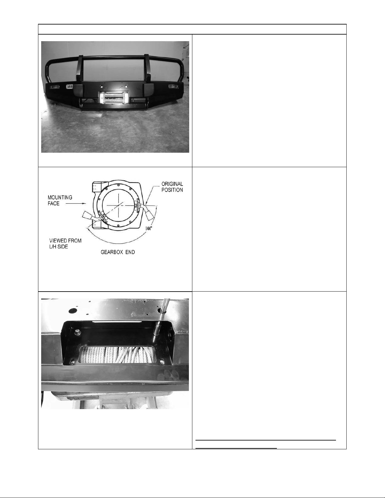
7. To place the clutch handle in the correct
position, the winch gearbox must be rotated 144
degrees (4 hole spacings), in anti- clockwise
direction when viewed from gearbox end. Place the
winch on its end and remove all gearbox bolts.
Gently raise the gearbox just enough to rotate it.
When the correct position is located, refit all bolts
and tighten.
NOTE: Take care not to lift the assembly more
than a couple of millimetres while rotating to
correct position to avoid unmeshing the gears.
See diagram opposite.
8. Once winch is rotated, positioned winch on
bench face up.
9. Lower bull bar on top of winch and align holes
with each other. Using 1 1/4” x 3/8” bolts and flat
washers from bolt kit, secure the two most upper
holes first and finger tighten. Remove top circlips
from vertical rollers of fairlead and remove pins
and rollers, this is done so there is easy access to
lower bolts.
10. Place roller fairlead in bar cutout over lower
holes and fasten using 1 1/2” x 3/8” bolts and 3/8”
flat washers supplied in bolt kit.
11.When all is positioned, tighten all bolts firmly
and replace rollers, pins and circlips back to roller
fairlead.
If fitting the XP 9.5 winch, continue to step 12,
otherwise, jump to step 19.
30 11 04 Page 3 of 8 3782653
Page 4

12.
If fitting the XP 9.5 winch, remove the cover from
the control box.
13. Remove the two cap screws, nuts and spacer
washers that hold the four solenoids in place.
14. Remove the four solenoids from the base of the
control box using the copper bus bar as an aid and
hold to one side.
30 11 04 Page 4 of 8 3782653
Page 5

15. Remove the two bolts in the base of the control
box and reposition them into the more centralised
holes
Before
After
16. Place the 4 solenoids over the 2 metal stands
that are facing upwards. Make sure they line up
with the holes in the base.
17. Replace the 2 cap screws, washers and nuts
removed in step 13 above into original holes.
18. Replace the black cover and refit the three
cover screws (DO NOT OVER TIGHTEN)
30 11 04 Page 5 of 8 3782653
Page 6

19. Fit control box to control box bracket and
tighten firmly.
20. Pull wires through viewer cutout under control
box and wire up as per Warn instruction manual.
21. Tie back cables clear of all moving parts with
cable tie supplied.
22. Place ground earth lead under bolt of winch
tension bar.
FOR 2002 MODELS ONWARD go to step 23.
FOR PREVIOUS MODELS go to step 24. (The parts listed in step 23 will not be required)
23. Push the 3 M8 “U” nuts onto the sump guard
support and bolt the chassis extension and support
to the front of the chassis using 2 M12 x 35mm
fine pitch bolts, flat washers, spring washers and
rectangular packer.
24. Fit impact absorbers to both sides of the
vehicle.
25. On LHSide of vehicle, refit tow hook using
original 12mm bolts.
26.
Prior 2002 models
, fit 12mm x 30mm fine
pitch bolt to the front of the chassis.
2002 models
on, fit 12mm x 25mm course pitch
bolts to the front of the chassis extension.
27. From underneath of bracket, drill right through,
using ½” drill bit and fit 4 ½” bolt upward with
washers and nut.
28.On RHSide of vehicle under impact absorber,
relace tie downs and bolt up using 12mm x 40mm
bolts etc.
29. When all bolts are fitted, finger tighten only.
30 11 04 Page 6 of 8 3782653
Page 7

30. Lift bar into position between impact absorbers
and bolt up using M10 x 25mm bolts, spring and
flat washers. Finger tighten only. (Bolts fit from
inside of bar.)
31. At this stage, firmly tighten all impact absorber
bolts.
32. Adjust bar so that there is a 20mm gap around
the periphery of the vehicle and securely tighten all
remaining bolts throughout.
33. Wire main power leads to battery as per Warn
instructions and cable tie leads securely from all
moving parts with cable ties supplied.
34.Fit number plate to bar using 6mm hardware.
35.Pull winch cable through roller fairlead, and fit
tow hook.
36. Connect the indicator looms to the existing
indicator loom with the Scotchloks supplied. Test
to ensure the indicators function correctly.
37.
Prior 2002 models
. Once bar is correctly fitted,
undo front bolts in splash pan of vehicle, slide bar
plate in between and refit bolts and finger tighten.
2002 models on
, splash pan is bolted to bull bar as
above and bolted to cross member installed in step
23. using 8mm hardware supplied.
38. Using 8mm hardware supplied, bolt plate to
front of underside of bar. When all bolts are fitted,
tighten firmly.
39. If driving lights are to be fitted, use extension
bar with ratchet, ¾” long reach socket to tighten
from cutout in centre pan.
30 11 04 Page 7 of 8 3782653
Page 8

40. Winch handle is operated from this cutout.
30 11 04 Page 8 of 8 3782653
 Loading...