

Page 1
03/12/04 Page 1 of 11 3782893
If you have any queries regarding the installation of this product please contact the distributor from whom it was purchased, or alternatively the ARB office in your state.
Head Office – ARB Corporation Ltd VIC: 42-44 Garden Street, Kilsyth, Victoria, 3137 Tel: (03) 9761 6622 Fax: (03) 9761 6807
WA: (08) 9244 3553 NSW: (02) 9821 3633 ACT: (02) 6280 7475 SA: (08) 8244 5001 QLD: (07) 3872 3872 NT: (08) 8947 2262 TAS: (03) 6331 4190
ARB WINCH/NONWINCH BULLBAR
TO SUIT HJ100 IFS
PRODUCT No. 3413050 (Pre 09/2002)
WARNING
FOR VEHICLES EQUIPPED WITH SRS AIRBAG
WHEN INSTALLED IN ACCORDANCE WITH THESE INSTRUCTIONS, THE
FRONT
PROTECTION BAR DOES NOT AFFECT OPERATION OF THE SRS AIRBAG.
TAKE NOTE OF THE FOLLOWING:
• THIS PRODUCT MUST BE INSTALLED EXACTLY AS PER THESE
INSTRUCTIONS USING ONLY THE HARDWARE SUPPLIED.
• IN THE EVENT OF DAMAGE TO ANY BULL BAR COMPONENT,
CONTACT YOUR NEAREST AUTHORISED ARB STOCKIST. REPAIRS OR
MODIFICATIONS TO THE IMPACT ABSORPTION SYSTEM MUST NOT
BE ATTEMPED.
• DO NOT USE THIS PRODUCT FOR ANY VEHICLE MAKE OR MODEL,
OTHER THAN THOSE SPECIFIED BY ARB.
• DO NOT REMOVE LABELS FROM THIS BULL BAR.
• THIS PRODUCT OR ITS FIXING MUST NOT BE MODIFIED IN ANY WAY.
IMPORTANT
• This bull bar is suitable for Warn 9000lb, 9500lb High Speed,
10000lb, and 12000lb winches. Note: if fitting a 10000lb or 12000lb
winch cable kit 6171397 is required.
Tools Required
10mm, 14mm, 18mm, 19mm, 22mm Spanners and Sockets. Phillips head screwdriver, hacksaw, drill
& 10mm drill bit.
Optional Extras suited for this bar includes a range of IPF driving lights and
durable driving light covers. Contact your nearest ARB stockest for further
information.
Page 2

03/12/04 Page 2 of 11 3782893
FITTING KIT No: - 6171406(Pre 09/2002) 6171752 (09/2002On)
USE
PART No
QTY
DESCRIPTION
MOUNT ASSY TO VEHICLE
6151257
2
BOLT M12 X 200mm
4581049
6
WASHER FLAT
4721469
2
TUBE PACKER
5846282
2
CHANNEL PACKER
4581050
2
WASHER SPRING M12
6151189
2
NUT M12
6151258
2
BOLT M14 X 80mm
4581052
4
WASHER SPRING M14
5846283
4
PACKER 10mm THICK
3756202
1
MOUNT ASSY.
BULLBAR TO MOUNT ASSY
6151255
6
BOLT M12 X 40mm
4581050
6
WASHER SPRING M12
4581007
6
WASHER FLAT M12 LARGE
6151045
2
BOLT M10 X 25mm
4581039
4
WASHER M10 FLAT
4581048
2
WASHER M10 SPRING
6151026
2
NUT M10
WINCH
4581040
4
WASHER 3/8”
CONTROL BOX FITTMENT
3756220
1
CONTROL BOX BRACKET
6151017
2
BOLT M6 X 16MM
6151128
2
NUT FLANGE M6
6151046
2
WASHER M6
ROLLER FAIRLEAD FITTMENT
6151255
2
BOLT M12 X 40mm
4581050
2
WASHER SPRING M12
4581049
4
WASHER FLAT M12
6151189
2
NUT M12
WINCH COVER FITTMENT
6151128
2
NUT FLANGE M6
6151256
2
SCREW M6 S/STEEL BUTTON HEAD
6191001
1
WINCH COVER EXTRUSION
6521036
1
WINCH COVER (Pre 09/2002)
6522018
1
WINCH COVER (09/2002 On)
6151046
2
WASHER M6
BUFFERS
3500170
1
BUFFER KIT WITH 8 M6 NUTS
NUMBER PLATE FITTMENT
6151017
4
BOLT M6 X 16mm
6151128
4
NUT FLANGE M6
3756234
1
BRACKET NUMBER PLATE
6151046
2
WASHER M6
WIRING
3500080
1
INDICATOR KIT
180302
6
CABLE TIE
Page 3
03/12/04 Page 3 of 11 3782893
ASSEMBLY SEQUENCE FOR BULLBAR.
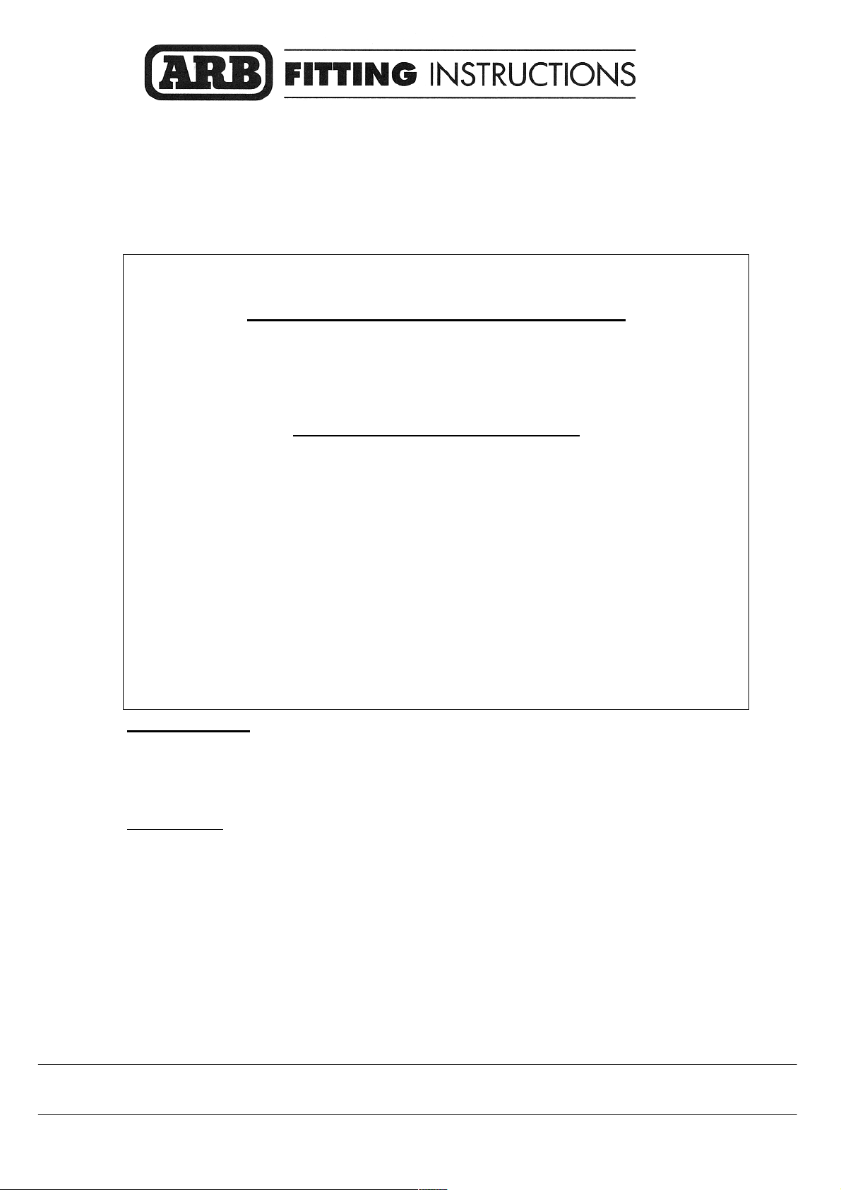
1. 1. Remove the bumper bar and grill.
2. Remove the cross member and tow brackets. See
picture.
3. Bend the sheet metal returns located under the light
area down so they don’t interfere when the bar is
fitted. Mask under the light trim and guard and paint
flat black.
4. Bend the center bracket back approx 90 degrees.
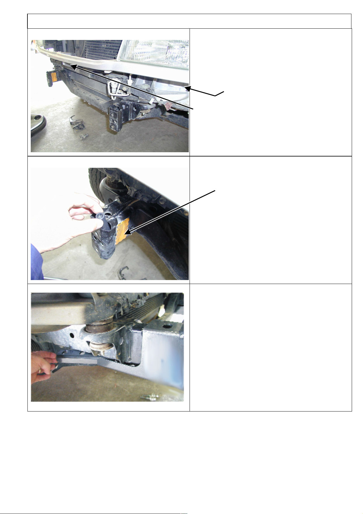
2. 1. Insert the tube packers, one in each chassis arm. Line
the bottom of the tube to the bottom hole of the
chassis rail. Rest the top of the tube to the front of the
chassis rail. The tube should be angled forward.
3. 1. Slide the mount assy. over the chassis rails. Try not
to shake the vehicle too severely as the tube packers
may fall out of place.
2. Insert the channel packers from the rear. Make sure
the hole correspond to the holes in the mount.
3. Push the entire mount as far back as possible.
Page 4
03/12/04 Page 4 of 11 3782893
ASSEMBLY SEQUENCE FOR BULLBAR.
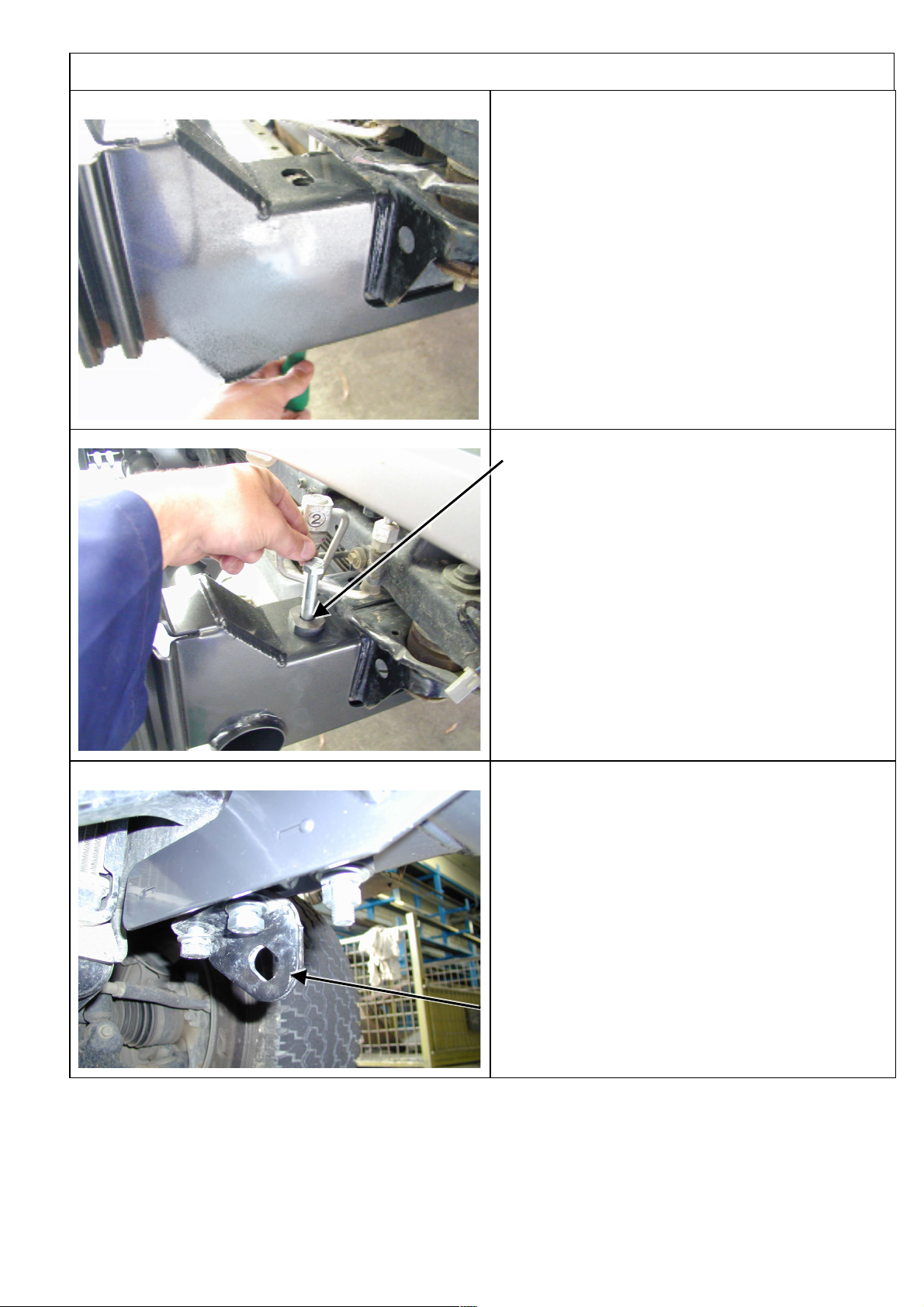
4. 1. Using a long screwdriver insert it through the
bottom hole so it passes through the tube packer.
This may require a visual check from under the
vehicle to see the position of the tube.
2. Using the screwdriver twist around until the packer
is inline with the top hole.
5. 1. Insert the M12 X 200mm bolt through the top hole
using one of the 10mm thick packers. Push through
while removing the screwdriver from underneath
until the bolt locates right through.
Note: For turbo diesel models remove the intercooler
hose to gain access for the M12 X 200mm bolt.
6. 1. Fasten the remainder of the mount using:
2 M14 bolts removed earlier from tow bracket
2 M14 bolts from fitting kit
6 M14 flat washers
4 M14 spring washers
2 10mm thick packers
2 M12 nuts
2 M12 spring washers
Note: Assemble with the tow brackets.
Page 5

03/12/04 Page 5 of 11 3782893
ASSEMBLY SEQUENCE FOR BULLBAR.
7.
1. For pre 09-2002 models use vice grips, multi grips
or pliers bend back the bumper mounting arm
approximately 90 degree’s to clear winch bumper
when assembled.
8. 1. On models built after 09-2002 if you are fitting a
10000lb or 12000lb winch you will need to remove
the upright support and cut a section of it out.
9. 1. Once removed hold the upright in a vice and cut out
the section shown with a hacksaw.
2. Replace the upright and continue fitting the winch.
Page 6

03/12/04 Page 6 of 11 3782893
ASSEMBLY SEQUENCE FOR BULLBAR.
8.
Viewed from passenger side, gearbox end.
9000lb & H/S 9500lb
Viewed from passenger side, motor end.
10000lb & 12000lb
(If fitting with winch)
To place the clutch handle in a convenient location the
winch gearbox must be rotated.
1. Place the winch on its end and remove all gearbox
bolts.
2. Gently raise the motor just enough to rotate it.
3. Do not completely remove the motor and avoid
damaging the gasket.
4. Refit and tighten all bolts.
Note: Take care not to lift the assembly more than a
couple of millimeters while rotating to the desired
position to avoid unmeshing the gears.
9.
(If fitting with winch.)
1. Place the winch on the mount assembly.
2. Bolt from underneath using bolts supplied with
winch and the 3/8” washers supplied in the fitting kit.
Refer to Warn installation instructions for correct
procedure.
Note: If fitting 9000lb or 9500lb high speed winches
mount on the front hole positions. If fitting 10000lb or
12000lb winches mount on the rear hole position.
Fasten the two front bolts first then push the winch to
the back position. Fasten the two rear bolts then tighten
all bolts. Move front lower tie rod to rear lower position
for 10000lb and 12000lb winches.
Page 7

03/12/04 Page 7 of 11 3782893
ASSEMBLY SEQUENCE FOR BULLBAR.
10. (If fitting with winch)
1. Bolt the roller fair lead to the winch bumper using
the M12 X 40mm bolts, washers, spring washers
and nuts.
11. 1. Fasten the indicator lights to the bar.
2. Position the bar on the mounts and fasten the bar to
the mounts using the M12 X 40mm bolts, large washers
and spring washers.
3. Line up the end of the wing to the wheel arch and
leave approximately a 15mm gap between the bar and
the vehicle. Tighten all bolts.
Note: The lower bolt can be accessed through the cutout
at the front of the wing.
12. (If not fitting winch)
1. Wrap rubber extrusion around winch cover.
2. Place washers over the winch cover fixing holes
located on the top middle face of the winch bumper.
3. Place the winch cover on top of the winch bumper
inline with the mount holes.
4. Bolt together using the M6 button head stainless
steel screws and M6 nuts.
Page 8

03/12/04 Page 8 of 11 3782893
ASSEMBLY SEQUENCE FOR BULLBAR.
13.
1. Next step is to lock pin the bar so there is no
movement by drilling a 10mm hole on both sides of
vehicle, fasten with 10mm x 25mm bolts plus 10mm
hardware.
14.
(If fitting with winch)
1. Feed the winch cable through the roller fair lead.
Mount the hook to the end of the cable.
15.
Fitting with winch
Fitting without winch
(If fitting with winch.)
1. Bolt the number plate to the number plate bracket
using the M6 bolts and M6 flange nuts.
2. Bolt the assembly to the bar as shown in the
illustration using the M6 bolts and M6 flange nuts.
(If not fitting with winch.)
1. Bolt the number plate through the top holes using
M6 X 16mm bolts and M6 flange nuts.
Page 9

03/12/04 Page 9 of 11 3782893
ASSEMBLY SEQUENCE FOR BULLBAR.
16. 1. If fitting the XP 9.5 winch, remove the cover from
the control box.
For any other winch, go to step 22.
17. 1. Remove the two cap screws, nuts and spacer washers
that hold the four solenoids in place.
18. 1. Remove the four solenoids from the base of the
control box using the copper bus bar as an aid and hold
to one side.
Page 10

03/12/04 Page 10 of 11 3782893
ASSEMBLY SEQUENCE FOR BULLBAR.
19.
Before
1. Remove the two bolts in the base of the control box
and reposition them into the more centralised holes
After
20. 1. Place the 4 solenoids over the 2 metal stands that are
facing upwards. Make sure they line up with the holes in
the base.
21. 1. Replace the 2 cap screws, washers and nuts removed
in step 17 above into original holes.
2. Replace the black cover and refit the three cover
screws (DO NOT OVER TIGHTEN)
Page 11

03/12/04 Page 11 of 11 3782893
ASSEMBLY SEQUENCE FOR BULLBAR.
22.
(If fitting with winch)
1. Assemble the control box bracket to the control box
using M6 nuts located on the control box bolts.
2. Mount the control box to the bar using M6 X 16
bolts and M6 flange nuts. Fasten the control box to
the front of the cutout on the top pan. This should
leave an opening at the rear for viewing the cable
drum while operating the winch.
Note: If fitting a 10000lb or 12000lb winch cable kit
6171397 is required. Replace the control box cables with
the new longer cables.
23. 1. Fasten the buffers using the M6 flange nuts
supplied.
24.
(If fitting with winch)
Connect the winch control box cables to the winch motor. Refer to the Warn handbook for additional
information. Connect the long winch + & - cables to the vehicle after the bar is installed. Refer to the Warn
winch manual for vehicle wiring instructions. Note: if fitting a 10000lb or 12000lb winch cable kit 6171397 is
required. Use the longer leads to replace ones on control box.
Ensure that these cables are installed well clear of sharp, hot or moving objects. Secure the winch cables
to the vehicle and winch bumper with the supplied cable ties.
25.
Wire the turn signal lights to the vehicle wiring.
 Loading...