

Page 1

SXV 450 – 550
Van Den Bosch Replica
Page 2

SUMMARY TABLE WITH TECHNICAL DATA
FRONT FORK
Type Marzocchi Shiver 50
Travel 267mm
Std. adjustment hydraulic brake under compression 20 clicks from all closed
Std. adjustment hydraulic brake under extension 20 clicks from all closed
Steering angle with centred bushings 25°
Steering angle with eccentric bushings 24° - 26°
Fork offset with centred bushings 14mm
Fork offset with eccentric bushings 11mm - 17mm
REAR SHOCK ABSORBER
Type Mono Sachs racing
Travel 120mm
Std. spring elasticity (K) 5.8 kgf/mm
Std. adjustment hydraulic brake under compression at high speed 10 clicks from all closed
Std. adjustment hydraulic brake under compression at low speed 15 clicks from all closed
Std. adjustment hydraulic brake under extension 20 clicks from all closed
STM CLUTCH
Calibration of primary standard spring SXV VDB 450 (wet race) 120 kg
Calibration of primary supplied spring SXV VDB 450 130 kg
Calibration of secondary standard spring SXV VDB 450 (wet race) 30 kg
Calibration of secondary supplied spring SXV VDB 450 40 kg
Calibration of primary standard spring SXV VDB 550 (wet race) 130 kg
Calibration of primary supplied spring SXV VDB 550 140 kg
Calibration of secondary standard spring SXV VDB 550 (wet race) 30 kg
Calibration of secondary supplied spring SXV VDB 550 40 kg
Wear limit clutch pack 35.00mm
PINION/SPROCKET
Standard pinion SXV VDB 450 z=13
Supplied pinion SXV VDB 450 z=14
Standard sprocket SXV VDB 450 z=45
Supplied sprocket SXV VDB 450 z=44, z=46
Standard pinion SXV VDB 550 z=15
Supplied pinion SXV VDB 550 z=14
Standard sprocket SXV VDB 550 z=46
Supplied sprocket SXV VDB 550 z=45, z=47
Page 3
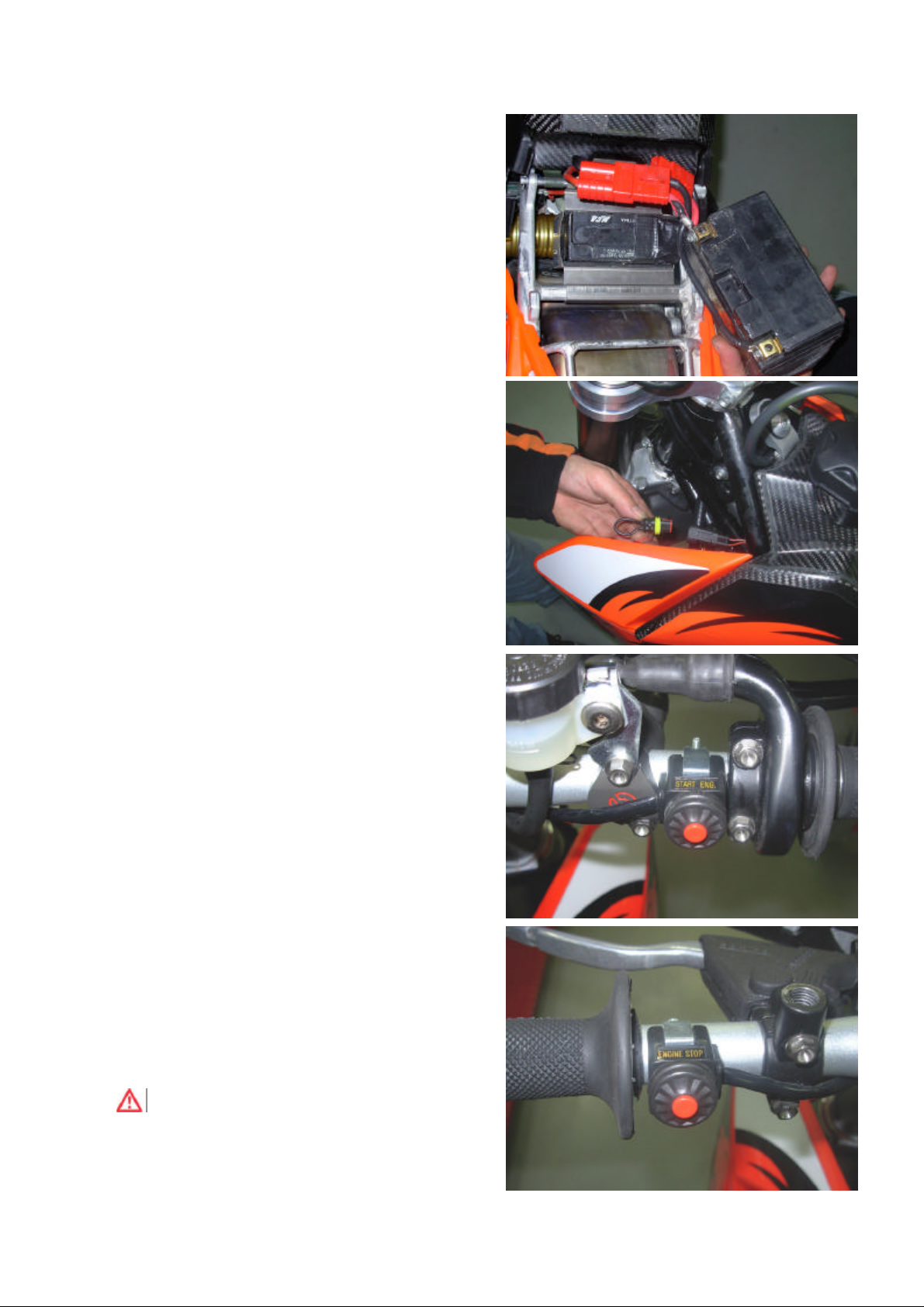
STARTING THE VEHICLE
This vehicle, having been designed for exclusive use in
competitions, is equipped with a small and lightweight
battery, sufficient for amperages needed during warm startups and for the normal operation of the engine.
For cold start it is necessary to use the external battery that
comes with as an accessory to the vehicle.
• Remove the saddle.
• Disconnect the jack from the regular battery and connect
it to the external battery.
• Feed the injection circuit of the vehicle by connecting the
key jack on the handlebar.
• Start the engine using the ignition button on the right
side of the handlebar.
• With the engine running, disconnect the external battery
and reconnect the installed battery.
• To turn off the vehicle just press the off button on the left
side of the handlebar.
WARNING
After use the key jack has to be disconnected.
Page 4
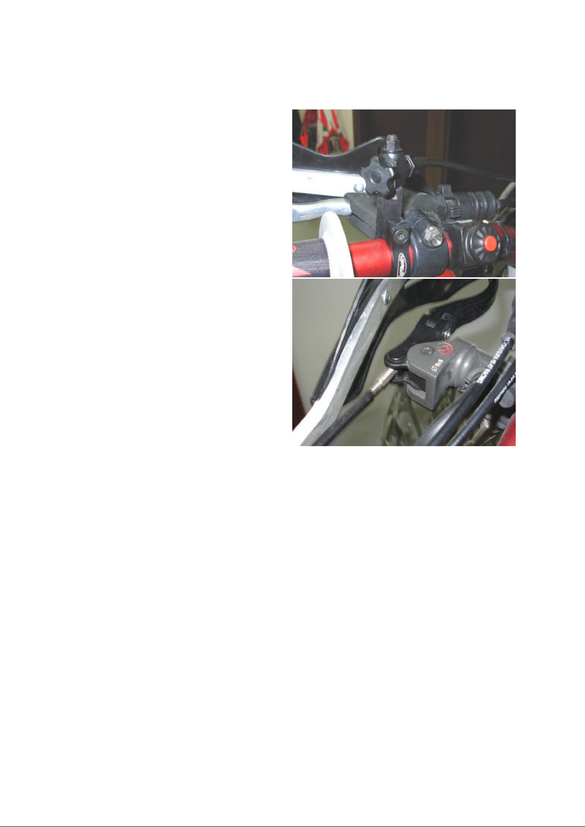
REMOTE ADJUSTMENT OF THE POSITION OF THE FRONT BRAKE
LEVER
• The vehicle is prearranged for a remote adjustment of
the distance of the front brake lever from the handlebar.
• Use the adjustment knob on the left handlebar until the
desired distance is obtained.
Page 5
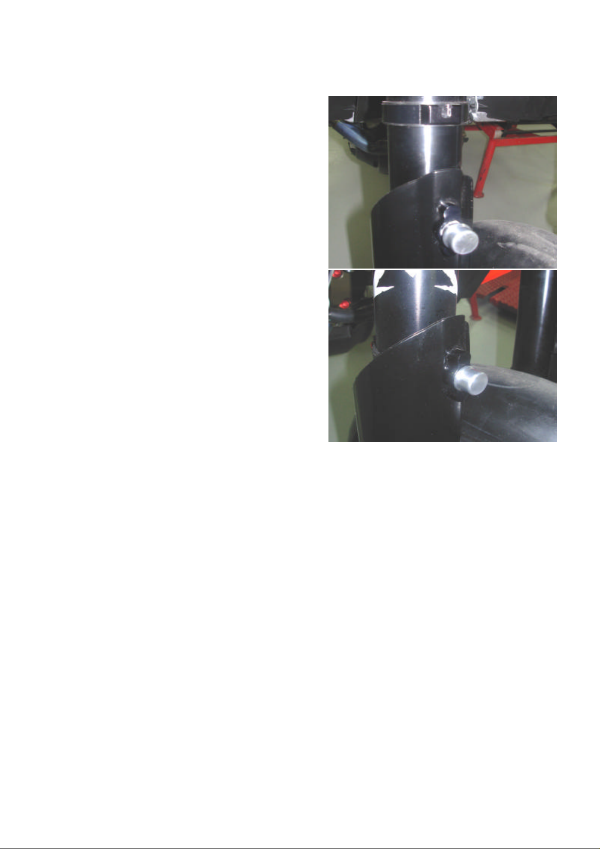
STARTING DEVICE
• The vehicle is set up for locking the fork under
compression as a launch control.
• Press the fork all the way.
• Press on the locking pin.
• Release the fork so that the pin engages on the slot of
the ring mounted on the fork.
• Release the pin.
Page 6

ASYMMETRIC CHAIN TENSIONER PADS
DIRECTION
OF TRAVEL
DIRECTION
OF TRAVEL
• The vehicle is provided with two different chain
sprockets.
• It is possible to replace the chain sprocket and to rotate
the chain tensioner pads without having to adjust the
slack of the chain again.
• Mount the chain tensioner pads in the direction indicated
when installing the sprocket with more teeth.
• Mount the chain tensioner pads in the direction indicated
when installing the sprocket with less teeth.
WARNING
Changing the direction of the chain tensioner
pads corresponds to 1 tooth of the sprocket.
Page 7

FRONT FORK
ADJUSTMENT OF THE HYDRAULIC BRAKE
• In order to adjust the hydraulic brake under compression
operate on the screw shown to the side.
• In order to adjust the hydraulic brake in extension
operate on the screw shown to the side.
DE-AERATION OF THE FRONT FORK
• To extract the air from the clutch stem, remove the dust
cap on each one of the fork legs.
• With the help of a screwdriver open the bleed valve until
the air inside is completely expelled.
Page 8

ADJUSTMENT OF THE STEERING ANGLE
WARNING
To adjust the steering angle the eccentric
bushings must be first assembled.
• Loosen the headstock nut.
• Loosen the screw that closes the upper plate.
• By operating on both fork legs, loosen the tightening
screws on the upper plate.
• Slightly lift the upper plate, by pulling it out by a few
millimetres from the fork legs.
Page 9

• Using a hook spanner, loosen the bearings preload ring
nut.
• The ring nut to work on is the upper one, immediately
below the steering plate.
WARNING
At this stage do not work on the ring nut for
adjusting the steering angle, located
immediately under the bearings preload ring
gear.
• Loosen the screw that locks the lower eccentric ring nut.
• Loosen the screw that locks the upper eccentric ring nut.
Page 10

• Using a hook spanner, turn the upper eccentric ring nut
by 180°.
WARNING
Accurately line up the notch on the ring nut with
the point where the tubes of the frame meet
(vehicle axis).
• Restore the vehicle following, in reverse, the procedure
just described.
FORK OFFSET ADJUSTMENT
• Loosen the headstock nut.
• Loosen the screw that closes the upper plate.
• Loosen the screw that closes the lower plate.
Page 11

• Operating on the square drive nut, turn the headstock
strut by 180°.
• Minimum offset reference.
WARNING
Precisely line up the notch on the eccentric
bushing with the reference on the steering plate.
• Maximum offset reference.
WARNING
Precisely line up the notch on the eccentric
bushing with the reference on the steering plate.
Page 12

REAR MONO-ABSORBER
ADJUSTMENT OF THE HYDRAULIC BRAKE
• In order to adjust the hydraulic brake under compression
turn the gold screw inside the blue knob.
• To adjust the threshold of intervention of the bypass
valve (hydraulic brake in high speed compression)
operate on the blue knob.
• In order to adjust the hydraulic brake in extension
operate on the screw shown to the side.
SPRING PRELOAD ADJUSTMENT (NEGATIVE)
• Loosen the locking screw of the spring pre-load
adjustment ring.
• Using the adjustment pin provided, act on the ring nut
until the desired spring preload is obtained.
• At the end of the operation, tighten the locking screw.
Page 13

B
ADJUSTMENT OF THE VEHICLE HEIGHT
• The height of the vehicle can be adjusted on 3 different
positions.
• The adjustment is obtained by replacing or by turning
the position of the bushing shown in the picture.
• Two are the available bushings:
A: Bushing for medium height
B: Eccentric bushing for max. or min. height (depending
on the direction of the assembly)
A
Page 14

ANTIHUPPING CLUTCH
DISASSEMBLY OF THE CLUTCH FROM THE
ENGINE
• Remove the six screws that secure the ergal flange.
• Remove the ergal flange.
• Lock the clutch with the lock wrench (provided) and
remove the nut.
• Pull out the clutch unit from the main shaft of the gear
box and continue the disassembly on the bench.
• Remove the central cup.
Page 15

• Remove the thrust ring.
• Remove the outside spring.
• Remove the clutch pressure plate and the complete
pack of disks.
• Remove the inside spring.
Page 16

• Remove the ring.
• Remove the disc drum
• Remove the six steel balls.
WARNING
The steel balls have to be greased before
reassembly.
• The two springs can be replaced with springs with a
different elastic constant K to adapt the response of the
clutch to its requirements.
 Loading...