

Page 1

MainStage 3
User Guide
For OS X
Page 2

K Apple Inc.
Copyright © 2013 Apple Inc. All rights reserved.
Your rights to the software are governed by the accompanying
software license agreement. The owner or authorized user of
a valid copy of the MainStage software may reproduce this
publication for the purpose of learning to use such software.
No part of this publication may be reproduced or transmitted
for commercial purposes, such as selling copies of this
publication or for providing paid for support services.
The Apple logo is a trademark of Apple Inc., registered in
the U.S. and other countries. Use of the “keyboard” Apple
logo (Shift-Option-K) for commercial purposes without the
prior written consent of Apple may constitute trademark
infringement and unfair competition in violation of federal and
state laws.
Every eort has been made to ensure that the information in
this manual is accurate. Apple is not responsible for printing or
clerical errors.
Because Apple frequently releases new versions and updates
to its system software, applications, and Internet sites, images
shown in this manual may be slightly dierent from what you
see on your screen.
Apple
1 Innite Loop
Cupertino, CA 95014–2084
408-996-1010
www.apple.com
Apple, the Apple logo, AppleScript, Finder, FireWire,
GarageBand, Jam Pack, Logic, Logic Pro, Mac, MainStage,
Spotlight, Time Machine, and Ultrabeat are trademarks of
Apple Inc., registered in the U.S. and other countries.
IOS is a trademark or registered trademark of Cisco in the U.S.
and other countries and is used under license.
Other company and product names mentioned herein
are trademarks of their respective companies. Mention of
third-party products is for informational purposes only and
constitutes neither an endorsement nor a recommendation.
Apple assumes no responsibility with regard to the
performance or use of these products.
019-2555
Page 3

Contents
9 Chapter 1: Introducing MainStage
9 What is MainStage?
10 MainStage for keyboard controllers
10 MainStage for electric guitars
10 MainStage for vocals, drums, and other instruments
11 How to use MainStage in your music setup
12 MainStage in live performance
13 Chapter 2: Set up your system
13 Setup overview
14 Connect MIDI devices
14 MIDI devices overview
15 Connect a USB music keyboard
15 Connect MIDI keyboards and modules
17 Multichannel MIDI devices
17 Turn o internally generated sounds
18 Connect audio devices
18 Audio devices overview
18 Connect a microphone
19 Connect an electric instrument
20 Connect an audio interface
21 Speakers and other audio devices
21 Eects plug-ins and MainStage
22 Chapter 3: The MainStage interface
22 The MainStage window
23 Layout mode
24 Edit mode
25 Perform mode
26 Resize the workspace
27 Chapter 4: Get started with MainStage
27 Before you start
27 Choose a template
29 Select patch settings in the Patch Library
30 Add a patch
31 Select and play patches
31 Add a channel strip
33 Change a channel strip setting
34 Learn a controller assignment
34 Map a screen control
36 Try out Perform mode
36 Use Quick Help
3
Page 4

37 Chapter 5: Work in Edit mode
37 Edit mode overview
38 Work with patches in Edit mode
38 Select items in the Patch List
39 Copy, paste, and delete patches
39 Reorder and move patches in the Patch List
40 Create a patch from several patches
40 Set the time signature for patches
40 Change the tempo when you select a patch
41 Set program change and bank numbers
42 Defer patch changes
42 Instantly silence the previous patch
42 Change patch icons
43 Change the tuning for a patch
45 Work with channel strips in Edit mode
45 Channel strips overview
46 Show signal ow channel strips
47 Show the metronome channel strip
47 Create an alias of a channel strip
48 Add a patch bus
48 Channel Strip Inspector
49 Choose channel strip settings
50 Rename channel strips
50 Change channel strip colors
51 Change channel strip icons
51 Use feedback protection with channel strips
52 Work with software instrument channel strips
55 Use the EXS24 mkII Instrument Editor in MainStage
56 Use multiple instrument outputs
57 Use external MIDI instruments in MainStage
58 Delete channel strips
59 Create keyboard layers and splits
59 Layers and splits overview
59 Dene the key range
61 Set oating split points
61 Set the velocity range
62 Work with graphs
64 Create controller transforms
65 Work with plug-ins in Edit mode
65 Work with plug-ins overview
65 Add and remove plug-ins
65 Move and copy plug-ins
66 Use Channel EQ
66 Use plug-in settings
67 Adjust plug-in parameters
68 Use other plug-in window controls
Contents 4
Page 5

69 Map screen controls
69 Screen controls overview
69 Map screen controls to channel strip and plug-in parameters
71 Map screen controls to actions
73 Map a screen control to multiple parameters
74 Edit the saved value for a mapped parameter
74 Set drum pads or buttons to use note velocity
75 Use parameter mapping graphs
75 Map screen controls to all channel strips in a patch
75 Undo screen control parameter mappings
75 Remove screen control mappings
76 Work in the Assignments and Mappings tab
76 Assignments and mappings overview
77 Create and delete assignments and mappings
78 Edit assignments and mappings
78 Edit Hardware Input parameters
78 Block incoming controller messages
79 Edit screen control parameters in Edit mode
79 Screen control parameters in Edit mode overview
79 Replace parameter labels
79 Choose custom colors for screen controls
79 Change the appearance of a background or grouped screen control
80 Set screen controls to show the hardware value
80 Set parameter change behavior for screen controls
81 Set hardware matching behavior for screen controls
81 Reset and compare changes to a patch
82 Override concert- and set-level mappings
83 Work with sets in Edit mode
83 Work with sets overview
83 Create sets
83 Rename sets
83 Set the time signature for sets
84 Change the tempo when you select a set
84 Change the tuning for sets
84 Collapse sets in the Patch List
84 Override concert-level key ranges for a set
85 Delete sets
85 Add a channel strip at the set level
86 Share patches and sets between concerts
86 Record the audio output of a concert
Contents 5
Page 6

87 Chapter 6: Work with concerts
87 Open and close concerts
88 Save concerts
89 How saving aects parameter values
90 Set the time signature for a concert
90 Use tempo in a MainStage concert
90 Tempo overview
91 Tap the tempo
91 Get the tempo from MIDI Input
92 Dene the source for program change messages
92 Set the pan law for a concert
92 Change the tuning for a concert
92 Silence MIDI notes
93 Mute audio output
94 Work at the concert level
94 Concert level overview
95 Control the overall volume of a concert
96 Add concert-wide eects
97 Use auxes to control channel strip output
98 Add channel strips at the concert level
99 The MainStage clock
100 Control the metronome
101 Chapter 7: Work in Layout mode
101 Layout mode overview
102 Work with screen controls in Layout mode
102 Screen controls overview
103 Screen control types
104 Add screen controls to a layout
105 Copy and paste screen controls
106 Move screen controls
106 Resize screen controls
107 Align and distribute screen controls
108 Adjust the shelf for a shelf control
109 Group screen controls
110 Delete screen controls
111 Assign hardware controls to screen controls
111 Controller assignments overview
111 Knob assignments
112 Button assignments
113 Edit screen control parameters
113 Screen control parameter editing overview
113 Lift and stamp screen control parameters
114 Common screen control parameters
115 Keyboard screen control parameters
115 MIDI activity screen control parameters
116 Drum pad screen control parameters
116 Waveform screen control parameters
117 Selector screen control parameters
117 Text screen control parameters
117 Background screen control parameters
Contents 6
Page 7

118 How MainStage passes through MIDI messages
118 Export layouts
119 Import a layout
119 Change the aspect ratio of a layout
120 Chapter 8: Perform live with MainStage
120 Before the performance
120 Use Perform mode
121 Select patches in performance
121 Select patches in performance overview
121 Select patches using key commands
121 Select patches by typing
122 Select patches using actions
122 Select patches using program change messages
122 Screen controls in performance
122 Tempo changes in performance
123 Tips for performing with keyboard controllers
123 Tips for performing with guitars and other instruments
124 Tune guitars and other instruments with the Tuner
125 The Playback plug-in in performance
126 Record your performances
126 After the performance
126 Tips for complex hardware setups
127 Appendix A: The Playback plug-in
127 Playback plug-in overview
128 The Playback interface
129 Use the Playback waveform display
130 Playback transport and function buttons
131 Playback information display
132 Playback Sync, Snap To, and Play From parameters
133 Use the Playback group functions
134 Use the Playback Action menu and File eld
135 Use markers with the Playback plug-in
136 Use the Playback plug-in in a concert
136 Add a Playback plug-in
137 Add an audio le to the Playback plug-in
138 Set the Sync mode for the Playback plug-in
138 Choose the ex mode for the Playback plug-in
139 Add screen controls for the Playback plug-in
140 Tips for using the Playback plug-in
140 Assign Playback plug-ins to groups
Contents 7
Page 8

141 Appendix B: The Loopback plug-in
141 Loopback plug-in overview
142 The Loopback interface
143 Loopback waveform display
143 Loopback transport and function controls
144 Loopback information display
145 Loopback Sync, Snap To, and Play From parameters
145 Use the Loopback group functions
146 Loopback Action menu
147 Add a Loopback plug-in
148 Appendix C: MainStage preferences
148 Preferences overview
148 General preferences
149 Audio preferences
151 MIDI preferences
151 Display preferences
152 Appendix D: Key commands
152 Concerts and layouts
152 Patches and sets (Edit mode)
153 Editing
153 Actions
153 Parameter mapping (Edit mode)
154 Channel strips (Edit mode)
154 Screen controls (Layout mode)
154 Perform in Full Screen
155 Window and view
155 Help and support
156 Appendix E: MainStage actions
156 Actions overview
156 Table of actions
Contents 8
Page 9
Introducing MainStage
1
What is MainStage?
MainStage is a music application designed for use in live performance. MainStage turns your
computer into a powerful multi-instrument and eects processor that you can use on stage
when you perform. Whether you sing or play a keyboard, guitar, or another instrument, you can
use MainStage when you perform live.
•
Using a USB or MIDI keyboard controller, you can play a wide variety of software instruments,
including pianos and other keyboards, synthesizers, strings, horns, percussion, and more.
•
If you play electric guitar, you can play through virtual amps and use eects such as overdrive,
reverb, and compression.
•
Vocalists, drummers, and other musicians can sing and play with multi-eects setups using
a microphone.
In MainStage, you organize and access your sounds in concerts. A concert can store all the sounds
you’ll use in an entire performance or a series of performances. In a MainStage concert, individual
sounds are stored as patches, and each patch can contain one or more channel strips, each with
its own instruments and eects. You can add channel strips, choose channel strip settings, add
instruments and eects, and edit their parameters to customize your sounds. You can even mix
channel strips of dierent types in a single patch.
You organize patches for a concert in the Patch List, which includes grouping them into sets,
which are folders where you can store patches you want to keep together.
Each concert includes a visual interface, called a layout, with screen controls that you use to
modify your patches in live performance. Screen controls include keyboards, faders, knobs,
buttons, pedals, drum pads, and other hardware controls and displays. You make connections
between your MIDI devices and your MainStage concert by assigning hardware controls to
the screen controls in the concert, then map the screen controls to channel strip and plug-in
parameters, completing the connection so you can easily manipulate the parameters for each
patch in the concert.
Parameter
mapping
Channel strip or
plug-in parameter
Hardware control
Controller
assignment
MainStage screen control
9
Page 10

You can also map screen controls to actions, which provide the ability to select patches, control
the Tuner or metronome, provide visual feedback, and perform other functions.
MainStage lets you quickly and easily make controller assignments and parameter mappings
to speed your workow. You can customize your layout to match the controls on your MIDI
hardware, to optimize the use of available screen space, or in other ways that suit your needs.
MainStage for keyboard controllers
If you perform using a USB or MIDI keyboard controller, you can play and control MainStage
patches with software instruments using your controller. You can assign faders, knobs, buttons,
and other controls on the keyboard controller to screen controls in your concert, and then map
those screen controls to parameters in your patches. You can choose exactly the parameters
you want to have at your ngertips for each patch and access them from your controller as
you perform.
You can use MainStage with other MIDI controllers, including sustain pedals, expression pedals,
foot switches, MIDI guitars, and wind controllers that send standard MIDI messages. You can also
control external hardware synthesizers, ReWire applications, and other software instruments
using external instrument channel strips.
MainStage for electric guitars
If you play an electric guitar, you can use MainStage as a powerful, customizable multi-eects
processor. After you connect your instrument to your computer using an audio interface, you
send your guitar’s audio signal to audio channel strips in your patches, where you can add eects
including the Amp Designer and Pedalboard plug-ins designed specically for use with electric
guitar. You can also use EQ, compression, reverb, overdrive, and other eects in your guitar
patches. You can control volume, eect blend, or expression with an expression pedal, and use a
foot switch to select patches hands-free when you perform.
MainStage for vocals, drums, and other instruments
Vocalists and acoustic musicians can use MainStage by sending the audio output from a
microphone connected to their computer to audio channel strips in their patches. You can
use MainStage with Core Audio-compatible audio devices, such as audio interfaces and digital
mixers, for input from instruments and microphones, and for audio output to speakers, monitors,
a mixing board, or a public address (PA) system. In MainStage, you can access a wide range of
eects in your patches.
Drummers can also use MainStage by sending the audio output from microphones to audio
channel strips in their patches or by using drum pads or a virtual drum kit to control the
EXS24 mkII sampler, Ultrabeat, and percussion-oriented plug-ins.
Chapter 1 Introducing MainStage 10
Page 11

How to use MainStage in your music setup
You can add MainStage to your music equipment setup by following these steps:
Create a concert from a template
You start by creating a new concert from a template for keyboard, guitar, vocals, or another
instrument. MainStage recognizes many popular MIDI controllers and automatically assigns
hardware controls on the controller to corresponding screen controls in the workspace,
simplifying hardware setup. For more information, see Choose a template.
Add and edit patches to customize your sounds
You add patches for the sounds you want to play and edit the patches by adding channel strips,
instruments, and eects, and adjusting their parameters to “dial in” your custom sounds. In
Edit mode, you can select and play patches, choose channel strip settings, and edit channel strip
and plug-in parameters. You can quickly dene key ranges for channel strips to create keyboard
layers and splits, scale expression and other parameters using transforms, and lter incoming
MIDI messages. Your patches are “live” so you can hear the results of your edits instantly. For more
information, see Edit mode overview.
Organize patches for easy access
In Edit mode, you can order patches in the Patch List, organize patches in sets for added
exibility, and add channel strips at the set level, so they are available with every patch in the set.
For information about organizing patches, see Reorder and move patches in the Patch List. For
information about creating and editing sets, see Work with sets overview.
Customize the visual layout of your concert
In Layout mode, you arrange screen controls to create the visual layout for the concert.
Screen controls include keyboards, knobs, faders, and other hardware controls, as well as
controls to display parameter and system information, text and images, and a patch selector.
You can group controls and add grouped controls to your layout. For more information, see
Screen controls overview.
Make connections between MainStage and your music hardware
In Layout mode, you connect hardware controls on your MIDI devices to screen controls in
your layout by assigning the hardware controls to screen controls. You can move and resize
screen controls in the workspace, and customize the visual display of parameter values and
other information. You only need to make controller assignments once for an entire concert,
minimizing the amount of work required to connect your hardware with your computer. For
more information, see Controller assignments overview.
Map screen controls to the parameters you want to control
Edit mode is where you map screen controls to channel strip parameters. You can map the
parameters you want to modify for each patch to easily control them from your hardware when
you perform live. You can also map screen controls to MainStage actions, such as selecting
the next patch to play. For more information, see Map screen controls to channel strip and
plug-in parameters.
You need not follow these steps in a strict order; however, in most cases you will likely want
to create your layout before making hardware assignments and make hardware assignments
before you map screen controls. If you use a concert template without signicantly modifying its
layout, you can concentrate on editing and organizing your custom patches and mapping their
parameters to the screen controls in your layout.
Chapter 1 Introducing MainStage 11
Page 12

MainStage in live performance
After you have created your custom patches in a concert, you’re ready to play. In Perform mode,
you can select patches and start playing instantly. MainStage switches seamlessly between
patches and sustains notes from the previous patch while you start playing the newly selected
one. You can view patch names, parameter values, and audio output levels in real time, adjust
concert-wide eects, and control other concert-wide settings.
By default, the workspace lls your computer screen, optimizing available screen space for
your onscreen layout. You can also choose Perform in Window to have the workspace ll the
MainStage window, while retaining access to the Finder and to other applications.
You can use MainStage with multiple MIDI controllers, microphones, musical instruments,
and other music equipment. For time-based eects such as reverb and delay, you can set a
predened tempo, use MIDI input for tempo changes, or tap the tempo as you perform.
For tips and other information, see the Perform live with MainStage chapter.
Chapter 1 Introducing MainStage 12
Page 13

Set up your system
2
Setup overview
You can use MainStage with a wide variety of MIDI controllers and Core Audio-compliant audio
devices. The following sections provide basic information about using MIDI and audio devices
with MainStage.
Real-time generation and processing of digital audio requires intensive processing by your
computer. If you plan to work on large or complex projects, using a computer with a faster
processor and extra random-access memory (RAM) installed can facilitate your productivity.
Additional RAM is useful particularly when using a large number of eects plug-ins and when
playing sample-based software instruments. It is recommended that you do not run other
processor- or RAM-intensive applications simultaneously with MainStage, particularly when
performing live.
You also have the option to open MainStage in 64-bit mode, which allows you to access large
amounts of memory—when working with software instruments that require loading very large
sound libraries, for example. To open MainStage in 64-bit mode, Control-click the MainStage icon
in the Applications folder, choose Get Info from the shortcut menu, then deselect the “Open in
32-bit mode” checkbox.
In Perform mode (both Perform in Window and Perform in Full Screen), Time Machine backups
are disabled automatically. This avoids any impact on your performance.
13
Page 14

Connect MIDI devices
MIDI devices overview
MainStage works with many USB and MIDI keyboard controllers as well as with MIDI devices
such as foot pedals and switches. To work with MainStage, MIDI devices must send standard
MIDI control messages. MainStage receives standard MIDI messages and can be used to control
external MIDI devices using external MIDI instrument channel strips.
Controller presets
Some keyboard controllers allow you to choose dierent presets or “scenes” that recongure the
messages sent by the controls on the device. In most cases, you should choose a generic preset
that sends standard MIDI messages rather than system exclusive messages or messages intended
for a particular application. After you have assigned hardware controls to screen controls in
MainStage, do not change the preset on the MIDI device, or your assignments might be lost.
In some cases, you can change the message type the controller sends by choosing a dierent
preset or by reprogramming the device. Some devices may include software that you can use
to reprogram knobs, buttons, and other controls. For information about reprogramming a MIDI
device, see the documentation that came with the device.
MIDI devices that support automatic conguration
MainStage can automatically congure the screen controls in a concert to support many popular
MIDI controllers. If you are using a device that supports automatic conguration, MainStage
alerts you to select the appropriate preset on your device when you open a new concert. After
you select the preset on your MIDI device, the screen controls in the concert are assigned to the
corresponding controls on your hardware device so you can use them in MainStage with no
further conguration.
MIDI devices that send special MIDI message types
Certain types of hardware controls such as knobs (rotary controls) and buttons are capable of
sending several types of MIDI messages. When you assign these controls to MainStage screen
controls using the Learn process, MainStage analyzes the incoming MIDI data to determine
which type of message the hardware control is sending. In order for MainStage to learn these
controls correctly, be sure to turn knobs through their full range of motion and to press buttons
exactly three times during the Learn process.
Some MIDI controllers can send nonstandard or proprietary MIDI messages. MainStage cannot
process or respond to nonstandard MIDI messages, to “registered” or “non-registered” parameter
messages, or to system exclusive (SysEx) messages. MainStage can process some system realtime messages and MIDI Machine Control (MMC) messages when you assign a hardware control
that sends these messages to a screen control.
Some devices have buttons that send program change messages. You can use these buttons
to send program change messages to MainStage, but you cannot assign them to control other
parameters using MainStage screen controls.
Chapter 2 Set up your system 14
Page 15
Connect a USB music keyboard
Keyboard
You can connect a USB music keyboard to your computer to play software instrument patches or
to use with external MIDI devices such as synthesizers or sound modules.
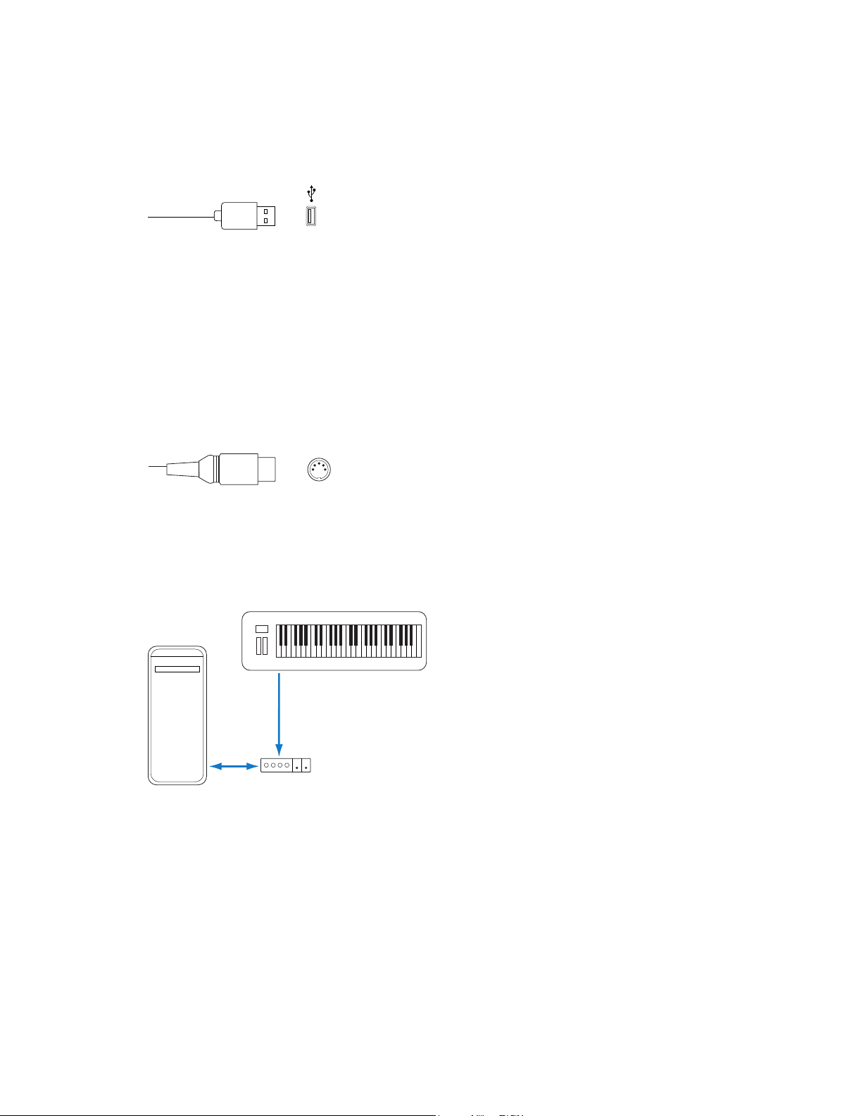
Connect a USB music keyboard to your computer
m If the keyboard has a USB port: Connect the USB cable from the keyboard to your computer.
USB (Universal Serial Bus)
Be sure to follow the instructions that came with the keyboard, which may include installing the
correct driver on your computer. Check the manufacturer’s website for the latest driver software.
If you are using a MIDI interface, be sure to follow the instructions that came with the interface.
Connect MIDI keyboards and modules
You can connect a MIDI keyboard to your computer to play software instrument patches or to
use with external MIDI devices such as synthesizers or sound modules.
When you connect a device with MIDI In and MIDI Out ports, be sure to connect the MIDI Out
port to a MIDI In port on a MIDI interface, and connect the MIDI In port on the keyboard to a
MIDI Out port on the MIDI interface using MIDI cables.
MIDI Connector
Connect a MIDI keyboard
Do one of the following:
m For keyboard controllers without tone generators: You only need to connect the MIDI Out port of
the keyboard to a MIDI In port on your MIDI interface, using a MIDI cable.
Computer
Out port
In port
MIDI interface
Chapter 2 Set up your system 15
Page 16
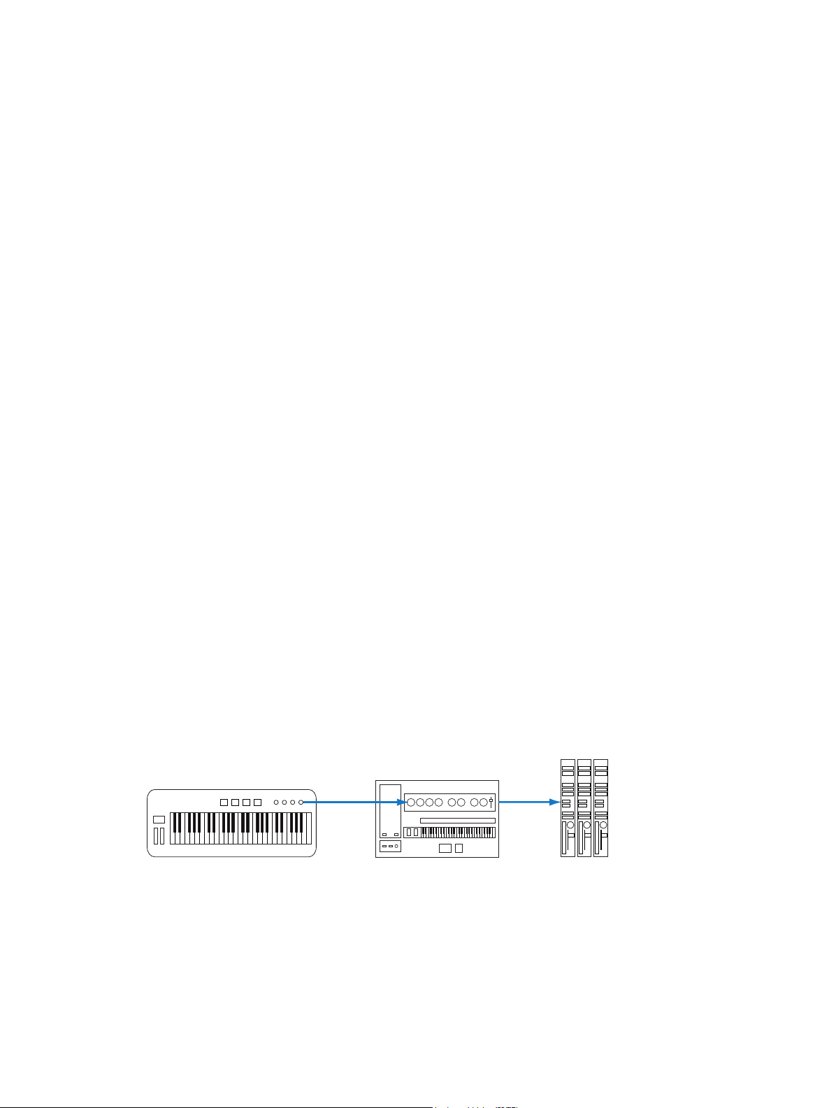
m For keyboards with tone generators: You should also connect the MIDI Out port of the MIDI
Keyboard
Tone generator
Keyboard
interface to the keyboard MIDI In port. If your MIDI interface oers more than one MIDI output,
connect any other tone generators (or other MIDI devices, such as control surfaces that require
bidirectional MIDI communication) to these.
Computer
In port Out port
In port Out port
MIDI interface
In port
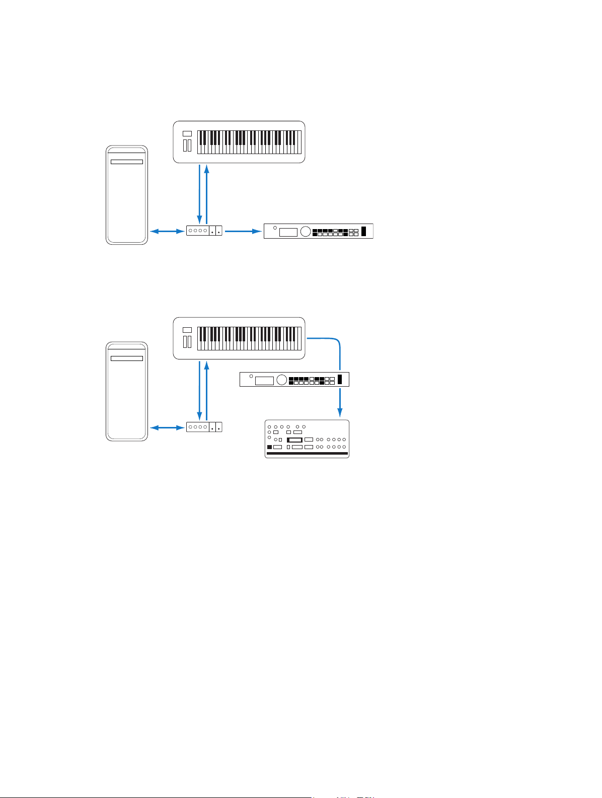
m If your MIDI interface has a single MIDI output: You need to connect the MIDI In of the second tone
generator to the keyboard MIDI Thru port. A third device can be connected to the MIDI Thru port
of the second unit, and so on.
Computer
In port Out port
Tone generator
In port Out port
MIDI interface
Tone generator
MIDI Thru port
In port
MIDI Thru port
In port
The MIDI Thru port replicates the signals coming into the MIDI In port of the device. It is
preferable to use a direct connection from the computer MIDI Out port to a device, rather than
chaining too many units, one after the other. Doing so can cause timing problems in the chain,
if numerous MIDI commands are sent quickly. This is due to the slight delays introduced by each
MIDI In to MIDI Thru transaction. As such, a multi input/output MIDI interface is recommended in
studios with several MIDI tone generators and controllers.
Chapter 2 Set up your system 16
Page 17

Multichannel MIDI devices
Multitimbral MIDI devices can simultaneously receive MIDI data on multiple MIDI channels. Each
MIDI channel can be assigned a tone or sound, such as piano, strings, bass, and so on.
To take full advantage of the capabilities of such multitimbral devices, you should use separate
MIDI Out ports (from the computer MIDI interface to the MIDI In ports) for each device.
MainStage is capable of channelizing MIDI data (routing it to MIDI channels 1 to 16) and sending
the channelized data to specic MIDI Out ports.
In eect, having a multi-output MIDI interface is something like having more MIDI channels. In
this scenario, it would be like having 64 independent MIDI channels—with 16 channels per port
(A, B, C, and D).
Not only does this allow you to play up to 64 dierent sounds simultaneously through
your tone generators, it also allows full MIDI control for each channel of each device. This
becomes increasingly important when arranging and orchestrating such a large number of
instrument parts.
If your computer oers several MIDI inputs, you can connect the MIDI outputs of other MIDI
expanders and controllers to it.
Turn o internally generated sounds
If your MIDI keyboard is also a sound generator, you will likely want to stop the device from
generating its own sounds while you are using it with MainStage, to avoid doubling notes
between the device and the MainStage patch you are playing.
Most MIDI synthesizers and other MIDI controllers with tone generation capabilities include a
function known as Local Control. By turning o this function, the device’s internal tone generation
is suppressed.
Suppress a device’s internally generated sounds
m On the device, turn on the Local O function.
If you can’t nd the Local O function in the MIDI menu of your keyboard, consult its manual
on sequencer use. Some keyboards allow you to select from Local, MIDI, or Both for each of
their Parts (individual MIDI channels/sounds in multitimbral MIDI devices). The MIDI setting, if
applicable to your keyboard, is the equivalent of Local O.
Chapter 2 Set up your system 17
Page 18
Connect audio devices
Audio devices overview
MainStage works with Core Audio-compliant audio devices, including FireWire, USB, ExpressCard,
and PCI audio interfaces. You can connect microphones, electronic musical instruments, and
other musical equipment to your computer, or to an audio interface or other audio device,
and use them with MainStage. For information about choosing audio drivers, see Audio
preferences on page 149.
MainStage can require a large amount of available RAM to play sample-based software
instruments or when you are using complex eects setups. It is recommended that you test
your system and the concerts you plan to use before you perform using MainStage to make
sure there is enough available memory to select and play the patches you want to use without
causing audio drop-outs or distortion.
Connect a microphone
You can connect a microphone to your computer to capture your voice, an instrument, or any
other sound to use as audio input when you perform. You can connect a microphone to your
computer’s audio input port, a USB port, or to an audio interface connected to your computer.
You can also use the built-in microphone in your computer.
Connect a microphone to your computer
Do one of the following:
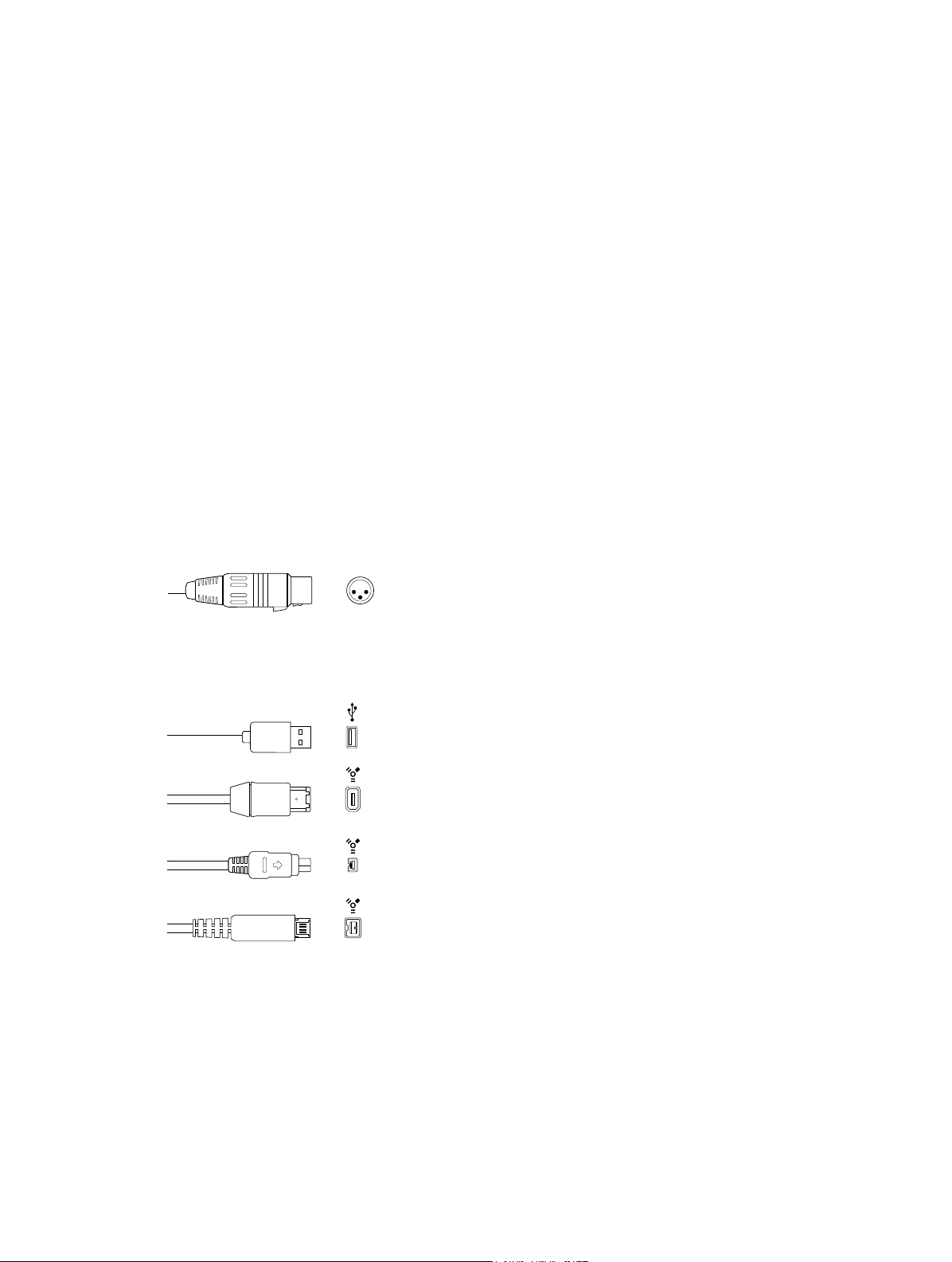
m Connect the microphone to an input on the audio interface using a standard XLR cable.
XLR connector
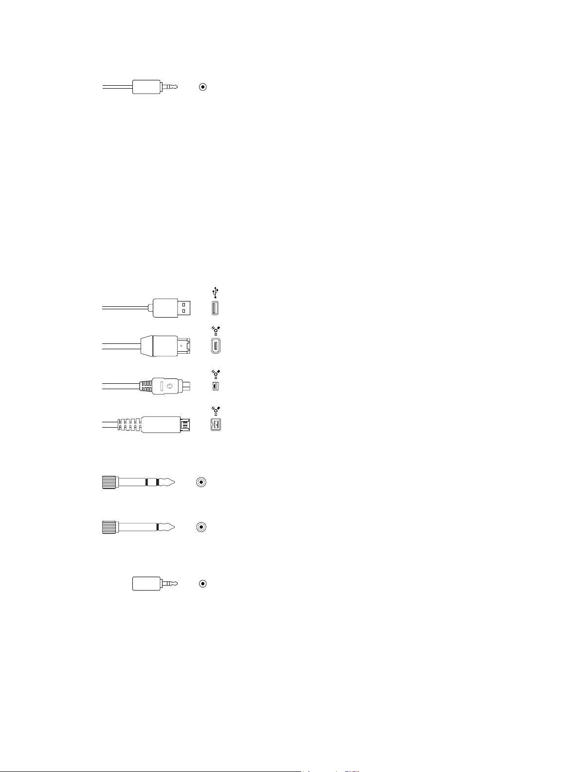
m Connect a USB microphone to a USB port on your computer. Choose the USB microphone as the
audio input source in the Audio preferences pane, then choose the input from the Input pop-up
menu on audio channel strips in your concert.
USB (Universal Serial Bus)
FireWire 400 (6-pin)
(Sometimes labeled iLINK)
FireWire 400 (4-pin)
FireWire 800 (9-pin)
m Connect an audio interface to your computer’s USB or FireWire port, then connect a microphone
to the audio interface.
m Connect an audio mixer or console to an audio interface, then connect the interface to
your computer.
Chapter 2 Set up your system 18
Page 19
m If your computer has an audio input port, connect the microphone to the audio input port, then
choose Built-in Input as the audio input source in the Audio preferences pane.
Stereo miniplug connector (unbalanced)
m If you are using your computer’s built-in microphone, choose Built-in Microphone as the audio
input source in the Audio preferences pane. No additional steps are necessary to connect
the microphone.
Connect an electric instrument
You can connect an electric instrument, such as an electric guitar or a bass, to your computer to
use with MainStage. You can set the guitar as the audio input for patches with an audio channel
strip and use the amps and pedalboard eects to shape your guitar sound. There are several
ways to connect an electric instrument to your computer.
Connect an electric instrument to your computer
Do one of the following:
m Connect an audio interface to your computer’s USB or FireWire port, then connect an electric
instrument to the audio interface.
USB (Universal Serial Bus)
FireWire 400 (6-pin)
(Sometimes labeled iLINK)
FireWire 400 (4-pin)
FireWire 800 (9-pin)
m Connect the electric instrument to a channel on the audio interface or the adapter cable, using a
standard 1/4-inch instrument cable.
1/4-inch Tip-Ring Sleeve (TRS) connector
1/4-inch Tip-Sleeve (TS) connector
m If your computer has an audio input port, connect an electric instrument to the audio input port
using an adapter cable. Choose Built-in Input as the input source.
Stereo miniplug connector (unbalanced)
After you connect an electric instrument, you choose the port to which it is connected as the
audio input source in the Audio preferences pane.
If you connect your electric instrument to an audio interface, check the manufacturer’s
specications to make sure the interface is compatible with OS X and Core Audio. Also make
sure the audio interface uses a format supported by your computer. Follow the manufacturer’s
instructions, which might include installing the correct driver on your computer.
Chapter 2 Set up your system 19
Page 20

Connecting some electric instruments, such as electric guitars, to your computer’s audio input
port may result in a low-level input signal. To increase the input signal, you can connect the
guitar to a preamplier and connect the preamplier to your computer.
Connect an audio interface
Using an audio interface, you can connect microphones, instruments, and other music
equipment to your computer to use with MainStage. You can also connect a mixer, speakers or
monitors, headphones, and other equipment to hear the audio output from your concert.
MainStage supports plug-and-play for audio interfaces, making it possible to connect and turn
on a new audio interface while MainStage is open. An alert appears when you connect a new
device, and prompts you to select and conrm the audio interface and driver that you want to
use.
All digital audio interfaces can be susceptible to latency—a noticeable delay between the time
the audio signal is produced and when you hear it. You should always attach your audio interface
directly to the computer, rather than through a hub or daisy-chaining it through another device.
Doing so can cause an unacceptable amount of latency, particularly with slower USB 1.1 devices.
Connect an audio interface to your computer
Do one of the following:
m Connect an audio interface to your computer’s USB or FireWire port.
USB (Universal Serial Bus)
FireWire 400 (6-pin)
(Sometimes labeled iLINK)
FireWire 400 (4-pin)
FireWire 800 (9-pin)
m Connect an audio interface to a PCIe (Peripheral Component Interconnect Express) card installed
in your computer. PCIe provides extremely high bandwidth and fast data transfer rates, allowing
audio input and output at the highest possible sample rates and bit depths.
m Connect an audio interface to an ExpressCard/34 slot installed in your computer. ExpressCard/34
supports both PCIe and USB 2.0 connectivity. ExpressCards available include audio interfaces,
hard disk controller (eSATA) cards, networking, wireless adapters, and more.
After connecting an audio interface to your computer, be sure to choose the audio interface
as audio input source in the Audio preferences pane. After choosing the audio interface as the
input device, you can set the individual inputs on the audio interface as the input source for the
audio channel strips in your concert.
Chapter 2 Set up your system 20
Page 21

Speakers and other audio devices
You can connect speakers or monitors to your computer to hear your projects with better audio
quality. A variety of speakers is available that you can connect to your computer or to your audio
interface. How you connect them depends on your system and the type of speakers you use.
After connecting speakers or monitors to your computer, be sure to set them as your audio
output. For details, see Audio preferences.
Eects plug-ins and MainStage
You can use the included eects plug-ins in MainStage channel strips. For more information
about the included eects plug-ins, refer to the MainStage Instruments and MainStage Eects
manuals. You can also use Apple and third-party Audio Units eects installed on your computer
in MainStage channel strips.
Some eects, including Space Designer, require intensive real-time processing of the audio
signal. Using Space Designer on individual patches can aect the performance of your concert,
and in some cases result in audio dropouts or glitches, particularly if you set the audio buer to
a smaller size. For this reason, it is recommended that you use Space Designer sparingly in your
concerts, and use a few Space Designer instances on auxiliary channel strips shared between
multiple patches, rather than in individual patches.
Some Audio Units plug-ins can introduce latency. Using eects that introduce latency, such
as compressors and limiters, can produce undesirable or unpredictable results during live
performance. Other Audio Units plug-ins, particularly instrument and amp modeling plug-ins,
require high levels of real-time processing and can aect the performance of your concert.
For information about adding and conguring plug-ins in MainStage, see Work with plug-ins
overview on page 65.
Chapter 2 Set up your system 21
Page 22

Workspace with
The MainStage interface
3
The MainStage window
You do all your work in MainStage in a single window. The MainStage window makes it easy to
work with your patches and your concert’s layout. When you open MainStage, the workspace lls
the center of the window, with inspectors and other editing areas on the sides and below. When
you are ready to perform, you can choose Perform mode to maximize computer performance
and display space for easy viewing on stage.
Toolbar
The main features of the MainStage window include:
•
Toolbar: Includes buttons for quick access to common commands and tools.
•
Activity Monitor: Shows your computer’s processor and memory usage, and shows the input
from your MIDI devices as you edit and perform.
•
Workspace: The “canvas” where you customize your onscreen layout, assign hardware controls
to screen controls, and view your concerts while you perform. You can also view assignments
and mappings for the concert.
•
Screen controls: The onscreen objects that correspond to the controls on your hardware
devices. You can add and arrange screen controls in the workspace, assign hardware controls
to screen controls, and then map them to parameters you want to control for each patch in
your concert.
•
Channel strips: Channel strips are where you build and customize your sounds. MainStage
channel strips feature Insert, Sends, and I/O menus as well as level meters, faders, pan knobs,
and other controls.
Activity Monitor
Inspector
screen controls
22
Page 23
•
Inspectors: Inspectors appear below (in Edit mode) or along the left side of the MainStage
window (in Layout mode) when you select dierent items onscreen. The inspectors allow you
to edit parameters and attributes for patches, sets, screen controls, channel strips, and the
concert. Most inspectors feature tabs that make it easy to quickly access the parameters you
want to edit.
To make working easier, MainStage features three dierent modes, each suited to a dierent task.
Some features are common to all modes, while others are exclusive to a particular mode.
•
You audition, edit, and organize your sounds and map screen controls in Edit mode.
•
You customize the visual arrangement of controls onscreen and make controller assignments
in Layout mode.
•
You use Perform mode when you perform live.
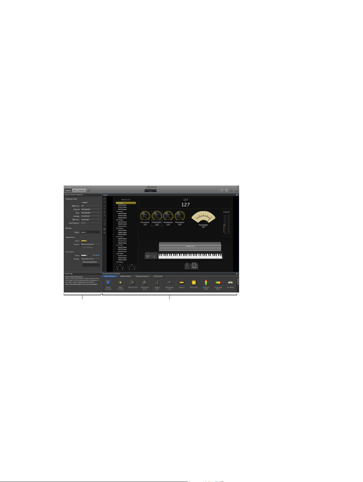
Layout mode
Layout mode is where you customize your onscreen layout. You drag screen controls into the
workspace and arrange them onscreen to customize your layout. You can also make connections
between your MIDI hardware and your concert in Layout mode, by creating controller
assignments between your MIDI hardware and the screen controls.
Screen Control Inspector Screen Controls Palette
•
Screen Control Inspector: View and edit parameters for screen controls in the workspace,
including hardware input, appearance, and certain types of MIDI output parameters.
•
Screen Controls Palette: Drag screen controls from the palette into the workspace to add them
to your onscreen layout. The palette has four tabs so that you can view all screen controls
or only one type of screen control. Panel controls appear as two-dimensional objects in the
workspace, while shelf controls appear on an adjustable three-dimensional shelf. The Smart
Controls screen control adapts the controls available depending on what patch you select.
•
Layout buttons: Along the left side of the workspace is a series of buttons that you can use to
quickly position selected screen controls in the workspace. You can align, distribute, and group
selected screen controls.
In Layout mode, unlike the other modes in MainStage, you cannot select or edit
individual patches.
For information about working in Layout mode, see Layout mode overview.
Chapter 3 The MainStage interface 23
Page 24
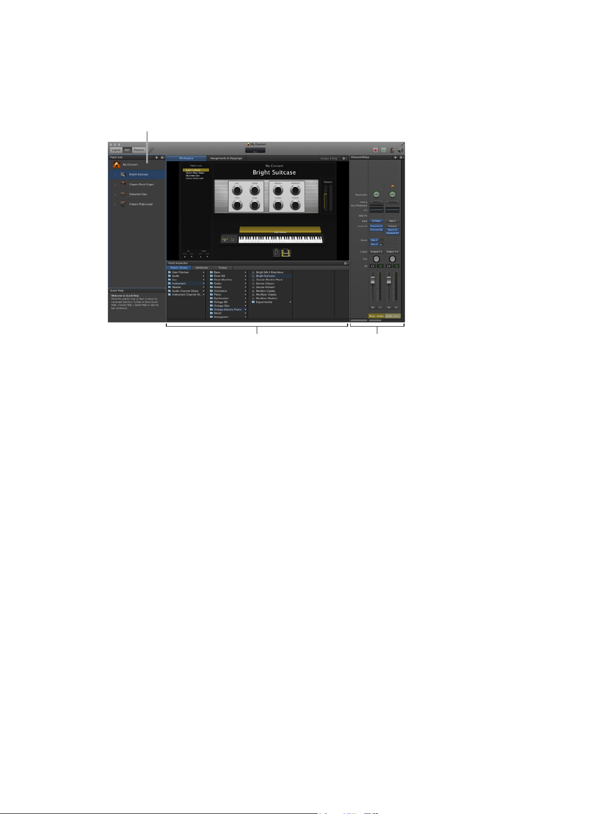
Edit mode
Patch List
Edit mode is where you create, edit, and organize your sounds. You can add patches, add
and edit channel strips, create keyboard layers and splits, and edit channel strip and plug-in
parameters. You also map screen controls to channel strip parameters and actions and edit
patch, set, and concert-level parameters in Edit mode.
Inspector (changes
depending on the selection)
•
Patch List: Shows the patches and sets in the concert. You can add patches and sets to the
Channel Strips area
Patch List, name them, and organize them. The Patch List includes an Action pop-up menu
with commands to create patches and sets, reset program change numbers, skip items, and
import and export patches and sets to use in other concerts.
•
Inspector: View and edit parameters for the currently selected patch, channel strip, screen
control, set, or for the concert. The name of the inspector indicates the type of item you are
currently inspecting.
•
Channel Strips area: View and edit the channel strips in your patches or at the concert or set
level. Channel strips appear in a vertical format with volume, pan, and other mixer controls.
You can also add channel strips and save channel strip settings.
•
Assignments & Mappings tab: Shows the assignments and mappings for the selected patch, set,
or concert. You can create new assignments and mappings, edit existing ones, and edit the
hardware input settings for an assignment.
For information about working in Edit mode, see Edit mode overview.
Chapter 3 The MainStage interface 24
Page 25
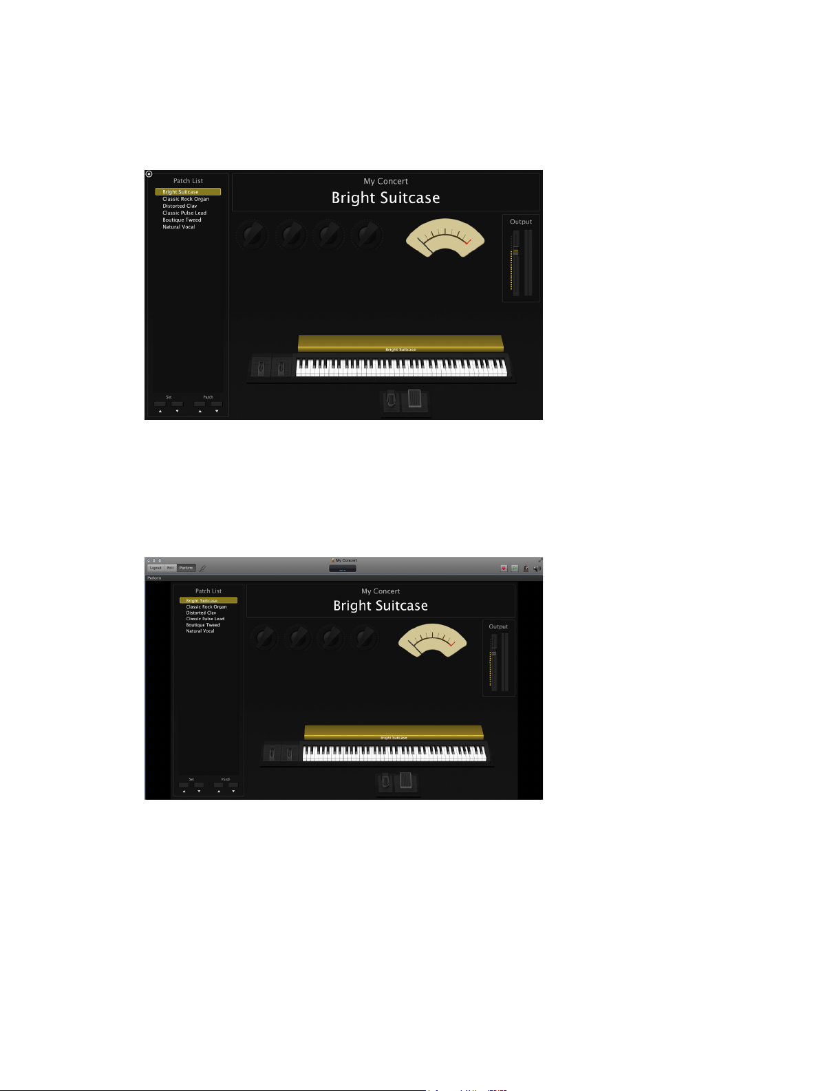
Perform mode
By default, Perform mode opens in full screen. The workspace lls your entire computer display
so that your screen controls are as large as possible for maximum readability. Perform in Full
Screen optimizes your display for live performance when you want to use MainStage exclusively
while you play.
You can choose to have Perform mode open in a window rather than full screen. The toolbar
remains visible so that you can switch modes using the Mode buttons, use the Panic or
Master Mute button and the Tuner, and view CPU and memory levels and MIDI input in the
Activity Monitor. The browsers and inspectors are hidden to maximize the size of the workspace,
making screen controls larger and easier to read in onstage situations. You can still access the
Finder and switch to other applications but cannot open plug-in windows.
Perform mode disables OS-level Auto Save, Spotlight, and Time Machine.
For information about performing live with MainStage, see Before the performance and the
following sections in the Perform live with MainStage chapter.
Chapter 3 The MainStage interface 25
Page 26

Resize the workspace
You can adjust both the horizontal and vertical size of the workspace to give more room to the
Patch List, the inspector, and the Channel Strips area.
Resize the workspace horizontally
1 Move the pointer to the space between the workspace and the inspector.
The pointer becomes a resize pointer.
2 Drag up or down to resize the workspace.
Resize the workspace vertically
1 Move the pointer to the space between the workspace and the Channel Strips area.
The pointer becomes a resize pointer.
2 Drag left or right to resize the workspace.
Chapter 3 The MainStage interface 26
Page 27
Get started with MainStage
4
Before you start
You can quickly start working in MainStage by choosing a concert template and trying out the
patch settings in the concert. This chapter provides a brief guided “walkthrough” you can follow
the rst time you open MainStage.
Before you start working in MainStage, you should connect the hardware equipment that you
plan to use, such as your keyboard controller, audio interface, instruments, or microphones, to
your computer. To use keyboard controllers and other MIDI devices with MainStage, the devices
should be capable of sending standard MIDI messages. If you’re not sure whether this is the case
for a particular device, consult the owner’s manual or the product website. For more information,
see MIDI devices overview and Audio devices overview.
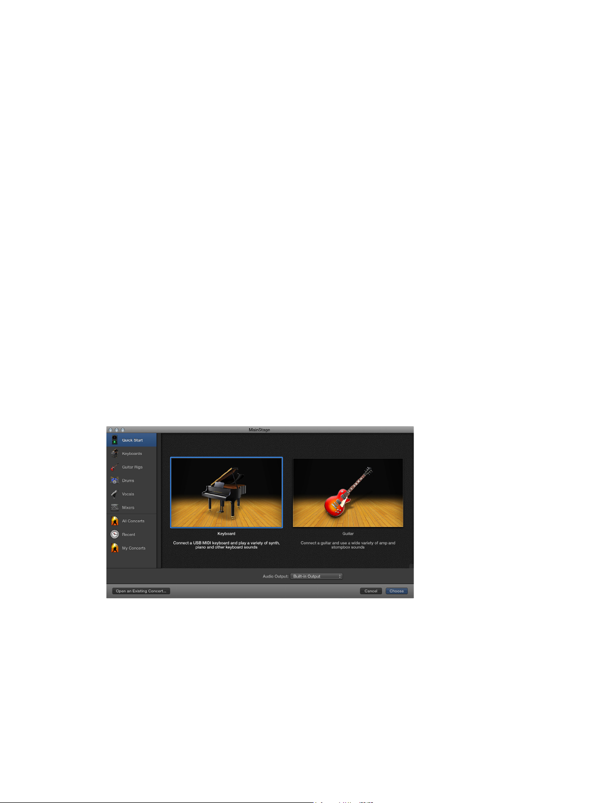
Choose a template
You start by opening MainStage and creating a new concert from a template.
MainStage includes templates for dierent musical instruments, including Keyboards, Guitar Rigs,
Drums, Vocals, and more. You can choose a concert template in the Choose Template dialog,
which appears the rst time you open MainStage and when you create a new concert or close
a concert.
27
Page 28

Open MainStage
m Double-click the MainStage icon in your Applications folder, or click the MainStage icon in the
Dock.
Choose a concert template
1 Choose File > New (or press Command-N).
2 In the Choose Template dialog, choose the devices you want to use for audio input and output
from the Audio Input and Audio Output pop-up menus.
3 Click the instrument category on the left you want to view templates for. You can also click Quick
Start and choose a simple keyboard or guitar template to start playing immediately.
A brief description below each template describes its features and intended use.
4 Scroll through the available templates to nd the one you want to use, then select it.
5 Click Choose, or double-click the template.
Choosing one of the Quick Start templates opens a new concert in Perform mode, so you can
start playing immediately. Choosing any other template opens a new concert in Edit mode. The
workspace appears in the center of the MainStage window, showing the screen controls in the
concert. To the left of the workspace is the Patch List, which shows the patches and sets in the
concert. The channel strips for the selected patch appear in the Channel Strips area to the right
of the workspace. The new concert may contain a single patch or several patches. Below the
workspace, the Patch Library is open, so you can easily audition dierent patch settings to nd
the one you want to use.
For more information about opening concerts, see Open and close concerts on page 87.
Chapter 4 Get started with MainStage 28
Page 29

Select patch settings in the Patch Library
When you open a concert or select a patch, the Patch Library opens in the Patch Inspector below
the workspace. The Patch Library contains a variety of patches optimized for the instrument the
concert is designed for. You can quickly audition patch settings in the Patch Library and choose a
setting for the selected patch. You can also search for patch settings by name.
Select a patch setting
1 Look through the settings in the Patch Library to nd the one you want to use.
2 Click the patch setting.
You can start playing the patch immediately using the selected patch setting.
Search for patch settings by name
1 Choose Find in Library from the Action pop-up menu in the upper-right corner of the
Patch Inspector.
2 Enter the name of the patch setting you want to nd.
3 Click Find.
The rst patch setting with the text you entered appears selected in the Patch Library.
4 To nd subsequent patch settings with the same name, choose Find Again in Library from the
Action pop-up menu.
Note: If you have saved multiple patches using the Save as Set command (or the Export as Set
command in MainStage 1.0) in the Action pop-up menu, the saved le appears as a patch in the
Patch Library unless you have selected a dierent location for saving the le. Clicking the saved
le in the Patch Library causes an alert to appear when the individual patches are opened from
the .patch le.
Chapter 4 Get started with MainStage 29
Page 30

Add a patch
You can add patches to the concert and organize them in the Patch List. The number of patches
is limited only by the amount of available memory in your system. When you add a patch to
a concert, the patch is selected so you can easily audition and select a patch setting from the
Patch Library.
When you add a patch, by default it takes the name of the channel strip added with it. You can
give each patch a custom name to make it easier to identify and distinguish between them.
Add a new patch
1 Click the Add Patch button (+), located in the upper-right corner of the Patch List.
The new patch appears in the Patch List, and the Patch Library is open in the Patch Inspector.
2 Select the patch setting you want to use from the Patch Library.
If you are using a keyboard controller, select a Keyboard patch. If you are playing an electric
guitar, select a Guitar Rig patch. For other instruments or vocals, you can choose a template from
the appropriate category or modify a keyboard or guitar template to suit your needs.
3 If the patch uses an audio channel strip, make sure the channel strip is set to use the correct
audio input, then gradually raise the volume fader on the channel strip until you hear sound on
the channel.
Rename a patch
1 Double-click the patch in the Patch List.
A eld appears with the patch name, which is selected.
Double-click the patch
name, then type a new
name.
2 Enter a new name in the patch name eld.
Chapter 4 Get started with MainStage 30
Page 31

Select and play patches
You access the patches in your concert by selecting them in the Patch List.
•
Using a MIDI controller, you can play patches that have a software instrument channel strip.
•
If you are playing an electric instrument connected to an audio interface, or are using a
microphone, you can use patches that have an audio channel strip.
Before playing through an audio channel strip, rst make sure that the channel strip is set
to receive input on the channel (or stereo pair of channels) to which your instrument or
microphone is connected.
For more information about organizing and selecting patches in the Patch List, see Edit mode
overview on page 37.
Select a patch
m Click the patch in the Patch List.
With the patch selected, try moving some controls on your MIDI controller and check to see if
the screen controls in the workspace respond. Some screen controls, including the keyboard,
modulation and pitch bend wheels, and sustain pedal screen controls, respond to appropriate
MIDI messages without needing to be assigned or mapped.
You can continue selecting and playing patches in the concert to nd sounds you want to
perform with or to use as a starting point for creating your own custom patches. You can also
add new patches and edit their channel strip settings to create your own unique sounds.
Add a channel strip
You can add channel strips to a patch to create layered sounds and keyboard splits. When you
add a channel strip to a patch, you choose the type of channel strip, the output, and other
settings. You can mix both types in a single patch.
Add a channel strip to a patch
1 Make sure the patch is selected in the Patch List.
2 Click the Add Channel Strip button (+) in the upper-right corner of the Channel Strips area.
3 In the New Channel Strip dialog, select the type of channel strip you want to create.
4 Choose the audio output for the channel strip from the Output pop-up menu.
5 For audio channel strips, choose mono or stereo format from the Format pop-up menu and
choose the audio input from the Input pop-up menu. For external instrument channel strips, also
choose the MIDI input, MIDI output, and MIDI channel from their respective pop-up menus.
Important: Audio channel strips can produce feedback, particularly if you are using a
microphone for audio input. When you add an audio channel strip, the volume of the channel
strip is set to silence, and Feedback Protection is turned on to alert you when feedback occurs on
the channel strip. When you add an external instrument channel strip, the volume of the channel
strip is set to silence, but Feedback Protection is turned o.
6 Optionally, you can add multiple channel strips to a patch by entering a number in the Number
eld. You can add up to the maximum number for a channel strip type.
7 Click Create.
A new channel strip appears in the Channel Strips area, highlighted to indicate that it is selected.
The Channel Strip Inspector appears below the workspace, showing dierent parameters for the
new channel strip.
Chapter 4 Get started with MainStage 31
Page 32

8 For audio and external instrument channel strips, gradually raise the volume fader until you hear
sound on the channel.
You can adjust channel strip output using the Volume fader, adjust pan position using the Pan
knob, and mute or solo the channel strip using the Mute and Solo buttons. For audio channel
strips, you can switch between mono and stereo format using the Format button. For software
instrument channel strips, you can choose a dierent instrument from the Input pop-up menu.
You can choose new channel strip settings, add and edit eects, add sends to busses, and
change the output using the controls on the channel strip.
You can also dene the key range for a channel strip, create transform and velocity graphs,
and lter various MIDI messages to a channel strip in the Channel Strip Inspector. For more
information about using channel strips in MainStage, see Channel strips overview on page 45.
Chapter 4 Get started with MainStage 32
Page 33

Change a channel strip setting
Click a category in this column
You can quickly change the instrument, eects, and other parameters for a channel strip by
selecting a new setting from the Channel Strip Library. The browser shows available settings for
the currently selected channel strip.
Select a new channel strip setting
1 Make sure that the channel strip you want to change is selected (highlighted).
2 In the Channel Strip Inspector, click the Channel Strip Library tab.
In the Channel Strip Library, channel strip settings appear as a series of folders with dierent
instrument and usage categories. If you have GarageBand or have one or more Jam Pack
collections installed on your computer, those settings appear below the built-in settings.
3 Click a category from the column on the left, then click subcategories from the columns on the
right until you see the settings you want.
to see the available choices.
You can also search for channel strip settings by name and perform other functions using the
Channel Strip Library. For more information about the Channel Strip Inspector, see Choose
channel strip settings on page 49.
Click the channel strip setting
you want to use from the
columns to the right.
Chapter 4 Get started with MainStage 33
Page 34

Learn a controller assignment
When you select a patch or a channel strip setting, some channel strip parameters respond to
the controls on your MIDI device instantly. MainStage responds to notes played on a keyboard
controller; volume, pan, and expression messages; modulation and pitch bend wheel messages;
and sustain pedal messages without your having to congure any screen controls to receive
these messages. For other controls such as faders, knobs, and buttons, you must assign these
hardware controls to MainStage screen controls before you can use them in your concert.
In MainStage, you assign hardware controls to screen controls in the Layout Inspector.
Learning controller assignments is a quick and easy method for assigning hardware controls to
screen controls.
Note: To be able to assign a hardware control to a screen control, the hardware control must
send standard MIDI messages. For more information, see MIDI devices overview on page 14.
Learn a new controller assignment
1 In the workspace, select the screen control you want to learn.
The selected control appears highlighted in blue.
2 Click the Assign & Map button at the top of the workspace.
The button glows red to indicate that the assignment process is active.
3 On your MIDI device, move the control you want to assign. Move faders and knobs through their
full range of motion, and press buttons exactly three times (not too quickly) to enable MainStage
to correctly learn the MIDI message types sent by these controls.
After the assignment process, the screen control responds when you move the corresponding
hardware control. This shows that the screen control is receiving MIDI input and is
correctly assigned.
4 While the Assign button is red, you can learn additional controller assignments by selecting
another screen control and moving the hardware control you want to assign to it.
5 When you are nished assigning controls, click the Assign & Map button again to turn o the
assignment process.
For information about working in the Assignments and Mappings pane, see Assignments and
mappings overview on page 76. For information about making controller assignments in Layout
mode, see Controller assignments overview on page 111.
Map a screen control
After you have learned controller assignments for the screen controls you want to use, you can
map the screen controls to the parameters in the patches you want to control when you are
performing. You will likely want to map screen controls to parameters in each patch in a concert,
so that you can easily access and modify the parameters you want for each patch when you
perform live. You can also map parameters at the concert level to control master volume, view
master levels, or modify concert-wide eects.
There are two ways to map screen controls to parameters: by visually selecting parameters
on channel strips or plug-in windows, or by choosing parameters in the Parameter Mapping
browser. To learn how to map a screen control to a channel strip or plug-in parameter, see Map
screen controls to channel strip and plug-in parameters on page 69. To learn how to map a
screen control to an action, see Map screen controls to actions on page 71.
Chapter 4 Get started with MainStage 34
Page 35

Map a screen control to a parameter
Click the screen control you
1 In the workspace, click the screen control you want to map.
The screen control is highlighted in blue. The Screen Control Inspector appears below the
workspace, showing the parameters for the selected screen control. The Screen Control Inspector
includes Attributes and Mapping tabs as well as a tab labeled Unmapped (until you map the
screen control).
2 Click the Map Parameter button (or press Command-L).
The Screen Control Inspector opens to the Unmapped tab, showing the Parameter Mapping
browser. The Map Parameter button lights red to indicate that mapping is active.
3 Do one of the following:
•
To map the screen control to a channel strip parameter: Click the control for the parameter on
the channel strip in the Channel Strips area.
•
To map the screen control to a plug-in parameter: Double-click the plug-in in the Inserts
section of the channel strip to open the plug-in window, then click the parameter in the
plug-in window.
want to map to a parameter.
Click the parameter
in a channel strip or
plug-in window.
4 You can continue mapping additional screen controls by clicking them in the workspace and
then clicking the corresponding parameters in a channel strip or plug-in window.
5 When you are nished, click the Map Parameter button again (or press Command-L again) to
turn o mapping.
Chapter 4 Get started with MainStage 35
Page 36

Try out Perform mode
After learning controller assignments and mapping screen controls, you can try playing your
patches as you would in a performance. You can have the workspace occupy the entire screen,
presenting the screen controls as large as possible for easy viewing in concert environments,
or you can view the workspace in a window, so you can use the toolbar buttons and access
other applications.
Switch to Perform mode
Do one of the following:
m Choose View > Perform in Full Screen (or press Command-4).
Note: By default, the Perform button opens the workspace in full screen. For information about
changing this preference, see Display preferences on page 151.
m Click the Perform button in the toolbar.
View the workspace in a window
m Choose View > Perform in Window (or press Command-3).
You can use either workspace view to play the patches you added or modied and use the
controls on your MIDI controller to modify the parameters you have mapped to screen controls.
Use Quick Help
You can view a brief description of windows, controls, and other elements of the MainStage
interface without leaving the application or interrupting your workow. In both Edit mode and
Layout mode, Quick Help is available in the lower-left corner of the MainStage window.
View Quick Help
m Choose Help > Quick Help.
Some Quick Help topics include links to more detailed information. You can access the additional
information by pressing Command-Shift-H while the pointer is over the corresponding control
or area.
Chapter 4 Get started with MainStage 36
Page 37

Work in Edit mode
5
Edit mode overview
In Edit mode, you add and edit patches to create your custom sounds, choose patch settings
in the Patch Library, organize and select patches in the Patch List, edit patch parameters in the
Inspector, and map screen controls to parameters and actions. You can create custom patches
in Edit mode and organize them in the Patch List so that you can easily access them when you
perform.
Patches are the individual sounds you play using your keyboard controller (for MIDI keyboardists)
and the eects setups you use with your guitar, microphone, or other instrument (for guitarists,
vocalists, and other instrumentalists). MainStage patches can contain multiple channel strips,
each with a dierent instrument or eects setup.
Some basic patch operations, including adding and naming patches, selecting and naming
patches, and adding channel strips to patches, are described in the Get started with
MainStage chapter.
If MainStage is currently in Layout or Perform mode, click the Edit button in the top-left corner of
the MainStage window to begin working in Edit mode.
As you work in Edit mode, you can use the Activity Monitor in the toolbar to view the current
CPU and memory information as well as received MIDI messages. You can show or hide the
CPU and memory meters in the Display pane of MS preferences. For information, see Display
preferences.
37
Page 38

Work with patches in Edit mode
Select items in the Patch List
All of the patches and sets in a concert appear in the Patch List. To select an item in the Patch List
in Edit mode, you can click the item, use key commands, or type its patch number or the rst few
letters of its name. The patch number appears to the left of the patch icon in the Patch List.
You can also skip patches or sets in the Patch List. When a patch or set is skipped, using the
Command key together with the arrow keys to select items passes over the patch or set and
the next (non-skipped) item is selected. However, you can still select the item by clicking it or
using the arrow keys alone. Skipped items are also skipped when you use the patch selector in
Perform mode.
Select a patch in the Patch List
1 In the Patch List, located to the left of the workspace, click the patch.
Click a patch in the
Patch List to select it,
and start playing.
2 With the patch selected, you can start playing instantly.
Select a patch using key commands
m To select the previous (higher) patch: Press the Up Arrow key.
m To select the next (lower) patch: Press the Down Arrow key.
m To select the previous patch: Press Command–Up Arrow.
m To select the next patch: Press Command–Down Arrow.
m To select the rst patch in the previous set: Press Command–Left Arrow.
m To select the rst patch in the next set: Press Command–Right Arrow.
Note: When you use the Command-Arrow key commands listed above to select dierent
patches, the selected screen control remains selected in the workspace. This makes it easy to see
how a screen control is congured in dierent patches.
Select a patch by typing its patch number
1 Click the border of the Patch List to select it.
2 With the Patch List selected, type the patch number.
Chapter 5 Work in Edit mode 38
Page 39

Select a patch or set by typing its name
1 Click the border of the Patch List to select it.
2 With the Patch List selected, start typing the name of the patch. Once you type enough letters to
uniquely identify its name, the patch or set is selected.
You can also select a patch by typing its name in Perform mode. For information, see Select
patches by typing on page 121.
Skip a patch or set
1 Select the patch or set in the Patch List.
2 Choose Skip from the Action pop-up menu for the Patch List.
The item appears as a thin line in the Patch List.
Set a skipped patch or set to no longer be skipped
1 Select the item (patch or set) in the Patch List.
2 Choose Don’t Skip from the Action pop-up menu for the Patch List.
The item returns to full size in the Patch List.
Copy, paste, and delete patches
You can copy, paste, and duplicate patches in the Patch List using the standard OS X menu and
key commands or by Option-dragging. When you paste or duplicate a patch, it includes any
mappings made to parameters in the original patch. You can also delete a patch if you no longer
want to use it in the concert.
Copy a patch
1 Select the patch in the Patch List.
2 Choose Edit > Copy (or press Command-C).
Paste a patch
m After copying a patch, choose Edit > Paste (or press Command-V).
Delete a patch
1 Select the patch in the Patch List.
2 Choose Edit > Delete (or press the Delete key).
Reorder and move patches in the Patch List
When you add a patch to a concert, the new patch appears below the currently selected patch in
the Patch List. You can drag patches in the Patch List to reorder them.
MainStage includes a Move Again command that lets you easily move selected patches multiple
times. You can use Move Again when you drag, paste, create, or delete patches in the Patch List.
Reorder patches in the Patch List
m Drag patches up or down in the Patch List until they appear in the order you want.
Move patches repeatedly
m After moving the patch once, choose Move again from the Action pop-up menu (or press Shift-
Option-M) for each additional move.
Chapter 5 Work in Edit mode 39
Page 40

Create a patch from several patches
You can create a patch by combining several existing patches. The new patch contains all of the
channel strips of the selected patches.
Create a patch from several existing patches
1 In the Patch List, select the patches you want to use to create the new patch.
2 Choose Create Patch from Selected Patches from the Action pop-up menu at the upper-right
corner of the Patch List.
The new combined patch appears in the Patch List, labeled “Untitled Patch.”
3 Double-click the name and type a name for the combined patch.
Note: Creating a patch with more than three channel strips can aect performance, particularly if
they use a large number of plug-ins or processor-intensive plug-ins.
Set the time signature for patches
You can set the time signature for a patch. Time signatures can be used with the Playback
plug-in and also control the beats for the metronome. When you set the time signature for a
patch, it overrides any concert- or set-level time signature.
Set the time signature for a patch
1 In the Patch Inspector, select the Attributes tab.
2 In the Attributes tab, select the Has Time Signature checkbox.
3 Double-click the number in the eld at the right, and enter the number of beats for one measure
of the time signature.
4 Choose the beat value from the pop-up menu at the right.
Change the tempo when you select a patch
You can give a patch its own tempo setting so that when you select the patch, the tempo
changes to the patch tempo setting. MainStage uses the new tempo until you select another
patch or set with its own tempo setting, tap a new tempo, or until MainStage receives tempo
information from incoming MIDI messages. For more information about using and changing
tempo in MainStage, see Tempo overview on page 90.
Change the tempo using a patch
1 In the Attributes tab of the Patch Inspector, set the patch tempo using the Change Tempo To
value slider.
2 To activate the patch tempo when the patch is selected, select the Change Tempo To checkbox.
Select the checkbox
and set the tempo using
the slider.
Chapter 5 Work in Edit mode 40
Page 41

Set program change and bank numbers
When you add a patch to a concert, the patch is given a MIDI program change number (the
lowest available number) until all available program change numbers are taken. You can select
patches using program change numbers in performance by assigning buttons on a MIDI
device to send program change messages. The program change number can be edited in the
Patch Inspector.
To select more than 128 patches, you can also set the bank number for a patch.
You can reset program change numbers for all active (non-skipped) patches in a concert. When
you reset program change numbers, patches are assigned program change numbers based on
their order in the Patch List, starting from the top. The program change numbers for skipped
(inactive) patches are not reset.
To select patches by bank, rst send the bank select message, then the program change
message.
Note: Some devices send program change numbers in the range of 0–127, while other devices
use the range of 1–128. You can set which range of program change numbers MainStage uses in
the MIDI Preferences pane.
Edit the program change number for the selected patch
1 In the Attributes tab of the Patch Inspector, select the Program Change checkbox.
2 Using the value slider, set the program change number.
Set the bank number for the selected patch
1 In the Attributes tab of the Patch Inspector, select the Bank Select checkbox.
2 Using the value slider, set the bank number.
Reset program change numbers for active patches in a concert
m Choose Reset Program Change Numbers from the Action pop-up menu for the Patch List (or
press Command-Shift-Option-R).
Reset program change and bank select numbers in the Patch List
m Choose Reset Bank and Program Numbers from the Action pop-up menu for the Patch List.
Show bank and program change numbers in the Patch List
m Choose Show Bank and Program Numbers from the Action pop-up menu for the Patch List.
The MIDI standard allows program change numbers with values from 0 to 127. If all available
program change numbers in a concert are already in use, any new patches added to the concert
are given program change number zero (0), but the number is inactive (the checkbox is not
selected). Bank changes are not supported.
Chapter 5 Work in Edit mode 41
Page 42

If you edit a program change number so that it is the same as an existing program change
number, the word “Duplicate” appears in red next to the Program Change value slider. If two or
more patches have the same program change number, and the numbers are active, the patch
that appears rst (highest) in the Patch List or patch selector is selected when you send the
program change message with the corresponding value.
Using Reset Bank and Program Numbers sets the bank automatically based on sets. This allows
you to browse sets using bank select numbers, and browse patches using program change
numbers, to access a large number of patches.
You can assign buttons and other controls to send program change messages and use
them to select patches in the concert. For information about assigning buttons, see Button
assignments on page 112 .
Defer patch changes
By default, when you switch patches, the new patch is ready to play immediately. You can “defer”
a patch change so that the patch change occurs after the last note of the previous patch has
been released or sustained.
Defer a patch change
m In the Attributes tab of the Patch Inspector, select the Defer Patch Change checkbox.
Note: Deferring patch change works in Perform mode but does not work when you are editing
patches in Edit mode. You can defer incoming MIDI program changes and buttons mapped
to actions but not defer patch changes made by clicking the Selector object or using the
arrow keys.
Instantly silence the previous patch
Sometimes you may want the sound of the previous patch to continue after you select a new
patch, as when you want to sustain a chord pad while soloing over it. At other times, you may
want to silence the sound of the previous patch instantly when you select a new patch.
Instantly silence the previous patch when you select a patch
m In the Attributes tab of the Patch Inspector, select the Instantly Silence Previous Patch checkbox.
Change patch icons
Each patch has an icon that appears in the Patch List next to the patch name. By default, the
patch icon shows the type of channel strip created when the patch was added. You can choose a
new icon for a patch and use icons to visually distinguish patches in the Patch List.
Change the icon for a patch
m In the Attributes tab of the Patch Inspector, choose an icon from the Icon pop-up menu.
Chapter 5 Work in Edit mode 42
Page 43

Change the tuning for a patch
By default, patches use the same tuning method as the concert (or the set, if they are in a set
with its own tuning method). You can change the tuning for a patch so that it uses a dierent
tuning. When you change the tuning for a patch, it overrides any concert- or set-level tuning
method. Available tuning methods include:
•
Use parent tuning: The patch uses the same tuning as the set (if it is in a set with its own tuning
method) or the concert.
•
Equal tempered tuning: The standard tuning for most Western music, with an equal distance
between all semitone intervals.
•
Fixed: Lets you choose from a number of xed tuning scales and keys. Fixed Tuning mode
tunes musical keys (to dierent degrees) for scaled tuning systems, and delivers a key
signature character. When playing mostly white keys (in the Pure setting, and with C as the
root key), C major is the main focus, and tuning is scaled to that chord. An A major chord that
is played immediately after a C major (and is therefore subject to C major scaled tuning) is
aected somewhat by the scaled tuning eect, but will not sound completely tempered. If
you normally play polyphonic music, this mode (when using the Pure setting) will sound most
pleasing to your ears. The Fixed Tuning scales are ideal for a number of baroque and medieval
instruments and styles of music.
•
User: Allows you to detune (set the deviation from equal tempered tuning) each semitone
in steps.
•
Hermode Tuning: Because all tuning requirements cannot be satised simultaneously with any
one Hermode Tuning setting, allows you to set dierent Hermode Tuning modes and degrees
of eect.
When you choose Fixed, Hermode, or User as the tuning method, additional tuning controls
appear in the Tuning tab. You can edit these controls to adjust the chosen tuning.
Change the tuning method for a patch
1 In the Patch Inspector, select the Tuning tab.
2 Choose the tuning you want the patch to use from the Method pop-up menu.
Edit Fixed Tuning parameters
m When Fixed Tuning is chosen, edit any of the following parameters:
•
Type pop-up menu: Choose between the most important historic tuning scales, as well as a
few others.
•
Root Key pop-up menu: Choose a global key (C-B) for the chosen scale. This provides an easy
way to reference the chosen scale to any root note.
•
Copy to User button: Copies the chosen scale to use as a basis for a User tuning.
Edit Hermode Tuning parameters
m When Hermode Tuning is chosen, choose a mode from the Type pop-up menu:
•
Classic (3/5-all): This mode provides a broad and regular tuning of pure 5ths and 3rds. In cases
of conict, the degree of purity is temporarily reduced. This mode can be used for all types
of music. The value of the Depth parameter indicates the degree of the 5th and 3rd purity. A
setting of 100% determines maximum purity. A 10% value is the lowest purity setting. O sets
the tuning to an equal tempered scale.
Chapter 5 Work in Edit mode 43
Page 44

•
Pop/Jazz (3/5/7-all): 5ths, 3rds, and 7ths are changed in this mode. It is great for Pop and Jazz
styles, especially when using sustained chords. It is less suitable for polyphonic music because
the detuning of the natural 7th is signicant. This mode should always be used with a Depth
of 90% or 100% because other values will render the natural 7th acoustically ineective.
•
Baroque (3/5-adaptive): This mode tunes pure 5ths and 3rds (with changing characteristics). In
tonal music, with a clear harmonic center, the middle chords are tuned very purely, whereas
more distant chords are tuned with less purity. If the harmonic center becomes unclear, all
chords are tuned with equal purity. As with the other mode parameters, a Depth value of
100% determines the highest purity, and a value of 10%, the lowest purity.
m Depth slider: Drag to set the degree of eect between 0% and 100%.
Edit User Tuning parameters
m When User Tuning is chosen, edit any of the following parameters:
•
Semitone boxes: Detune each semitone in steps, by dragging vertically in each semitone box
until you reach the value you want. Alternately, you can double-click in each semitone box,
and enter a value. Press Return or click in another box to exit text entry mode.
•
Reset button: Resets all of your tuning adjustments to their default values.
•
Upper slider: Determines the deviation (from the equal tempered scale) in the treble end of the
sound. The higher the value, the farther down the low notes are tuned. A setting of 0 results in
an equal tempered scale tuning.
•
Stretch Lower slider: Determines the deviation (from the equal tempered scale) in the bass end
of the sound. The higher the value, the further down the low notes are tuned. A setting of 0
results in an equal tempered scale tuning.
•
Root Key pop-up menu: Allows you to choose a global key (C-B) for the chosen scale. This
provides an easy way to reference the chosen scale to any root note.
Chapter 5 Work in Edit mode 44
Page 45

Work with channel strips in Edit mode
Channel strips overview
Channel strips are the building blocks of your patches. They contain the instruments and eects
for the sounds you use in performance. MainStage channel strips use the channel strip interface
common to many DAW and mixing applications. The main features of MainStage channel strips
are shown below:
Expression control
Settings menu
Channel EQ
MIDI plug-in slot
Input slot
Effect slots
Send slots and Send
Level knob
Output slot
Pan knob
Volume fader
Mute and Solo buttons
•
Icon: Shows the type of channel strip for easy identication.
•
Expression control: Allows you to quickly adjust the expression value of the channel strip.
•
Settings menu: Allows you to load and save the entire routing conguration of a single channel
strip, including all loaded plug-ins and settings.
•
Channel EQ: Allows you to add an EQ eect to sculpt the sound of the channel strip signal
before applying other eects.
•
MIDI plug-in slots: Allow you to insert MIDI plug-ins into instrument channel strips.
•
Eect slots: Allow you to insert plug-ins into audio, instrument, aux, and output channel strips.
•
Send slots: Allow you to route a channel strip’s signal to an aux channel strip. Sends are
commonly used to apply the same eect or eects to several signals.
•
Send level knob: Controls the amount of signal sent to an aux channel strip. This knob appears
when a Send slot is activated.
•
Eect slot: Sets the channel strip’s input source. Depending on the channel strip type, it can
be a physical input, a bus, or a software instrument plug-in—in this case it is known as an
Instrument slot.
•
Output slot: Sets the channel strip’s output path. It can be a physical output or a bus.
•
Pan/Balance knob: On a mono channel strip, the Pan/Balance knob controls the position of the
signal in the stereo image. On a stereo channel strip, it controls the relative level of the left and
right signals at their outputs.
Chapter 5 Work in Edit mode 45
Page 46

•
Volume fader: Sets a channel strip’s playback volume.
•
Mute button: Mutes and unmutes the channel strip.
•
Solo button: Solos and unsolos the channel strip.
•
Level meter: Displays a channel strip’s playback level.
•
Peak level display: Updates during playback to show the highest peak level reached.
In MainStage, you can use audio, software instrument, and auxiliary (aux) channel strips in your
patches and sets, and also at the concert level. You can also use external instrument patches to
“play” external hardware devices and ReWire applications. You can adjust the volume level using
the Volume fader, adjust the pan position using the Pan knob, and mute or solo the channel strip
using the Mute and Solo buttons.
A MainStage concert can have a maximum of 1023 software instrument channel strips, 512 audio
channel strips, 256 external instrument channel strips, and 256 auxiliary (aux) channel strips.
You can add eects using the Insert slots, send the signal to an auxiliary channel (aux) using the
Sends slots, and choose a dierent output from the Output slot. For audio channel strips, you can
change the format between mono and stereo using the Format button. For software instrument
channel strips, you can change the instrument using the Instrument slot. You can also choose,
copy, and save channel strip settings, choose a dierent channel strip type, or reset the channel
strip from the Settings menu.
To learn how to add a channel strip, see Add a channel strip on page 31. To learn how to change
a channel strip setting, see Change a channel strip setting on page 33. For information about
the included instrument and eects plug-ins, see the MainStage Instruments and MainStage
SEects manuals.
Show signal ow channel strips
In addition to the channel strips in a patch, you can view and edit signal ow channel strips in
the Channel Strips area. Signal ow channel strips include the Output and Master channel strips
for the concert, auxes that are receiving signal from a channel strip in the patch, and any set- or
concert-level channel strips that are available when the patch is selected. You can also view
signal ow channel strips at the set level.
When you show signal ow channel strips, channel strips at the concert level, including Output
and Aux channel strips, include a small concert icon near the top of the channel strip to make it
easy to distinguish them from patch-level channel strips. Channel strips at the set level include a
small folder icon so they can also be easily distinguished.
You can edit signal ow channel strips in the Channel Strips area. For example, you can
adjust the volume fader or pan slider of a signal ow channel strip or add eects to an aux
channel strip.
Show signal ow channel strips for the selected patch
m Choose Show Signal Flow Channel Strips from the Action pop-up menu in the upper-right corner
of the Channel Strips area.
Chapter 5 Work in Edit mode 46
Page 47

Show the metronome channel strip
You can show the metronome channel strip in the Channel Strips area, where you can change its
volume or change the metronome sound.
Show the channel strip for the metronome
m Choose Show Metronome Channel Strip from the Action pop-up menu in the upper-right corner
of the Channel Strips area.
To hide the metronome channel strip, choose Hide Metronome Channel Strip from the Action
pop-up menu.
Create an alias of a channel strip
You can create an alias of a channel strip and use the alias in dierent patches or sets. Aliases
allow you to share highly memory-intensive plug-ins, such as third-party multichannel
instruments and samplers, between dierent patches, rather than creating multiple instances of
these plug-ins. In some cases, creating an alias can be more ecient (use fewer resources) than
adding a concert- or set-level channel strip.
Create a channel strip alias
1 In the Channel Strips area, select the channel strip.
2 Choose Edit > Copy, or press Command-C (default).
3 In the Patch List, select the patch in which you want to use the alias.
4 Choose Edit > Paste as Alias, or press Command-Option-V (default).
The alias is pasted after the last channel strip in the patch (but before any signal ow channel
strips, if they are visible). An alias icon appears near the top of the alias to distinguish it from the
channel strips in the patch.
You can use an alias in multiple patches or sets. When you change settings on the original
channel strip (with the exception of volume, pan, and expression), those changes are reected
in the aliases of the channel strip. You may want to audition each patch that uses an alias after
changing the settings of the original channel strip, to make sure it sounds the way you want.
You can create an alias of a multi-output instrument, such as the EXS24 mkII, to use in another
patch or set in the concert. When you copy a multi-output instrument to create an alias, be
sure to select all of the aux channel strips for the instrument so that the complete multi-output
instrument is pasted as an alias. For information, see Use multiple instrument outputs on
page 56.
Chapter 5 Work in Edit mode 47
Page 48

Add a patch bus
In addition to the 64 global busses available for concert-wide routing, you can add patch-
specic busses for routing inside a patch—using patch busses does not contribute to the
global maximum. They can be used for a variety of purposes, such as a local volume control for
layered patches.
A patch bus is available only for the patch you add it to. Patch busses for each patch are
numbered sequentially starting from 1. Two dierent patches may each have a patch bus named
“Patch Bus 1,” but each one is unique to the patch it was added to. The signal ows of the two
patch busses are completely independent.
Add a patch-specic bus
m Click a Send slot, then choose Patch Bus > Insert Patch Bus from the shortcut menu.
A new patch bus appears in the Send menu for the patch.
Channel Strip Inspector
You can add instruments to software instrument channel strips and add eects to any channel
strip in the Channel Strips area. You edit channel strip parameters in the Channel Strip Inspector,
which appears below the workspace when the channel strip is selected in the Channel Strips
area. You can set the key range and velocity oset, create a controller transform, and lter MIDI
control messages to the channel strip. You can also rename the channel strip and change the
channel strip color and icon. The four tabs of the Channel Strip Inspector provide the following
functions:
•
Channel Strip Library and Plug-In Library: With a channel strip selected, you can select channel
strip settings from the Channel Strip Library. With an Insert slot selected, you can select
settings for the plug-in from the Plug-in Library.
•
Attributes: You can rename the channel strip and select a dierent channel strip color and icon.
•
MIDI Input: You can create controller transforms in the MIDI Input tab. For software instrument
and external instrument channel strips, you can also choose the MIDI input device, lter MIDI
input, transpose the instrument, and create velocity scaling graphs.
•
Layer Editor: For software instrument and external instrument channel strips, you can dene
the key range, set oating split points, and set the minimum and maximum velocity for the
channel strip.
Using the Channel Strip Library you can access any available channel strip. Some channel strips,
however, include plug-ins (particularly Space Designer) not suited for live performance because
of their intensive CPU usage. Using these channel strips can aect the performance of your
concert, resulting in audio dropouts and other issues.
Chapter 5 Work in Edit mode 48
Page 49

Surround eect plug-ins cannot be used with MainStage. If you choose a channel strip setting
containing a surround eect, the unused eects are shown disabled (gray, with a diagonal line
running through the eect name).
Choose channel strip settings
You can quickly change the instrument, eects, and other parameters for a channel strip by
choosing a new channel strip setting. You can choose a new channel strip setting from the
Channel Strip Library or from the Settings menu at the top of the channel strip.
You can also search for channel strip settings by name.
Choose a channel strip setting from the Channel Strip Library
1 In the Channel Strips area, select the channel strip you want to change.
The selected channel strip is highlighted with a blue outline.
2 In the Channel Strip Inspector, click the Channel Strip Library tab.
Available settings for the channel strip appear in the Channel Strip Library. MainStage built-in
channel strip settings appear in a series of folders with dierent instrument categories. If you
have GarageBand installed, or have one or more Jam Packs installed on your computer, those
settings appear below the built-in settings.
3 Click a category from the column on the left, then click subcategories from the columns on the
right until you see the settings you want.
You can select a recent channel strip setting by clicking Recent in the column on the left and
then selecting a recent setting from the second column.
Choose a channel strip setting from the Settings pop-up menu
m Click the Settings button at the top of the channel strip, then choose a new setting from the
pop-up menu that appears.
When you choose new channel strip settings from the Settings pop-up menu, the selected
channel strip setting does not appear selected in the Channel Strip Library.
Search for channel strip settings in the Channel Strip Library
1 In the Channel Strip Inspector, click the Channel Strip Library tab.
2 Choose Find in Library from the Action pop-up menu in the upper-right corner of the Channel
Strip Inspector.
3 In the dialog that appears, enter the text you want to search for.
The channel strip with the text in its name appears selected in the library.
4 If more than one channel strip includes the search text, choose Find Next in Library from the
Action pop-up menu to cycle through the channel strips with names containing the text.
Chapter 5 Work in Edit mode 49
Page 50

5 To change the channel strip setting, click the name of the new setting in the Channel
Type a new name in the field.
Choose a color from the
Strip Inspector.
The Channel Strip Library shows all available channel strip settings, including settings that may
not be useful in MainStage. If you choose a channel strip setting containing plug-ins not usable
in MainStage, the plug-ins appear with a bold diagonal line in the Channel Strips area.
Rename channel strips
When you add a channel strip to a patch, the channel strip has a default name. You can rename
channel strips to distinguish your custom settings from the default ones.
Rename a channel strip
m In the Attributes tab of the Channel Strip Inspector, select the name in the Name eld and enter
a new name.
Change channel strip colors
Each channel strip has a color, which appears at the bottom of the channel strip and as a layer
above the keyboard screen control in the workspace and the Layer Editor. You can change the
color of a channel strip to make it easier to visually distinguish channel strips.
Change the color of a Software Instrument channel strip
m In the Attributes tab of the Channel Strip Inspector, choose a color from the Color pop-up menu.
pop-up menu.
Chapter 5 Work in Edit mode 50
Page 51

Change channel strip icons
When you add a channel strip, the channel strip has a default icon, which appears above the
Settings pop-up menu. You can change the icon to help visually distinguish channel strips with
dierent instrument types or uses.
Change the icon for a channel strip
m In the Attributes tab of the Channel Strip Inspector, choose an icon from the Icon well.
Choose an icon from the menu.
Use feedback protection with channel strips
You can use feedback protection on audio and external instrument channel strips in MainStage.
Feedback protection is turned on by default for audio channels strips and o by default for
external instrument channel strips. You can turn feedback protection on or o for individual
channel strips in the Channel Strip Inspector.
Turn feedback protection on or o
m In the Attributes tab of the Channel Strip Inspector, select the Feedback Protection checkbox to
turn feedback protection on. Deselect the checkbox to turn it o.
When feedback protection is turned on for a channel strip, MainStage alerts you when it detects
feedback on the channel. When the feedback alert appears, the channel is temporarily silenced.
You can then choose to mute the channel while you nd and eliminate the source of the
feedback, disable feedback protection for all audio and external channel strips in all concerts, or
continue to use the channel and receive alerts when feedback occurs.
For more information about disabling feedback protection globally, see Audio preferences on
page 149.
Chapter 5 Work in Edit mode 51
Page 52

Work with software instrument channel strips
Set keyboard input for a software instrument channel strip
In the Channel Strip Inspector, you can choose the keyboard controller from which the channel
strip receives MIDI input. If you are using a multitimbral instrument, you can also choose the
input for each MIDI channel. For example, you can use the EVB3 instrument as a multitimbral
instrument and send input to the upper and lower register and the foot pedal using three
separate MIDI channels.
For information about using keyboard controllers in performance, including using multiple
controllers, see Tips for performing with keyboard controllers.
Set the keyboard input for a software instrument channel strip
1 In the Channel Strip Inspector, click the MIDI Input tab.
2 Choose the MIDI input device from the Keyboard pop-up menu in the Input section.
The names in the Keyboard pop-up menu correspond to keyboard screen controls in
the workspace.
Set multitimbral input for dierent MIDI channels
1 In the Channel Strip Inspector, click the MIDI Input tab.
2 Choose Multitimbral from the Keyboard pop-up menu in the Input section.
3 In the Multitimbral Settings dialog, choose the input device for each MIDI channel you want to
receive MIDI input.
Transpose software instrument channel strips
You can transpose (change the pitch of) a software instrument channel strip. When you
transpose a channel strip, every MIDI note received by the channel strip is transposed by the
number of semitones set in the Transpose value slider.
Transpose the MIDI input of a software instrument channel strip
1 Select the channel strip in the Channel Strips area.
2 In the MIDI Input tab of the Channel Strip Inspector, set the value using the Transpose value
slider. You can click the value and drag up or down to set the value, click the up arrow or down
arrow, or double-click the value and type a new value.
Chapter 5 Work in Edit mode 52
Page 53

Filter MIDI messages
You can lter some MIDI messages for a channel strip in the Channel Strip Inspector. When you
select one or more MIDI message types in the Filter section of the Channel Strip Inspector, the
corresponding MIDI message types are ltered out of any incoming MIDI data and are not sent
to the channel strip.
You can lter the following types of MIDI messages:
•
Pitch Bend
•
Sustain (control message 64)
•
Modulation (control message 1)
•
Expression (control message 11)
•
Aftertouch
Filter incoming MIDI messages
1 In the Channel Strip Inspector, click the MIDI Input tab.
2 In the Filter section of the MIDI Input tab, select the checkbox for the MIDI messages you want
to lter.
If you have created a controller transform, you can lter the input message type, and the
controller transform will still send its output message type. It is also possible to lter the output
message type, but in this case the output of the controller transform will be ltered.
Scale channel strip velocity
You can scale the output velocity of a channel strip using the Velocity Scaling graphs. You can
scale output velocity based on note input or input velocity.
When you perform velocity scaling, each input velocity (regardless of the note being played) is
scaled to the output velocity.
When you perform note scaling, output velocity is scaled depending on the note in the key
range. This is useful when you want to have a parameter change in dierent parts of the key
range; for example, when a lter or attack parameter opens for higher note values to give a
brighter, sharper sound.
Open a velocity scaling graph
1 In the Channel Strips area, select the channel strip on which you want to perform
velocity scaling.
2 In the Channel Strip Inspector, click the MIDI Input tab.
3 In the MIDI Input tab, do one of the following:
•
To open the velocity input graph: Select the Velocity Input button.
•
To open the note input graph: Select the Note Input button.
For information about editing the graph, see Work with graphs on page 62.
Chapter 5 Work in Edit mode 53
Page 54

Set channel strips to ignore Hermode tuning
If a patch (or the concert or set containing the patch) is set to use Hermode tuning, but the
patch contains a channel strip (for example, one with a drum or percussion instrument) that you
do not want to use Hermode tuning, you can set the individual channel strip to ignore Hermode
tuning.
Set a channel strip to ignore Hermode tuning
m In the MIDI Input tab of the Channel Strip Inspector, select the Ignore Hermode Tuning checkbox.
Override concert- and set-level key ranges
If a software instrument channel strip exists at the concert level, the concert-level channel strip
takes precedence over any patch-level software instrument channel strips within its key range.
This means that when you play any notes in the key range of the concert-level channel strip on a
keyboard controller, you hear only the concert-level channel strip, even when a patch is selected.
Similarly, if a software instrument channel strip exists at the set level, the same condition applies
for all patches in the set. That is, the set-level channel strip takes precedence over any patch-level
channel strips within its key range.
You can override concert- or set-level channel strips for a channel strip on an individual patch,
so that the patch-level channel strip takes precedence over the concert-level or set-level
channel strips.
Override concert- or set-level key ranges
1 In the Patch List, select the patch with the channel strip that you want to override the concert- or
set-level channel strip.
2 In the Channel Strips area, select the channel strip with the key range that you want to override
the concert- or set-level key range.
3 In the Channel Strip Inspector, select the Layer Editor.
4 Select the “Override parent ranges” checkbox.
The “Override parent ranges” checkbox is available only if there is a concert- or set-level
channel strip.
Chapter 5 Work in Edit mode 54
Page 55

Use the EXS24 mkII Instrument Editor in MainStage
Click the Edit button to open
For channel strips using the EXS24 mkII sampler instrument, you can edit sampler instrument
zones and groups in the EXS Instrument Editor. However, you cannot open the Sample Editor to
edit individual audio samples.
In an EXS24 mkII instrument, a zone is a location into which a single sample (an audio le) is
loaded from a hard disk. You can edit zone parameters in Zone view. Zones can be assigned to
groups, which provide parameters that allow you to simultaneously edit all zones in the group.
You can dene as many groups as desired. The Instrument Editor has two views: Zones view and
Groups view. You can edit zones in Zones view and edit group parameters in Groups view.
Open the EXS24 mkII Instrument Editor
1 In a channel strip using the EXS24 mkII, double-click the EXS24 slot in the I/O section.
2 In the upper-right area of the EXS24 mkII plug-in window, click the Edit button.
the Instrument Editor.
The Instrument Editor opens. When you play notes on the keyboard of the EXS24 mkII
Instrument Editor, the notes are played on the selected channel strip. You can switch between
Zones view and Groups view, click individual zones to view their parameters, click notes on the
keyboard to hear the samples assigned to them, create zones and groups, and edit zone and
group parameters.
For in-depth information about using the EXS24 mkII Instrument Editor, see the MainStage
Instruments manual.
Chapter 5 Work in Edit mode 55
Page 56

Use multiple instrument outputs
MainStage supports the multiple output versions of the EXS24 mkII, Ultrabeat, and some Audio
Units instruments. You can insert multi output instruments and use them to route dierent
outputs to dierent physical outputs, to apply dierent plug-ins or processing to dierent
outputs, or for other uses.
If an instrument supports multiple outputs, one or more multi output versions are available in
the Instrument Plug-in pop-up menu for the instrument.
The Plug-in menu shows specic information about output congurations, for
example: EXS24: Multi Output (5xStereo, 6xMono).
Note: Not all instruments support multiple outputs. If no multi output version is available in the
Plug-in menu, the instrument does not support multiple outputs.
Insert a multi output instrument
1 On the channel strip in which you want to use the multi output instrument, click the
Instrument slot.
2 Choose the instrument from the Plug-in menu, and choose the multi output version from
the submenu.
The instrument name appears in the Instrument slot, and a small Add button (+) appears below
the Solo button on the channel strip. The Output for the instrument is set to Output 1-2.
3 Double-click the Instrument slot to open the instrument (plug-in) window.
You need to set up the output routing for individual sounds or samples in the instrument
(plug-in window). You set up output routing for the EXS24 mkII in the Instrument Editor, and
set up output routing for Ultrabeat in the Output menu of the Assignment section of the
Ultrabeat window.
4 On the channel strip, click the Add button (+) to add additional outputs.
Each time you add an output, a new section of the channel strip is added, with the next available
pair of outputs.
Each output uses the same instrument, but each can have its own inserts, volume, pan, and
expressions settings and its own eect sends as well as its own outputs.
Chapter 5 Work in Edit mode 56
Page 57

For more information about using multiple instrument outputs, see MainStage Help and the
MainStage Instruments manual. Information about specic instruments (for example, Ultrabeat)
can be found in the chapters covering those instruments.
Use external MIDI instruments in MainStage
You can add an external MIDI instrument channel strip to a patch and use it to play an external
instrument, such as a hardware synthesizer. You can also use an external instrument channel strip
to “play” a ReWire application.
When you use an external MIDI instrument channel strip, you choose the MIDI channel to send
MIDI output from MainStage to the instrument, and choose the audio inputs to receive audio
from the instrument. The audio output from the instrument is routed to the input of the channel
strip, where you can process it using MainStage eects.
When you play your keyboard controller with the patch containing the external MIDI instrument
selected, MainStage sends note and other MIDI messages to the chosen MIDI Output and MIDI
Channel, receives audio from the chosen Input, and sends the audio output to the chosen
Output. You can also send a program change message to the external instrument when you
select the patch to control which program the external instrument uses.
You can also send MIDI messages, including SysEx and continuous control messages, to your
connected MIDI hardware devices using an external instrument channel strip. The Channel Strip
Inspector includes a Send MIDI File control where you can select a standard MIDI le with the
information you want to send.
Add an external instrument channel strip
1 Click the Add Channel Strip button (+) in the upper-right corner of the Channel Strips area.
2 In the New Channel Strip dialog, select External Instrument.
You can also choose the MIDI input and output, the format, and the audio input and output for
the channel strip. You can choose an audio channel or a ReWire application for the input, but
cannot choose a bus. The MIDI input pop-up menu shows the Keyboard or MIDI Activity screen
controls (which receive MIDI note input) currently in the workspace.
Note: When you are using an external instrument to send MIDI to a ReWire slave application
(such as Reason or Live), you should disable any MIDI input the slave application receives directly
from the hardware controller. For information about disabling MIDI input from a hardware
device, consult the documentation for the application.
For ReWire applications, when you add an external channel strip, set the MIDI port to the
ReWire slave. The Channel list also updates based on the port. Some ReWire slaves set up
multiple ports. To use a ReWire application with MainStage, open the ReWire application after
opening MainStage.
Send a program change to an external instrument when you select a patch
1 In the Channel Strip Inspector, click the MIDI Out tab.
2 In the MIDI Out tab, select the Send Program Change checkbox.
The Program Change value is set to –1 by default, so that no program change is sent when you
select the Send Program Change checkbox until you change the value.
3 Set the program change number you want to send using the Send Program Change value slider.
Chapter 5 Work in Edit mode 57
Page 58

4 If you want to send a Bank Change message, select the Send Program Change checkbox, then
set the most-signicant byte (MSB) and least-signicant byte (LSB) of the bank change number
using the Bank MSB and Bank LSB value sliders.
When you select the patch, the program change and bank change messages are sent to the
external instrument. Also note that program and bank changes are sent when you edit the
program change and bank change value sliders in the Channel Strip Inspector (so you can be
sure that the values you enter send the correct program and bank change messages).
If you want the external instrument to respond to the program change, but do not want it to
receive note or other MIDI information from your controller, click the MIDI Input tab and choose
None from the Keyboard pop-up menu.
Send program changes to an external instrument using a screen control
1 In the workspace, click the screen control you want to use to send program change messages.
2 In the Screen Control Inspector, click the Unmapped tab.
3 In the Mapping browser, select the external instrument, then select the MIDI Controller folder
from the submenu.
4 In the third column from the left, select Program Change.
The screen control is mapped to the Program Change parameter. By moving the
hardware control assigned to the screen control, you can send program changes to the
external instrument.
Note: If the MIDI Out parameter of the external instrument channel strip is set to the external
instrument when you map the screen control to the Program change parameter, a program
change (Program 0) is sent when you create the mapping. If you are editing the program on the
external instrument, your changes may be lost. To map the screen control without sending an
immediate program change to the external instrument, choose None from the MIDI Out slot of
the external instrument before you create the mapping, then choose the external instrument in
the MIDI Out slot. No program change is sent until you move the knob or fader.
Send a MIDI le using an external instrument
1 In the External Instrument Channel Strip Inspector, click the MIDI Output tab.
2 Select the Send MIDI File checkbox, then click the Select button.
3 Browse to the location of the MIDI le you want to add, select the le, then click Send.
The MIDI le is sent immediately to the port selected on the external instrument channel strip.
The MIDI le is re-sent when you change patches, just like the other options in the Channel Strip
Inspector (such as Program Change or MIDI Clock messages).
Only SMF (standard MIDI le) types 0 and 1 are supported. MIDI les are sent sequentially, one at
at time, per concert. If you switch rapidly through several patches that send long MIDI les, the
MIDI les are queued and sent in succession. MIDI messages are sent at the tempo stored in the
MIDI le.
Delete channel strips
You can delete a channel strip if you decide you no longer want it in a patch.
Delete a channel strip
1 Select the channel strip in the Channel Strips area.
2 Choose Edit > Delete (or press the Delete key).
Chapter 5 Work in Edit mode 58
Page 59

Create keyboard layers and splits
Layers and splits overview
If you play a keyboard controller, you can easily create keyboard layers and splits in your
MainStage patches. You create layers and splits by adding two or more channel strips to a patch
and setting the Low Key and High Key for each channel strip to dene its key range. The key
range denes the range of notes on a keyboard controller that trigger sound from a software
instrument or external instrument in the channel strip. You can dene key ranges so that they
overlap (for layered sounds) or are contiguous (for splits).
Dene the key range
The Layer Editor tab in the Channel Strip Inspector shows the key range for each channel strip in
a patch and in the concert or set containing the patch (if either includes a channel strip with a
key range). You can dene the key range for a channel strip using the layers, the Learn buttons,
or the Low Key and High Key value sliders.
Dene a key range using the layers
1 In the Channel Strip Inspector, click the Layer Editor tab.
2 In the Layer Editor, move the pointer over the left edge of the layer you want to change
or dene.
The pointer changes to a resize pointer.
3 Drag the left edge of the layer to the note you want to use as the low key (the lowest note in the
key range).
4 Move the pointer over the right edge of the layer.
5 Drag the right edge of the layer to the note you want to use as the high key (the highest note in
the key range).
Dene a key range using the Learn buttons
1 In the Channel Strips area, select the channel strip.
2 In the Channel Strip Inspector, click the Layer Editor tab.
3 Click the Learn button next to the Low Key value slider.
Click Learn and play the
corresponding note on
your music keyboard.
4 On your keyboard controller, press the key you want to set as the lowest key in the key range.
5 To turn o Learn mode for the Low Key, click the Learn button again.
6 Click the Learn button next to the High Key value slider.
Chapter 5 Work in Edit mode 59
Page 60

7 On your keyboard controller, press the key you want to set as the highest key in the key range.
8 To turn o Learn mode for the High Key, click the Learn button again.
When you play the patch, you hear the channel strip when you play notes inside the key range.
When you play notes outside the key range, no sound is generated from the channel strip.
Dene a key range using the value sliders
1 In the Channel Strips area, select the channel strip.
2 In the Channel Strip Inspector, click the Layer Editor tab.
3 Change the value in the Low Key value slider.
You can drag vertically, click the up arrow or down arrow, or double-click the value and enter a
new value.
Set the high key and low
key using these value
sliders.
4 Change the value in the High Key value slider.
You can drag vertically, click the up arrow or down arrow, or double-click the value and enter a
new value.
Chapter 5 Work in Edit mode 60
Page 61

Set oating split points
When a key range has a oating split point, the notes that dene the boundaries of the key range
ends change depending on the keys you play as you approach the boundary of the key range.
You set oating split points in the Layer Editor tab of the Channel Strip Inspector.
Floating split points can be explained using an example. If you set the Low Key of a key range
to C1, set a oating split point value of 3, then play notes immediately above C1 (for example,
the notes F1-Eb1-D1), and continue playing downward past C1 (for example, the notes
C1-Bb0-A0), the split point moves down to include those notes, up to the oating split point
value (3 semitones). If, however, you start by playing notes immediately below the Low Key (for
example, the notes G0-A0-B0) and continue playing upward past C1 (for example, the notes
C1-D1-E1), the split point moves up to include those notes, up to the oating split point value. (In
this example, C1 and D1 would be included, but not E1, which is four semitones above the Low
Key.)
Set oating split points for a layer/key range
1 In the Layer Editor tab, click the Low Key Floating value slider and drag vertically to change
the value, or double-click the current value and type a new value (the value is the number of
semitones used for the split).
2 Click the High Key Floating value slider and drag vertically to change the value, or double-click
the current value and enter a new value.
You can also create a keyboard split by adding a channel strip at the set level and adjusting
the key range of the channel strips in the patches in the set. The channel strip at the set level
takes precedence over any channel strips in patches in the set for the notes in its key range.
For information about adding a channel strip at the set level, see Add a channel strip at the set
level on page 85.
Set the velocity range
By default, the velocity of a channel strip extends from 1 to 127. You can limit the velocity range
so that the channel strip only responds when the notes you play on your controller fall between
the Min and Max values of the velocity range.
Set the velocity range for a channel strip
1 In the Channel Strips area, select the channel strip.
2 In the Channel Strip Inspector, click the Layer Editor tab.
3 In the Layer Editor, set the minimum velocity that triggers the channel strip using the Velocity
Min value slider. (Click the value and drag vertically to change the value, or double-click the value
and enter a new value.)
4 Set the maximum velocity that triggers the channel strip using the Velocity Max value slider.
Chapter 5 Work in Edit mode 61
Page 62

Work with graphs
Using graphs, you can graphically remap the values for some MIDI control messages so that
input values from your controller produce dierent output values for the channel strip or plug-in
parameter. Graphs make it easier to see and modify a range of values for a parameter, such as
velocity or lter cuto.
You can use graphs for the following types of parameters:
•
Controller transforms
•
Velocity scaling (both input velocity and note input)
•
Parameters to which a screen control is mapped
You open a graph window by clicking the button for that type of graph in the appropriate
Inspector. The Transform and Velocity Scaling graphs for the selected channel strip are available
in the MIDI Input tab of the Channel Strip Inspector. The Parameter graph for the selected screen
control is available in the tab for the individual mapping as well as in the Mappings tab in the
(Edit mode) Screen Control Inspector.
The graph shows the range of input values on the horizontal (x) axis, moving from left to right,
and shows the range of output values on the vertical (y) axis, moving from bottom to top.
In the graph window, you have several ways of working. You can edit the graph curve directly,
edit values numerically using the Precision Editor, or use the Curve buttons to set the graph to
one of the predened curves.
You can also save your changes to a graph as a preset, and apply the preset to other graphs.
Edit a graph
1 Select the channel strip or screen control you want the graph to apply to.
2 Select the MIDI Input tab (for transform and velocity scaling graphs) or the Mapping tab (for
parameter mapping graphs).
3 Click the graph button for the type of graph you want to edit.
4 In the graph window, do one of the following:
•
To set the graph to one of the preset curves, click one of the Curve buttons.
•
Click the curve at the point where you want to add a node, then drag the node to the desired
value. Drag horizontally to change the input value, or vertically to change the output value.
As you drag, the current values of the node appear next to the pointer.
•
Double-click the curve at the point where you want to add a node, then edit the values for the
node in the Precision Editor.
•
Option-click any part of the curve (except a node), then drag the dotted part of the curve to
make the curve nonlinear.
5 Continue adding and adjusting points on the curve until you achieve the result you want.
6 When you are nished, click the close button at the upper-left corner of the graph window, or
press the Escape (Esc) key.
After you have edited a graph, the button for the graph in the Inspector shows the edited shape
of the graph in a dark blue color to make it easier to identify which graphs you have edited
and how.
Chapter 5 Work in Edit mode 62
Page 63

Copy and paste values
1 In the graph window, click the Copy button.
2 Open the graph you want to paste the values into, and click the Paste button.
Invert the values of the graph
Do one of the following:
m In the graph window, click the Invert button.
m In the tab for the mapping, select the Invert Parameter Range checkbox.
Reset the graph to its default values
m Click the Revert to Default button at the top of the graph window.
Close the graph window
m Click the close button at the upper-left corner of the graph window, or press the Escape (Esc) key.
Most of the ways you edit graphs are the same regardless of the type of graph, although there
are a few features specic to one or another type. For Parameter graphs, you can change the
minimum and maximum range values for the graph using the Range Min and Range Max value
sliders. For more information, see Create controller transforms on page 64, Scale channel strip
velocity on page 53, and Use parameter mapping graphs on page 75.
Chapter 5 Work in Edit mode 63
Page 64

Create controller transforms
Click the Transform button to
Using a transform graph, you can remap the values for some MIDI control messages so that input
values from your controller produce dierent output values for the channel strip. A common use
of the transform is for expression scaling, where input MIDI expression values are mapped to
dierent output values on a graphic curve.
In addition, you can transform input values for one message type to output values for another
message type. For example, you can transform MIDI volume values from your controller to send
expression values to the channel strip or transform input breath values to send modulation
values. The transform graph provides a very exible way of remapping both the values and the
output destination for these MIDI control messages. In MainStage, you can transform values for
expression, modulation, MIDI volume, and breath control messages.
You choose the input and output message types and graphically create transform curves in the
MIDI Input tab of the Channel Strip Inspector. In a transform graph, the horizontal axis represents
input values from your controller, and the vertical axis represents output values sent to the
channel strip.
Set the input and output message types for a controller transform
1 In the Channel Strips area, select the channel strip for which you want to create a
controller transform.
2 In the Channel Strip Inspector, select the MIDI Input tab.
3 In the Controllers section, choose the input message type from the Input pop-up menu.
4 Choose the output message type from the Output pop-up menu.
Open the Transform graph
m In the MIDI Input tab of the Channel Strip Inspector, click the Transform button.
If a patch contains more than one channel strip with a transform graph, the transform curves for
the other channel strips in the patch appear in the controller Transform graph window behind
the current curve. Each channel strip in the patch can have its own controller transform.
For information about editing the graph, see Work with graphs on page 62.
edit the graph.
Choose the input and
output message types
from these menus.
Chapter 5 Work in Edit mode 64
Page 65

Work with plug-ins in Edit mode
Work with plug-ins overview
MainStage includes a full collection of professional-quality instrument and eect plug-ins as well
as utility plug-ins such as the Tuner.
MainStage also includes a set of MIDI plug-ins that you can use in software instrument and
external MIDI instrument channel strips for real-time MIDI processing. In a channel strip, MIDI
plug-ins appear below the EQ display and above the instrument slot. You can also use thirdparty Audio Units MIDI plug-ins with MainStage. For more information, see the MainStage
Eects manual.
You can use plug-ins in MainStage channel strips in patches and also at the concert and set level.
You use instrument plug-ins in software instrument channel strips, and you can use eect plug-
ins in audio, software instrument, external instrument, and auxiliary channel strips. In addition to
the built-in factory plug-ins, you can use Audio Units plug-ins for both instruments and eects
in MainStage.
Add and remove plug-ins
You can add plug-ins, replace a plug-in with a dierent one, and remove plug-ins from a
channel strip.
Add an instrument plug-in
m Click the Instrument slot, then choose a plug-in from the pop-up menu that appears.
Add an eect plug-in
m Click the Insert slot, then choose a plug-in from the hierarchical pop-up menu.
Add a MIDI plug-in
m Click the MIDI plug-in slot, then choose a plug-in from the pop-up menu.
Replace a plug-in
m Click the Insert, Instrument, or MIDI plug-in slot, then choose a dierent plug-in from the
pop-up menu.
Remove a plug-in
m Click the Insert, Instrument, or MIDI plug-in slot, then choose No Plug-in from the pop-up menu
that appears.
Move and copy plug-ins
You can move, reorder, and copy plug-ins in a channel strip.
Move a plug-in
m Hold down the Command key while dragging the plug-in to an empty slot, either on the same
channel strip or on another channel strip.
Reorder plug-ins
m Hold down the Command key while dragging the plug-in to an occupied slot, either on the
same channel strip or on another channel strip.
Copy a plug-in
m Hold down Command-Option while dragging the plug-in to another slot, either on the same
channel strip or on another channel strip.
Chapter 5 Work in Edit mode 65
Page 66

Use Channel EQ
The Channel EQ plug-in allows you to sculpt the sound of the channel strip before applying
other eects.
Use the Channel EQ plug-in
1 Double-click the EQ icon at the top of the channel strip.
The Channel EQ plug-in is added to the rst available Insert slot and the plug-in window opens.
2 Do one of the following:
•
Choose a Channel EQ setting from the Settings pop-up menu at the top of the
plug-in window.
•
To graphically edit an EQ band, drag vertically to change the level or drag horizontally to
change the center frequency.
•
To numerically edit an EQ band, drag the number to raise or lower the value; or double-click,
then type a new value.
For information about using the Channel EQ eect, see the MainStage Eects manual.
Use plug-in settings
MainStage plug-ins include settings that combine a set of parameter values optimized for a
specic result. For an instrument plug-in, a setting may re-create the characteristic sound of
a particular instrument, while for an eect plug-in, it may be tailored for use with a specic
instrument or to create a particular sound. You can choose settings, copy and paste settings, save
settings, and perform other functions in the Settings pop-up menu for each plug-in.
Choose a plug-in setting
1 To open the plug-in window, double-click the plug-in slot.
2 Click the Settings pop-up menu (at the top of the plug-in window), browse to the setting you
want, then select it.
Tip: You can also select the plug-in slot, then choose a plug-in setting in the Channel
Strip Inspector.
Choose the previous or next plug-in setting
Do one of the following:
m To choose the previous plug-in setting: Click the left arrow next to the Settings pop-up menu (or
choose Previous Setting from the Settings pop-up menu).
m To choose the next plug-in setting: Click the right arrow next to the Settings pop-up menu (or
choose Next Setting from the Settings pop-up menu).
Copy and paste plug-in settings
1 Click the Copy button in the plug-in window header (or choose Copy Setting from the Settings
pop-up menu).
All parameter setting are copied to a plug-in settings Clipboard, which is independent of the
OS X Clipboard.
2 Click the Paste button in the plug-in window header (or choose Paste Setting from the Settings
pop-up menu).
Chapter 5 Work in Edit mode 66
Page 67

Save changes to a plug-in setting
Do one of the following:
m To save the current plug-in parameter values as the setting: Choose Save Setting. This overwrites the
existing setting.
m To name and save a setting, including its folder location: Choose Save Setting As. You can create a
new folder in the Save As dialog, if you wish.
Note: Subfolders must be located in the folder for the corresponding plug-in. For example, you
could save a setting called “Euro Lead” in the Lead Synths subfolder of the ES2 folder.
Revert to a plug-in’s default settings
m Choose Reset Setting from the Settings pop-up menu.
Create a default setting
m Save a setting called “#default” in the Settings folder for the plug-in.
Delete a plug-in setting
m Choose Delete Setting from the Settings pop-up menu.
Adjust plug-in parameters
Each plug-in window contains controls to adjust the values of the parameters for that plug-in.
Some controls, such as buttons, knobs, and sliders, are shared by dierent plug-ins, while
others are unique to a particular plug-in. Most controls are labeled to show the parameter they
aect. Full details on the parameters of each individual plug-in can be found in the MainStage
Instruments and MainStage Eects manuals.
Adjust plug-in parameters
Do any of the following:
m Click buttons to switch them on or o.
m Drag knobs vertically to adjust their value.
m Drag sliders horizontally or vertically, depending on their orientation.
m Enter a value in a numbered eld.
m Select a control, then move your mouse wheel or swipe your trackpad to adjust the value.
Reset a parameter to its default value
m Option-click the parameter.
Adjust a parameter in ner increments
m Hold down the Shift key before manipulating a control.
Chapter 5 Work in Edit mode 67
Page 68

Use other plug-in window controls
All MainStage plug-ins share a common set of controls. In addition to the Settings pop-up menu,
plug-ins include controls for switching between views, bypassing the plug-in, and comparing
plug-in settings before and after adjustments. You will also nd extended plug-in parameters at
the bottom of some plug-in windows.
You can view plug-in parameters in Editor view, which shows a graphical interface for the
plug-in, or in Controls view, which shows parameters arranged in a row of value sliders
where appropriate.
Bypass a plug-in
m Click Bypass in the header at the top of the plug-in window.
Compare the plug-in before and after adjustments
1 Click Compare in the plug-in window header to hear the plug-in with its saved settings.
2 Click Compare again to hear the plug-in with your latest changes (since saving).
Adjust the size of a plug-in window
Do one of the following:
m Drag the lower-right corner of the plug-in window.
m Choose the window size from the View pop-up menu in the header of the plug-in window.
Show extended plug-in parameters
m Click the disclosure triangle at the bottom of the plug-in window.
Switch between Editor and Controls view
m Choose the Controls or Editor item from the plug-in window header’s View pop-up menu.
Chapter 5 Work in Edit mode 68
Page 69

Map screen controls
Screen controls overview
After you have created your patches and learned controller assignments for the screen
controls you want to use, you can map MainStage screen controls to channel strip and plug-in
parameters to modify the sound of your patches while you perform, or map them to MainStage
actions to control other functions.
You map screen controls to parameters in Edit mode. After you learn controller assignments (in
Layout mode), the screen controls in the workspace do not respond to movements of physical
controls on your MIDI hardware until you map them to channel strip parameters (in Edit mode).
You can map screen controls to parameters by visually selecting the parameters or by choosing
parameters in the Parameter Mapping browser. You can also create mappings in the Assignments
& Mappings table. For information, refer to Assignments and mappings overview on page 76.
Map screen controls to channel strip and plug-in parameters
After you have made your controller assignments, you can begin mapping screen controls to
the parameters in your patches you will want to control while you are performing. You will likely
want to map screen controls to parameters for each patch in a concert, so that you can easily
access and modify the parameters you want for each patch when you are performing live. You
can also map parameters at the concert level to control master volume, view master levels, or
modify concert-wide eects.
You can map screen controls to channel strip and plug-in parameters in one of two ways: by
mapping screen controls visually to parameters on the channel strip or in a plug-in window or by
using the Parameter Mapping browser.
You map screen controls to parameters in Edit mode. The screen controls in the workspace do
not respond to movements of physical controls on your MIDI hardware until you map them to
channel strip parameters.
Map a screen control to a channel strip or plug-in parameter
1 In the workspace, click the screen control you want to map.
The screen control is highlighted in blue. The Screen Control Inspector appears below the
workspace, showing the parameters for the selected screen control. The Screen Control Inspector
includes Attributes and Mapping tabs as well as a tab labeled “Unmapped.”
2 Click the Map Parameter button (or press Command-L).
The Screen Control Inspector opens to the Unmapped tab, showing the Parameter Mapping
browser. The Map Parameter button lights red to indicate that mapping is active.
3 To map the screen control to a channel strip parameter, click the control for the parameter on
the channel strip in the Channel Strips area.
Chapter 5 Work in Edit mode 69
Page 70
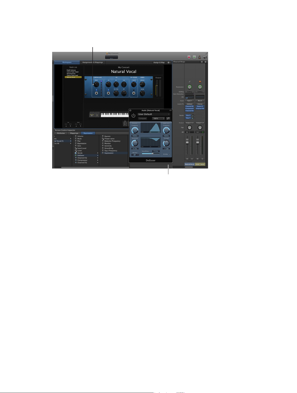
4 To map the screen control to a plug-in parameter, double-click the plug-in in the Inserts section
Click the screen control you
of the channel strip to open the plug-in window, then click the parameter in the plug-in window.
want to map to a parameter.
Click the parameter in a channel
strip or plug-in window.
The screen control is mapped to the selected parameter, and the Unmapped tab takes the name
of the parameter. You can continue mapping additional screen controls by clicking them in the
workspace and then clicking the corresponding parameters in a channel strip or plug-in window.
5 When you are nished, press Command-L again (or click the Map Parameter button) to turn
o mapping.
Map a screen control using the Parameter Mapping browser
1 In the workspace, click the screen control you want to map.
The screen control is highlighted in blue. The Screen Control Inspector appears below the
workspace, showing the parameters for the selected screen control. The Screen Control Inspector
includes General and Mapping tabs as well as a tab labeled “Unmapped.”
2 In the Screen Control Inspector, click the Unmapped tab.
The Parameter Mapping browser appears, showing the channel strips and plug-ins available for
mapping as well as the Actions folder.
3 In the column on the left of the Parameter Mapping browser, select the channel strip with the
parameter to which you want to map the screen control.
Parameters for the selected channel strip appear in the columns on the right. Additional folders
for the instruments and eects in the channel strip may appear in these columns. Click a folder
to see the parameters for that instrument or eect.
Chapter 5 Work in Edit mode 70
Page 71

4 Select the parameter you want to map.
Click the channel strip or
plug-in with the parameter
you want to map.
The screen control is mapped to the selected parameter, and the Unmapped tab takes the
name of the parameter. You can continue mapping additional screen controls by clicking them
in the workspace and then choosing parameters in the Parameter Mapping browser. Using the
Parameter Mapping browser, you can map parameters that are not visible in plug-in windows.
You can also map screen controls to MainStage actions and to AppleScript scripts. For more
information about mapping screen controls, see Map screen controls on page 69.
Click the parameter to which
you want to map the screen
control.
Note: If you change the channel strip setting for a channel strip to which you have mapped
screen controls, you will lose any parameter mappings.
You can also edit velocity sensitivity for a channel strip, create controller transforms, and
lter various MIDI messages. For information about editing channel strips, see Channel Strip
Inspector on page 48.
Map screen controls to actions
In addition to mapping screen controls to channel strip and plug-in parameters, you can map
them to MainStage actions. Actions let you select patches and sets; silence MIDI notes; control
the Tuner and the metronome; tap a new tempo; display information about patches, MIDI
messages, and other information; and perform other functions using screen controls.
For a complete table of actions, including descriptions and usage notes, see Actions overview on
page 156 .
The Actions folder, which appears in the Parameter Mapping browser along with available
parameters, contains actions for selecting patches and sets, showing the Tuner, activating tap
tempo, Master Mute, Panic, and other functions. The Actions folder also contains an AppleScript
subfolder with useful scripts.
You can map button screen controls to actions for selecting dierent patches and use physical
buttons on your MIDI device to select patches when you perform. You can also map buttons
to actions for selecting dierent sets or selecting the concert. For information about assigning
buttons, see Button assignments on page 112 .
Chapter 5 Work in Edit mode 71
Page 72

Map a screen control to an action
Click the Actions folder to see
1 In the workspace, click the screen control you want to map.
The Screen Control Inspector appears below the workspace, showing the settings for the
selected screen control. If the screen control is currently mapped, a tab with the name of the
mapping is visible in addition to the General and Mapping tabs. If the control is unmapped, the
tab is labeled “Unmapped.”
2 Click the Unmapped (or name of mapping) tab.
The Parameter Mapping browser appears below the workspace. The Actions folder is available in
the Parameter Mapping browser.
3 In the column on the left of the Parameter Mapping browser, click the Actions folder.
The available actions appear in the second column of the browser.
available actions.
Click the action you want to
map from the submenu.
4 Select the action you want to map.
Note: If you map a knob screen control to an action to select a patch (such as the −10 Patches,
Previous Patch, Next Patch, or +10 Patches action), the screen control jumps to the value of the
hardware control, regardless of the setting of the Respond to Hardware Move parameter in the
Screen Control Inspector.
Chapter 5 Work in Edit mode 72
Page 73

Map a screen control to multiple parameters
You can map a single screen control to multiple parameters and control how the screen control
modies each mapped parameter. Mapping a screen control to multiple parameters is also
referred to as multimapping. You map a screen control to up to eight parameters by adding
mappings in the Screen Control Inspector.
If you create multiple mappings for a screen control, you can dene the relationships between
the rst mapping and subsequent mappings. This can be especially useful when, for example,
you are mapping the same control to lter cuto and lter resonance, and you want to ensure
that resonance does not exceed a certain maximum value as you increase the cuto value. The
default relationship aects all future mappings (for the same and other screen controls), but does
not aect existing mappings. The default is set to Scale the rst time you open MainStage.
Add a mapping
1 Map the screen control to a parameter or action, as described in Map screen controls to channel
strip and plug-in parameters on page 69 and Map screen controls to actions on page 71.
2 With the screen control selected, click the Add Mapping (+) button at the upper-right corner of
the Screen Control Inspector.
A new Unmapped tab appears in the Inspector, showing the Parameter Mapping browser.
3 In the Parameter Mapping browser, choose the parameter to which you want to map the
screen control.
If you add a mapping while the Learn process is active (the Assign & Map button is red), you can
immediately learn the new mapping. There are key commands for selecting the previous and
next tab to make mapping to multiple parameters easier. For more information, see Parameter
mapping (Edit mode) on page 153.
View all mappings for a screen control
m In the Screen Control Inspector, click the Mappings tab.
The mappings appear in a list view that shows the minimum and maximum range values and
patch change behavior for each mapping and includes buttons to open the Parameter graph
and Invert graph values for each mapping.
Dene the default relationship between the rst mapping and subsequent mappings
1 Select a screen control you want to map to multiple parameters.
2 Choose Default Relation to First Mapping from the Action pop-up menu, located in the upper-
right corner of the Screen Control Inspector.
3 Do one of the following:
•
To set subsequent mappings to be oset by a xed value from the rst mapping: Choose Oset.
•
To set subsequent mappings to scale by a constant ratio, starting from the same minimum value:
Choose Scale.
•
To set subsequent mappings to scale by a constant ratio to the point dened for the mapping,
starting from both the same minimum value and maximum value: Choose Pivot.
Chapter 5 Work in Edit mode 73
Page 74

Edit the saved value for a mapped parameter
Each mapped parameter has a saved value. If you set the Parameter Values: On Patch Change
pop-up menu to “Reset to saved value” in MainStage General preferences or in the Attributes tab
of the Screen Control Inspector, the parameter value for a patch returns to the last saved value
when you change patches.
You can view and edit the saved value for each parameter mapping in the Screen Control
Inspector. If you change the value of a parameter in performance by manipulating screen
controls, those changes are saved only for the selected patch. Editing the saved value in the
Screen Control Inspector ensures that the value is saved, regardless of whether the patch is
selected.
To have MainStage reset patch parameters each time you select a patch, choose “Reset to saved
value” from the On Patch Change pop-up menu. You can edit the saved values directly in the
Screen Control Inspector, or by manipulating screen controls in a patch, then saving the concert
with the patch selected. This behavior is similar to a hardware synthesizer or eects unit.
To have MainStage save all changes to all patches when saving the concert, choose 'Keep current
value' from the On Patch Change pop-up menu. With this setting, when you save the concert, all
edits made to all patches are saved in the concert. This behavior is similar to many documentbased computer applications.
Edit the saved value for a parameter
1 In the Screen Control Inspector, click the tab for the mapping.
The current saved value for the parameter appears in the Saved Value value slider.
2 To edit the saved value, do one of the following:
•
Change the value in the Saved Value value slider.
•
Drag the slider to the right of the value slider left or right.
Note: When you save a concert, the current value of each screen control in the currently selected
patch is saved in the concert. You can see the values update in the Screen Control Inspector.
When you export a patch, the current parameter values become the saved values in the
exported patch.
Set drum pads or buttons to use note velocity
When you map a drum pad or button to a non-binary parameter (for example, to Volume
or Expression), you can set the screen control to use note velocity. This can make help make
performing with these controls more dynamic and expressive.
Set a drum pad or button screen control to use note velocity
1 Map the screen control to a non-binary parameter, such as Volume.
2 In the Screen Control Inspector, click the tab for the mapping.
3 Select the “Use note velocity” checkbox.
Chapter 5 Work in Edit mode 74
Page 75

Use parameter mapping graphs
Each parameter mapping has a Parameter graph. You can edit the graph to remap input values
to dierent output values for the parameter.
Open the Parameter graph for a mapping
m In the tab for the mapping or in the Mappings tab, double-click the Graph button for the
mapping you want to edit.
The Parameter graph window opens. The title of the graph window shows the parameter name.
For information about editing graphs, see Work with graphs on page 62.
Map screen controls to all channel strips in a patch
When you map a screen control to a channel strip parameter such as volume or pan, you can
map it to control the same parameter in all of the channel strips in the patch. This is particularly
useful when you want to control the overall volume of a layered sound, even if the dierent
layers are played across multiple keyboards.
Map a screen control to all channel strips in a patch
1 Map the screen control to a common screen control parameter, such as volume or pan.
2 In the column on the left of the Parameter Mapping browser, select the Send to All folder.
3 Select the destination from the second column.
4 Select the parameter to map the screen control to from the third column.
You can map the screen control to actions for transposing software instrument channel strips,
channel strip parameters, and MIDI control message types from the Destinations folder. When
you map a screen control to all channel strips in a patch, the parameter to which the screen
control is mapped changes to the same value for all channel strips in the patch when you move
the screen control.
Note: When you map a drum map using Send to All, the Send to All folder contains MIDI notes,
not controllers.
Undo screen control parameter mappings
You can undo parameter mapping if you decide you do not want to keep the mapping. When
you undo parameter mapping, all mappings created in the current Learn mode (either by
pressing Command-L or clicking the Map Parameter button) session are undone.
Undo parameter mappings
m Choose Edit > Undo (or press Command-Z).
Remove screen control mappings
If you want a screen control to be free of any mappings, you can remove its existing mapping.
This can be useful with controls that pass through MIDI messages (for example, for pitch bend
and modulation wheels, or expression pedals) when you do not want them to send MIDI
messages for their pass-through control type. You do not need to remove the mapping for a
screen control when you remap it.
Reset the mapping for a screen control
1 In the workspace, click the screen control you want to map.
2 In the column on the left of the Parameter Mapping browser, click None.
Chapter 5 Work in Edit mode 75
Page 76

Work in the Assignments and Mappings tab
Assignments and mappings overview
You can view and edit assignments and mappings for the selected patch, set, or concert in the
Assignments & Mappings table, and create and edit assignments and mappings without leaving
Edit mode.
For the selected item, the Assignments & Mappings table shows the following:
•
Assignment column: Lists the assignments in the patch, set, or concert by device and MIDI
channel.
•
Screen Control column: Shows the screen control to which each hardware control is assigned.
•
Mapping column: Shows the mapping for each control, following the same order as the Screen
Control Inspector.
You can quickly see whether a hardware control is assigned and see the parameter or action
to which it is mapped. When you manipulate a hardware control, a dot in the row showing its
assignment and mapping is highlighted.
The Assignments & Mappings tab also includes an Action pop-up menu, with items for creating
assignments and for selecting a mapping row when it receives MIDI input.
Show the Assignments and Mappings table
m Click the Assignments & Mappings tab at the top of the workspace (or press Command-Shift-M).
Click the Workspace tab at the top of the window (or press Command-Shift-W) to return to
the workspace.
Chapter 5 Work in Edit mode 76
Page 77

Create and delete assignments and mappings
The Assignments & Mappings tab includes an Assign & Map button so you can quickly create
new assignments and mappings. You can also create assignments and mappings independent of
any screen control, allowing you to use a hardware control to adjust the value of a parameter or
action for which there is no screen control in the workspace.
You can also delete assignments and mappings in the Assignments & Mappings table. When you
select a row in the table with both an assignment and a mapping, only the mapping is deleted.
When you select a row containing only an assignment, an alert appears. If the assignment has
a screen control, the assignment is deleted but the screen control remains in the table. If the
assignment has no screen control, the entire row is deleted.
Create a new assignment and mapping together
1 Choose New Assignment from the Action pop-up menu.
A new, blank row appears in the table.
2 Click the Assign & Map button.
3 Manipulate the hardware control you want to assign.
The row is updated to show the new assignment.
4 To create a mapping, do one of the following:
•
Select a mapping parameter or action in the Screen Control Inspector.
•
Click a parameter on a channel strip or a plug-in window.
The table is updated to show the new mapping.
Delete an assignment
1 In the table, select the row with the assignment, then press the Delete key.
2 In the alert that appears, click Delete.
Delete a mapping
m In the table, select the row with the mapping, then press the Delete key.
Chapter 5 Work in Edit mode 77
Page 78

Edit assignments and mappings
Using the Assign & Map button, you can also edit existing assignments and mappings in the
Assignments & Mappings table.
Edit an existing assignment or mapping
1 In the Assignments & Mappings table, select the assignment you want to edit.
2 Click the Assign & Map button.
3 To change the assignment, manipulate the hardware control you want to assign.
The table is updated to show the new assignment.
4 To change the mapping, do one of the following:
•
Select a new mapping parameter or action in the Screen Control Inspector.
•
Click a parameter on a channel strip or a plug-in window.
The table is updated to show the new mapping.
Edit Hardware Input parameters
You can view and edit the Hardware Input parameters for an assignment in the Assignments
& Mappings table, allowing you to quickly modify the assignment without leaving Edit mode.
For detailed information about particular Hardware Input parameters, see Screen controls
overview on page 102.
Edit Hardware Input parameters for an assignment
1 Click the assignment you want to edit.
2 In the dialog that appears, choose new Hardware Input parameters for the assignment from the
pop-up menus.
3 When you are nished, click Done, or click anywhere outside the dialog.
Block incoming controller messages
You can block incoming controller messages that you do not want MainStage to process. To
block incoming controller messages, the controller must not be assigned to any screen control.
Block unassigned controller messages
1 In the Assignments & Mappings table, select the text “Unassigned” in the Assignment column.
2 In the Screen Control Inspector, deselect the Send all unassigned MIDI to Channel
Strips checkbox.
Chapter 5 Work in Edit mode 78
Page 79

Edit screen control parameters in Edit mode
Screen control parameters in Edit mode overview
In Layout mode, you edit basic screen control parameters that are constant throughout the
entire concert. In Edit mode, you can edit screen control parameters for a specic patch or set,
including editing parameter labels, choosing custom colors, and changing the appearance of the
background or grouped screen control.
You can also override concert- and set-level mappings for an individual patch or a set.
Replace parameter labels
You can replace the parameter label for a screen control (for an individual patch or a set) to make
the label easier to identify.
Replace the parameter label for a screen control
1 Select the screen control in the workspace.
2 In the Screen Control Inspector, select the Attributes tab, then select the Replace Parameter Label
checkbox (or press Option-Control-L).
3 Enter the new label text in the eld.
Choose custom colors for screen controls
You can change the color of the active area of a screen control (for an individual patch or a set)
and also change the color of the text for a screen control.
Choose a custom color for a screen control
1 Select the screen control in the workspace.
2 In the Screen Control Inspector, click the Attributes tab.
3 Select the Custom Color checkbox, then choose a new color from the Custom Color
pop-up menu.
4 Select the Custom Label Color checkbox, then choose a new color from the Custom Label
Color menu.
Change the appearance of a background or grouped screen control
You can change the appearance of a background screen control or grouped set of screen
controls by choosing a dierent panel or adding a custom image.
Change the panel for a background or grouped screen control
1 In Edit mode, Option-click the screen control in the workspace.
2 In the Screen Control Inspector, make sure that the Custom Background checkbox is selected.
3 Click the Panel button.
4 Click the Panel well and choose a new panel from the pop-up menu.
Add a custom image for a background or grouped screen control
1 In Edit mode, Option-click the screen control in the workspace.
2 In the Screen Control Inspector, make sure that the Custom Background checkbox is selected.
3 Click the Image button, then click Select.
4 In the dialog that appears, browse to the image you want to use, select the image, then click
Choose Image.
Chapter 5 Work in Edit mode 79
Page 80

Set screen controls to show the hardware value
By default, screen controls show the value of the parameter the control is mapped to. In some
cases, for example, when the screen control is assigned to a foot pedal or when the screen
control is mapped to multiple parameters, it may be better to show the value of the hardware
control assigned to the screen control.
Set a screen control to show the hardware value
1 Select the screen control in the workspace.
2 In the Screen Control Inspector, click the Attributes tab.
3 Select the Show Input Value checkbox.
Set parameter change behavior for screen controls
You can set the behavior for saving parameter values for screen controls in individual patches.
This is useful, for example, when the default for saving parameter values is set to Reset, but you
want certain screen controls (for example, concert- and set-level screen controls) to keep their
current value when switching patches.
Set the behavior for saving parameter values in a patch
1 Select the patch.
2 Select the screen control for which you want to set the parameter change behavior.
3 In the Attributes tab of the Screen Control Inspector, choose the parameter change behavior for
the screen control from the “When a patch is changed and screen value diers from saved patch”
pop-up menu:
•
To have the screen control use the default behavior set in MainStage preferences:
Choose Preference.
•
To preserve changes to parameter values when you change patches: Choose Keep.
•
To return values to the last saved value: Choose Reset. When this value is chosen, you should
save the concert after making any changes you wish to keep to the patch, before selecting
another patch.
•
To have the screen control use the last received value from the physical control assigned to it:
Choose Match.
When you choose an item from the pop-up menu, a brief description of its function appears
below the menu.
Important: If you set the behavior for saving parameter values in a patch to Reset, parameter
values are also reset when you switch to Layout mode.
Chapter 5 Work in Edit mode 80
Page 81

Set hardware matching behavior for screen controls
Some hardware synthesizers and music workstations let users control what happens when
you move a physical control that is set to a dierent value than the parameter it modies. The
parameter value can instantly change to the position of the physical control (sometimes called
jump), it can change by the same amount (called relative), or it can not change at all until the
physical control matches its current value (called snap).
You can set the behavior for screen controls in MainStage to any of these behaviors when you
move the physical control assigned to the screen control.
Set the behavior for screen controls when you move a hardware control
1 Select the patch.
2 Select the screen control for which you want to set the hardware matching behavior.
3 In the Attributes tab of the Screen Control Inspector, choose the parameter change behavior for
the screen control from the “When hardware value diers from screen value” pop-up menu:
•
To have the screen control use the default behavior set in MainStage preferences:
Choose Preference.
•
To have the screen control instantly change to match the hardware value: Choose Jump.
•
To have the screen control change when the hardware control matches its current value:
Choose Pickup.
•
To have the screen control move relative to the hardware control: Choose Relative.
Note: When you choose an item from the menu, a brief description of its function appears below
the pop-up menu.
Reset and compare changes to a patch
You can reset changes to all parameters in a patch that are mapped to screen controls to their
last saved value, letting you hear the patch in its last saved (original) state, and toggle between
the original and modied states of the patch.
Reset and compare changes using the Reset/Compare action
1 In Layout mode, add a button screen control to your layout.
2 Assign a button on your hardware controller to the new button screen control.
3 In Edit mode, click the concert icon in the Patch List.
4 Select the new button screen control in the workspace.
5 In the Parameter Mapping browser, select the Actions folder, and then select the Reset/ Compare
Patch action in the second column.
For more information about mapping a screen control at the concert level, see Control the
overall volume of a concert on page 95.
Chapter 5 Work in Edit mode 81
Page 82

Override concert- and set-level mappings
Select the checkbox to
By default, mappings you make at the concert level (to parameters and actions) take
precedence over mappings to individual patches or sets in the concert. If you map a screen
control to a parameter at the concert level (for example, to Master Volume), that screen
control cannot be mapped to a parameter or action in a patch or set unless you override the
concert-level mapping.
Similarly, mappings you make at the set level take precedence over mappings for any patches in
the set. If you map a screen control to a parameter at the set level (for example, to an eect on
a set-level channel strip), that screen control cannot be mapped to a parameter or action in a
patch in the set unless you override the set-level mapping.
If you try to map a screen control that is mapped at the concert or set level, text appears in the
Screen Control Inspector informing you that the screen control is mapped at another level, and
the parameters in the Screen Control Inspector are dimmed. You can override the concert- and
set-level mappings for an individual patch, and then map the screen control at the patch level.
Override concert-level mappings
m In the Screen Control Inspector, select the Override Concert Mapping checkbox.
override mappings at the
concert level.
The parameters in the Screen Control Inspector become active.
Override set-level mappings and other parameters for a patch
m In the Screen Control Inspector, select the Override Set Mapping checkbox.
The Parameter Mapping section becomes active so that you can map the parameter.
Mapping tabs for concert-level mappings are available only at the concert level, and mapping
tabs for set-level mappings are available only at the set level. When you override a concert- or
set-level mapping, the mapping tabs become available at the level of the override.
Chapter 5 Work in Edit mode 82
Page 83

Work with sets in Edit mode
Work with sets overview
Sets are like folders that let you organize patches you want to keep together. Using sets, you can
organize patches in any manner. For example, you can put all the patches you want to use in the
rst part of a performance together or keep all your lead synth patches together. Sets are exible,
so you can use them in whatever way suits your method of working.
Here are some dierent ways you can use sets:
•
To group similar or related sounds into “banks”
•
To keep multiple patches you will use in a single song together
•
To share a set-level instrument or channel strip between a group of songs
Create sets
You can create a new, empty set or create a set from a group of selected patches.
Create a new, empty set
m Choose New Set from the Action pop-up menu in the upper-right corner of the Patch List.
A new set appears in the Patch List.
Create a set from a group of patches
1 In the Patch List, select the patches you want to include in the new set.
2 Choose New Set From Selection from the Action pop-up menu at the upper-right corner of the
Patch List.
The new set appears in the Patch List containing the selected patches. You can add new patches
to the set or drag existing patches into the set.
Rename sets
When you create a set, it is given a default name. You can rename a set in the same way you
rename a patch in the Patch List.
Rename a set
1 Double-click the set in the Patch List.
A text eld appears with the set name, which is selected.
2 Type a new name in the set name eld.
Set the time signature for sets
You can set the time signature for a set. Time signatures can be used with the Playback plug-in
and also aect the beats of the metronome. When you set the time signature for a set, it
overrides the concert-level time signature (if one is set).
Set the time signature for a set
1 In the Set Inspector, select the Has Time Signature checkbox.
2 Double-click the number in the eld, and enter the number of beats for the time signature.
3 Choose the beat value from the pop-up menu at the right.
Chapter 5 Work in Edit mode 83
Page 84

Change the tempo when you select a set
You can give a set its own tempo setting so that when you select the set, the tempo changes to
the set tempo setting. MainStage uses the new tempo until you select another patch or set with
its own tempo setting, tap a new tempo, or until MainStage receives tempo information from
incoming MIDI messages. For more information about using and changing tempo in MainStage,
see Tempo overview on page 90.
Change the tempo using a set
1 In the Patch List, select the set.
2 To activate the set tempo when the set is selected, select the “Change Tempo to” checkbox.
3 In the Set Inspector, set the set tempo using the “Change Tempo to” value slider.
Change the tuning for sets
By default, new sets (and most existing ones) use the same tuning method as the concert. You
can change the tuning for a set so that it uses a dierent tuning. When you change the tuning
method for a set, the patches in the set use the set-level tuning unless you change the tuning at
the patch level.
Change the tuning for a set
1 In the Set Inspector, click the Tuning tab.
2 Choose the tuning you want the set to use from the Method pop-up menu.
Collapse sets in the Patch List
You can collapse sets in the Patch List. When you collapse a set, you can select the set and use
any channel strips or busses at the set level but cannot select or play patches in the set while in
Edit mode.
Collapse a set
m In the Patch List, click the disclosure triangle for the set.
You can uncollapse the set by clicking its disclosure triangle again. Collapsing a set has no eect
on whether you can select patches in the set in Perform mode.
For information about creating and using sets, see Work with sets overview on page 83.
Override concert-level key ranges for a set
If a software instrument channel strip exists at the concert level, the concert-level channel strip
takes precedence over any set-level software instrument channel strips within its key range. This
means that when you play any notes in the key range of the concert-level channel strip on a
keyboard controller, you hear only the concert-level channel strip, even when a patch is selected
in a set with a set-level channel strip.
You can override the concert-level channel strip for a channel strip at the set level so that the
set-level channel strip takes precedence over the concert-level one.
Override concert- or set-level key ranges
1 In the Patch List, select the set with the channel strip that you want to override the concert-level
channel strip.
2 In the Channel Strips area, select the channel strip with the key range that you want to override
the concert-level key range.
3 Select the “Override parent ranges” checkbox.
Chapter 5 Work in Edit mode 84
Page 85

Delete sets
You can delete a set if you decide you no longer want it in the concert.
Delete a set
1 Select the set in the Patch List.
2 Choose Edit > Delete (or press the Delete key).
When you delete a set, the patches in the set are also deleted. To delete the set without deleting
the patches, move the patches outside the set before you delete it.
Add a channel strip at the set level
You can add channel strips at the set level and play the set-level channel strips together
with every patch in the set. This can be useful, for example, if you want to use the same bass
instrument in a single song or group of songs. You can place the patches for all of the songs in a
set, add a channel strip at the set level, and then add a bass instrument to the set-level channel
strip. You can set the key range of the bass instrument to play only notes in the lower octaves so
that you can play it together with your patches.
Important: If you add a channel strip at the set level, it takes precedence over all of the channel
strips in all of the patches in the set. For example, if you add a software instrument channel strip
at the set level, the software instrument for the set takes precedence over all of the software
instruments in all of the patches in the set that fall within the same key range as the set-wide
software instrument.
Add a set-level channel strip
1 In the Patch List, select the set.
2 Click the Add Channel Strip button (+) at the top of the Channel Strips area.
3 In the New Channel Strip dialog, select the type of channel strip you want to create.
4 Choose the audio output for the channel strip from the Output pop-up menu.
5 For audio channel strips, choose mono or stereo format from the Format pop-up menu and
choose the audio input from the Input pop-up menu.
6 Click Create.
Chapter 5 Work in Edit mode 85
Page 86

Share patches and sets between concerts
You can export patches and sets from a concert and import them into another concert. When
you import a set, all the patches in the set are imported.
Export a patch
Do one of the following:
m Drag the patch from the Patch List to the Finder.
The patch appears as a .patch le in the Finder.
m Select the patch, choose Save as Patch from the Action pop-up menu in the Patch List, then
click Save.
The patch is exported to the ~/Music/Patches folder.
Export a set
Do one of the following:
m Drag the set from the Patch List to the Finder.
The set appears as a .patch le in the Finder.
m Select the set, choose Save as Set from the Action pop-up menu in the Patch List, then click Save.
The set is exported to the MainStage Patches folder.
Note: You can also export an entire concert as a set by selecting the concert and choosing
Export Set from the Action pop-up menu.
You can export multiple patches or sets. When you export multiple patches by dragging them to
the Finder, each patch is exported as a .patch le. When you select multiple patches and export
them using the Export Patch command, the patches are grouped into a single exported set. You
can import patches or sets from the Finder to another open concert.
Import a patch or set
Do one of the following:
m In Edit mode, drag the patch or set from the Finder to the Patch List.
m Choose Load Patch/Set from the Action pop-up menu in the Patch List, select the patch or set
you want to import, then click Import.
Record the audio output of a concert
You can record the audio output of a MainStage concert. When you record audio output, all
audio on the output you choose is recorded (including the metronome, and so on).
Before you record audio output, make sure the correct output, recording location, and le format
are set in the Audio tab of MainStage preferences. For information about setting recording
preferences, see Audio preferences on page 149.
Record audio in Edit mode
m Click the Record button in the toolbar.
To stop recording, click the Record button again.
You can also map a screen control to the Record action to record audio in Perform mode and
assign a key command to the action to turn recording on or o using a hardware control.
Chapter 5 Work in Edit mode 86
Page 87

Work with concerts
6
Open and close concerts
You can create a new concert from a template, open an existing concert to continue working,
and close and save concerts. You can add patches to a concert and organize them in the
Patch List. The number of patches is limited only by the amount of available memory. You can
add channel strips to an existing patch or to new ones you create and can organize patches into
sets. For information about patches and sets, see Edit mode overview on page 37.
The process of creating a new concert from a concert template is described in Choose a
template on page 27. You can open an existing concert to play the patches in the concert or
continue editing them.
Open an existing concert
Do one of the following:
m Choose File > Open Concert, select the concert you want to open, then click Open.
m Choose File > New. In the Choose Template dialog, click Open an Existing Concert, then choose
the concert in the Open dialog.
m In the Finder, double-click the concert.
m In the Finder, drag the concert over the MainStage icon in the Dock.
The rst time you open a concert, the rst patch is selected, and the Patch Library is open so you
can easily choose a patch setting. When you reopen a concert, the patch that was selected when
you last saved the concert is selected.
If any audio les or other assets are not found when you open a concert, a dialog appears
showing which assets are missing, and asking if you want to search for the assets, locate them
manually, or skip them.
By default, when you open a concert, it opens in Edit mode. You can change the default behavior
in MainStage preferences. For more information, see General preferences on page 148.
Note: When you open a concert created with an earlier version of MainStage, it opens as an
untitled concert, and MainStage prompts you to save the concert as a MainStage 2 concert.
Reopen a recently open concert
Do one of the following:
m Choose File > Open Recent Concert, then choose a concert from the submenu.
m Open the Choose Template dialog, click Recent Concert, then choose the concert you want
to open.
Close a concert
m Choose File > Close Concert.
If you have edited the concert since the last time you saved it, you are prompted to save your
changes.
87
Page 88

Save concerts
When you save a concert, changes to mapped parameter values are saved only for the selected
patch or set but not for other patches or sets.
Some patches or plug-ins may use assets such as audio les, virtual instruments, Ultrabeat
samples, and Space Designer impulse response les. You can save the assets used in a concert
with the concert, so they will be available if you copy or move the concert le.
Save a concert
1 Choose File > Save.
2 The rst time you save a concert, the Save dialog appears. Enter a name for the concert, and
browse to the location where you want to save it, then click Save.
You can save a copy of a concert with a new name by choosing File > Save Concert As.
Save a concert including its assets
1 Choose File > Save As.
2 In the Save As dialog, select the checkboxes for the asset types you want to save in the concert.
3 Click Save.
For information about how to set the behavior for saving parameter values for screen controls in
individual patches, see How saving aects parameter values on page 89 and Edit the saved value
for a mapped parameter on page 74.
Chapter 6 Work with concerts 88
Page 89

How saving aects parameter values
In MainStage preferences, you can set whether changes to mapped parameters are kept when
you change patches or are reset to their saved value. By default, when you select a patch, the
mapped parameters in the previously selected patch return to their saved value (as dened in
the Screen Control Inspector). When you save the concert, changes to mapped parameters for
the currently selected patch are saved (but mapped parameters for other patches retain their
saved value).
If you set the On Patch Change preference to “Keep current value,” when you select a patch, the
mapped parameters in the previously selected patch retain their current value. When you save
the concert, the changes are saved (and the previous saved values are lost).
If, however, you close the concert without saving, mapped parameters return to their previously
saved values when you reopen the concert.
If you decide not to keep your latest changes, you can revert a concert to its previously saved
state.
Revert a concert to its last saved state
m Choose File > Revert to Saved.
All the changes you have made since the last time you saved the concert are lost when you
revert the concert to its last saved state.
Set the default behavior for saved values
1 Choose MainStage > Preferences.
2 In the Parameter Values section of the General preferences pane, choose the default behavior
from the On Patch Change pop-up menu.
•
To preserve changes to parameter values when you change patches, choose “Keep current
value.”
•
To return parameters to their last-saved value when you change patches, choose “Revert to
saved value.”
You can also set the behavior for saving parameter values for screen controls in individual
patches. For information, see Set parameter change behavior for screen controls on page 80.
Chapter 6 Work with concerts 89
Page 90

Set the time signature for a concert
You can set the time signature for a concert. Time signatures can be used with the Playback
plug-in and also aect the operation of the metronome. When you set the time signature for a
patch or set, it overrides the concert-level time signature while the patch or set is selected. When
you select a patch or set without a time signature, it uses the concert time signature.
Set the time signature
1 In the Concert Inspector, select the Has Time Signature checkbox.
2 Double-click the number in the eld at the right, and enter the number of beats for one measure
of the time signature.
3 Choose the beat value from the pop-up menu at the right.
Use tempo in a MainStage concert
Tempo overview
Each concert has a tempo, which you can change in dierent ways while you are performing.
Some plug-ins available in MainStage, including delay and tremolo eects, synthesizer LFOs, and
the metronome, can require a specic tempo. You can set the initial tempo for a concert and
change the tempo by selecting a patch or a set with its own tempo setting. You can also change
the tempo in real time by tapping a new tempo or have MainStage receive tempo changes from
incoming MIDI messages.
When you open a MainStage concert, the tempo setting in the Concert Inspector is used until
you change the tempo by selecting a patch or set with its own tempo setting or by tapping a
tempo. When you change the tempo, MainStage uses the new tempo until you change it again
or until you close the concert.
You can set the tempo for a concert in the Concert Inspector, which appears in the lower-left
corner of the MainStage window when the concert icon is selected in the Patch List. By default,
the tempo for new concerts is set to 120 beats per minute (bpm).
Set the tempo for a concert
1 In the Patch List, select the concert icon.
2 In the Concert Inspector, set the tempo using the Tempo slider or value slider.
Set the tempo
by dragging the
Tempo slider or using
the value slider.
You can use patches and sets to change the tempo when you select the patch or set while
performing. For information about patch tempo settings, see Change the tempo when you select
a patch on page 40. For information about set-level tempo settings, see Change the tempo when
you select a set on page 84.
Chapter 6 Work with concerts 90
Page 91

Tap the tempo
MainStage includes a “tap tempo” feature that allows you to set the tempo in real time while you
perform.
Tap the tempo on your computer keyboard
m Press Control-T several times at the desired tempo.
You can also tap the tempo using a screen control mapped to the Tap Tempo action. For
information about mapping screen controls to actions, see Map screen controls to actions on
page 71.
Get the tempo from MIDI Input
You can also have MainStage receive tempo changes from incoming MIDI messages. When the
“Get tempo from MIDI input” checkbox is selected, MainStage listens to incoming MIDI clock
messages for tempo information. If it receives tempo information, the concert tempo changes to
the new tempo value.
Get the tempo from incoming MIDI clock messages
1 In the Concert Inspector, select the “Get tempo from MIDI input” checkbox.
2 Choose the MIDI clock source from the Device pop-up menu.
When the “Get tempo from MIDI input” checkbox is selected, the Tempo slider is dimmed and
cannot be edited. If MIDI messages MainStage receives do not include MIDI clock information,
MainStage uses the concert tempo setting and changes the tempo when you select a patch or
a set with its own tempo setting or tap a new tempo. If MainStage stops receiving MIDI clock
messages, it continues to use the last received value for the tempo until you select a patch or set
with its own tempo setting or tap a new tempo.
Chapter 6 Work with concerts 91
Page 92

Dene the source for program change messages
By default, MainStage receives and responds to program change messages from all connected
MIDI controllers. Some MIDI controllers, however, send program change messages while
performing other operations. You can dene the source for program change messages for a
concert, so the concert responds to messages for only one MIDI device, port, or channel.
Choose the source for program change messages
1 In the Attributes tab of the Concert Inspector, choose the device or port from which the concert
will receive program change messages from the Device pop-up menu.
2 If you want to limit messages to a single MIDI channel on the device, choose the MIDI channel
from the Channel pop-up menu.
Set the pan law for a concert
Audio signals panned to the center position may sound louder than signals panned hard left or
right. The Pan Law value determines the amount of volume reduction applied to audio that is
panned to the center position. You can choose the pan law setting in the Attributes tab.
Set the pan law in the Concert Inspector
m In the Attributes tab of the Concert Inspector, choose one of the following pan law settings:
•
0 dB: With no change to the volume level, signals will seem louder when panned to the center
position, in comparison with extreme left or right pan positions.
•
−3 dB: A full scale signal (0 dBfs) will have a level of −3 dB when panned to the center position.
•
−3 dB compensated: A full scale signal (0 dBfs) will have a level of 0 dB when panned to the
center position (or +3 dB when panned to extreme left or right positions).
Change the tuning for a concert
By default, concerts use equal tempered tuning. You can change the tuning for a concert so that
it uses a dierent tuning.
Change the concert tuning
1 In the Concert Inspector, click the Tuning tab.
2 Choose the tuning you want the concert to use from the Method pop-up menu.
When you change the tuning of a concert, the tuning of the patches and sets in the concert
changes if their Tuning Method is set to “Use parent tuning.” Patches and sets with a dierent
tuning method are not aected.
Silence MIDI notes
MainStage also includes a Panic function. The Panic function immediately silences any hanging
MIDI notes.
Silence all MIDI notes
Do one of the following:
m Press Control-P.
m Double-click the MIDI Monitor in the toolbar.
m If you have mapped the Panic function to a screen control, press or move the
corresponding controller.
Chapter 6 Work with concerts 92
Page 93

Mute audio output
Sometimes when you are playing or editing sounds, you may want to quickly mute (silence) all
audio output for the concert. MainStage includes a Master Mute button that silences the output
from every patch in the concert.
Quickly mute all sound
Do one of the following:
m Press Control-M.
m In the toolbar, click the Master Mute button.
m If you have mapped the Master Mute function to a screen control, press or move the
corresponding controller.
The Master Mute button changes to show that the output is muted (a red diagonal line covers
the speaker icon). All output remains muted until you unmute it.
Unmute all sound
Do one of the following:
m Press Control-M again.
m In the toolbar, click the Master Mute button again.
m If you have mapped the Master Mute function to a screen control, press or move the
corresponding controller.
Master Mute is also a mappable parameter in the Parameter Mapping browser. You can map
Master Mute to a button or other controller in your concerts so that you can quickly mute all
output when you are playing live in Perform mode.
In addition, you can mute audio output for a single channel strip by clicking its Mute (M) button.
Chapter 6 Work with concerts 93
Page 94

Work at the concert level
Click the concert icon in the
Concert level overview
You can control the overall volume for a concert and make other changes at the concert level.
You can use busses at the concert level to control concert-wide eects or to control the output
of multiple channel strips assigned to the bus. You can also add channel strips at the concert
level and have the concert-level channel strips available with every patch in the concert.
You can map screen controls to busses and to concert-level channel strips only at the concert
level, not at the patch or set level.
Make changes at the concert level
m In Edit mode, click the concert icon in the Patch List.
Patch List to work at the
concert level.
Chapter 6 Work with concerts 94
Page 95

Control the overall volume of a concert
A MainStage concert contains Output and Master channel strips that you can use to control
the overall volume of the concert. The Master channel strip always controls the output volume
of the entire concert. If the concert has multiple Output channel strips, each Output channel
strip controls the volume level for a particular (mono or stereo) physical output. You can use the
Output and Master channel strips to control the overall volume of a concert.
To see all of the channel strips, you may need to resize the Channel Strips area.
At the concert level,
the Channel Strips
area shows the Output
and Master channel
strips, auxes, and other
concert-level channel
strips.
You can map a screen control to a channel strip parameter or an action at the concert level.
For example, you can map the Output 1-2 Volume fader to a fader screen control and use the
hardware control assigned to that screen control to adjust the overall volume of the concert.
Control the overall concert volume level
m Drag either the Output 1-2 volume fader or the Master volume fader.
Map a screen control at the concert level
1 Make sure the concert icon is selected in the Patch List.
2 Click the screen control you want to map.
3 In the Parameter Mapping browser, click the parameter to which you want to map the
screen control.
In the example above, you would click the fader screen control, click Out 1-2 in the left column of
the Parameter Mapping browser, and then click Volume in the second column of the browser.
Screen controls can also display visual feedback about parameter values, including volume level.
For example, you can also map the Output 1-2 Volume fader to a level meter screen control
and have the level meter display the overall volume level while you are performing live. In this
case, you would map the level meter to Level in the second column of the browser, rather than
to Volume.
Chapter 6 Work with concerts 95
Page 96

When you map a screen control at the concert level, you cannot map the same screen control
Choose a bus from one of the
at the patch or set level unless you override the concert-level mapping. For information about
overriding concert-level mappings, see Override concert- and set-level mappings on page 82.
Add concert-wide eects
You can add concert-wide eects such as reverb and delay using auxiliary (aux) channels. When
you choose a bus from the Send slot on a channel strip, a corresponding aux appears at the
concert level. You can insert eects on the aux and have those eects apply to every channel
strip sending its signal to the aux.
Send a channel strip signal to an aux
1 In the Patch List, select the patch you want to use with a concert-wide eect.
2 On the channel strip, click one of the Send slots and choose a bus from the pop-up menu.
Send slots.
3 Drag the Send knob next to the slot to set the amount of the signal sent to the aux.
Add a concert-wide eect to an aux
1 In the Patch List, click the concert icon.
The auxes in the concert appear in the Channel Strips area along with the concert-level
channel strips.
2 On an aux, click one of the Insert slots and choose an eect from the pop-up menu.
After you add an eect to an aux, you can edit the eect as you would any channel strip eect,
by clicking it to open the plug-in window and then adjusting parameters in the plug-in window.
You can add multiple eects to an aux, and adjust the level and pan of the aux using the channel
strip controls on the aux.
You can also add concert-wide eects to an aux at the patch level if Show Signal Flow Channel
Strips is turned on. For information about showing signal ow channel strips in the Channel
Strips area, see Show signal ow channel strips on page 46.
Chapter 6 Work with concerts 96
Page 97

Use auxes to control channel strip output
You can send the output of multiple channel strips to an aux (auxiliary channel strip) and then
use the aux to control the volume level and pan position of the channel strips. Sending the
output to an aux is also useful for adding EQ or compression to a group of patches.
When you send channel strip output to an aux, the volume fader of the channel strip controls
how much of the signal is sent to the aux.
When you control the output of multiple channel strips using an aux, their relative volume levels
and pan positions are preserved, but the overall volume level and pan position are modied by
the aux Volume fader and Pan knob.
Send the output of a channel strip to an aux
1 In the Patch List, select the patch you want to control using an aux.
2 In the channel strip, click the Output slot and choose a bus from the pop-up menu.
Control the output of channel strips using an aux
1 In the Patch List, click the concert icon.
The concert is selected. The busses added to the concert appear in the Channel Strips area along
with the concert-level channel strips.
2 Drag the Volume fader on the aux to adjust the volume level of the overall aux output.
3 Drag the Pan knob on the aux to adjust the pan position of the overall aux output.
Chapter 6 Work with concerts 97
Page 98

Add channel strips at the concert level
You can add a channel strip at the concert level and use the concert-level channel strip for a
software instrument or audio input you want to use in every patch in the concert.
Important: When you add a channel strip at the concert level, it takes precedence over the
channel strips in the patches and sets in the concert. For example, if you add a concert-level
channel strip containing a software instrument, the software instrument takes precedence over
all of the software instruments in all of the patches and sets in the concert, for the notes in its
key range. This means that you will hear only the sound of the concert-level software instrument
and will not be able to play any software instruments in a patch or set that fall in the same
key range.
Add a concert-level channel strip
1 In the Patch List, select the concert icon.
2 Click the Add Channel Strip button (+) at the top of the Channel Strips area.
3 In the New Channel Strip dialog, select the type of channel strip you want to create.
4 Choose the audio output for the channel strip from the Output pop-up menu.
5 For audio channel strips, choose mono or stereo format from the Format pop-up menu.
Important: Audio channel strips can produce feedback, particularly if you are using a
microphone for audio input. When you add an audio channel strip, the volume of the channel
strip is set to silence, and Feedback Protection is turned on to alert you when feedback occurs on
the channel strip. When you add an external instrument channel strip, the volume of the channel
strip is set to silence, but Feedback Protection is turned o.
6 Click Create.
7 For software instrument channel strips, you can dene the key range for the channel strip in
the Channel Strip Inspector so that the concert-level channel strip does not overlap software
instruments you plan to use in your patches and sets.
For information about dening the key range of a channel strip, see Layers and splits
overview on page 59.
When you add a channel strip at the concert level, you can map screen controls to the channel
strip only at the concert level, not for individual patches or sets.
Chapter 6 Work with concerts 98
Page 99

The MainStage clock
Some plug-ins, including the Playback and Ultrabeat plug-ins, require a time source, and use beat
and tempo information in order to play in time.
Additionally, some third-party applications and plug-ins using their own sequencer or playback
engine may behave dierently than the included plug-ins. These applications (which include
Reason and other ReWire applications, and Reaktor) require a play message from the host
application to begin playback and require a stop message to end playback. They may also
require a continue (also sometimes called “resume”) message to continue playback from their
current time position.
MainStage includes an internal beat clock or “time base” that you can use to control the playback
of these plug-ins. The MainStage clock generates beat, time position, and tempo information
so sequencer-oriented plug-ins can start, stop, and play in time. The MainStage clock operates
similarly to the song position in Logic Pro or other DAW applications.
You can send play and stop messages in the following ways:
•
Using the Play/Stop button in the toolbar, if it is visible
•
Using the Metronome button in the toolbar, if it is visible (turning on the metronome also
starts the MainStage clock, if it is not already running)
•
Using a screen control mapped to the Play/Stop, Play, or Stop action
•
Using a screen control mapped to the Continue action to resume playback of a third-party
plug-in (but not a Playback plug-in)
Dierent plug-ins can make use of the MainStage clock in dierent ways, depending on what
information they require and what mode they are set to. Some plug-ins may only make use of
the beat information, while others may only make use of tempo information. For example:
•
The Playback plug-in can start immediately (if Snap To is set to O), at the beginning of the
next bar (if Snap To is set to Bar), or at the next beat (if Snap To is set to Beat). It can also
start when you start the MainStage clock (if Start with Play Action is chosen from the Action
pop-up menu).
•
UltraBeat starts when you start the MainStage clock if its sequencer is turned on, except in
Pattern mode.
•
Reason and other ReWire applications start when you start the MainStage clock, and stop
when you stop the MainStage clock.
•
For plug-ins with synchronizable LFOs, the LFO can oscillate at the tempo set by the
MainStage clock (you can also send MIDI beat clock to synchronize external MIDI devices).
You can view the beat information of the MainStage clock using a Parameter Text screen control
mapped to the Beat Count action. When the MainStage clock is running, the current bar and
beat are displayed in the screen control.
Chapter 6 Work with concerts 99
Page 100

Important: When you start the MainStage clock, the audio engine is reset, causing a brief
interruption in the audio output from MainStage. In some cases, you may want to start the
MainStage clock at the beginning of a song or performance and use screen controls mapped
to individual plug-in parameters to start and stop those plug-ins to avoid an interruption in the
audio output while you are performing.
Control the metronome
MainStage features a metronome that you can use to play in time with the concert tempo. The
metronome always plays at the current tempo of the concert.
You can start the metronome in one of several ways, and change the audio output for the
metronome sound, the sound of the metronome, and the volume of the metronome relative to
the overall audio output.
Start the metronome
Do one of the following:
m Click the Metronome button in the toolbar.
m Click a button mapped to the Metronome action.
m If you are using a Playback plug-in, click the Metronome button in the Playback window (or click
a button mapped to the Metronome button).
Click any of the listed buttons again to stop the metronome.
Note: Starting the metronome also starts the MainStage clock if it is not already running.
By default, the metronome sound is routed to the main outputs (Output 1-2). You can route the
metronome to another output pair, which can be useful in performance when you want to hear
the metronome sound through a separate audio output (for example, a headphone mix) and not
through the main outputs. You can also choose a dierent sound for the metronome.
Change the audio output for the metronome sound
1 Choose MainStage > Preferences.
2 In the Metronome section of the General tab, choose a dierent audio output from the Output
pop-up menu.
Change the relative output of the metronome sound
1 Choose MainStage > Preferences.
2 In the Metronome section of the General tab, drag the volume slider left or right to adjust the
relative volume of the metronome sound.
Change the sound of the metronome
1 Choose Show Metronome Channel Strip from the Channel Strips Action pop-up menu.
2 Open the Klopfgeist plug-in from the Instrument menu on the Metronome channel strip.
3 Choose a dierent metronome sound.
Chapter 6 Work with concerts 100
 Loading...