

Page 1
K
Service Source
Macintosh LC 520/550/575
Macintosh LC 520, Macintosh LC 550,
Macintosh LC 575
Page 2
Service Source
Basics
Macintosh LC 520, 550, 575
Page 3
Basics Overview - 1
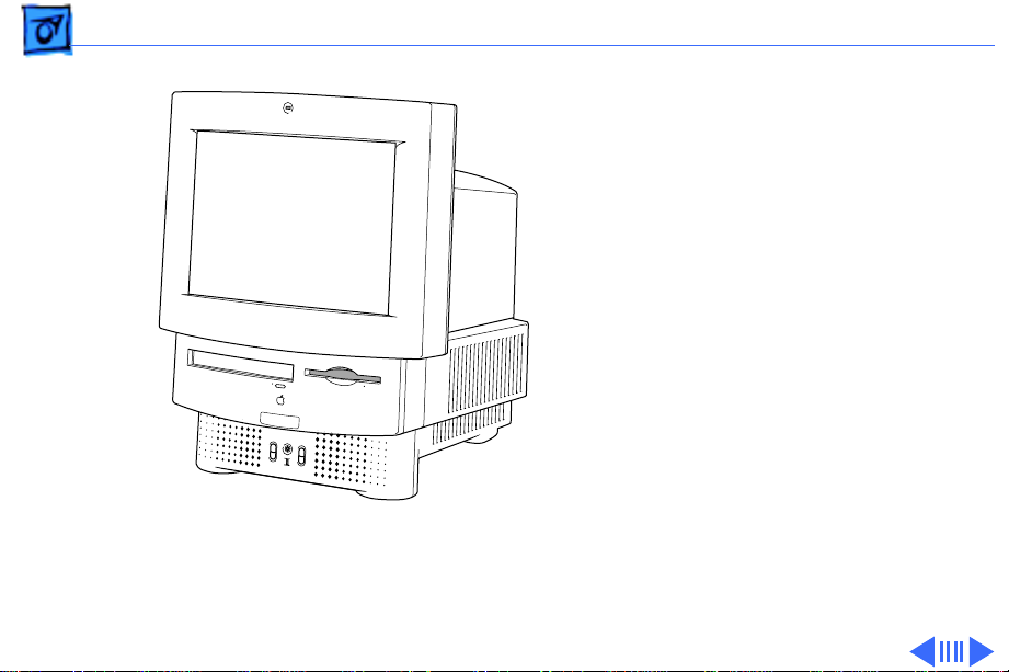
Overview
This manual includes
complete repair procedures
for the LC 520, LC 550, and
LC 575, shown at left.
Figure: Macintosh LC 520, LC 550, LC 575
Page 4

Basics Product Information - 2
Product Information
Identifying Features
The LC 575 logic board includes a 68LC040 processor, an
additional communications slot, and a new hook-and-loopattached battery. The LC 520 and LC 550 do not include these
features.
The LC 550 and LC 575 ship with
• the newer manual-inject 1.4 MB Apple SuperDrive and
require the keyhole-shaped bezel.
• a revised chassis harness assembly that does not use a
floppy drive adapter
• the newer, caddyless CD 300+ CD ROM drive
Page 5

Basics Product Information - 3
Compatibility Notes
You can exchange the chassis harness assembly of the LC
520 or LC 550 with the newer chassis harness assembly of
the LC 575. The newer chassis harness assembly requires
the manual-inject floppy drive and caddyless CD ROM drive.
Page 6
K
Service Source
Specifications
Macintosh LC 520, 550, 575
Page 7

Specifications Processor - 1
Processor
LC 520
LC 550
LC 575
Coprocessor
Motorola 68030 microprocessor
25 MHz
Built-in memory management unit (MMU)
Motorola 68030 microprocessor
33 MHz
Built-in MMU
Motorola 68LC040 microprocessor
33 MHz
Built-in MMU
Socket for optional math coprocessor
Page 8

Specifications Memory - 2
Memory
RAM
ROM
PRAM
4 MB of dynamic RAM on board
Expandable to 36 MB (100 ns or faster SIMMs)
72-pin DRAM SIMM connector
1 MB of ROM
256 bytes of clock/calendar/parameter memory
Long-life lithium battery
Page 9

Specifications Memory - 3
VRAM
512K of VRAM on board (displays up to 256 colors or 8-bit
color)
Expandable to I MB (displays up to 32,000 colors or 16-bit
color)
68-pin VRAM SIMM connector (LC 520)
Two VRAM SIMM slots (LC 575)
Page 10

Specifications Disk Storage - 4
Disk Storage
Floppy Drive
Hard Drive
CD-ROM Drive
Internal 1.4 MB Apple SuperDrive, auto-inject (LC 520)
Internal 1.4 MB Apple SuperDrive, manual-inject (LC 550 and
LC 575)
3.5-inch, internal 80, 160, 250, or 320 MB SCSI hard drive
Internal Apple CD 300i CD-ROM drive (LC 520)
Internal Apple CD 300+ CD-ROM drive (LC 550 and LC 575)
Page 11

Specifications I/O Interfaces - 5
I/O Interfaces
Serial
SCSI
Apple Desktop Bus
Processor-Direct Slot
Two RS-232/RS-422 serial ports; mini DIN-8 connectors
One SCSI parallel port; DB-25 connector
Connects up to six external SCSI devices
Two Apple Desktop Bus (ADB) ports; mini DIN-4 connectors
Maximum of three ADB devices recommended
Maximum current draw: 500 mA (Mouse draws 10 mA; keyboard
draws 25 mA.)
Internal expansion slot for 96 or 114-pin processor-direct
expansion cards
Page 12

Specifications I/O Interfaces - 6
Communications Slot (LC 575)
Sound
Internal expansion for 50-pin modem and Ethernet cards
Sound-output port capable of delivering stereo sound
Sound-input port for monaural sound input
Front headphone jack capable of delivering stereo sound
Page 13

Specifications I/O Devices - 7
I/O Devices
Keyboard
Mouse
Microphone
Speaker
Standard 80-key Apple keyboard with numeric keypad; ADB
connector
Soft power-on switch
2.5 mm travel, 18 mm vertical and horizontal pitch
Two-level tilt adjustment
Apple Desktop Bus Mouse II
New, ergonomic design
Built-in electret, omnidirectional microphone
Adjustable sound control on front of bezel
Page 14

Specifications Sound and Video - 8
Sound and Video
Sound Generator
Video Display
Records at 11 kHz or 22 kHz sample rate
Plays back at 22 kHz sample rate
Two speakers with enhanced stereo sound
Allows playback and recording of ordinary audio compact discs
14-in. diagonal, 13-in. viewable screen
Trinitron CRT with high-contrast glass
.26-mm aperture grille pitch
640 pixels by 480 lines; 70 dpi
Page 15

Specifications Electrical - 9
Electrical
Line V oltage
Frequency
Maximum Power
100–240 VAC; Universal power supply
47–63 Hz, single phase
120 W
Page 16

Specifications Physical - 10
Physical
Dimensions
Weight
Height: 17.9 in. (45.5 cm)
Width: 13.5 in. (34.4 cm)
Depth: 16.5 in. (42.0 cm)
40.5 lb. (18.4 kg)
Page 17

Specifications Environmental - 11
Environmental
Operating Temperature
Storage Temperature
Relative Humidity
Altitude
50–104° F (10–40° C)
-40 to 149° F (-40 to 65° C)
20–95% noncondensing
0–10,000 ft. (operating)
Page 18

K
Service Source
Troubleshooting
Macintosh LC 520, 550, 575
Page 19

Troubleshooting General/ - 1
General
The Symptom Charts included in this chapter will help you
diagnose specific symptoms related to your product. Because cures
are listed on the charts in the order of most likely solution, try
the first cure first. Verify whether or not the product continues to
exhibit the symptom. If the symptom persists, try the next cure.
(Note: If you have replaced a module, reinstall the original module
before you proceed to the next cure.)
If you are not sure what the problem is, or if the Symptom Charts
do not resolve the problem, refer to the Flowchart for the product
family.
For additional assistance, contact Apple Technical Support.
Page 20

Troubleshooting Symptom Charts/Video - 2
Symptom Charts
Video
Screen is black, too
dark, or too bright;
audio and drive
operate
Screen is bright and
audio is present, but
no video information
is visible
1 Adjust contrast button on front bezel.
2 Adjust brightness. Use Screen Control Panel.
3 Check yoke cable connection.
4 Perform video adjustments. Refer to “Video” in Adjustments
chapter.
5 Perform battery verification.
6 Replace analog board.
7 Replace CRT.
1 Perform video adjustments. Refer to “Video” in Adjustments
chapter.
2 Replace analog board.
3 Replace CRT.
Page 21

Troubleshooting Symptom Charts/Video
(Continued)
- 3
Single vertical or
horizontal line is
displayed
Predominant color
tint or color cannot be
adjusted
Black screen spots
(burnt phosphors)
Video
Note:
bottom third of a lit screen. This line is inherent in the design of
Trinitron monitors. Do not replace modules.
Otherwise,
1 Replace analog board.
2 Replace CRT.
1 Perform video adjustments. Refer to “Video” in Adjustments
2 Replace analog board.
3 Replace CRT if red, green, or blue cannot be turned off using
Replace CRT.
(Continued)
A thin, gray, horizontal line may be visible across the
chapter.
appropriate controls.
Page 22

Troubleshooting Symptom Charts/Video
(Continued)
- 4
Picture breaks into
diagonal lines, or
picture rolls
vertically or
horizontally
Out of convergence
(color bleeds from
text or lines)
Flashing or wavy
screen or monitor
emits high-pitched
noise
Video
1 Perform video adjustments. Refer to “Video” in Adjustments
2 Replace analog board.
1 Perform convergence adjustment. Refer to “Convergence” in
2 Replace analog board.
3 Replace CRT.
Replace analog board.
(Continued)
chapter.
Adjustments chapter.
Page 23

Troubleshooting Symptom Charts/Video
(Continued)
- 5
Video
Screen jitters or
flashes
Out of focus 1 Perform focus adjustment. Refer to “Focus” in Adjustments.
Raster size too short/
tall or narrow/wide
1 Verify that adjacent computer equipment is properly
2 Check that all ground cables are secure.
3 Disconnect internal floppy drive, CD-ROM drive, and hard
4 Replace analog board.
2 Replace analog board.
3 Replace CRT only if one part of display remains out of focus
1 Adjust horizontal or vertical size control. Refer to
2 Replace analog board.
(Continued)
grounded. Move electrical devices away from monitor.
Temporarily shut off all fluorescent lights in area.
drive.
despite adjustment of focus controls to their limits.
Adjustments chapter.
Page 24

Troubleshooting Symptom Charts/Video
(Continued)
- 6
Linearity bad (size of
text/graphics differs
at top, bottom, or
sides of screen)
Raster tilted or
shifted
Video
1 Perform video adjustments. Refer to “Video” in Adjustments
2 Replace analog board.
1 Verify that adjacent computer equipment is properly
2 Perform appropriate geometric adjustments. Refer to
3 Perform yoke adjustment. Refer to “Yoke” in Adjustments
4 Replace analog board.
(Continued)
chapter.
grounded. Move electrical devices away from monitor.
Temporarily shut off all fluorescent lights in area.
Adjustments chapter.
chapter.
Page 25

Troubleshooting Symptom Charts/Video
(Continued)
- 7
Video
Raster not centered 1 Verify that adjacent computer equipment is properly
2 Adjust horizontal or vertical center control. Refer to
3 Replace analog board.
Raster distorted
(barrel-shaped,
corners not square,
stretched or
compressed at top of
display, or sides not
perpendicular)
1 Verify that adjacent computer equipment is properly
2 Perform appropriate geometric adjustments. Refer to
3 Replace analog board.
4 Replace CRT (only in rare instances).
(Continued)
grounded. Move electrical devices away from monitor.
Temporarily shut off all fluorescent lights in area.
Adjustments chapter.
grounded. Move electrical devices away from monitor.
Temporarily shut off all fluorescent lights in area.
Adjustments chapter.
Page 26

Troubleshooting Symptom Charts/Floppy Drive - 8
Floppy Drive
Audio and video are
present, but internal
floppy drive does not
operate
Disk ejects; display
shows icon with
blinking “X”
1 Replace bad disk with known-good disk.
2 Replace floppy drive.
3 Replace logic board. Retain customer’s SIMMs.
4 Replace floppy drive.
5 Replace chassis harness cable.
1 Replace bad system disk with known-good system disk.
2 Replace floppy drive.
3 Replace logic board. Retain customer’s SIMMs.
4 Replace chassis harness cable.
Page 27

Troubleshooting Symptom Charts/Floppy Drive
(Continued)
- 9
Floppy Drive
Does not eject disk 1 Insert opened paper clip into hole beside floppy drive.
2 Switch off system and hold mouse button down while
switching system on (to complete eject cycle).
3 Remove front drive bezel.
4 Replace floppy drive.
Internal floppy drive
runs continuously
1 Replace bad disk with known-good disk.
2 Replace floppy drive.
3 Replace logic board. Retain customer’s SIMMs.
4 Replace floppy drive.
5 Replace chassis harness cable.
(Continued)
Page 28

Troubleshooting Symptom Charts/Floppy Drive
(Continued)
- 10
Unable to insert disk
all the way
Floppy Drive
1 To eject previously inserted disk, insert opened paper clip
into hole beside floppy drive.
2 Switch off system and hold mouse button down while
switching system on (to complete eject cycle).
3 Remove front drive bezel.
4 Replace floppy drive.
(Continued)
Page 29

Troubleshooting Symptom Charts/Hard Drive - 11
Hard Drive
Internal or external
hard drive does not
operate
Works with internal
or external SCSI
device but does not
work with both
1 Verify that SCSI loopback card is not attached.
2 Verify that external drive is properly terminated.
3 Replace hard drive.
4 Replace logic board. Retain customer’s SIMMs.
5 Replace hard drive.
6 Replace chassis harness cable.
1 Verify that SCSI device ID switch setting on external device
is higher than 0. Also verify that ID switch setting on
external SCSI device does not duplicate ID switch settings on
any other attached external SCSI devices.
2 Replace terminator on external SCSI device.
3 Replace SCSI select cable.
Page 30

Troubleshooting Symptom Charts/CD-ROM Drive - 12
CD-ROM Drive
CD-ROM drive does
not accept disc
Volume control does
not operate correctly
Macintosh cannot
mount CD-ROM drive
1 Replace disc (if dirty or damaged).
2 Remove front drive bezel.
3 Replace CD-ROM drive mechanism.
1 Reset PRAM.
2 Replace chassis harness assembly.
1 Verify proper CD-ROM software is installed.
2 Start up from known-good system, Disk Tools, or external
SCSI device.
3 Replace CD-ROM drive mechanism.
Page 31

Troubleshooting Symptom Charts/Peripheral - 13
Peripheral
Cursor does not move 1 Check mouse connection.
2 If mouse was connected to keyboard, connect it to rear ADB
port instead. If mouse works, replace keyboard.
3 If mouse does not work in any ADB port, replace mouse.
4 Reset PRAM.
5 Remove additional PDS and CS cards.
6 Replace logic board. Retain customer’s SIMMs.
Cursor moves, but
clicking mouse
button has no effect
1 Replace mouse.
2 Replace logic board. Retain customer’s SIMMs.
Page 32

Troubleshooting Symptom Charts/Peripheral
(Continued)
- 14
Cannot double-click
to open application,
disk, or server
No response to any
key on keyboard
Peripheral
1 Remove extra system files on hard drive.
2 Clear parameter RAM. Hold down <Command> <Option> <P>
<R> keys during system startup but before “Welcome to
Macintosh” appears.
3 If mouse was connected to keyboard, connect it to rear ADB
port instead. If mouse works, replace keyboard.
4 If mouse does not work in any ADB port, replace mouse.
5 Replace logic board. Retain customer’s SIMMs.
1 Check keyboard connection to ADB port.
2 Replace keyboard cable.
3 Replace keyboard.
4 Reset PRAM.
5 Replace logic board. Retain customer’s SIMMs.
(Continued)
Page 33

Troubleshooting Symptom Charts/Peripheral
(Continued)
- 15
Known-good
ImageWriter or
ImageWriter II does
not print
Known-good
LaserWriter does not
print
Peripheral
1 Make sure that Chooser and Control Panel are set correctly.
2 Replace printer driver and system software with known-
good.
3 Reset PRAM.
4 Replace printer interface cable.
5 Replace logic board. Retain customer’s SIMMs.
1 Make sure that Chooser and Control Panel are set correctly.
2 Replace printer driver and system software with known-
good.
3 Reset PRAM.
4 Refer to Networks and Communications manual.
(Continued)
Page 34

Troubleshooting Symptom Charts/Miscellaneous - 16
Miscellaneous
Clicking, chirping,
or thumping sound
Smoke/odor 1 Inspect analog board and logic board for any signs of burnt
No video, no audio, and
no drive operation
1 Replace analog board.
2 Replace logic board. Retain customer’s SIMMs.
components.
2 Replace analog board.
1 Connect power cord.
2 Switch power on.
3 Replace power cord.
4 Replace keyboard.
5 Replace analog board.
6 Replace logic board. Retain customer’s SIMMs.
Page 35

Troubleshooting Symptom Charts/Miscellaneous
(Continued)
- 17
Screen shows “Sad
Macintosh” icon and
black vertical lines;
screeching sound
Headphone jack does
not operate correctly
Speaker jacks do not
operate
System automatically
restarts after
shutdown
Miscellaneous
1 Replace RAM SIMMs on logic board.
2 Replace logic board. Retain customer’s SIMMs.
1 Verify that headphone jack is seated properly.
2 Replace chassis harness assembly.
1 Verify that speaker jacks are seated properly.
2 Replace logic board.
Check whether test jumper is installed on analog board (location:
BD 11). If it is installed, remove it.
(Continued)
Page 36

Troubleshooting Symptom Charts/Miscellaneous
(Continued)
- 18
Miscellaneous
“Sad Macintosh” icon 1 Replace bad disk with known-good disk.
2 Disconnect internal and external IDE or SCSI devices. If the
flashing “?” appears, re-attach devices one at a time.
Troubleshoot software issue on device that produces problem.
3 Replace RAM SIMMs on logic board.
4 Replace logic board. Retain customer’s SIMMs.
(Continued)
Page 37

K
Service Source
T ak e Apart
Macintosh LC 520, 550, 575
Page 38

Take Apart Rear Housing - 1
Rear Housing
Rear Housing
No preliminary steps are
required before you begin
this procedure.
±
Warning:
contains high voltage and a
high-vacuum picture tube.
To prevent serious injury,
review CRT safety in
Bulletins/Safety.
±
Warning:
grounding wriststrap until
after discharging the CRT.
This product
Never use a
Page 39

Take Apart Rear Housing - 2
Note:
If the rear cover has
bronze tape on the rear
cover shield, remove the
tape before removing the
rear cover. Bend back the
center ground pin on the
rear cover shield about 1/8
inch. Do not replace the
bronze tape.
Center Ground Pin
Page 40

Take Apart Rear Housing - 3
Rear Housing
1 Using a Torx
screwdriver, remove
the five screws.
2 Lift off the rear cover.
Page 41

Take Apart Fan - 4
Fan
Fan
Before you begin, remove
the rear cover.
±
Warning:
contains high voltage and a
high-vacuum picture tube.
To prevent serious injury,
review CRT safety in
Bulletins/Safety.
±
Warning:
grounding wriststrap until
after discharging the CRT.
This product
Never use a
Page 42

Take Apart Fan - 5
Latch
Latch
Push out the two latches and
remove the fan assembly.
Fan
Page 43

Take Apart Analog Board - 6
Analog Board
Before you begin,
• Remove the rear cover
• Discharge the CRT
• Remove the anode cap
Analog Board
±
Warning:
contains high voltage and a
high-vacuum picture tube.
To prevent serious injury,
review CRT safety in
Bulletins/Safety.
±
Warning:
grounding wriststrap until
after discharging the CRT.
This product
Never use a
Page 44

Take Apart Analog Board - 7
1 Disconnect the two
Degauss Panel
ground cables from the
degauss panels.
Ground Cable
Ground
Cable
Page 45

Take Apart Analog Board - 8
2 Disconnect the internal
microphone connector.
Internal
Microphone
Connector
WARNING:
High Voltage Areas
Page 46

Take Apart Analog Board - 9
3 Disconnect the following
cables from the analog
board:
• Degauss cable from
BP2 (use a small
screwdriver to
release the latch)
• CRT cable from BD1
Cable
Retainer
4 Remove the wires from
the cable retainer.
Replacement Note:
If you
are replacing the analog
board, remove the cable
retainer and reinstall it on
the new board.
Page 47

Take Apart Analog Board - 10
5
Caution:
Twisting,
bending, or applying
force to the video board
assembly could damage
the neck of the CRT. Be
CRT Board Assembly
sure to pull the CRT
board assembly straight
off the CRT.
Remove the CRT board
assembly from the neck
of the CRT.
Page 48

Take Apart Analog Board - 11
6 Remove the analog board.
Analog
Board
Replacement Note:
Some
analog boards may include a
test jumper (located at BD
11). To avoid restart
problems, remove this
jumper from the existing
or replacement analog board.
Replacement Note:
Perform
the cutoff adjustment
whenever you replace the
analog board. See “Video” in
the Adjustments chapter.
Page 49

Take Apart I/O Door - 12
I/O Door
No preliminary steps are
required before you begin
this procedure.
I/O Door
Caution:
precautions in Bulletins/
Safety.
Review the ESD
Page 50

Take Apart I/O Door - 13
1 Remove the two screws.
2 Push down on the two
tabs and remove the I/O
door.
Tab
Tab
I/O
Door
Page 51

Take Apart Logic Board - 14
Logic Board
Before you begin, remove
the I/O door.
Logic Board
Caution:
remove the LC 520 logic
board merely by removing
the I/O door at the rear of
the machine. Although
upgrading the logic board is
now extremely easy, do not
neglect to follow proper
ESD precautions: use a
grounded workbench pad,
and always wear a
grounding wriststrap.
You can access and
Page 52

Take Apart Logic Board - 15
Pull out the logic board.
Logic
Board
Page 53

Take Apart Drive Bezel - 16
Drive Bezel
No preliminary steps are
required before you begin
this procedure.
Drive
Bezel
Caution:
precautions in Bulletins/
Safety.
Review the ESD
Page 54

Take Apart Drive Bezel - 17
Using a flat-blade
screwdriver, push up the
latch. Pull down and remove
the drive bezel.
Latch
Drive
Bezel
Page 55

Take Apart Floppy Drive - 18
Floppy Drive
Before you begin, remove
the drive bezel.
Floppy
Drive
Caution:
remove the floppy drive
merely by removing the
drive bezel at the front of
the machine. Although
replacing the floppy drive is
now extremely easy, do not
neglect to follow proper
ESD precautions: use a
grounded workbench pad,
and always wear a
grounding wriststrap.
You can access and
Page 56

Take Apart Floppy Drive - 19
Note:
The LC 520 includes
an auto-inject 1.4 MB
floppy drive and a chassis
harness assembly that
requires a floppy drive
connector adapter. The LC
550 and 575 include
manual-inject 1.4 MB
floppy drives and chassis
harness assemblies that
allow the floppy drive cable
to connect directly to the
drive.
Page 57

Take Apart Floppy Drive - 20
Push down the latch and pull
out the floppy drive.
Floppy
Drive
Latch
Page 58

Take Apart Floppy Drive - 21
Macintosh LC 520 Auto-inject Floppy Drive
Connector Adapter
(LC 520 Only)
1 Pull out the floppy
drive connector adapter
Replacement Note:
to reinstall the floppy drive
connector adapter on the
replacement floppy drive.
Be sure
Page 59

Take Apart Floppy Drive - 22
Auto-inject
Floppy Drive
and Shield
Auto-inject Floppy
Drive Carrier
2 Remove the four
mounting screws and
remove the floppy drive
from the carrier.
Page 60

Take Apart Floppy Drive - 23
3 Pull out the sides of the
floppy drive shield, lift
Auto-inject
Floppy Drive
Shield
Auto-inject
Floppy Drive
the back of the shield,
and remove it from the
floppy drive.
Page 61

Take Apart Floppy Drive - 24
Manual-inject
Floppy Drive
Manual-Inject
Floppy Drive
Macintosh LC 550 and
575 Manual-inject
Floppy Drive
Remove the four mounting
screws and remove the
floppy drive from the
carrier.
Note:
Do not remove the
metal case from the manualinsert floppy drive in the LC
550 and LC 575.
Page 62

Take Apart CD-ROM Drive - 25
CD-ROM Drive
Before you begin, remove
the drive bezel.
CD-ROM Drive
Caution:
remove the CD-ROM drive
merely by removing the
drive bezel at the front of
the machine. Although
upgrading the CD-ROM drive
is now extremely easy, do
not neglect to follow proper
ESD precautions: use a
grounded workbench pad,
and always wear a
grounding wriststrap.
You can access and
Page 63

Take Apart CD-ROM Drive - 26
1 Pull up the latch and
pull out the CD-ROM
drive.
CD-ROM
Drive
Latch
Page 64

Take Apart CD-ROM Drive - 27
2 Pull out the CD
connector adapter and
the CD audio adapter.
CD Audio Adapter
CD Connector
or Hard Drive
Adapter
Replacement Note:
Be sure
to reinstall the CD connector
adapter on the replacement
CD-ROM drive.
Page 65

Take Apart CD-ROM Drive - 28
Replacement Note:
to reinstall the correct
drive connector adapter and
CD audio adapter. The
adapters used for the LC 520
and LC 575 are very
similar, but are not
interchangeable. The bases
of the LC 520 adapters are
shorter than the bases of the
LC 575 adapters.
Be sure
Page 66

Take Apart CD-ROM Drive - 29
3 Remove the four
mounting screws and
remove the CD-ROM
drive from the carrier.
CD-ROM Drive
Carrier
Replacement Note:
Replace
the carrier on the new CDROM drive.
Page 67

Take Apart Hard Drive - 30
Hard Drive
Before you begin, remove
the I/O door.
Hard Drive
Caution:
remove the LC 520 hard
drive merely by removing
the I/O door at the rear of
the machine. Although
upgrading the hard drive is
now extremely easy, do not
neglect to follow proper
ESD precautions: use a
grounded workbench pad,
and always wear a
grounding wriststrap.
You can access and
Page 68

Take Apart Hard Drive - 31
1 Push down the latch and
remove the hard drive.
Hard Drive
Latch
Page 69

Take Apart Hard Drive - 32
2 Pull out the hard drive
connector adapter.
Hard Drive
Connector
Adapter
Replacement Note:
Be
sure to reinstall the
hard drive connector
adapter on the
replacement hard drive.
Page 70

Take Apart Hard Drive - 33
3 Remove the four screws.
4 Remove the hard drive
from the carrier.
Carrier
Hard
Drive
Replacement Note:
Replace
the carrier on the new hard
drive.
Page 71

Take Apart Chassis Harness Assembly - 34
Chassis Harness Assembly
Before you begin, remove
the following:
• Drive bezel
• I/O door
• CD-ROM drive
• Floppy drive
• Hard drive
• Logic board
• Rear housing
• Analog board
Chassis Harness
Assembly
Page 72

Take Apart Chassis Harness Assembly - 35
±
Chassis
Harness
Assembly
Warning:
contains high voltage and a
high-vacuum picture tube.
To prevent serious personal
injury or equipment
damage, review CRT safety
in Bulletins/Safety.
Latches
±Warning: Never use a
grounding wriststrap until
after discharging the CRT.
1 Discharge the CRT.
This product
Latches
2 Press in the four
latches and lift off the
chassis harness
assembly.
Page 73

Take Apart Chassis Harness Assembly - 36
Chassis Harness Take Apart Strategy
Background
After product introduction, Apple Service adjusted the
service strategy for the chassis harness assembly in Mac
TV, LC 500 Series, and Performa 500 Series computers.
Originally, the chassis harness assembly was a single
service assembly. As of November 1994, the chassis
harness assembly is divided into several service piece parts.
Identifying the Chassis Harness Assembly
There are three slightly different chassis harness
assemblies and Apple service strategy varies with the type
of chassis. The three chassis harness assemblies differ
according to the combination of floppy and CD-ROM drives
they support.
Page 74

Take Apart Chassis Harness Assembly - 37
• Chassis 922-1824 supports the auto-insert Apple
SuperDrive and CD-ROM drives earlier than the 300i+.
This chassis requires a floppy drive adapter, and the CDROM connector bridge is about 1-1/2 inches above the
CD-ROM drive bay.
• Chassis 922-0557 supports the manual-insert Apple
SuperDrive and CD-ROM drives earlier than the 300i+.
This chassis uses a ribbon cable to connect the floppy
drive, and the CD-ROM connector bridge is about 1-1/2
inches above the CD-ROM drive bay.
• Chassis 661-1094 supports the manual-insert Apple
SuperDrive and the 300i+ CD-ROM drive. This chassis
uses a ribbon cable to connect the floppy drive, but the
CD-ROM connector bridge is only 1/2 inch above the CDROM drive bay.
Page 75

Take Apart Chassis Harness Assembly - 38
For more information, refer to
Macintosh Computers, Vol. 3 (1994), page 110.
Apple Service Guide
,
Service Parts Now Available for Chassis 922-1824 and
922-0557
661-0981 Shield Kit (EMI shielding)
922-1825 PCBA Front Panel (front panel control board)
922-1826 Speaker Assembly (speaker and wire)
922-0117 Screw
076-0489 Chassis Kit (bare chassis)
922-0503 FoxConn Cable Assembly (logic board connector
and cable assembly)
Page 76

Take Apart Chassis Harness Assembly - 39
Service Parts Now Available for Chassis 661-1094
661-0981 Shield Kit (EMI shielding)
922-1825 PCBA Front Panel (front panel control board)
922-1826 Speaker Assembly (speaker and wire)
922-0117 Screw
Page 77

Take Apart Chassis Harness Assembly - 40
Chassis Harness Take Apart Procedures
First remove the chassis harness assembly.
EMI Shields
1 Remove the EMI shields in this order: lower shield, front
drive and speaker shield, top panel shield.
2 Remove the front panel control board shield if it is
present.
Page 78

Take Apart Chassis Harness Assembly - 41
Speaker Assembly
First remove the EMI
shields.
Caution: The speaker wire
connections on the chassis
cable bridge are very
fragile. Avoid removing or
replacing the speaker wires
unless you need to replace
the chassis or have isolated
the problem to the speaker
wires. (That is, replace and
test the speakers, front
panel control board, and
analog board first.)
Page 79

Take Apart Chassis Harness Assembly - 42
1 Disconnect the speaker wire spade connector from the
back of the speaker.
2 Remove the Phillips screws from the front of the
speaker.
Replacement Note: Detach the replacement speaker from its
wires and connect the replacement speaker to the original
speaker wires.
Speaker Wires
Note: The speaker wire connectors are very fragile.
1 Look down on the chassis cable bridge and locate the
notches in the cable bridge on top of the wire connectors.
2 Using a jeweler's screwdriver, very gently press down
on the tab in the middle of the wire connector. You will
feel or hear a snap.
Page 80

Take Apart Chassis Harness Assembly - 43
3 Slide out the wire connector.
Replacement Note: The analog board slides into the
computer and completes the connection to the speaker wires;
thus, the speaker wire connectors must sit securely in the
cable bridge.
4 Slide the speaker wire connector into its position in the
cable bridge and press up until the connector is secure.
You may need to use a jeweler's screw driver to adjust
the small metal tab in the center of the speaker wire
connector.
Page 81

Take Apart Chassis Harness Assembly - 44
Front Panel Control Board
First remove the EMI
shields.
1 Disconnect the front
panel control cable.
2 Remove the Phillips
screw and remove the
board.
Page 82

Take Apart Chassis Harness Assembly - 45
Logic Board Connector and Cable Assembly
First remove the EMI shields, speaker assembly, and front
panel control board.
Overview of removal procedures (Detailed steps follow the
overview.)
First disconnect all the connections from the top of the
chassis. Then route the cables through to the underside of the
chassis and disconnect the logic board connector.
Page 83

Take Apart Chassis Harness Assembly - 46
CD-ROM
Connector
Analog
Board
Connector
Bridge
Cable
Floppy Drive Connector
Hard
Drive
Connector
Left
Speaker
Cable
Connector
Right
Speaker
Cable
Connector
1 Stand at the front of the
chassis, looking down at
the top of the chassis,
and disconnect the
following in the order
listed: analog board
connector, CD-ROM
drive connector, and
hard drive connector.
(The connector tabs
operate much like largescale SIMM slot
connectors on logic
boards.)
Page 84

Take Apart Chassis Harness Assembly - 47
2 Route the analog board and the CD-ROM/hard drive
cables through the large square hole behind the CD-ROM
drive bay.
3 Push the floppy drive cable (if present) and front panel
control cable to the underside of the chassis.
4 Turn the chassis over and stand at the rear of the chassis.
5 Release the three tabs from the sides and center of the
logic board connector and remove the logic board
connector and cable assembly.
Page 85

Take Apart Chassis Harness Assembly - 48
Overview of replacement procedures (Detailed steps follow
the overview.)
Connect the logic board connector to the underside of the
chassis, route the cables through the appropriate openings,
and connect the connectors on the top and front of the chassis.
After replacing the logic board connector and cable
assembly, replace the speakers, front panel control board,
and EMI shields.
1 Place the chassis with the underside facing up and the
speakers facing away from you.
Page 86

Take Apart Chassis Harness Assembly - 49
2 Arrange the logic board
connector and cable
assembly as shown.
Analog
Board
Connector
Logic
Board
Connector
CD-ROM
Drive Cable/
Hard Drive
Cable
Control
Panel
Cable
Floppy
Drive
Cable
3 Face the connector slot of
the logic board connector
toward the rear and from
the back of the
connector route the CDROM/hard drive,
analog, and floppy drive
cables under the
connector. Extend the
control panel connector
cable from the back of
the logic board connector
toward the front of the
chassis.
Page 87

Take Apart Chassis Harness Assembly - 50
Logic Board Connector and Cable Assembly
1 Slide the side extension
of the logic board
connector down the
front side of the small
keyed tabs. The logic
board connector will
snap into place.
Note: Be sure the center
tab snaps into place at
the same time.
2 Route the front panel
control cable through the
hole in the front of the
chassis
Page 88

Take Apart Chassis Harness Assembly - 51
3 Route the floppy drive cable through its opening at the
back of the floppy drive bay.
4 Carefully route the analog and CD-ROM/hard drive
cables through the large opening behind the CD-ROM
drive bay
5 Turn over the chassis so that the top is up and the
speakers are at the front, facing you.
Important: Be sure to reconnect the CD-ROM, hard drive,
and analog connectors in the proper order. When you
position the CD-ROM, hard drive, and analog connectors, be
sure that the power cables are placed toward the outside of
the chassis and the data ribbon cables are placed toward the
inside of the chassis.
6 Locate the CD-ROM, hard drive, and analog connectors.
7 Position the CD-ROM connector with the connector slot
Page 89

Take Apart Chassis Harness Assembly - 52
facing the front of the chassis and the power cables
facing toward the outside edge of the chassis. Slip the
connector extension through the slot in the side of the
chassis and slide the connector into place.
8 Position the hard drive connector with the connector slot
facing the rear of the chassis and the power cables facing
toward the outside edge of the chassis. Slip the connector
extension through the slot in the side of the chassis and
slide the connector into place.
9 Position the analog board connector with the connector
slot facing the rear and the power cables facing toward
the outside edge of the chassis. You will have to route the
cable under the connector (between the connector and the
cable bridge). Slightly push forward one of the keyed
tabs and slide the connector into place.
Page 90

Take Apart Chassis Harness Assembly - 53
10 To replace the speakers, front control panel board, and
EMI shields, reverse the take-apart procedures above.
Pay attention to the caution regarding the fragility of the
speaker wire connectors and their replacement
procedures.
Page 91

Take Apart CRT - 54
CRT
CRT
Before you begin, remove
the following:
• Drive bezel
• I/O door
• CD-ROM drive
• Floppy drive
• Hard drive
• Logic board
• Rear cover
• Analog board
• Chassis harness assembly
Page 92

Take Apart CRT - 55
±Warning: This product
Mounting Screws
Degauss
Panel
Degauss
Panel
contains high voltage and a
high-vacuum picture tube.
To prevent serious injury,
review CRT safety in
Bulletins/Safety.
±Warning: Never use a
grounding wriststrap until
after discharging the CRT.
1 Remove the four
mounting screws and
lift off the two degauss
panels.
Page 93

Take Apart CRT - 56
2 Lift off the CRT.
Replacement Note: Be sure
the microphone cable is not
caught under the CRT.
CRT
Microphone Cable
Page 94

Take Apart Internal Microphone - 57
Internal Microphone
Internal
Microphone
Before you begin, remove
the following:
• Drive bezel
• I/O door
• CD-ROM drive
• Floppy drive
• Hard drive
• Logic board
• Rear cover
• Analog board
• Chassis harness assembly
• CRT
Page 95

Take Apart Internal Microphone - 58
±Warning: This product
contains high voltage and a
high-vacuum picture tube.
To prevent serious injury,
review CRT safety in
Bulletins/Safety. Never use
a grounding wriststrap until
after discharging the CRT.
Push out the two latches and
remove the internal
microphone board and the
rubber microphone gasket.
Replacement Note: Be sure
the rubber gasket is in place
before replacing the
microphone board.
Page 96

Take Apart Front Bezel - 59
Front Bezel
Front Bezel
To remove the front bezel,
remove the following:
• Drive bezel
• I/O door
• CD-ROM drive
• Floppy drive
• Hard drive
• Logic board
• Rear cover
• Analog board
• Chassis harness assembly
• CRT
• Internal microphone
Page 97

Take Apart Front Bezel - 60
±Warning: This product
contains high voltage and a
high-vacuum picture tube.
To prevent serious injury,
Front Bezel
review CRT safety in
Bulletins/Safety.
±Warning: Never use a
grounding wriststrap until
after discharging the CRT.
Page 98

K
Service Source
Upgrades
Macintosh LC 520, 550, 575
Page 99

Upgrades Macintosh Processor Upgrade - 1
Macintosh
Macintosh Processor Upgrade
(including 256K Cache Card)
Processor Upgrade
Before you begin, remove
the following:
• I/O door
• Logic board
• Card in PDS slot (if any)
Caution:
precautions in Bulletins/
Safety.
Review the ESD
Page 100

Upgrades Macintosh Processor Upgrade - 2
Note:
The Macintosh
Processor Upgrade kit
allows 68LC040 computers
to switch between a
PowerPC 601 processor
and a 68LC040 processor.
The upgrade board includes
the PowerPC 601 processor
on board and a socket to
accept the customer’s
68LC040 processor.
 Loading...