

Page 1

K
Service Source
Macintosh
Page 2

K
Service Source
Basics
Macintosh
Page 3
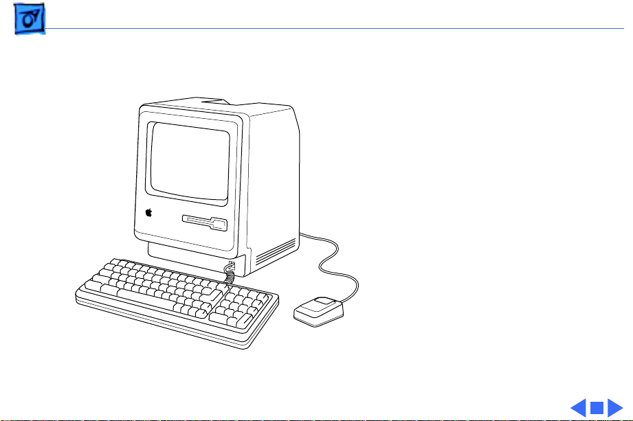
Basics Overview - 1
Overview
This manual includes repair
procedures for the earliest
Apple Macintosh
computers—the Macintosh
128K and Macintosh 512K.
Figure: Macintosh 128k/512K
Page 4

K
Service Source
Specifications
Macintosh
Page 5

Specifications Processor - 1
Processor
CPU
Motorola 68000 microprocessor
7.83 MHz
32-bit internal data bus
Page 6

Specifications Memory - 2
Memory
RAM
ROM
PRAM
128K or 512K
64K
CMOS custom chip with 4.5 V, user-replaceable battery backup
(includes 256 bytes of memory; remembers system
parameters even with the machine switched off)
Page 7

Specifications Disk Storage - 3
Disk Storage
Floppy Drive
Internal, single-sided drive; uses 3.5-in., hard-case, 400K
floppy disks
Page 8

Specifications I/O Interfaces - 4
I/O Interfaces
Floppy Drive
Mouse
Keyboard
Serial
External drive port; DB-19 connector
Mouse port; DE-9 connector
Synchronous serial keyboard bus; RJ-11 connector
Two RS-232/RS-422 serial ports; DE-9 connectors
Page 9

Specifications I/O Devices - 5
I/O Devices
Keyboard
Mouse
58 keys; software mapped; RJ-11 connector
Mechanical tracking; optical shaft encoding at 3.54 pulses per mm
(90 pulses per in.) of travel; DE-9 connector
Page 10

Specifications Sound and Video - 6
Sound and Video
Sound Generator
Video Display
Four-voice sound with 8-bit digital/analog conversion, using
22-kHz sampling rate
9-in. (diagonal) screen; 512 x 342 pixel, bit-mapped display
Page 11

Specifications Electrical - 7
Electrical
Line V oltage
Frequency
Maximum Power
105–125 VAC
50–60 Hz
60 W
Page 12

Specifications Physical - 8
Physical
Dimensions
Weight
Height: 13.6-in. (34.5 cm)
Width: 9.6-in. (24.4 cm)
Depth: 10.9-in. (27.6 cm)
16 lb. 8 oz. (7.5 kg)
Page 13

K
Service Source
Troubleshooting
Macintosh
Page 14

Troubleshooting General/ - 1
General
The Symptom Charts included in this chapter will help you
diagnose specific symptoms related to your product. Because
cures are listed on the charts in the order of most likely solution,
try the first cure first. Verify whether or not the product
continues to exhibit the symptom. If the symptom persists, try
the next cure. (Note: If you have replaced a module, reinstall the
original module before you proceed to the next cure.)
If you are not sure what the problem is, or if the Symptom Charts
do not resolve the problem, refer to the Flowchart for the product
family.
For additional assistance, contact Apple Technical Support.
Page 15

Troubleshooting Symptom Charts/Video - 2
Symptom Charts
Video
No video, but audio
tone is present and
drive operates
Screen is bright and
audio is present, but
no video information
is present
1 Turn contrast control fully clockwise.
2 Check video cable connections.
3 Replace power supply board.
4 Replace neck cable.
5 Replace logic board. Retain customer’s SIMMs.
1 Replace power supply board.
2 Replace logic board. Retain customer’s SIMMs.
Page 16

Troubleshooting Symptom Charts/Drives - 3
Drives
Disk ejects; display
shows disk icon with
blinking “X”
Unable to insert disk
all the way
1 Replace bad disk.
2 Replace floppy drive cable.
3 Replace drive.
4 Replace logic board. Retain customer’s SIMMs.
1 Insert opened paper clip into small hole beside drive slot, or
switch off system power and hold mouse ∑∑button down
while switching system power back on to complete eject
cycle. Then insert disk with metal slot forward and writeprotect tab on bottom.
2 Replace floppy drive.
Page 17

Troubleshooting Symptom Charts/Drives
(Continued)
- 4
Drive does not eject
disk
Does not read disks
on internal drive
Drives
Insert opened paper clip into small hole beside drive slot, or switch
off system power and hold mouse button down while switching
system power back on to complete eject cycle.
1 Replace bad disk.
2 Replace floppy drive cable.
3 Replace Mylar RFI shield.
4 Replace floppy drive.
5 Verify ROMs on the logic board (refer to Additional
6 Replace logic board. Retain customer’s SIMMs.
(Continued)
Procedures).
Page 18

Troubleshooting Symptom Charts/Peripherals - 5
Peripherals
Cursor does not move 1 Connect mouse.
2 Replace mouse.
3 Replace logic board. Retain customer’s SIMMs.
Cursor moves, but
clicking mouse
produces no response
No response to any
key on keyboard
No response from a
particular key
1 Replace mouse.
2 Replace logic board. Retain customer’s SIMMs.
1 Replace keyboard cable.
2 Replace keyboard.
3 Replace logic board. Retain customer’s SIMMs.
1 Replace keyswitch.
2 Replace keyboard.
3 Replace logic board. Retain customer’s SIMMs.
Page 19

Troubleshooting Symptom Charts/Peripherals
(Continued)
- 6
Known-good
ImageWriter or
ImageWriter II does
not print
Known-good
LaserWriter does not
print
Peripherals
1 Make sure that Chooser and Control Panel are set correctly
2 Check that system software version is compatible. Replace
software with known-good version.
3 Reset PRAM.
4 Replace interface cable.
5 Replace logic board. Retain customer’s SIMMs.
1 Make sure that Chooser and Control Panel are set correctly.
2 Check that system software version is compatible. Replace
software with known-good version.
3 Reset PRAM.
(Continued)
Page 20

Troubleshooting Symptom Charts/Miscellaneous - 7
Miscellaneous
When turned on, the
Macintosh
continuously beeps
and tries to power up
Clicking or chirping
sound
1 Perform voltage adjustment. Refer to Adjustments chapter.
2 Disconnect internal disk drive. If this eliminate problem,
replace drive.
3 Replace logic board. Retain customer’s SIMMs.
4
Caution:
new power supply board. Replace power supply board, logic
board, and internal drive, then turn on Macintosh.
1 Connect logic board cable.
2 Perform voltage adjustment. Refer to Adjustments chapter.
3 Replace power supply board.
4 Replace logic board. Retain customer’s SIMMs.
Replacing only power supply board may damage
Page 21

Troubleshooting Symptom Charts/Miscellaneous
(Continued)
- 8
Smoke/odor issues
from the Macintosh
No video, no audio
tone, and no drive
operation
Miscellaneous
Caution:
power supply board. Replace power supply board, logic board, and
internal drive, then turn on Macintosh.
1 Connect power cord.
2 Turn on power.
3 Replace power cord.
4 Check fuse.
5
6 Replace logic board. Retain customer’s SIMMs.
Replacing only power supply board may damage new
Caution:
new power supply board. Replace power supply board, logic
board, and internal drive, then turn on Macintosh.
(Continued)
Replacing only power supply board may damage
Page 22

Troubleshooting Symptom Charts/Miscellaneous
(Continued)
- 9
When developer’s
switch is installed,
Macintosh sometimes
resets intermittently
Macintosh 512K
enhanced has two RFI
shields
Miscellaneous
Remove switch and file it down about 1/16 inch.
Some machines have two RFI shrouds installed. Two RFI shields
can be replaced by one RFI shield, which can be ordered as a
service part.
(Continued)
Page 23

K
Service Source
T ak e Apart
Macintosh
Page 24

Take Apart Cover - 1
Cover
No preliminary steps are
required before you begin
this procedure.
±
Warning:
contains high voltage and a
high-vacuum picture tube.
To prevent serious injury
or equipment damage,
review CRT safety and
discharge instructions in
Bulletins/Safety.
This product
Page 25

Take Apart Cover - 2
Cover
Battery
Compartment
Cover
1 Remove the battery
compartment cover.
2 Remove the reset/
interrupt switch, if
present.
Reset/Interrupt
Switch
Page 26

Take Apart Cover - 3
3 Using a Torx
screwdriver, remove
the four case screws.
4 Using the pull-apart
tool, gently pry off the
cover.
±
Warning:
the metal chassis may
be sharp. When moving
the computer with the
cover off, be sure to
handle the chassis
carefully.
The edges of
Page 27

Take Apart Cover - 4
5 Remove the RFI shield.
RFI Shield
Page 28

Take Apart Power/Sweep Board - 5
Ground Lug
Anode Cap
Discharge
Tool
Power/Sweep Board
Power/Sweep
Board
Before you begin,
• Remove the cover
• Discharge the CRT
• Remove the anode cap
±
Warning:
contains high voltage and a
high-vacuum picture tube.
To prevent serious personal
injury or equipment
damage, review CRT safety
and discharge instructions
Bulletins/Safety.
This product
Page 29

Take Apart Power/Sweep Board - 6
±
Yoke Cable
Logic Board
Cable
Neck Cable
Screw and
Lockwasher
Warning:
grounding wriststrap until
after discharging the CRT.
1 Disconnect the following
cable connectors from
the power/sweep board:
• Yoke cable
• Logic board cable
• Neck cable
2 Remove the screw and
lockwasher that hold the
ground wire to the
chassis.
Never use a
Page 30

Take Apart Power/Sweep Board - 7
3
Note:
You may need to
remove the insulating
paper from the power/
sweep board to access the
mounting screws.
Remove the three
mounting screws and
washers, and lift the
power/sweep board
from the chassis.
Replacement Note:
replacing all parts except
the cover, perform the
voltage and video
adjustment procedures. See
“Voltage” and “Video” in the
Adjustments chapter.
After
Page 31

Take Apart Power/Sweep Board - 8
Replacement Note:
sending a defective power/
sweep board to Apple, be
sure to include the cable that
connects to the logic board.
Be sure the contrast control
knob and battery have been
removed from the defective
board and reinstalled onto
the exchange board.
When
Page 32

Take Apart Logic Board - 9
Logic Board
Before you begin,
• Remove the cover
• Discharge the CRT
±
Warning:
contains high voltage and a
high-vacuum picture tube.
To prevent serious personal
injury or equipment
damage, review CRT safety
and discharge instructions
in Bulletins/Safety.
Logic Board
This product
Page 33

Take Apart Logic Board - 10
±
Warning:
grounding wriststrap until
after discharging the CRT.
1 Disconnect the following
cable connectors from
the logic board:
• Floppy drive cable
• Logic board cable
Logic
Board
Cable
Floppy Drive Cable
Never use a
Page 34

Take Apart Logic Board - 11
2
Caution:
removing the logic
board, be careful not to
damage the SIMMs —
especially the larger DIP
SIMMs that may be
installed on the board.
Pull back on the top of
the logic board, and
carefully slide out the
logic board.
When
Replacement Note:
replacing all parts except
the cover, perform the
voltage and video
adjustment procedures. See
“Voltage” in Adjustments.
After
Page 35

Take Apart Logic Board - 12
Replacement Note:
exchanging the 512K logic
board, you must swap ROMs
to the new logic board.
Replacement Note:
the SIMMs from the
defective logic board and
install them on the
replacement logic board.
See Hardware/Memory.
When
Remove
Page 36

Take Apart CRT - 13
CRT
CRT
Before you begin,
• Remove the cover
• Discharge the CRT
• Remove the Power/
Sweep board
±
Warning:
contains high voltage and a
high-vacuum picture tube.
To prevent serious personal
injury, review CRT safety
and discharge instructions
in Bulletins/Safety.
This product
Page 37

Take Apart CRT - 14
±
Ground
Wire
Warning:
grounding wriststrap until
after discharging the CRT.
±
Warning:
by its sides only. Do not
grasp the neck on the CRT or
touch the anode.
1 Slide the CRT socket
cable straight off the
neck of the CRT.
2 Remove the four
mounting screws and the
ground wire, and lift the
CRT off the bezel.
Never use a
Handle the CRT
Page 38

Take Apart CRT - 15
±
Warning:
dispose of the CRT, refer to
“CRT Disposal” in
Bulletins/Safety.
If you must
Replacement Note:
replace the CRT, perform
the video and yoke
adjustment procedures. See
“Video” and “Yoke” in the
Adjustments chapter.
If you
Page 39

Take Apart Floppy Drive - 16
Floppy Drive
Before you begin,
• Remove the cover
• Discharge the CRT
• Remove the logic board
±
Floppy Drive
Warning:
contains high voltage and a
high-vacuum picture tube.
To prevent serious personal
injury or equipment
damage, review CRT safety
and discharge instructions
in Bulletins/Safety.
This product
Page 40

Take Apart Floppy Drive - 17
Floppy Drive
±Warning:
Never use a
grounding wriststrap until
after discharging the CRT.
Remove the four mounting
screws, and slide the floppy
drive out of the chassis.
Page 41

Take Apart Floppy Drive - 18
Replacement Note:
400K drives are shipped in
their original drive shields.
When installing a new
800K drive, remove the
shipping fixture, plastic
dust shield (if any), and
packing disk from the new
drive. Install the new drive
in the customer’s original
drive shield.
Note:
Before you install a
replacement drive, remove
the dust shield, if there is
one.
All
Page 42

Take Apart Chassis - 19
Chassis
Before you begin,
• Remove the cover
• Discharge the CRT
• Remove the logic board
• Remove the Power/
Sweep board
• Remove the floppy drive
±
Chassis
Warning:
contains high voltage and a
high-vacuum picture tube.
To prevent serious personal
injury or equipment
damage, review CRT safety
and discharge instructions
in Bulletins/Safety.
This product
Page 43

Take Apart Chassis - 20
±
Warning:
grounding wriststrap until
after discharging the CRT.
Remove the five mounting
screws and lift the chassis
off the bezel.
Never use a
Page 44

K
Service Source
Upgrades
Macintosh
Page 45

Upgrades Floppy Drive Upgrade Kit - 1
Floppy Drive Upgrade Kit
Before you begin,
• Remove the cover
• Discharge the CRT
• Remove the logic board
Floppy Drive
±
Warning:
contains high voltage and a
high-vacuum picture tube.
To prevent serious personal
injury or equipment
damage, review CRT safety
and discharge instructions
in Bulletins/Safety.
This product
Page 46

Upgrades Floppy Drive Upgrade Kit - 2
±
D5
D8
Warning:
grounding wriststrap until
after discharging the CRT.
Note:
This kit replaces the
400K floppy drive on a
512K Macintosh with an
800K floppy drive. The kit
contains the new drive and
two new ROMs for the logic
board. The new ROMs
support both the 400K and
the 800K drives. This
upgrade is not recommended
for the 128K Macintosh.
Never use a
Page 47

Upgrades Floppy Drive Upgrade Kit - 3
1 Using an IC extractor,
remove the old ROMs
from locations D5 and
D8.
2 Install the two new ROMs
as follows:
• ROM HI at location D5
D5
D8
• ROM LOW at location
D8
Note:
Be sure that the
notched ends of the
ROMs face the front of
the computer.
Page 48

Upgrades Floppy Drive Upgrade Kit - 4
3 Remove the floppy drive.
Refer to “Floppy
Drive” in the Take Apart
chapter.
Page 49

Upgrades Floppy Drive Upgrade Kit - 5
4 Reinstall the logic board.
See “Logic Board” in
the Take Apart chapter.
Page 50

Upgrades Floppy Drive Upgrade Kit - 6
5 Install the new 800K
floppy drive. See
“Floppy Drive” in the
Take Apart chapter.
6 Return the old ROMs and
the 400K drive to Apple
(refer to the
instructions in the kit).
Page 51

Upgrades Logic Board Upgrade Kit - 7
Logic Board Upgrade Kit
Before you begin,
• Remove the cover
• Discharge the CRT
• Remove the logic board
±
Logic Board
Warning:
contains high voltage and a
high-vacuum picture tube.
To prevent serious personal
injury or equipment
damage, review CRT safety
and discharge instructions
in Bulletins/Safety.
This product
Page 52

Upgrades Logic Board Upgrade Kit - 8
±
D5
D8
Warning:
grounding wriststrap until
after discharging the CRT.
Note:
This kit cannot be
installed unless the Floppy
Drive Upgrade Kit has been
installed. The Logic Board
Upgrade Kit upgrades the
logic board of a 512K Mac to
a Mac Plus. The kit contains
a new logic board with 1 MB
of RAM, an RFI shield, and a
new rear cover.
Never use a
Page 53

Upgrades Logic Board Upgrade Kit - 9
1 Using an IC extractor,
remove the ROMs from
locations D5 and D8 on
the 512K logic board.
2 Install the two ROMs in
the new logic board:
• ROM HI at location D5
D5
D8
• ROM LOW at location
D8
Note:
Be sure that the
notched ends of the
ROMs face the front of
the computer.
Page 54

Upgrades Logic Board Upgrade Kit - 10
3 Install the new logic
board in the computer.
See “Logic Board” in
the Take Apart chapter.
Page 55

Upgrades Logic Board Upgrade Kit - 11
4 Install the new RFI
shield.
5 Install the new cover.
See “Cover” in the Take
Apart chapter.
6 Return the old logic
board, old RFI shield,
and old cover to Apple.
Page 56

Upgrades 400K Drive ROM Upgrade - 12
400K Drive ROM Upgrade
Before you begin,
• Remove the cover
• Discharge the CRT
• Remove the logic board
±
Logic Board
Warning:
contains high voltage and a
high-vacuum picture tube.
To prevent serious personal
injury or equipment
damage, review CRT safety
and discharge instructions
in Bulletins/Safety.
This product
Page 57

Upgrades 400K Drive ROM Upgrade - 13
±
D5 D8
Warning:
grounding wriststrap until
after discharging the CRT.
Note:
Current 400K drives
contain a new stepper motor
that requires the
replacement of the two boot
ROMs on the Macintosh
128K and 512K. The new
ROMs are compatible with
new and old stepper motors.
1 Using an IC extractor,
remove the ROMs at
locations D5 and D8.
Never use a
Page 58

Upgrades 400K Drive ROM Upgrade - 14
2 Install the two new ROMs
on the logic board:
• ROM HI at location D5
• ROM LOW at location
D8
Note:
Be sure that the
notched ends of the
D5
D8
ROMs face the front of
the computer.
Page 59

Upgrades 400K Drive ROM Upgrade - 15
3 Reinstall the logic board
in the computer. See
“Logic Board” in the
Take Apart chapter.
Page 60

K
Service Source
Adjustments
Macintosh
Page 61

Adjustments Voltage - 1
Voltage
Before you begin, remove
the cover.
±
Warning:
contains high voltage and a
high-vacuum picture tube.
To prevent serious personal
injury or equipment
damage, review CRT safety
and discharge instructions
in Bulletins/Safety.
This product
Page 62

Adjustments Voltage - 2
Power/Sweep
Board
External
Drive Port
Caution:
Because you must
make voltage adjustments
from the rear of the
computer, use a mirror to
view the computer screen.
Do not reach around the
computer to adjust the
controls.
Note:
You must verify
voltages after you replace
the logic board or the
power/sweep board.
Page 63

Adjustments Voltage - 3
1 Set the voltmeter to 20 V
scale.
2 Connect the Macintosh
voltage test cable (Apple
part number 077-
0135) to the external
drive port.
External
Drive Port
Caution:
Shorting the test
cable plugs to each other can
damage the Macintosh
computer. Pull the rubber
hoods over the plugs.
3 Connect the black
voltmeter test lead
between the voltmeter
Page 64

Adjustments Voltage - 4
ground terminal and the
computer chassis.
4 Connect the orange test
cable lead to the voltage
input terminal on the
voltmeter.
5 Switch on the computer.
Voltage
Regulator
Power/Sweep
Board
6 Adjust the voltage
regulator on the power/
sweep board to between
11.90 V and 12.75 V.
7 Switch off the power.
8 Disconnect the orange
test lead and pull the
insulated hood over the
plug.
Page 65

Adjustments Voltage - 5
9 Connect the red test
cable lead to the voltage
input terminal on the
voltmeter.
10 Switch on the computer.
11 Adjust the voltage
regulator on the power/
Voltage
Regulator
sweep board to between
4.85 V and 5.15 V.
Power/Sweep
Board
Page 66

Adjustments Voltage - 6
12 Switch off the power.
13 Disconnect the red test
lead
14 and pull the insulated
hood over the plug.
15 Repeat the tests to verify
that both voltages are
Voltage
Regulator
within the specified
tolerances.
Note:
If the power/sweep
board will not adjust so that
Power/Sweep
Board
both voltages fall within
tolerance, replace the board.
Page 67

Adjustments Yoke - 7
Yoke
Before you begin,
• Remove the cover
• Discharge the CRT
±
Yoke
Warning:
contains high voltage and a
high-vacuum picture tube.
To prevent serious personal
injury or equipment
damage, review CRT safety
and discharge instructions
in Bulletins/Safety.
This product
Page 68

Adjustments Yoke - 8
Caution:
make yoke adjustments from
the rear of the computer,
use a mirror to view the
computer screen. Do not
reach around the computer
to adjust the controls.
Note:
CRT, you may need to adjust
the yoke.
Because you must
If you replace the
Page 69

Adjustments Tilt Adjustment - 9
Tilt Adjustment
Note:
If glue holds the yoke
collar in place, use an art
knife to cut through the glue.
1 Loosen the yoke clamp
Yoke Collar
Yoke Clamp
Screw
screw two or three
turns.
2 Switch on the computer.
Page 70

Adjustments Tilt Adjustment - 10
3 With one hand, grasp
the plastic spokes of the
yoke collar and rotate
the yoke collar until the
top and bottom edges of
the picture are parallel
with the top and bottom
Yoke Collar
of the bezel.
Page 71

Adjustments Tilt Adjustment - 11
4 Switch off and unplug the
computer.
5 Discharge the CRT.
6
Caution:
Do not
overtighten the yoke
clamp screw.
Yoke Collar
Hold the plastic collar
Yoke Clamp
Screw
in position and slowly
tighten the yoke clamp
screw so that the collar
cannot slip.
Page 72

Adjustments Tilt Adjustment - 12
7 Replace the cover and
switch on the computer.
8 Make sure the top and
bottom edges of the
picture are parallel with
the top and bottom of the
bezel.
Page 73

Adjustments Tilt Adjustment - 13
Centering Ring Adjustment
1 Turn off the computer
and remove the cover.
2 Turn on the computer
Note:
If glue holds the yoke
collar in place, use an art
knife to cut through the glue.
3 To center the picture,
hold the front centering
ring steady and move the
rear ring. Then hold the
rear centering ring
Centering Rings
steady and move the
front ring.
Page 74

Adjustments Video - 14
Power/Sweep
Board
Video
Before you begin, remove
cover.
±
Warning:
contains high voltage and a
high-vacuum picture tube.
To prevent serious personal
injury, review CRT safety
and discharge instructions
in Bulletins/Safety.
Note:
You must perform the
video adjustments whenever
the CRT or the power/sweep
board is replaced.
Switch on the computer.
This product
Page 75

Adjustments Video - 15
Contrast and Brightness
1 Turn the external
contrast control fully
clockwise.
Brightness
Control
External
Contrast
Control
2 Turn the brightness
control fully
counterclockwise so that
white lines are visible.
3 Turn the brightness
control clockwise until
the white lines just
disappear.
4 Turn the external
contrast control 1/8 of a
turn counterclockwise.
Page 76

Adjustments Video - 16
Size Adjustment
1 Using an alignment tool,
adjust the width control
until the raster is 7
Width Control
Height Control
inches (177.8 mm)
wide.
2 Using an alignment tool,
adjust the height control
until the raster is 4.7
inches (119.4 mm)
high.
Page 77

Adjustments Video - 17
Focus Adjustment
1 Turn the focus control
clockwise to its limit.
2 Turn the focus control
counterclockwise 1/8 of
a turn.
Focus Control
Page 78

K
Service Source
Exploded V ie w
Macintosh
Page 79

Exploded View 1
Exploded View
Internal Drive
Shield
805-0765 (400K)
805-0217 (800K)
Floppy Drive
661-7615 (400K)
661-0345 (800K)
Internal
Drive
Cable
590-0167 (red)
590-0437 (yellow)
Insulator
Shield
725-0011
Front
Bezel
810-0373
CRT and Yoke
Assembly
076-0103
CRT
Socket
Cable
590-0160
Chassis
805-0766
Rear Housing
630-5139
462-3100
Power/Sweep
Board
661-76214
426-1001
Logic Board
661-06236
RFI Shroud
805-0577
426-1007
435-5002
 Loading...