

Page 1

Logic Pro 8
Control Surfaces
Support
Page 2

Apple Inc.
© 2007 Apple Inc. All rights reserved.
Under the copyright laws, this manual may not be
copied, in whole or in part, without the written consent
of Apple. Your rights to the software are governed by
the accompanying software licence agreement.
The Apple logo is a trademark of Apple Inc., registered
in the U.S. and other countries. Use of the “keyboard”
Apple logo (Option-Shift-K) for commercial purposes
without the prior written consent of Apple may
constitute trademark infringement and unfair
competition in violation of federal and state laws.
Every effort has been made to ensure that the
information in this manual is accurate. Apple Inc. is not
responsible for printing or clerical errors.
Note: Because Apple frequently releases new versions
and updates to its system software, applications, and
Internet sites, images shown in this book may be slightly
different from what you see on your screen.
Apple Inc.
1 Infinite Loop
Cupertino, CA 95014-2084
408-996-1010
www.apple.com
Apple, FireWire, iPod, Logic, Mac, Macintosh, and Mac OS
are trademarks of Apple Inc., registered in the U.S. and
other countries.
GarageBand is a trademark of Apple Inc.
Intel, Intel Core, and Xeon are trademarks of Intel Corp.
in the U.S. and other countries.
Other company and product names mentioned herein
are trademarks of their respective companies. Mention
of third-party products is for informational purposes
only and constitutes neither an endorsement nor a
recommendation. Apple assumes no responsibility with
regard to the performance or use of these products.
Page 3

8
9
12
12
13
16
18
19
22
29
32
33
36
38
55
56
57
58
61
3
Contents
Preface 7 Introduction
7 What Are Control Surfaces?
Using Control Surfaces With Logic Pro
Control Surfaces Supported by Logic Pro
Control Surface Plug-ins
About Software and Firmware
About This Guide
Chapter 1 15 Basic Control Surface Setup
15 Getting Started
Connecting Control Surfaces
Adding Control Surfaces to Logic Pro
Creating Control Surface Groups
Configuring Your Control Surface Setup
Setting Control Surface Preferences
Modal Dialog Display
Usage Tips
Chapter 2 35 Customizing Controller Assignments
35 Assigning Controllers to Logic Pro Parameters
Working in Easy View
Working in Expert View
Assigning Buttons to Key Commands
Controller Assignments Storage
Chapter 3 57 Mackie Control
57 Setting Up Your Mackie Control
Using the Mackie Control With Logic Pro
Display Zone
Channel Strip Controls
64
Master Fader
64
Assignment Zone
79
Fader Bank Zone
81
Function Key Zone
3
Page 4

4
82
83
83
85
86
93
Global View Zone
Modifier Buttons
Automation Buttons
Utilities Buttons
Transport Zone
Cursor Key Zone
Jog/Scrub Wheel Zone
Programmable User Modes
Connecting Foot Switches
Assignment Overview
Chapter 4 107 M-Audio iControl
10 7 Setting Up Your iControl
10 7 Editing Plug-in Parameters
10 8 Assignment Buttons
11 0 Arrow Up and Arrow Down Buttons
11 0 Channel Strip Controls
112 Mixer View and Channel View
112 The Jog Wheel
112 Transport Controls
113 Master Fader
11 4 Assignment Overview
94
95
95
96
Chapter 5 117 EuCon Support of Euphonix MC and System 5-MC
117 Setting Up Your MC or System 5-MC
11 8 Setting Up Soft Key Assignments
11 9 Main-Tracks Touchscreen
11 9 Main-Layouts
12 0
Faders
12 0
Choosing Automation Modes
121
Using Knobsets
12 6
Monitors and Control Room
12 6
Clear Keys
12 7
Track Control Bar
12 7
System 5-MC Specific Features
Chapter 6 129 CM Labs Motormix
12 9
Setting Up Your CM Labs Motormix
12 9
Assignment Overview
Chapter 7 137 Frontier Design TranzPort
13 7
Setting Up Your Frontier Design TranzPort
13 7
LCD
13 8
Assignment Overview
Contents
Page 5

Chapter 8 141 JLCooper CS-32 MiniDesk
141 Setting Up Your JL Cooper CS-32 MiniDesk
14 2 Assignment Overview
Chapter 9 147 JLCooper FaderMaster 4/100
14 7 What You Will Need
14 7 Setting Up Your JLCooper FaderMaster 4/100
14 8 Assignment Overview
Chapter 10 149 Korg microKONTROL and KONTROL49
14 9 Setting Up Your Korg microKONTROL and KONTROL49
15 0 Assignment Overview
Chapter 11 155 Mackie Baby HUI
15 5 Setting Up Your Mackie Baby HUI
15 6 Assignment Overview
Chapter 12 159 Mackie C4
15 9 Setting Up Your Mackie C4
15 9 V-Pots, V-Selects
166 Buttons at Bottom
169 Marker Overlay
169 Track Overlay
17 0 Channel Strip Overlay
17 0 Function Overlay
Chapter 13 173 Mackie HUI
17 3 Setting Up Your Mackie HUI
174 Assignment Overview
Chapter 14 183 Radikal Technologies SAC-2K
183 Setting Up Your Radikal Technologies SAC-2K
18 4 Assignment Overview
18 8 Troubleshooting
Chapter 15 189 Roland SI-24
18 9
Setting Up Your Roland SI-24
19 0
Assignment Overview
Chapter 16 195 Tascam FW-1884
19 5
Introduction
19 5
Setting Up Your Tascam FW-1884
19 6
Assignment Overview
Contents
5
Page 6

Chapter 17 203 Tascam US-2400
203 Setting Up Your Tascam US-2400
204 Assignment Overview
Chapter 18 211 Tascam US-428 and US-224
211 Setting Up Your Tascam US-428 and US-224
211 Assignment Overview
Chapter 19 215 Yamaha 01V96
215 Setting Up Your Yamaha 01V96
216 Assignment Overview
218 SELECTED CHANNEL Section
219 Data Entry Section
219 Channel Strips
219 Stereo Channel Strip Section
219 User Defined Keys Section
Chapter 20 223 Yamaha 02R96
223 Setting Up Your Yamaha 02R96
224 Assignment Overview
6
Chapter 21 229 Yamaha DM1000
229 Setting Up Your Yamaha DM1000
230 Assignment Overview
Chapter 22 237 Yamaha DM2000
237 Setting Up Your Yamaha DM2000
238 Assignment Overview
Contents
Page 7

Introduction
You can use hardware control surfaces to control and
automate transport, mixing, recording, and other tasks in
Logic Pro.
All of the Logic Pro functions which correspond to mixer controls, such as setting
volume level and pan position, can be performed onscreen—using your mouse and
computer keyboard. This is not an optimal method for precise real time control. You
can expand your creative experience, and achieve greater flexibility and precision, by
connecting a hardware control surface to your computer, and using it with Logic Pro.
When you move a fader on the control surface, the corresponding fader in Logic Pro
moves with it. Similarly, when you adjust a control onscreen, the corresponding control
on the control surface moves to the same position. You can adjust EQ or other
parameters by turning the rotary knobs on the control surface, and have the
corresponding parameters update instantly in Logic Pro.
Preface
What Are Control Surfaces?
Control surfaces are hardware devices that feature a variety of controls, which can
include faders, rotary knobs, switches, and displays. These controls can be mapped to
functions in Logic Pro, allowing you to change parameters—such as volume or
panning—with more precision than by using your mouse and computer keyboard. You
can also control multiple parameters at the same time.
Control surfaces also typically provide buttons that allow you to select parameters for
editing, or to select particular tracks/channel or banks (of channels). Many also offer a
jog wheel, which allows you to move the playhead precisely, Transport buttons, such as
Play, Rewind, and so on, and other controls. When you use a supported control surface
with Logic Pro, some controls are pre-mapped to common functions. You can map
non-assigned controls to other Logic Pro commands and functions (see “Assigning
Controllers to Logic Pro Parameters” on page 35).
7
Page 8

Some simple control surfaces only provide (non-motorized) faders and knobs. More
sophisticated units include motorized faders, rotary encoders, LED rings, and
programmable displays. The additional feedback these control surfaces provide make
them easier to use—without having to refer to your computer screen to know what
mode the device is in, or what current parameter values are.
Using Control Surfaces With Logic Pro
To use a control surface with Logic Pro, you connect the control surface to your
computer (via MIDI, USB, a Network port, or FireWire). You then add it to Logic Pro (this
is automatic for many supported devices), map the controls you want to use to
Logic Pro commands (again, much of this is done for you, if using a supported device),
then use the control surface as you play and record.
Recorded control surface automation appears in (the Arrange, when enabled, and in
the Piano Roll Editor). For detailed information about connecting and adding control
surfaces, see Chapter 1, “Basic Control Surface Setup,” on page 15. Please read this
chapter before moving to the chapters for your particular control surfaces.
The following outlines some of the things you can accomplish when using control
surfaces with Logic Pro:
 Control transport functions, including setting locators, and activating Cycle or Punch
Recording modes.
 Adjust instrument, aux, master, and audio channel volume and pan levels.
 Select, and control, all effect and instrument parameters.
 Select, solo, mute, and record-enable tracks/channels.
 Set and adjust send parameters.
 Remotely switch between screensets.
 Scrub MIDI and audio (in the Arrange window).
 Zoom in on individual tracks, or the window with key focus.
 Create, delete, and move the playhead between markers.
Control surfaces allow you to create a dynamic live performance using a control surface
along with a laptop, a music keyboard, and audio and MIDI interfaces. Some devices
incorporate a music keyboard, audio and MIDI interfaces, and a control surface into a
single integrated unit.
The track automation facilities of Logic Pro can be active even when the application is
not in record mode, allowing you to capture your live real time changes for later
playback. This ensures that you’ll never again lose that “once-in-a-lifetime”
performance—on stage or in the studio.
8 Preface Introduction
Page 9

Logic Pro directly supports a variety of control surfaces, as mentioned, but also allows
you to remap existing assignments for supported control surfaces, or to program new
assignments for unsupported control surfaces. This allows you to extend the use of
faders, knobs, and switches—either directly, or through the use of modifier commands.
You can use any combination of control surfaces with Logic Pro. You will get the most
out of them when used in a control surface group. A detailed overview of group,
installation, and other control surface setup parameters is found in “Creating Control
Surface Groups” on page 19.
The best way to learn about using control surfaces is to adopt a hands-on approach—
moving faders, turning knobs, and using the other controls on your device as you read
through the manual. This will help you to get a feel for how your control surface works,
and how the various parts of the control surface interact with Logic Pro.
Control Surfaces Supported by Logic Pro
Following is an alphabetical listing of control surfaces directly supported by Logic Pro.
The list contains cross references to the relevant device-specific sections.
Note: It is possible that your device may be directly supported in Logic Pro via one or
more downloadable support files. This is often, a driver or plug-in (see “Control Surface
Plug-ins” on page 12), supplied by the manufacturer. Please check the documentation/
discs that came with the device, and the manufacturer’s website. Follow any written
instructions supplied with the files, if available.
Supported Devices Manufacturer Notes
01V96 Yamaha The Yamaha 01V96 emulates two HUI units, using
two virtual MIDI in and out connections over its
USB cable.
See “Yamaha 01V96” on page 215.
01X Yamaha The Yamaha 01X emulates a Mackie Control. It
does not feature all controls available to the
Mackie units, however. Please refer to the 01X
documentation for details.
Logic Pro recognizes the 01X as an 01X, and
displays a custom icon, but communication is as
with a Mackie Control unit.
See “Mackie Control” on page 57.
02R96 Yamaha The Yamaha 02R96 emulates three HUI units,
using three virtual MIDI in and out connections
over its USB cable.
See “Yamaha 02R96” on page 223.
Baby HUI Mackie The Baby HUI is a stripped-down version of the
HUI. See “Mackie Baby HUI” on page 155.
Preface Introduction 9
Page 10

Supported Devices Manufacturer Notes
C4 Mackie The Mackie C4 is directly supported.
See “Mackie C4” on page 159.
CM408T (System 5 MC) Euphonix See “EuCon Support of Euphonix MC and System
5-MC” on page 117.
CS-32 MiniDesk JLCooper See “JLCooper CS-32 MiniDesk” on page 141.
DM1000 Yamaha The Yamaha DM1000 emulates two HUI units,
using two virtual MIDI in and out connections
over its USB cable.
See “Yamaha DM1000” on page 229.
DM2000 Yamaha The Yamaha DM2000 emulates three HUI units,
using three virtual MIDI in and out connections
over its USB cable.
See “Yamaha DM2000” on page 237.
FaderMaster 4/100 JLCooper See “JLCooper FaderMaster 4/100” on page 147.
FE-8 Tascam Extension unit for FW-1884. See “Tascam FW-
18 84 ” on page 195.
FW-1082 Tascam A stripped-down version of the FW-1884.
See “Tascam FW-1884” on page 195.
FW-1884 Tascam See “Tascam FW-1884” on page 195.
HUI Mackie Important: HUI support has been tested with the
original Mackie HUI. There are a number of
control surfaces—not mentioned here—which
can emulate the HUI. Not all devices capable of
HUI emulation have been tested. These are not
supported by Apple, nor are they guaranteed to
work with Logic Pro in HUI emulation mode.
See “Mackie HUI” on page 173.
iControl M-Audio See “M-Audio iControl” on page 107.
KONTROL49 Korg A larger version of the microKONTROL. See “Korg
microKONTROL and KONTROL49” on page 149.
Logic Control XT Mackie/Emagic This is the extension unit for the Logic Control. It
only offers the channel strip section, making it
less useful without a Logic (or Mackie) Control.
See “Mackie Control” on page 57.
Also see the Appendix for more details.
Logic/Mackie Control Mackie/Emagic See “Mackie Control” on page 57.
Also see the Appendix for more details.
10 Preface Introduction
Page 11

Supported Devices Manufacturer Notes
Mackie Control Mackie The original Mackie Control hardware is similar to
the Logic Control. The front panel legend is
different, however. You should request a Logic
Control Lexan Overlay from Mackie. As Logic Pro
also recognizes the Mackie Control protocol, you
may use any firmware version. If your unit has
firmware version 1.02 or higher, you can freely use
either the Logic Control or Mackie Control mode.
See “Mackie Control” on page 57.
Mackie Control Extender Mackie Mackie-badged version of the Logic Control XT.
As Logic Pro also recognizes the Mackie Control
protocol, you may use any firmware version. If
you have firmware version 1.02 or higher, you can
freely use either the Logic Control or Mackie
Control mode. See “Mackie Control” on page 57.
Mackie Control Universal Mackie A Mackie Control with Logic Control silk
screening (legend) and firmware version 2.0 or
higher (including HUI emulation). As Logic Pro
also recognizes the Mackie Control protocol, you
may use any firmware version. If you have
firmware version 1.02 or higher, you can freely use
either the Logic Control or Mackie Control mode.
See “Mackie Control” on page 57.
MC Euphonix See “EuCon Support of Euphonix MC and System
5-MC” on page 117.
microKONTROL Korg See “Korg microKONTROL and KONTROL49” on
page 149.
Motormix CM Labs See “CM Labs Motormix” on page 129.
Radikal Technologies SAC-2.2 The SAC-2.2/2k’s native mode is directly
supported, but it can also emulate a Mackie
Control. You should use the native mode.
See “Radikal Technologies SAC-2K” on page 183.
Radikal Technologies SAC-2k See “Radikal Technologies SAC-2K” on page 183.
SI-24 Roland See “Roland SI-24” on page 189.
TranzPort Frontier Design Group See “Frontier Design TranzPort” on page 137.
US-224 Tascam A stripped-down version of the US-428.
See “Tascam US-428 and US-224” on page 211.
US-2400 Tascam Logic Pro supports the US-2400’s native mode. In
contrast to its Mackie Control mode, all controls,
including the joystick, are supported.
See section “Tascam US-2400” on page 203.
US-428 Tascam See “Tascam US-428 and US-224” on page 211.
Preface Introduction 11
Page 12

Control Surface Plug-ins
Supported control surfaces communicate with Logic Pro via special plug-in files that
are installed along with Logic Pro. The plug-in files are located in the /Contents/MIDI
Device Plug-ins subfolder of the Logic Pro application bundle. To view the bundle
contents, Control-click the Logic Pro application icon, and choose Show Package
Contents from the menu. Logic Pro also checks for control surface plug-ins installed in
the (optional) /Library/Application Support/Logic/MIDI Device Plug-ins and ~/Library/
Application Support/Logic/MIDI Device Plug-ins (the “~” denotes your user home
directory) folders.
When new control surface plug-ins are released independently from a Logic Pro update
(or supplied directly by the device manufacturer), please place them in the folders
described above (or as advised in the documentation supplied with the plug-in).
About Software and Firmware
Most control surfaces depend on Logic Pro for their functionality, and cannot be
operated if Logic Pro is not running. They do not provide any additional functionality
that is not available in Logic Pro itself. One advantage of this approach is that as new
functions are added to Logic Pro, or as you create new assignments, your control
surface will be able to access and control them.
Most control surface units do include a form of software called firmware. Firmware is
similar to the low-level boot software found in your computer, cellular phone, iPod, and
so on.
New behaviors, such as improved control of motorized faders and changes to the
display, can be provided by firmware updates. You should periodically check the
manufacturer’s website for your device, to check for updates that may enhance use or
performance.
The firmware is usually stored on an EEPROM (Electronically Erasable Programmable
Read-Only Memory) chip. It can often be updated via a simple MIDI dump procedure,
in the form of a MIDI file. Should new firmware become available, you can simply
download the appropriate MIDI file and play it (from Logic Pro) to your control surfaces,
which will be updated accordingly. The steps required to perform a firmware update
will be outlined in the documentation that accompanies the MIDI file. Please read this
before attempting any update.
Note: Some control surfaces may require that you physically replace the chip for
firmware updates. Please contact the manufacturer of your device for details.
12 Preface Introduction
Page 13

About This Guide
This document assumes that you are familiar with the basic use and terminology of
Logic Pro. The functionality and uses of individual Logic Pro parameters are not
covered. Please consult the Logic Pro 8 User Manual if you require further information.
The next chapter, “Basic Control Surface Setup,” describes general setup procedures
that are common to all control surfaces. The following chapters provide information
about setting up and using specific devices. Please note that these chapters are limited
to describing Logic-specific functions, and are not intended to replace the
manufacturer supplied documentation for the device.
Preface Introduction 13
Page 14

Page 15

1 Basic Control Surface Setup
1
Regardless of the device, you first need to connect, add, and
configure your control surface for use with Logic Pro.
This chapter describes aspects of the setup procedure, and preferences, that are
common to all control surfaces. Setup information for specific devices is covered in the
following chapters.
Important: Please read this chapter first, then read through the chapter that pertains
to your specific device.
Getting Started
To use one or more control surfaces with Logic Pro, you will need:
 An installed, authorized copy of Logic Pro.
 For USB or FireWire-equipped devices (such as a Yamaha 01X), a free USB or FireWire
port. Ideally, this should be a direct USB/FireWire connection with the computer,
rather than via a USB/FireWire hub. Please refer to the documentation provided by
the manufacturer of your control surface.
 For devices that are only equipped with MIDI ports (such as a Mackie Control), a MIDI
interface with free MIDI input and output ports for each device. As an example; if
using a MIDI interface with 8 MIDI input and 8 MIDI output ports—with one Mackie
Control and one Mackie Control XT unit—you will need to use two of the interface’s
MIDI in, and two of its MIDI out ports.
 An installed driver (if required by your control surface) that is supported by the
operating system version you are using on your computer.
Important: Your MIDI interface must feature driver software that supports SysEx
communication. Please consult the documentation that shipped with your MIDI
interface (or MIDI interface drivers).
15
Page 16
The number of devices that can be used simultaneously depends on the number of
free ports of the appropriate type (USB, FireWire, or other) available on your system. In
a standard setup, you can use a single control surface—or one accompanied by one or
more expansion devices. You can also create control surface groups, as discussed in
“Creating Control Surface Groups” on page 19.
Using multiple control surfaces allows you to control more tracks/channels, effects, and
other parameters simultaneously. For example, the Mackie Control XT devices are
basically identical to the channel strip section (fader, V-Pot, and LCD) of the main
Mackie Control unit. The Mackie C4 features a number of V-Pots, but no faders. You can
add as many XT, C4, or other control surface devices as you wish to your system,
provided that enough free MIDI in and out (or USB or other suitable) ports are
available.
Connecting Control Surfaces
Logic Pro supports a variety of control surfaces that connect to your computer using
FireWire, USB, and other connection protocols. Be sure to check the type of connection
that your device features, and that it is supported by your computer. Before connecting
the device, read the installation instructions included with it, and install the latest
version of any appropriate firmware or driver software, if needed. For more information,
refer to the documentation that came with the device.
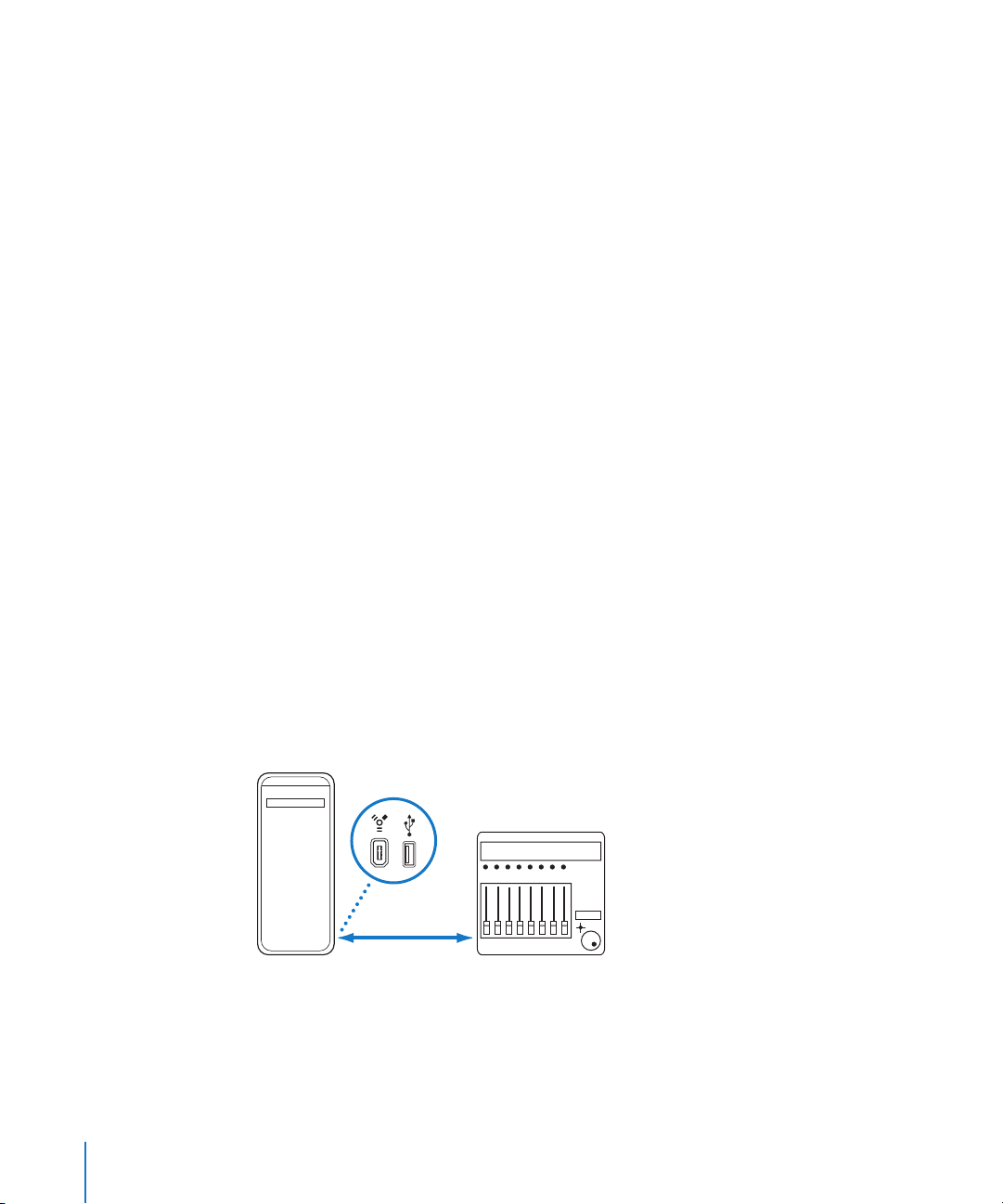
Connecting FireWire and USB Control Surfaces
If your control surface has a FireWire or USB port, you can connect it directly to your
computer, using a cable with the appropriate connectors. FireWire and USB devices
transmit and receive data through a single cable, if the device supports bi-directional
communication. The following diagram illustrates a typical setup using a FireWire or
USB cable:
FireWire/USB
Computer
It is recommended that you connect FireWire and USB devices directly to your
computer, rather than through a hub. Daisy-chaining devices can result in errors and
other problems, due to the amount of data transmitted in real time.
cable
Control surface
16 Chapter 1 Basic Control Surface Setup
Page 17
Connecting Control Surfaces via Networking Ports
A handful of devices are connected via the network (LAN) ports of your Macintosh,
using a single, standard (CAT5) networking cable. Most devices connected in this way
also incorporate audio I/O, and digital audio converters, plus built-in MIDI ports—
making the addition of these peripherals a simple, single cable (and driver) installation.
As with FireWire and USB, it is recommended that such devices are directly connected
to the computer, rather than through a network hub or switch.
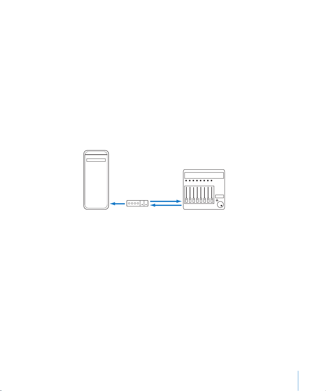
Connecting MIDI Control Surfaces
If your control surface has MIDI input and output ports, you can connect it to a MIDI
interface, and connect the MIDI interface to your computer. MIDI interfaces are typically
connected to your computer via the USB or FireWire connection protocols. MIDI uses
separate ports for input and output, and you must connect both the MIDI input and
output to use the device with Logic Pro. The following diagram illustrates a typical
setup using MIDI input and output:
MIDI
interface
Computer
Out port In port
Out portIn port
Control surface
It is recommended that you do not “daisy-chain” other MIDI devices via MIDI thru to the
MIDI in or out ports used by control surfaces. Daisy-chaining can result in errors and
other problems, due to the amount of data transmitted in real time.
Optional Footswitches and Pedals
Some control surfaces allow you to connect footswitches or pedals as additional
controllers. If your control surface features suitable connectors, you may connect
optional foot switches to remotely control playback and other functions. This frees your
hands for other controls, and can also be helpful when using guitars or other
instruments that require two-handed playing.
Chapter 1 Basic Control Surface Setup 17
Page 18

Powering Up
Once everything is connected, press the power switch on your control surface. Once
powered, the displays (such as an LCD, if your device has one) or LEDs are lit. Some
LCDs display a welcome message, which includes the firmware version number, during
power-up. On most control surfaces with motorized faders, each fader will slide to its
top position, then back to its bottom or center position. This self-diagnostic power-on
procedure indicates that your units are functioning correctly.
Generally, you can turn on your computer (and MIDI interface, if applicable) either
before or after you turn on the control surface, and open Logic Pro either before or
after the control surface is powered up. Some devices, however, may require the
computer to be turned on before/after the device has initialized. Check the device
documentation, and manufacturer web site.
Adding Control Surfaces to Logic Pro
Some control surfaces (such as the Mackie Control) are detected automatically when
you open Logic Pro. You can add other devices that are not detected automatically—in
the Setup window. There are two ways to add a device: by scanning, or by adding the
device manually.
Installation is easy (and is covered in the Setup section of the chapter for your
particular device). Some devices may require different or additional steps, but generally,
all you need to do is select the devices that you want to use with Logic Pro, using one
of the following procedures:
To add a control surface by scanning:
1 Open the Control Surfaces Setup window by choosing Logic Pro > Preferences >
Control Surfaces > Setup.
2 In the Setup window, choose New > Install, and then select the device from the list.
Note: You may select more than one model by Command-clicking on multiple entries
in the list. If you select more than one model, Logic Pro performs the desired operation
for each model, in turn.
3 Click the Scan button. You can also press Enter, or double-click on the device name to
initiate the scan.
Logic Pro scans your system for connected devices, and automatically installs (and
connects to) those it finds.
4 When you are finished, close the window.
If you don’t want to select the models to be scanned, you can simply choose New >
Scan All in the Setup window: Logic Pro searches for all supported control surface
units on all MIDI ports. Please be aware that this may take a while.
18 Chapter 1 Basic Control Surface Setup
Page 19

Some control surfaces don’t support automatic scanning. Such devices must be added
manually to your setup. When you add a device manually, you also need to assign the
appropriate MIDI In and Out port parameters.
Note: It is preferable to install devices by scanning, whenever possible. Logic Pro is able
to gather more information about devices through scanning, than via manual
installation.
To add a control surface manually:
1 Open the Control Surfaces Setup window by choosing Logic Pro > Preferences >
Control Surfaces > Setup.
2 In the Setup window, choose New > Install, and select the desired device from the list.
3 Click the Add button.
4 Close the Install window when you’ve finished.
If another control surface of the selected type already exists in your setup, a warning
dialog will ask you to confirm the addition of the new device.
You need to manually alter the MIDI In and Out port values—in the Device Parameter
box of the Setup window—to match those of the connected unit.
Rebuilding Defaults
You can re-initialize the support of all connected control surfaces by choosing
Logic Pro > Preferences > Control Surfaces > Rebuild Defaults.
Creating Control Surface Groups
If you have multiple control surface units in your system, you can define how they
relate to each other, and create control surface groups. A control surface group consists
of multiple devices that you combine to create a single, unified virtual control surface.
You can create up to 20 control surface groups. Each group can consist of any number
of physical devices. The only limiting factor is the number of available MIDI in and out
ports (or USB/FireWire “MIDI” ports, if you are using a USB or FireWire control surface).
You can independently determine the default behavior of each device in a group. For
more information, see the Device Parameters (p. 22) section.
Chapter 1 Basic Control Surface Setup 19
Page 20
To create a control surface group:
1 Open the Control Surfaces Setup window by choosing Logic Pro > Preferences >
Control Surfaces > Setup.
2 In the Setup window, drag the icons of the control surfaces you want to group, so that
they form a single horizontal row.
The order of the icons from left to right defines the order in which tracks and
parameters are arranged on the devices.
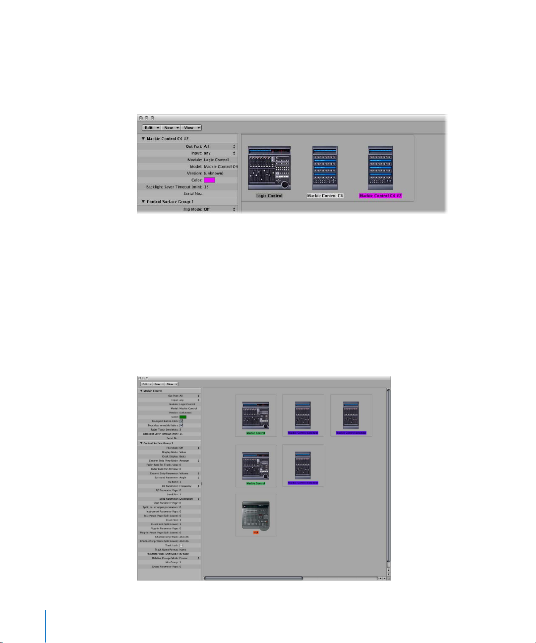
To use two control surfaces independently:
1 Open the Control Surfaces Setup window by choosing Logic Pro > Preferences >
Control Surfaces > Setup.
2 In the Setup window, arrange the icons for the control surfaces in separate rows—that
is, one above the other.
Pictured below is an example with two Mackie Controls, three Mackie Control XTs, and
one HUI: The computer icon is connected to all three rows, as shown below:
20 Chapter 1 Basic Control Surface Setup
Page 21

The top row, consisting of the Mackie Control #1, Mackie Control XT #1, and Mackie
Control XT #2 forms a single control surface group with 24 channels. Mackie Control #1
controls channels 1 to 8, XT #1 controls channels 9 to 16, and XT #2 handles channels
17 to 24.
In the second row, the Mackie Control #2 and Mackie Control XT #3 form a second
control surface group—controlling instruments (on channels 1 to 8) and auxes (on
channels 9 to 16).
In the third row, the HUI forms a single unit control surface group.
Each group has individual settings, such as Flip Mode, Display Mode, Plug-in Parameter
Bank Offset and others. This allows you to access, edit, and automate different sections
of the Logic Pro Mixer.
In our example, the three units in the top row could be used to control audio tracks
and MIDI channels. In the second row, Mackie Control #2 could be used for instrument
channels 1 to 8, and XT #3 could be used for aux channels. The HUI could be used to
edit group definitions. The physical placement of units, and the way you use them, is
completely flexible.
Note: In most situations, the placement of your control surface units in relation to each
other should be the same onscreen as in the real world. Simply position the icons in
your control surface group accordingly.
Once you have created a control surface group, you can configure it in the Setup
window. For more information, see “Control Surface Group Parameters” on page 23.
Follow Control Surface Group
The View Menu in the Mixer window contains a Follow Control Surface Group option.
When enabled, this will update the Mixer window to reflect the active control surface
group.
Following the example above, pressing the track/channel select 2 button of Mackie
Control #2 (in the second row/control surface group), would update the Logic Pro
Mixer to show Instrument channels 1 to 8, and eight Aux channels. Pressing a Select
button on any of the units in the top row/group would update the Mixer to show audio
channels 1 to 24.
Chapter 1 Basic Control Surface Setup 21
Page 22
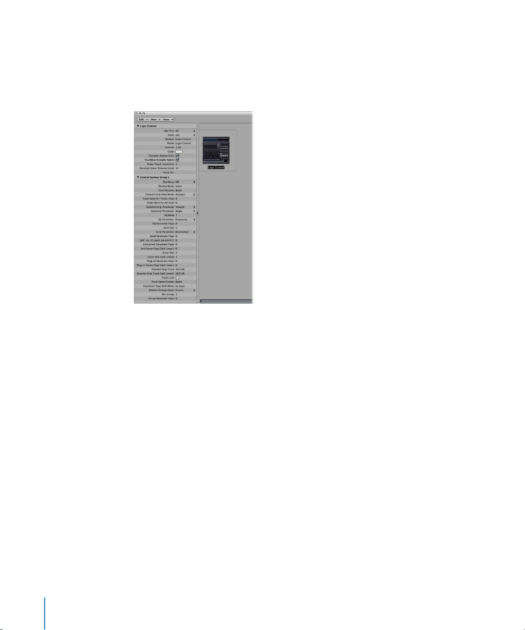
Configuring Your Control Surface Setup
The left side of the Setup window contains two or three parameter boxes: Device
parameters, Special parameters (if your connected device supports them), and Control
Surface Group parameters. You can configure your control surface setup to meet your
needs by editing the parameters in these boxes.
Device Parameters
The Device Parameter box contains the following parameters:
 Out Port: Choose the MIDI output port from the pop-up menu.
 Input: Choose the MIDI input port from the pop-up menu.
 Module: Shows the name of the control surface.
 Model: Shows the model name of the control surface.
 Version: Shows the firmware version for some control surfaces.
 Color: Click to choose the color that indicates which tracks are being controlled by
this control surface. In the Arrange window, the tracks controlled by this device are
colored along the left edge of the track list (if the track control bars are displayed).
Each control surface must be connected to an independent MIDI in and out port (or
corresponding USB/FireWire port, designated as a MIDI port by the device driver).
When the device is added, the automatic setup or scan procedure sets the appropriate
MIDI input and output port settings for the device. If the MIDI port settings are
incorrect, you can manually choose them from the Input and Out port pop-up menus.
22 Chapter 1 Basic Control Surface Setup
Page 23

Special Parameters
Some control surfaces (such as the Mackie Control) allow you to define “special”
parameters such as fader touch sensitivity. When a device that offers special
parameters is connected, the Special Parameters box appears on the left side of the
Setup window. For more information about supported special parameters, refer to the
documentation for the specific device.
Control Surface Group Parameters
If you have created one or more control surface groups, you can configure group
parameters in the Control Surface Group Parameter box. These parameters apply to the
group associated with the selected device, and allow you to set up each group to meet
your needs. This is especially helpful when you have multiple control surface groups.
Many (if not all) control surface group parameters can also be changed directly from
the control surface, as well as from the Setup window.
If you have created multiple control surface groups, the Control Surface Group
Parameter box shows the settings for the group that is currently selected in the Setup
window.
The Control Surface Group Parameter box contains the following parameters:
Display Parameters
The parameters at the top of the box allow you control over aspects of the device
displays.
 Flip Mode: Choose the functions for the faders and rotary encoders of the channel
strips on the device. For control surfaces that contain a fader and a rotary encoder for
each channel strip, Flip Mode allows you to assign both controls to the same
parameter, or swap their assignments. The choices are:
 Off: Standard mode, with the fader acting as a volume control.
 Duplicate: Assigns both the fader and encoder to the currently selected encoder
parameter.
 Swap: Switches the fader and encoder assignments, making the fader a pan
control and the encoder a channel volume control, for example.
 Mute: Disables the fader. This is useful when recording in the same room as the
control surface, and you wish to avoid the mechanical noise of the faders. Any
existing automation still functions normally.
 Display Mode: Click to limit the device display to only the name or only the value of
the current parameter. This is helpful if there is insufficient space for the display of
both the parameter name and value.
 Clock Display: If your control surface features a position display, this parameter allows
you to determine how the playhead position is represented: Click to switch between
Beats (musical values) or SMPTE (absolute time values).
Chapter 1 Basic Control Surface Setup 23
Page 24

Note: The exact elements displayed, and thus their positions, depend on the selected
SMPTE or bar/beat display option defined in the Logic Pro Preferences.
 Channel Strip View Mode:
 Arrange: The channel strips on the device correspond to Logic Pro channel strips
as they appear in the Mixer window. The layout of channel strips matches the way
tracks are laid out in the Arrange window. Channel strip 1 in the Mixer window is
equivalent to channel 1 on the control surface, channel strip 2 in the Mixer is
equivalent to channel 2, and so on. Instruments/channels used by multiple tracks
are merged into one channel. This is the default mode of most devices, including
the Mackie Control.
 All: The channel strips on the device correspond to Logic Pro channel strips of
certain type, such as MIDI or aux channels, independent of their use in tracks.
Control surfaces that support this view mode generally allow you to define which
channel types you want to display. The Mixer window contents automatically
follow the state of the control surface, provided that the View > Follow Control
Surface option is enabled in the Mixer window).
 Tracks: Similar to Arrange view mode, but individual channel strips are shown
when multiple Arrange tracks address the same channel. Typically, an instrument
channel, with several tracks routed to it.
 Single: This mode shows a single channel (and its routing to auxes and so on). You
can determine which parameters the channel strip controllers (on the control
surface) will edit.
Note: Keep in mind that the View mode is a property of the control surface group,
not a global setting. One group can display busses, while the other shows tracks, for
example.
 Fader Bank for Tracks View: Drag vertically, or enter an integer value to offset which
tracks are controlled by the channel strips of the device in Tracks view. For example, if
your device has eight channel strips, these might normally be assigned to audio
channel strips 1–8 in Logic Pro. If you set this parameter to 2, the device channel
strips would control Logic Pro Mixer channel strips 3–10 (1 + 2 = 3).
 Fader Bank for All View: Drag vertically, or enter an integer value to offset which
Logic Pro channel strips are controlled by the device in All view. This parameter is
only available when multiple channel strip types are displayed in the Mixer. When
single channel strip types are displayed, there are separate fader bank parameters
(these aren’t displayed in the parameter list).
 Channel Strip Parameter: Choose which function is controlled by the channel strip
encoders on the device. The choices are:
 Volume: Encoders adjust channel volume.
 Pan: Encoders adjust channel panorama position.
 Format: Encoders adjust/select channel format.
24 Chapter 1 Basic Control Surface Setup
Page 25

 Input: Encoders adjust/select channel input source.
 Output: Encoders adjust/select channel output (main outs/auxes/surround).
 Automation: Encoders adjust/select channel automation mode.
 Group: Encoders adjust group membership of the track. Editing the parameter
allows you to set either “no group” or a single group. Enabling membership of
multiple groups is not possible (this can only be done directly in the Logic Pro
Mixer).
 Displayed Par.: Encoders adjust the automation parameter selected in the Arrange
window. This is especially useful if you set the control surface to Arrange View
mode, and your Arrange window shows multiple sub-tracks with various
parameters.
 Surround Parameter pop-up menu: Choose the surround parameter that the rotary
encoders will control. The choices are:
 Angle: Encoders adjust surround angle.
 Diversity: Encoders adjust surround diversity (direction).
 LFE: Encoders adjust LFE level.
 Spread: Encoders adjust the Spread parameter of Stereo to Surround channel
strips.
 X: Encoders adjust surround x position.
 Y: Encoders adjust surround y position.
 Center: Encoders adjust the Center channel level.
Note: The X and Y parameters are a different representation of the Angle and
Diversity parameters, and thus are independent from them. The X and Y parameters
support the use of surround joysticks.
 EQ Band: Sets the current EQ band, so that you can edit a particular Channel EQ or
Linear Phase EQ parameter for all tracks in the EQ Multi Channel View.
 EQ Parameter pop-up menu: Choose which parameter of the selected EQ band is
controlled by the encoders in EQ Multi Channel View. The choices are:
 Frequency: Encoders adjust the frequency of the selected band.
 Gain: Encoders adjust the gain of the selected band. For the Low Cut (band 1) and
High Cut (band 8) bands of the Channel and Linear Phase EQ, this parameter
controls the slope.
 Q: Encoders adjust the Q factor of the selected band.
 On/Off: Encoders bypass the selected EQ band.
 EQ Parameter Page: Sets the EQ parameter displayed in EQ Channel Strip view.
The Channel and Linear Phase EQs feature 8 bands per audio channel, with each
band offering four parameters. All of these parameters can be accessed with your
control surface.
Chapter 1 Basic Control Surface Setup 25
Page 26

If your control surface does not display all EQ parameters at once, you view them by
stepping through the parameter pages in sequence. As an example, if your control
surface has eight channel strips, you can directly control parameters 1 to 8 with
knobs or sliders 1 to 8 when you switch to EQ Channel Strip Edit view. You then need
to switch by a page to access parameters 9 to 16.
Send and Plug-in Parameters
The parameters in the middle of the Control Surface Group Parameter box enable you
to control different operational aspects when working with send and plug-in
parameters.
 Send Slot: Sets the currently selected Send slot. The default is 1, which sets the first
(top) Send on each channel as the Send slot. A value of 2 sets the second send as the
Send slot, a value of 3, the third Send slot, and so on.
 Send Parameter pop-up menu: Choose the send parameter controlled by the
encoders when in the Send Multi Channel view. The choices are:
 Destination: Encoder is used to determine the bus channel number for the Send
slot.
 Level: Encoder is used to adjust the send level.
 Position: Encoders set Pre, Post, or Post Pan fader modes.
 Mute: Encoders mute/unmute the selected Send slot.
 Send Parameter Page: Sets the current page for the send parameters. Up to 32
parameters are available in Send Channel Strip view for a given channel (Eight Send
slots multiplied by the four parameters listed above).
 Split: no. of upper parameters: Sets the number of encoders that belong to Split
Upper, for control surfaces that support split mode. The remaining encoders belong
to Split Lower. A value of 0 means that Split Mode is off—all encoders are assigned
to the Split Upper area.
Control surfaces that support split mode allow the display of two separate parameter
sections within one plug-in (or even different plug-ins). They are called Split Upper
and Split Lower.
 Instrument Parameter Page: Determines which parameter is assigned to the left-most
encoder when editing a software instrument. The next instrument parameter is
assigned to encoder 2, and so on. This applies to Split Upper when Split Mode is
enabled.
 Inst Parameter Page (Split Lower): Sets the parameter that is assigned to the left-most
encoder of Split Lower when editing a software instrument (when Split Mode is
enabled). The next instrument parameter is assigned to encoder 2, and so on.
26 Chapter 1 Basic Control Surface Setup
Page 27

 Insert Slot: Sets the current Insert slot number, both for selecting a plug-in (in Plug-in
Channel Strip view) and for editing its parameters. The default is 1, which sets the
first (top) plug-in slot on each channel as the Insert slot. A value of 2 sets the second
plug-in slot as the Insert slot, and so on. With Split Mode enabled, this applies to Split
Upper.
 Insert Slot (Split Lower): Sets the current Insert slot number for Split Lower when
selecting or editing a plug-in when Split Mode is enabled.
 Plug-in Parameter Page: Defines which parameter is assigned to the left-most
encoder when editing a plug-in. The next plug-in parameter is assigned to encoder
2, and so on. This applies to Split Upper when Split Mode is enabled.
Note: The plug in and instrument page parameters are kept separate, as this allows you
to quickly switch between editing an instrument and an effect plug-in on a channel,
without having to adjust the parameter page every time.
 Plug-in Param Page (Split Lower): Defines which parameter is assigned to the left-
most encoder of Split Lower when editing a plug-in (with Split Mode enabled). The
next plug-in parameter is assigned to encoder 2, and so on.
 Track: Defines which track is displayed for Channel Strip views. When Split Mode is
enabled, this applies to Split Upper.
 Track (Split Lower): Sets which track is displayed (in the Split Lower section of the
control surface) for Channel Strip Views, when Split Mode is enabled.
 Track Lock: Determines how the control surface responds when a track is selected in
Logic Pro (in essence, this remotely affects the Track and Track (Split Lower)
parameters). When set to “on,” the control surface group continues to display the
same track, independent of the currently selected track in Logic Pro. When set to Off,
the control surface group automatically switches to the selected track, whenever a
track is selected in Logic Pro.
Other Parameters
The parameters at the bottom of the Control Surface Group Parameter box let you set
the Track Name Format, Parameter Page Shift Mode, Relative Change Mode, Mix Group,
and Group Parameter Page parameters.
 Track Name Format: Determines whether the track name display only shows the
track name, or the track name and number.
 Parameter Page Shift Mode: Determines whether the parameter is shifted by one
page or by one parameter.
 Relative Change Mode pop-up menu: Choose the mode for controller assignments
that support a relative value change mode (rotary encoders, for example). The
choices are:
 Coarse: The parameter is adjusted in coarse steps.
Chapter 1 Basic Control Surface Setup 27
Page 28

 Full: Turning the encoder to the right sets the maximum value. Turning it to the left
sets the minimum value. The encoder also stops at its default value. As an example,
when the Pan knob is left of center, turning the encoder to the right initially sets
the Pan parameter to center (its default value). A further turn to the right sets the
Pan to full right (its maximum value).
 Fine: The parameter is incremented or decremented in fine steps—by one tick or
other unit. In this mode, the highest possible resolution is used. As an example;
when editing the Sample Delay plug-in’s Delay parameter: every encoder tick
increases or decreases the value by 1 sample, regardless of the resolution value.
 Mix Group value: Determines which group is edited when in Group Edit mode.
 Group Parameter Page: Defines which parameter of the edited group is assigned to
the left-most encoder.
How Control Surface Group Parameters Are Saved
Any changes to settings (in the Setup window or from the device) are saved in a
preferences file, named “com.apple.logic.pro.cs”, located in ~/Library/Preferences/Logic.
This file is saved independently from the Logic Pro Preferences file.
28 Chapter 1 Basic Control Surface Setup
Page 29
Setting Control Surface Preferences
Various settings that affect the onscreen appearance and performance of control
surfaces can be made in the Logic Pro > Preferences > Control Surfaces tabs.
To open the Control Surfaces preferences:
m Choose Logic Pro > Preferences > Control Surfaces > Preferences (or use the Open
Control Surfaces Preferences key command).
To temporarily disable your control surfaces:
m Choose Logic Pro > Preferences > Control Surfaces > Bypass all Control Surfaces.
This command is useful for silencing motorized control surface faders when recording
in the same room. It is also handy when troubleshooting MIDI data errors, or to reduce
MIDI bandwidth requirements.
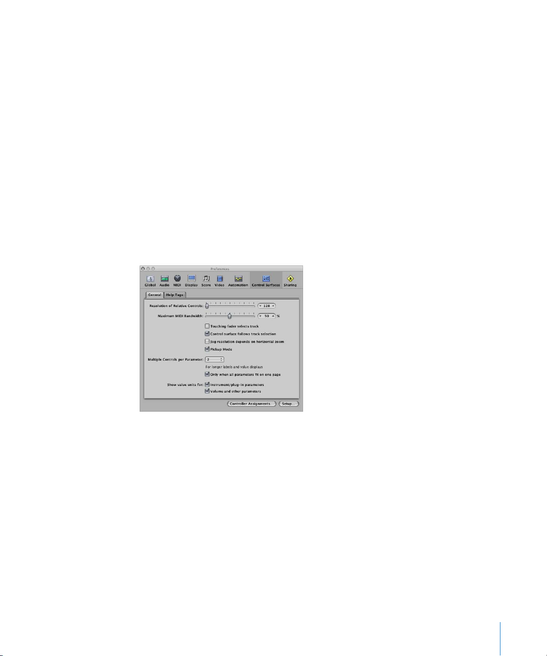
General Preferences
General control surface preferences include resolution of relative controls, maximum
MIDI bandwidth, and other functions.
 Resolution of Relative Controls slider: Sets the resolution of controls that change
values in a relative manner. The default resolution is 128 steps. Choose a higher
resolution value to divide the value range into finer increments.
 Maximum MIDI Band Width slider: Drag to set the maximum amount of MIDI
bandwidth that your control surface can use. This is set to a default of 50%, which
should be suitable for most situations. You can adjust the value if you find that your
MIDI or automation playback is being affected.
 Touching fader selects track checkbox: When active, touching a fader on the control
surface selects the track corresponding to the fader. For this to work, the device must
feature touch-sensitive faders.
 Control surface follows track selection: When active, selection of a track in the Arrange
window will automatically select the corresponding track/channel on the control
surface.
Chapter 1 Basic Control Surface Setup 29
Page 30

 Jog resolution depends on horizontal zoom checkbox: When active, the precision of
scrubbing (using the jog/shuttle wheel of your control surface) is determined by the
horizontal zoom level of Logic Pro. Your control surface must feature a jog/shuttle
wheel (or similar control) for this to have any effect. To retain a consistent resolution,
regardless of Logic Pro window zoom levels, disable this checkbox.
 Pickup Mode checkbox: When active, the control surface operates in Pickup mode (if
this mode is available). Some control surfaces, typically those without motorized
faders or knobs, do not show parameter changes—caused by playing back existing
automation data—on their interface. Such control surfaces usually offer a pickup
mode. In pickup mode, the controller must reach (“pick up”) the current value before
the value starts to change. This prevents sudden jumps of parameter values caused
by playing back automation. Your device may feature a display (usually a pair of
arrow LEDs) that indicates the direction or distance you need to move the controller,
in order to match the settings shown in Logic Pro (also known as NULL). Once you
have matched the onscreen values, deactivate Pickup mode and start automating.
When Pickup mode is disabled, adjusting a fader modifies the parameter
immediately (which can result in parameter value jumps).
 Multiple Controls per Parameter pop-up menu: Choose the maximum number of
encoders used for each parameter, when editing plug-ins or audio instruments. The
choices are:
 1: Parameters are always displayed using one encoder per parameter, with the
least space available for parameter name and value in the LCD.
 2: On each unit, encoders 1 and 2 are used for the first parameter, encoders 3 and
4 for the second, and so on.
 4: On each unit, encoders 1 to 4 are used for the first parameter, encoders 5 to 8
for the second, and so on.
 8: On each unit, encoders 1 to 8 are used for the first parameter, encoders 9 to16
for the second, and so on.
When multiple encoders are used per parameter, the encoders are divided into
groups (1/2, 3/4, 5/6, 7/8, for example). The first encoder of each group controls the
parameter shown in the display. The remaining encoders are inactive.
Using more than one encoder per parameter shows fewer parameters at any given
time, but you gain space on the LCD to cater for longer parameter names and values.
The more control surfaces you have within a control surface group, the more you
benefit from this feature.
30 Chapter 1 Basic Control Surface Setup
Page 31
 Only when all parameters fit in one page: When turned on, the defined number of
encoders are only used when there are sufficient encoders available to show all
parameters, without changing pages. As an example, if you have a Mackie Control
and two Mackie Control XTs (giving you at total of 24 encoders), a plug-in with 13
parameters will be shown with one encoder per parameter. Eleven encoders will
remain unused. A plug-in with 11 parameters will be shown with two encoders per
parameter. Two encoders will remain unused (as will the inactive encoders of the
sub-divisions mentioned above).
When turned off, multiple encoders are used for each parameter, which may require
scrolling. This would not be the case if only one encoder was used for each
parameter.
 Show value units for: The two checkboxes in this section allow you to adjust whether
parameter values are appended by the measurement unit, where applicable—“Hz”
or “%,” for example. You can set this option separately for instrument/plug-in
parameters, and for volume and other channel strip parameters. When turned on,
applicable values are appended with the appropriate unit. Turn off if viewing units
makes the display too cluttered.
 Controller Assignments button: Click to open the Controller Assignments window.
 Setup button: Click to open the Control Surfaces Setup window.
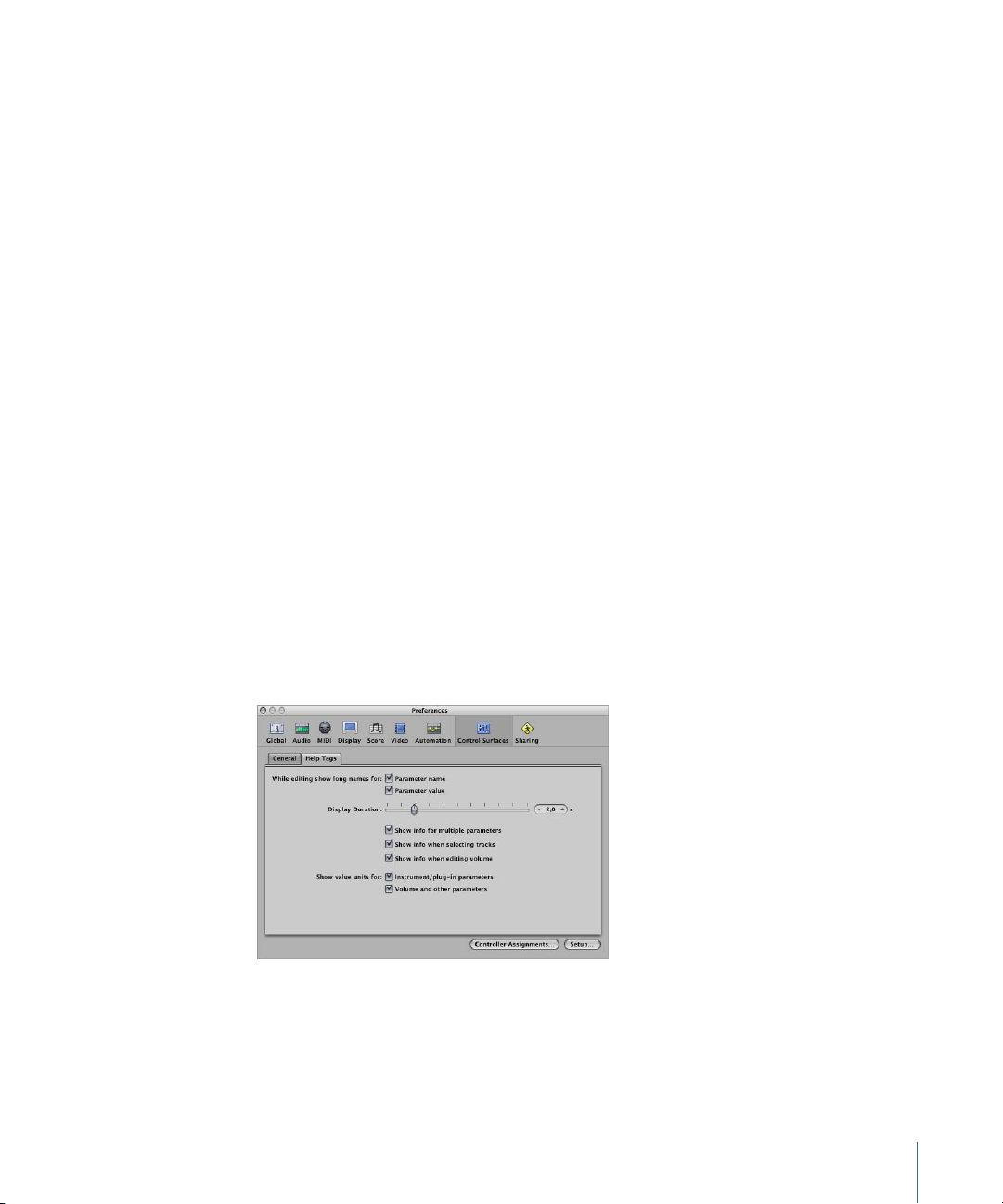
Help Tags Preferences
For control surfaces that feature freely programmable displays with more than six
characters per line (or segment) of the display, you can change the way help tags are
shown. Control surface help tags are similar to Logic Pro help tags, showing additional
information during use.
 While editing show long names for: The two checkboxes in this section allow you to
set how the names and values of parameters are displayed on the LCD of the control
surface.
Chapter 1 Basic Control Surface Setup 31
Page 32

 Parameter name checkbox: When turned on, the upper LCD line displays the full
parameter name, rather than an abbreviated form of it, when you edit a parameter,
 Parameter value checkbox: When turned on, the lower LCD line displays the full
parameter value when you edit a parameter. If the “Show value units for
parameter” boxes (see below) are checked, it will be appended by the
measurement unit, where applicable (as examples: “dB,” “Hz,” or “%”).
Note: The following options only have an effect if at least one of the two parameters
described above is active.
 Display Duration slider: Drag to adjust the time that parameter names and values
remain on the LCD display, following selection/adjustments.
 Show info for multiple parameters checkbox: When enabled: the long name info
appears in the display until the most recently edited parameter’s display times out.
This may cause overlapping text. When disabled: the long name display is only
shown for the most recently edited parameter, which can cause screen flicker.
 Show info when selecting tracks checkbox: When turned on, Selected appears in the
upper row of the LCD, and the selected track’s name is shown in the lower row, when
you select a track.
 Show info when editing volume checkbox: When turned on, the word Volume appears
in the upper row of the LCD, and the edited value appears in the lower row, when
you edit a track’s volume.
 Show value units for checkboxes: When turned on, parameter values are appended by
the appropriate measurement unit (“Hz” or “%,” for example). You can set this option
separately for “Instrument/plug-in parameters” and “Volume and other parameters.” If
you can do without value units, the display is less cluttered.
Note: This parameter only applies while you are editing the relevant values.
Modal Dialog Display
All modal dialogs (except File Open dialogs) appear on the LCD display of control
surfaces that feature text displays. Examples of modal dialogs include authorization
warnings, edit confirmations, or error messages. While a modal dialog is visible, you
cannot perform actions in any other window.
The modal dialog text appears in the upper row of the LCD. If the dialog text does not
fit in the LCD’s upper row, it starts scrolling after three seconds. You can scroll the
dialog text manually with the appropriate control (see assignment tables in the
appropriate chapter). Once you start scrolling the text manually, automatic scrolling is
disabled.
 If the control surface has an Enter or OK button, it triggers the dialog’s default
button, where applicable.
32 Chapter 1 Basic Control Surface Setup
Page 33

 If the control surface has a Cancel or Exit button, it triggers the button labeled Cancel
or Abort, where applicable.
 All buttons in the modal dialog (push buttons, including Enter/default and Cancel, as
well as checkboxes and radio buttons, but not pop-up menus) appear in the display’s
lower row.
Pressing a control surface button below the display triggers the appropriate function in
the dialog, if applicable. Once you press a Enter/Cancel button on the control surface or
click it onscreen, the dialog disappears, and all controls and displays return to their
previous state.
When an File Open dialog appears onscreen, the message There is a file select
dialog on the screen
one).
appears on the LCD or other display (if your control surface has
Usage Tips
You may find that using control surfaces changes the way you use Logic Pro, and you
can get the most effective use from them if you modify your working methods slightly.
The following collection of hints may help to smooth and streamline your Logic Pro/
control surface workflow.
Customize Your Templates
 Set up screensets 1–7 as your most frequently used screensets. You can access these
directly on some control surfaces (on a Mackie Control, for example, you can access
them with Function Keys F1 to F7, while Function Key 8 (F8) closes the top-most
window).
 It is recommended that you assign a full-screen Arrange window, with track
automation view set to on (for all tracks), as one of your screensets.
 A full-screen Mixer window is also recommended as another screenset.
Make Use of Markers
Markers allow you to quickly navigate from location to location in a project. Most
control surfaces feature a number of shortcuts that allow you to rapidly move between
markers, which is an extremely useful way of moving around in your projects.
Markers are also useful for the creation or selection of cycle areas and a number of
other tasks, such as punch and replace recording.
If you tend to follow a particular song structure, or like to work with a particular
number of bars (4, 8, 16 bars, and so on) for verse and chorus sections, then set up a
number of markers at suitable locations in your templates.
Chapter 1 Basic Control Surface Setup 33
Page 34

Page 35

2 Customizing Controller
Assignments
2
You can assign controllers to Logic Pro parameters, and edit
controller assignments to fit you workflow.
This chapter describes how to assign controllers to Logic Pro parameters, edit controller
assignments, and use zones and modes to switch between groups of assignments.
Assigning Controllers to Logic Pro Parameters
You can assign any controller that is capable of generating a MIDI message to a
parameter in Logic Pro. Assigning controllers to Logic Pro parameters lets you use
faders, knobs, switches, and other controllers to remotely control Logic Pro functions.
These can be used “as is,” or in conjunction with modifier keys.
Most supported control surfaces include preset controller assignments—which
become active as soon as you add the device to your system. You can change existing
assignments for supported control surfaces, and create new assignments for both
supported and unsupported devices. To provide you with an example: the default
assignments of the F1 to F8 buttons on the Mackie Control open screensets 1 to 8 in
Logic Pro. You can reassign these function keys to other commands—either alone or in
conjunction with the Command, Shift, Option, or Control keys—in any combination.
You can assign controllers to parameters in the Controller Assignments window, using
the Learn process. The Controller Assignments window has two views: a compact Easy
view, in which you can assign channel strip and plug-in parameters. The more extensive
Expert view enables you to create and edit any type of controller assignment, including
global, automation, and control surface group assignments.
35
Page 36

Working in Easy View
Easy view allows you to see, and assign, controllers to channel strip and plug-in
parameters, and to change the track that assignments apply to. Assignment of
controllers to channel strip and plug-in parameters is achieved through the Learn
process.
The Easy view of the Controller Assignments window contains the following fields and
buttons:
 Expert View button: Click to open the editor in Expert view.
 Back/Forward buttons: Click to move back and forth between assignments.
 Link button: When active, the assignment that matches the most recently received
MIDI message is automatically selected.
 Parameter field: Displays the name of the selected parameter.
 Channel Strip menu: Choose whether the assignment applies to the selected track, or
matches the channel strip number entered into the field beside the menu (as shown
in the Mixer’s All view).
 Input message field: Displays the incoming MIDI message data of the controller being
assigned to a function.
Only one set of assignment parameters is visible at a time.
To assign a controller in Easy view:
1 In the Mixer, or in any plug-in window, click the parameter that you want Logic Pro to
learn as a controller assignment.
2 Choose Logic Pro > Preferences > Control Surfaces > Learn Assignment for <parameter
name>. Alternately, you can use the Learn new Controller Assignment key command,
default: Command-L) to open the Controller Assignments window, and activate Learn
mode.
The Controller Assignments window opens in Easy view, with the Learn Mode button
activated. In most cases, the name of the clicked parameter is shown in the Parameter
field.
Note: The Controller Assignments window view mode is memorized. If the Expert view
was active when you closed the window, it will display the Expert view when reopened.
36 Chapter 2 Customizing Controller Assignments
Page 37

3 Move the controller you want to assign to the selected parameter.
Moving the controller sends a MIDI message to Logic Pro, which appears in the “Input
message” field. The Learn Mode button remains active, allowing you to make further
assignments.
4 To make another assignment, select the parameter you want to assign in Logic Pro,
then move the desired controller on the control surface.
5 When you have finished, click the Learn Mode button (or press Command-L) to
complete the Learn process, and exit learning mode.
An alternative learning method:
1 Press Command-L to open the Controller Assignments window.
2 Hold down the desired modifier (Command, for example) key as you click the
parameter you want to assign, while moving the control.
3 Click the Learn Mode button to complete the Learn process.
If Logic Pro receives a MIDI message from the device while you are holding down the
modifier key, releasing the key deactivates the Learn Mode button and completes the
Learn process. If you release the modifier key before Logic Pro receives a MIDI message,
the Learn Mode button remains active, so you can still move a controller to send a MIDI
message. In this situation, be sure to click the Learn Mode button when you are
finished—to end the Learn process.
To delete a controller assignment in Easy view:
m Choose the assignment you want to erase in the Controller Assignments window (Easy
view), and click the Delete button.
Assigning a Series of Controllers
Logic Pro includes a shortcut that makes it easy to assign a series of controllers to a
series of similar parameters. You can use this shortcut to assign a series of faders to
volume, or to assign a series of knobs to other channel strip parameters such as; pan,
solo, or mute, or to assign a series of controllers to a set of plug-in parameters:
To assign a series of controllers to a series of parameters:
1 Following the standard assignment procedure, assign the first controller in the series to
the first parameter (assign fader 1 to control volume for channel strip 1, for example).
2 Assign the last controller in the series to the last parameter (assign fader 16 to control
volume for channel strip 16, for example). The number of controllers between the first
and last in the series must match the number of parameters between the first and last
parameter.
A “Do you want to fill up in between?” dialog is shown.
Chapter 2 Customizing Controller Assignments 37
Page 38

The dialog appears when the distance between the last two controllers matches the
distance between tracks (or the number of parameters between the last two assigned,
if dealing with plug-in parameters). In the above examples, the distance between 1 and
16 would equal 15.
3 Click OK to automatically fill the controllers between the first and last—with the
corresponding assignments.
Parameter assignment numbering (for plug-ins) is shown in the Plug-in window’s
Control view.
Note: You can only use shortcuts for knobs that send a single channel message, where
the first data byte is the controller number and the second data byte is the value.
Alternatively, the controller number can be encoded in the MIDI channel, with a fixed
first data byte. Consult the documentation that came with your device for information
on its data structure.
Working in Expert View
You can make use of Expert view to make advanced controller assignments. This
includes Logic Pro parameters other than channel strip and plug-in parameters. As
examples, you can assign controllers to global, automation, and control surface group
parameters in Expert view. You can also extensively edit controller assignments in
Expert view, and define zones and modes, which let you switch between groups of
controllers.
The Learn process opens the Controller Assignments window in Easy view, which
shows the basic parameters for the current assignment. To make assignments other
than channel strip or plug-in assignments (or to edit other assignment parameters),
you need to switch to Expert view.
∏ Tip: You can only switch back to Easy view if a track or plug-in parameter is selected.
38 Chapter 2 Customizing Controller Assignments
Page 39

To open the Controller Assignments window in Expert view:
m Click the Expert view button.
In Expert view, the Controller Assignments window contains the following fields,
menus, and buttons—used to edit assignment parameters, and define zones and
modes.
 Zone list: Displays the available zones for the device. The first entry “(No Zone)” is for
zoneless assignments—assignments that are always active, regardless of the active
zone. Click a zone in the list to see its modes (in the Mode list), and its current
assignments (in the Control/Parameter list). You can also double-click a zone to
rename it.
 Mode list: Displays the modes for the currently selected zone. The first entry “(No
Mode)” is for modeless assignments. Click a mode in the list to see its assignments in
the Control/Parameter list, and make it the selected zone’s active mode. You can also
double-click a mode to rename it.
 Control/Parameter list: Select the assignment you want to edit. The left column
displays the name of the control, and the right column displays the name of the
parameter being controlled (in an abbreviated form). The parameters of the selected
assignment appear in the fields to the right of the list. See “Controller Assignment
Parameters” on page 40.
Note: You can select multiple assignments in the list, but only the parameters of the
first selected assignment are displayed. When multiple assignments are selected:
operations performed in the Edit menu can be applied to all selected assignments. All
other operations only apply to the first assignment.
 Controller Assignment Parameter: All aspects of the selected controller assignment
parameter are shown—and can be changed—in this area.
Chapter 2 Customizing Controller Assignments 39
Page 40

 Input Message: The port and MIDI input message can be altered directly. Some fields
in this section are merely displays, and cannot be changed.
 Value: The range of values, and response, of the controller assignment to incoming
messages is determined in this area. Feedback to the display of control surfaces can
also be determined here.
Controller Assignment Parameters
This section outlines each parameter shown in the right-hand fields of the Expert view.
Detailed descriptions of each parameter can be found in “Editing Controller
Assignments in Expert View” on page 44.
Controller Assignment Parameter Section
 Control name field: Displays the name of the controller for supported devices. For
unsupported devices, displays Learned.
 Label field: Displays characters which represent the label for the assignment on the
control surface’s display. You can view this much like a scribble strip on a mixer.
 Flip Group field: Enter an integer to define a flip group for the assignment.
 Class pop-up menu: Choose the class of parameter (parameter type) you want to
assign.
Note: Depending on the class you choose, different fields and menus for that class
appear below the Class pop-up menu. See below:
 Parameter/Mode pop-up menu/field: Dependent on your selection in the Class pop-
up menu, you can choose from dozens of different parameters/modes. The options
available will change as different classes are selected.
 Group/Track/Command/Key field/menu: These options will also change as different
Class menu options are selected.
 Bank Type pop-up menu: This menu determines the bank relationship of the assigned
parameter. This can be as per the Group setting, By One or By Bank.
Input Message Section
 MIDI Input pop-up menu: Choose a MIDI input source (MIDI Port or Caps Lock
Keyboard). This can be changed by incoming MIDI messages—shown in the Value
Change field.
 Value Change field: Displays incoming MIDI messages that cause a value change.
 Touch/Release field: Enter an integer value to force incoming MIDI messages to
change the touch/release status of the selected parameter. This only applies to
control surfaces that offer touch-sensitive controls—where touching or releasing a
fader, for example, will enable/disable the reception of data from the control surface.
40 Chapter 2 Customizing Controller Assignments
Page 41

Value Section
 Min and Max fields: Enter integer values—to set the range of incoming MIDI values.
 Format pop-up menu: Choose the format used to encode negative values.
 Multiply field: Enter a value—which will scale incoming MIDI values.
 Mode pop-up menu: Choose the mode used by incoming values—to modify the
current parameter value.
Feedback pop-up menu and checkboxes: Choose the display format of the parameter
value (on the control surface display, if applicable).
Note: For detailed information about each parameter, see “Editing Controller
Assignments in Expert View” on page 44.
Assigning Controllers in Expert View
Expert view allows you to assign controllers as you would in Easy view—using the
Learn process. You can also (manually) assign controllers to classes of Logic Pro
parameters that are not accessible in Easy view.
To assign a controller to a non channel strip or plug-in parameter:
1 Open the Controller Assignments window in Expert view.
2 Choose the desired zone and/or mode (unless you want to make a modeless
assignment), and click the plus button at the lower-left corner of the Control/Parameter
list.
A new, blank assignment appears in the Control/Parameter list.
3 Click the Learn Mode button to start the Learn process.
4 Move the controller you want to assign to the selected parameter.
Moving the controller sends a MIDI message to Logic Pro (thus “teaching” Logic Pro
which controller you are assigning). The MIDI message appears in the Input message
field. The Learn Mode button remains active, allowing you to make further
assignments.
5 Once Logic Pro has received the message, choose the class of parameter you want to
assign from the Class pop-up menu.
6 Assign the parameter by making appropriate choices in the menus and fields that
appear below the Class menu.
Note: A detailed explanation of classes and other assignment parameters can be found
in “Editing Controller Assignments in Expert View” on page 44.
7 When you are finished, click the Learn Mode button (or press Command-L) to complete
the Learn process.
You can use the shortcut—described in “Assigning a Series of Controllers” on
page 37—to assign a series of controllers to a series of similar parameters.
Chapter 2 Customizing Controller Assignments 41
Page 42

To delete an assignment in Expert view:
1 Select the assignment that you want to delete in the Control/Parameter list.
2 Choose Edit > Delete in the main menu bar (or press the Backspace key).
About Zones and Modes
You can define a group of controllers as a zone in Expert view, and switch all controls in
a zone to different parameters—in one operation. Using a Mackie Control as an
example; you can define the eight rotary encoders as a zone, and switch them between
pan, send level, or plug-in parameters. You can define multiple zones for a control
surface: one for the encoders, and a second one that switches the function keys (F1 to
F8) to different functions, for example.
Each set of zone parameters is called a mode. A zone can contain one or more modes.
Only one mode can be the active mode at any given time. A zone can also contain
assignments which are always active, regardless of the active mode (these are known
as modeless assignments).
The simultaneous use of modal and modeless assignments allows you to do things
such as:
 Define a zone that switches between two modes (or functions) by pressing/releasing
the Option button while using a particular Function key.
 Define a zone that allows you to use modeless assignments for things like updating
the display, Transport functions, and Save or Undo operations. The same zone could
contain a modal assignment for all Volume and Pan controls. Switching to another
mode would provide access to EQ parameters. In both modal situations, the display,
Transport and Save/Undo functions would be available.
A mode can contain any number of assignments. Only the assignments for the active
mode are processed by Logic Pro. Assignments of inactive modes are ignored.
You can switch the active mode for a zone by special assignments (see below).
Zones and modes can be defined across multiple control surfaces, to support the use
of control surface groups.
42 Chapter 2 Customizing Controller Assignments
Page 43
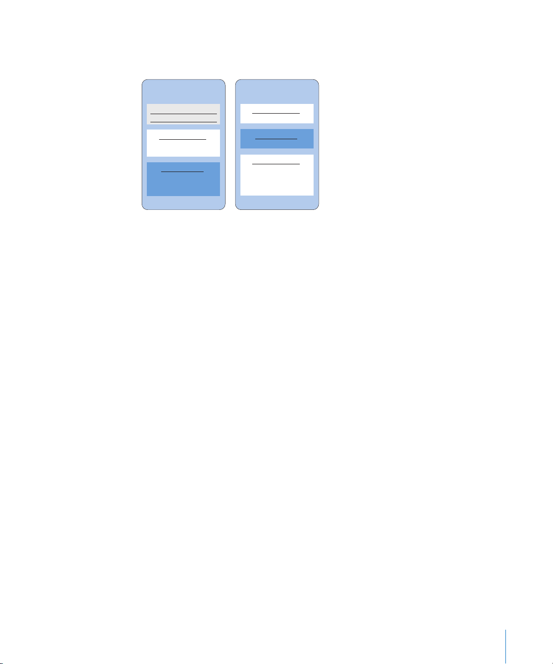
The following list illustrates one possible arrangement of zones and modes, which
shows how you can define them, hierarchically:
Zone 1 Zone 2
Modeless Assignment A
Modeless Assignment B
Mode 1 (inactive)
Modal Assignment A
Modal Assignment B
Mode 2 (active)
Modal Assignment A
Modal Assignment B
Modal Assignment C
Mode 3 (inactive)
Modal Assignment A
Mode 4 (active)
Modal Assignment A
Mode 5 (inactive)
Modal Assignment A
Modal Assignment B
Modal Assignment C
Modal Assignment D
Defining Zones and Modes
You can only define Zones and Modes in the Expert view.
To define a zone:
1 Click the Add button at the lower-left corner of the Zone list.
A new, blank zone appears in the Zone list. It is highlighted, allowing you to
immediately rename it.
2 Type a name for the zone.
If you would like to add controllers to a zone, see “Assigning Controllers in Expert View”
on page 41.
To define a mode:
1 Click the Add button at the lower-left corner of the Mode list.
A new, blank mode appears in the Mode list. It is highlighted, allowing you to
immediately rename it.
2 Type a name for the mode.
If you would like to add controllers to a mode, see “Assigning Controllers in Expert
View” on page 41.
Chapter 2 Customizing Controller Assignments 43
Page 44

Reassigning a Controller
The procedure for reassigning an active controller (an assigned controller in the active
mode) is different to that for an inactive controller (one with an assignment in a non
active mode).
Reassigning an Active Controller
When you use the Learn process to assign an active controller (one with an assignment
in the active mode), a dialog is shown:
 Cancel: Deletes the new assignment, retaining the existing assignment.
 Keep both: Retains the new and old assignments. Typical usage: one knob controls
multiple parameters—as a macro.
 Reassign: Deletes all existing active assignments for this parameter. Typical usage:
reassigning a function key (F1 to F8, for example) to a new key command.
Reassigning an Inactive Controller
When you use the Learn process to assign a controller in an inactive mode, the new
assignment becomes part of the active mode—in the zone that contained the
previous, inactive assignment.
This is typically used as follows: Supported control surfaces generally have empty user
pages available, allowing for new encoder assignments. You would select a particular
user page mode (page 3, for example), and then learn an assignment for the encoder.
Editing Controller Assignments in Expert View
You can edit the following parameters for the selected assignment, in the fields to the
right of the Controller Assignments window.
Control Name Field
Shows the name of the control. For supported devices, the control surface name is
used. For assignments created with the Learn process on unsupported control surfaces,
the control name defaults to Learned. You can enter a new name in the field. The
control name is for display only, and has no effect on functionality.
44 Chapter 2 Customizing Controller Assignments
Page 45

Label Field
For supported control surfaces, shows characters that represent the label for the
assignment that appears on the control surface display. Unsupported control surfaces
can only send information, not receive it, and cannot display an assignment label.
If the field contains constant text, it can contain any number of characters. When used
as a placeholder for dynamically created text, however, the field contains three
characters that represent the label. The first character is always @, followed by two
additional characters. The following tables show the possible meanings for the second
and third characters.
Second Character
Character Meaning
t Track
r Surround
s Send slot
S Number of sends
e EQ band
E Number of EQs
p Insert slot
i Instrument
Third Character
Character Meaning
# Number of above (track number, Send slot, EQ band, Insert slot)
n Name of above
p Name of parameter addressed by the assignment
P Name of first parameter
o Parameter offset, counted from 1
O Maximum parameter offset, counted from 1
b Parameter bank (= parameter offset/bank size), counted from 1
B Total number of banks (= parameter offset/bank size), counted
from 1
For example, “Send@s#” translates as “Send1,” “Send2,” and so on.
Chapter 2 Customizing Controller Assignments 45
Page 46

Flip Group Field
Enter the same integer value for two assignments, to define a counterpart for Flip
mode (for supported control surfaces that offer Flip mode). By setting a fader and an
encoder to the same flip group, for example, they are coupled. To set “none” enter a
value of 0.
For unsupported devices: you need to set up two active assignments, which both use
the same flip group; one assignment needs to be absolute (using a fader, for example),
the other relative (encoder, for example).
Exclusive Checkbox
When selected, the assignment will deactivate all other assignments that have
Exclusive disabled for the same control (on supported control surfaces). This limits the
overwriting of a modeless assignment to particular modes. To provide you with an
example: Faders normally control volume. To create a mode where faders control the
send level, enable Exclusive.
Class Menu
Choose the class of assignment (the type of destination parameter controlled) from the
menu. Different options appear below the Class pop-up menu when you choose a
class. The following section describes the different classes, and the options for each.
Mode Change
Choosing the Mode Change class lets you use an assignment to switch from one mode
to another. An additional Mode pop-up menu appears below the Class menu, allowing
you to choose between available modes. For example: The assignment buttons on a
Mackie Control can be used to choose different modes for the encoders.
Note: The mode chosen in the Mode menu is only activated when the Value section:
Mode menu is set to Direct.
If any of the other Value section: Mode menu options is chosen, the following applies:
 Toggle: The assignment toggles between the zone’s first mode and the chosen
mode. The mode change assignment must be located in the same zone.
 Relative: Useful for stepping up and down through modes in a zone—using two
buttons—or for choosing a mode with an encoder. The minimum destination
parameter represents this zone’s first mode, and the maximum represents the zone’s
last mode. The mode change assignment must be located in the same zone.
 Rotate: Useful for stepping through all modes with a single button. A jog wheel, for
example: Off → Scrub → Shuttle → Off. The minimum destination parameter
represents this zone’s first mode, and the maximum represents the zone’s last mode.
The mode change assignment must be located in the same zone.
46 Chapter 2 Customizing Controller Assignments
Page 47

Global
Choosing the Global class lets you use an assignment to control global parameters. A
Parameter pop-up menu appears below the Class menu, offering the parameters listed
in the following table.
Global Options Explanation
Playhead This assignment controls the position of the playhead; Feedback is sent in the
format chosen in the control surface group’s Clock Display parameter.
Playhead (Beats) As above, but feedback is sent in beats format.
Playhead (Time
Code)
Playhead (Beats,
Scrubbing)
Move Locators Moves left and right locators.
Left Locator Sets left locator.
Right Locator Sets right locator.
Move Punch
Locators
Punch In Locator Sets punch in locator.
Punch Out Locators Sets punch out locator.
Marker Position Edits position of current marker.
Marker Length Edits length of current marker.
As above, but feedback is sent in SMPTE time code format.
Moving the controller doesn’t set the playhead position, but initiates
scrubbing. The format is defined by the control surface group format
parameter. The controller value defines the scrubbing speed.
Moves punch in and punch out locators.
Note: All options listed in the table above only work in relative mode—where changes
are relative to the starting value/position and so on. See the “Clock Part” sub-parameter.
Global Options Explanation
Nudge selected
Regions/Events
Any Solo Feedback only. On if any (track or region) Solo button is active
Nudge Value Controls the nudge value used for Nudge selected Regions/Events. Switches
Scrub Status Sets the scrubbing status for the Playhead parameter (beats, scrubbing).
Automation of all
tracks
Alert Text, Alert
Button, Alert Icon
Dummy Used to temporarily disable a modeless assignment, by using the Exclusive
Cycle Toggles the Cycle function on and off.
Chapter 2 Customizing Controller Assignments 47
Nudges the selected regions or events by the chosen nudge value (see below).
between tick, division, beat, bar, frame, 1/2 frame.
Possible values are: set clock, audio scrubbing, shuttle.
Switches the automation status of all tracks between the following values: off,
read, touch, latch, write.
Used by plug-ins to define special alert mode. This is mainly of use to control
surface developers.
checkbox. See “Exclusive Checkbox” on page 46.
Page 48

Global Options Explanation
Autopunch Toggles the Autopunch function on and off.
Go to Marker Allows you to move the playhead to a marker number. An additional number
field below the Parameter menu is used to determine the destination marker
number.
Group Clutch Sets the automation group clutch; Automation groups are disabled when the
clutch is enabled. For buttons, set the group clutch to 1 when the button is
pressed, and set it to 0 when the button is released.
Active Sense Used by some control surfaces (such as the HUI) to process incoming Active
Sensing messages.
Shuttle Speed Sets the shuttle (forward and backward) speed directly. Use this for controllers
(usually knobs) that send an absolute—not relative—value.
Waveform Zoom Sets the waveform zoom level in the key focus Arrange area.
Quantize value Sets the Quantize value in the key focus window (if this parameter is available).
Division Sets the Division value in the key focus window (if this parameter is available).
Horizontal Zoom Sets horizontal zoom in the key focus window (if this parameter is available).
Vertical Zoom Sets vertical zoom in the key focus window (if this parameter is available).
Channel Strip
Choosing the Channel Strip class lets you use an assignment to set a channel strip
parameter. A Channel Strip pop-up menu appears below the Class menu, offering the
following parameters.
Channel Strip Type Explanation
Selected track This normally corresponds to the selected Arrange track. Exception: If the
control surface group’s Track Lock parameter is enabled, the selected track is
the one that was selected when Track Lock was enabled
Fader Bank This addresses a channel strip in the control surface group’s current View mode
(Arrange, All, Tracks, Single). This is dependent on the current Fader Bank value
for this mode (see below).
Example: The View mode is All, the All view Fader Bank is five, and the number
next to this parameter is two. Thus, the eighth channel strip in the All view is
addressed (Fader Bank and No. are 0-based, so add 1).
Index Same as the Fader Bank setting, but doesn’t depend on the current Fader Bank
value.
Audio An audio channel. The numerical value (No.) determines which audio channel
is addressed (again: 0-based; to address audio channel 2, use a value of 1).
Software Instrument Same as Audio setting, for software instrument channel strips.
Bus Same as Audio setting, for bus channel strips.
Auxiliary Same as Audio setting, for auxiliary channel strips.
Output Same as Audio setting, but for output channel strips.
Master The Master channel strip; If it does not exist in the project, the first output
channel strip is addressed.
48 Chapter 2 Customizing Controller Assignments
Page 49

If you choose the Fader Bank, Index, Audio, Software Instrument, Bus, Auxiliary, Output,
or Master setting in the Channel Strip pop-up menu, the following two parameters
become available:
 Number field: A 0-based offset, which is added to the channel strip number. The
typical use for this field is for sequential controls: Fader 1 uses offset 0, Fader 2 uses
offset 1, and so on.
 Parameter field: Text description of the addressed parameter. Can only be set by
choosing the Logic Pro > Preferences > Learn Assignment for <parameter name>
menu item. Note that for plug-in and instrument parameters, Parameter Page offsets
apply, allowing you to shift the parameter addressing up and down by page.
Key
Choosing the Key class lets you use assignments to emulate keystrokes on your
computer keyboard. You can enter the key to emulate in the Key field, which appears
below the Class menu. This is not case-sensitive.
Key Command
Choosing the Key Command class lets you use an assignment to perform a key
command. You can enter the desired key command in the Command field, which
appears below the Class menu. Some key commands provide on/off or enabled/
disabled feedback.
If you want your key command assignment to be executed repeatedly, select the Key
Repeat checkbox at the bottom of the Controller Assignments window. For further
information, see “Key Repeat Checkbox” on page 54.
Click the Show button to open the Key Commands window. The key command shown
in the Command field is automatically selected/shown in the Key Commands window.
Control Surface Group
Choosing the Control Surface Group class allows you to set a property for the control
surface group (that the assignment belongs to). When you choose this class, a
Parameter menu appears below the Class menu. This menu allows you to choose one
of the options described in “Control Surface Group Parameters” on page 23, or one
from those listed in the following table.
Chapter 2 Customizing Controller Assignments 49
Page 50

Note: Assignments for unsupported control surfaces always belong to the first control
surface group.
Parameter Option Additional Info
Fader Bank for Current
View
Filter for All View When this parameter is selected, eight additional checkboxes—for the
Fader Bank for:
MIDI Channel Strips
Input Channel Strips
Audio Channel Strips
Instrument Channel Strips
Aux Channel Strips
Bus Channel Strips
Output Channel Strips
Maps to the fader bank for the currently used View mode. This way, you
need only one assignment per left/right button for all View modes.
eight channel strip types—are displayed, when the View mode is All.
Depending on the Value Mode, these switches define which channel
strips are displayed (by using Direct mode) or which are toggled (by using
X-OR mode).
These fader bank parameters are used in All View—when only one
channel strip type is displayed. This allows you to switch between several
channel strip types, while retaining the current fader bank for each type.
If you choose one of the fader bank or parameter page settings in the Parameter menu,
the following Bank Type options appear below the menu.
 By One: The fader bank or parameter page is shifted by one channel strip or
parameter.
 By Bank: The fader bank or parameter page is shifted by the number of displayed
channel strips or parameters.
 CS Group Setting: The fader bank or parameter page is shifted by the value defined
for the Parameter Page Shift Mode control surface group parameter.
Automation Group
Choosing the Automation Group class allows you to use the assignment to set an
automation group parameter.
When this class is chosen, a Group field appears below the Class menu. You can
determine the edited group by entering a number in the field. Entering a “0” sets this
parameter to the group selected for the Automation Group parameter (in the control
surface group parameters).
A Parameter menu also appears below the Group field, allowing you to choose the
automation group parameter for the assignment. For further information, see the
Group Settings section of the Logic Pro 8 User Manual.
50 Chapter 2 Customizing Controller Assignments
Page 51

Input Message Section
The parameters in this section let you control different aspects of MIDI input.
MIDI Input Pop-up Menu
When you choose a MIDI input (port) from the menu, all assignments that use the
same input are changed accordingly. If the assignment belongs to a supported control
surface, the device’s MIDI Input also changes in the Setup window.
This makes it easy for you to create default assignments for a new control surface.
These new assignments can be moved to other machines by copying your
com.apple.Logic.cs preferences file. Simply paste this preference file into the
Preferences folder of another machine, open the Controller Assignments window in
Expert view, and change the MIDI Input parameter of one assignment (as applicable to
the MIDI setup on the other machine).
Value Change Field
Shows incoming MIDI messages that cause a value change in the destination
parameter, and lets you edit these MIDI messages.
The Value Change field displays the message as a sequence of hexadecimal bytes. The
plain language meaning appears below the field. The placeholders for the variable part
of the message are:
 Lo7: Low 7 bits of the value (LSB or Least Significant Bits)
 Hi7: High 7 bits of the value (MSB or Most Significant Bits)
For messages containing only a Lo7 placeholder the value is treated as 7-bit. For
messages containing both a Lo7 and Hi7 placeholder, the value is treated as 14-bit. The
order of Lo7 and Hi7 is honored, and there may be constant bytes in between. This
allows you to define Control Change LSB and MSB portions. For example: B0 08 Hi7 B0
28 Lo7 indicates a 14-bit message.
Note: When you enter multiple MIDI messages, always enter each message completely,
being sure to repeat the status byte, even if it’s the same. It may help to write out the
message—to ensure that the correct byte works, as you can’t know what status the
previously sent message had.
For messages containing neither Lo7 or Hi7 placeholders, Logic Pro assumes an
incoming value of 1. This is typical for pressed or released buttons. Also see the Multiply
Field (p. 52) section below.
Touch/Release Field
Enter an integer value to use the incoming MIDI message for status changes of the
destination parameter—from touched to released, or vice versa. A non-zero value
means touched; a value of 0 means released. The messages are shown and edited in
the same way as the Value Change field (see the Value Change section above).
Chapter 2 Customizing Controller Assignments 51
Page 52

Note: This only applies to the Channel Strip assignment class, and to parameters that
can be automated.
Value Section
The parameters in this section let you control different aspects of the values for
incoming MIDI messages.
Min and Max Fields
Enter an integer value to set the minimum and maximum range for incoming values
represented by Lo7 and Hi7. Typically, the minimum defaults to 0, and the maximum
defaults to 127. Some control surfaces (such as the CM Labs Motor Mix) may use the
same message—with different value ranges—for different controls. For more specific
information, refer to the documentation of your device.
Format Pop-up Menu
Choose the encoding format for negative values in the 7-bit portions sent over MIDI.
The choices are:
 Unsigned: No negative values are possible. The full 7 or 14-bit range is treated as a
positive number. The value range is 0 to 127 (7-bit) or 0 to 16383 (14-bit).
 2's complement: If the most significant bit is set, the value is negative. To obtain the
absolute value, invert all bits and add 1. The value range is from –128 (7-bit) to 127 or
–8192 to 8191 (14-bit).
 1's complement: If the most significant bit is set, the value is negative. To set the
absolute value, invert all bits. Note that this allows two possible encoding values for
zero. The value range is –127 to 127 (7-bit) or –8191 to 8191 (14-bit).
 Sign Magnitude: If the most significant bit is set, the value is negative. To set the
absolute value, clear the most significant bit. Note that this allows two possible
encoding values for zero. This results in a value range of –127 to 127 (7-bit) or –8191
to 8191 (14-bit).
The appropriate format for a device is usually specified in its documentation. If
unavailable, check the control surface manufacturer’s website or contact them for more
information.
Multiply Field
Enter a scaling value for incoming values. This is especially useful for button presses
that have a value of 1. As examples:
 To set the automation mode to Write, set Multiply to 4.00, and Mode to Direct.
 To decrement a parameter by 1 with a button press, set Multiply to –1.00, and Mode
to Relative.
52 Chapter 2 Customizing Controller Assignments
Page 53

Mode Pop-up Menu
Choose the mode used by incoming values—to modify the current parameter value.
The choices are:
 Direct: The incoming value is used as the parameter value.
 Toggle: If the parameter’s current value is 0, it is set to the incoming value. All other
values set the parameter value to 0. This option is useful for buttons which toggle a
value: Mute, Solo, and so on.
 Scaled: The incoming value is scaled; from its value range to the destination
parameter’s value range. This is useful for faders and rotary encoders.
 Relative: The incoming value is added to the parameter’s current value. Used by
encoders, but also for buttons that increment/decrement by a certain amount (set by
the Multiply parameter).
 Rotate: The incoming value is added to the parameter’s current value—cycling
between maximum and minimum values. This is useful for button presses that cycle
between modes: automation mode, for example.
 X-OR: The value defines a bit mask (a filter, in other words), which is applied to the
parameter’s current value with the “exclusive or” Boolean operation. Useful for
enabling/disabling single channel strip types in All view.
For On/Off parameters, Mode is set to Toggle by default. It is set to Scaled for absolute
controls (faders and pots, for example), or to Relative for encoders.
Feedback Pop-up Menu
Choose the display format for the parameter’s current value (on the control surface
display). The choices are:
 None: No feedback is sent.
 Single Dot/Line: LED rings: only one LED; LCDs: a single vertical line.
 Left to Right Bar: A bar from the minimum to the current value.
 Bar from Center: A bar from the center position to the current value.
 Right to Left Bar: A bar from the current value to the maximum.
 Q/Spread: Two equal bars from the center to the current value.
 Ascending Bar: A bar from the bottom to the current value.
 Descending Bar: A bar from the top to the current value.
 Text Only: LED rings: no feedback; LCDs: no feedback as a graphic element.
 Automatic: Dependent on the currently assigned parameter, the most suitable
feedback mode is used: Plug-in and Instrument parameters carry this information,
Pan uses Single Dot/Line, all other parameters use Left to Right Bar.
Note: Feedback only works for supported control surfaces, and not all settings are
available for all controls.
Chapter 2 Customizing Controller Assignments 53
Page 54

Text Feedback Checkbox
When selected, a text representation of the current value is sent to the control surface’s
display. The control surface display facilities determine the display position and number
of characters that are used.
Local Feedback (Fader/Knob) Checkbox
When selected, no feedback is sent while the parameter is in Touched mode. This
prevents motorized faders from “fighting” against the user.
Key Repeat Checkbox
When selected, the assignment is repeatedly executed. The Key Repeat Rate slider—set
in the Mac OS X Keyboard & Mouse preferences—determines how quickly Logic Pro
repeats the assignment. The duration that the button/controller must be held for,
before the assignment is repeated, is set with the Delay Until Repeat slider in the
Keyboard & Mouse preferences.
Example: This facility is particularly useful for the zoom function: If you assign a key
repeat command to the Zoom buttons on the Mackie Control, you can simply hold
down the Zoom In button. Logic Pro will zoom in until the Zoom In button is released.
This mirrors the behavior of the Zoom key commands. The alternative would be
repeated presses of the (Mackie Control) Zoom buttons to zoom in/out more than one
level.
Note: The Key Repeat checkbox is only available for key commands, key presses, and
relative value changes. If any other assignment class is selected, the checkbox is
dimmed.
The default key command assignments support the Key Repeat function (if useful and/
or applicable to the control surface/device)—making changes unnecessary for use of
this functionality.
If you want to enable the Key Repeat function for your own assignments, you may
need to use the re-learn option for the assigned message. Key Repeat messages must
include the Lo7 byte, which provides information on the up (released) or down
(pressed) state of the assigned button.
Logic Pro guides you through the re-learning process: The current MIDI message is
automatically cleared, Learn mode is activated, and a help tag prompts you to send the
desired MIDI message.
Releasing the assigned button—after learning the MIDI message—automatically
creates the Lo7 byte, and assigns the Lo7 value (for the button release message) to the
Min parameter. The Lo7 value for the button pressed message is automatically assigned
to the Max parameter.
54 Chapter 2 Customizing Controller Assignments
Page 55

Typically, the value range of 1 to 127 is used for the button pressed message. The zero
(0) value is generally used for the button released message.
Note: Some control surfaces may use different value ranges (CM Labs MotorMix, for
example). Assigning appropriate Min and Max values ensures that key repeat will work
with such devices. This, however, means that you need to take care when manually
changing the Min or Max value for a key command (in cases where the Min and Max
values do not match the button pressed (on) and button release (off) states, the
complete assignment will not work). Please consult your control surface manual for
further information about the values it uses.
Assigning Buttons to Key Commands
In addition to assigning controllers to parameters, you can assign control surface
buttons—and button or key release messages—to key commands.
To assign a control surface button to a key command:
1 Choose Logic Pro > Preferences > Key Commands to open the Key Commands window.
2 In the Command list, click the disclosure triangle next to the desired category to reveal
the commands for that category, then select the key command you want to assign. You
can also search for the desired key command by in the Search field.
3 Click the Learn New Assignment button.
4 Press the (control surface) button that you want to assign to the key command. This
sends a MIDI message to Logic Pro.
The name of the controller appears in the Assignments field.
Chapter 2 Customizing Controller Assignments 55
Page 56

5 You can repeat steps 2 to 4 to make additional assignments, if desired.
6 When you are finished, click the Close button to exit the window.
To assign a button or key release message to a key command:
1 Choose Logic Pro > Preferences > Key Commands to open the Key Commands window.
2 In the Command list, click the disclosure triangle to reveal the commands for a
category, then select the key command you want to assign (or use the Search field).
3 Press—and hold—the (control surface) button or key that you want to assign to the
key command.
4 Click the Learn New Assignment button.
5 Release the button or key.
The name of the button or key appears in the Assignments field.
6 When you are finished, click the Close button to exit the window.
To delete a key command assignment:
1 In the Key Commands window, select the key command (with an assignment that you
want to delete) in the Command list.
2 Select the assignment for the key command in the Assignments field.
3 Press the Backspace key.
Controller Assignments Storage
The current controller assignments and all Control Surfaces preferences are stored in
the ~/Library/Preferences/com.apple.Logic.pro.cs file.
You do not need to specifically save controller assignments or related preferences and
settings. These are automatically stored (in the location mentioned above) when you
exit Logic Pro.
56 Chapter 2 Customizing Controller Assignments
Page 57

3 Mackie Control
3
You can fully control Logic Pro with a Mackie Control, and can
extend its functionality with several expansion devices.
The information in this chapter applies to the Mackie Control Universal, the original
Mackie Control, the Logic Control, and the Mackie (or Logic) Control Extender (XT). The
term Mackie Control is used for all of these devices throughout the chapter.
The controls of the Mackie Control are physically grouped into different areas, called
zones. Each zone is clearly labeled, and distinguished by different shades of gray on the
device. The following descriptions of Mackie Control features and functions is
organized by these zones.
Setting Up Your Mackie Control
When you open Logic Pro, it automatically detects any powered Mackie Control unit
that is connected to your system. You can use the Mackie Control immediately—with
the default settings—or can customize settings, as described in “Basic Control Surface
Setup” on page 15, and in “Customizing Controller Assignments” on page 35.
Using the Mackie Control With Logic Pro
There are many ways that you can use the Mackie Control in Logic Pro.
One simple workflow example involves the following steps:
1 With your project open in the Arrange window, select the channel strips you want to
control by pressing the Fader Bank buttons on the Mackie Control. See “Fader Bank
Zone” on page 79 for more information.
2 Select the parameters you want to edit, and whether you want to edit multiple
channels (Mixer view) or a single channel (Channel view), using the Assignment
buttons. See “Assignment Zone” on page 64 for more information.
3 Start playback, and move the playhead to the position where you want to work, using
the Mackie Control Transport buttons and Jog Wheel. See “Transport Zone” on page 86
and “Jog/Scrub Wheel Zone” on page 94 for more information.
57
Page 58

4 Edit the project with the channel strip controls. See “Channel Strip Controls” on page 61
for more information.
Display Zone
The display zone, located along the top of the Mackie Control, features four displays.
Each shows different information:
 Main Liquid Crystal Display (LCD)
 Assignment display
 Time display
 Solo LED
Main Liquid Crystal Display (LCD)
The main LCD is divided into eight sections (or columns, if you prefer), each with two
lines of text. Each section displays information for the channel strip controls directly
below it. The information displayed on the main LCD changes—dependent on the
parameters you are editing—and whether Mixer view or Channel view is active. In
general, the upper row of each section displays the (abbreviated) track (or channel)
name, and the lower row displays the (abbreviated) parameter name and/or its value.
In some modes, a long parameter name (or other text) appears briefly onscreen while
you are moving the corresponding control. You can set the display and duration of long
parameter names in the Control Surfaces preferences. For information on setting
preferences, refer to “Basic Control Surface Setup” on page 15.
Note: On the LCD, 8-bit ASCII characters such as curly quotes and umlauts are replaced
with the best-possible 7-bit ASCII equivalent.
Assignment Display
The Assignment display (also referred to as the mode display), to the right of the main
LCD, shows a two-digit abbreviation for the current assignment status. A period (.)
appears at the bottom-right corner of the display when Channel view is active.
Time Display
The Time display, to the right of the Assignment display, shows the current playhead
position, either in musical time divisions (BEATS) or in SMPTE time code format
(SMPTE). A small LED to the left of the display indicates the current display format.
 When the format is set to Beats, the four segments of the Time display show the
current playhead position as bars, beats, beat sub-divisions, and ticks.
 When the format is set to SMPTE, the four segments of the Time display show the
current playhead position as hours, minutes, seconds, and frames.
58 Chapter 3 Mackie Control
Page 59

You can switch between formats by pressing the SMPTE/BEATS button directly below
the display. You can also set the default format with the Clock Display parameter in the
Control Surface Setup window. Information on this (and other configuration options) is
found in “Configuring Your Control Surface Setup” on page 22.
Solo LED
The Solo LED (labeled as Rude Solo on the Mackie Control), located at the right edge of
the display zone, is lit when a channel strip is set to solo, or Solo mode is enabled. It is a
helpful reminder in situations where you have soloed a channel strip, and then
switched the fader bank, resulting in the Solo LED (of the soloed channel strip) being
hidden on the control surface.
Display Buttons
These buttons, located just below the left edge of the Time display, affect what you see
in the main LCD and Time display.
Name/Value
Press the NAME/VALUE button to switch between the two parameter display formats
(either the parameter name or value is shown) on the main LCD.
Pressing the NAME/VALUE button while holding the SHIFT button cycles through three
level meter modes on the main LCD:
 Vertical: In this mode, the last character of each channel (in both LCD rows) is
overlaid by a vertical bar which shows the channel level. The text characters reappear
when the level meter is not visible.
 Horizontal with Peak Hold: In this mode, the lower row of the LCD is replaced by
horizontal channel level bars. Peak Hold appears as a hollow box, which disappears
after a few seconds. Signal overloads (clipping) are indicated by an asterisk—which
remains on LCD display until cleared (see below).
 Off: In this mode, no level meter bars are displayed in the main LCD.
In all three modes, the SIGNAL LEDs of the channel strips function as per usual,
indicating the presence of a signal.
Pressing the NAME/VALUE button while holding the CONTROL button clears any
overload (clipping) indicators in the Logic Pro Mixer, and in the LCD of the Mackie
Control (if the Horizontal with Peak Hold mode is active).
Chapter 3 Mackie Control 59
Page 60

Pressing the NAME/VALUE button while holding the x/ALT or OPTION buttons enters
Control Surface Group Settings mode. This mode lets you edit the following control
surface group settings—some of which are not accessible with a single button:
Control Action
V-POT 5 Sets the track name display format.
 Name: Displays the track name only.
 No:Name: Displays the track number and name.
V-POT 6 Switches Channel view to Lock mode.
 Off: The standard mode, where selecting a channel strip makes it
the active (currently being edited) channel strip.
 On: Locks the active channel strip. Selection of another channel
strip has no impact on the channel strip being edited.
When you switch from On to Off, the channel strip is also updated.
V-POT 7 Switches the LCD display format.
 Name: The upper line of the LCD displays global info, and the
lower line displays parameter names.
 Value: The upper line of the LCD displays parameter names, and
the lower line displays parameter values.
Functionally, this is identical to pressing the NAME/VALUE button.
V-POT 8 Switches the Clock display format.
 Beats: Clock is displayed in bars, beats, beat sub-divisions, and
ticks.
 SMPTE: Clock is displayed in SMPTE format.
Functionally, this is identical to pressing the SMPTE/BEATS button.
Control Surface Group Settings mode can be exited by pressing NAME/VALUE, or by
entering one of the Marker or Nudge modes.
SMPTE/Beats
Press the SMPTE/BEATS button, located just below the SMPTE/BEATS LEDs, to switch
between the two time formats (SMPTE time or beats). For more information, see “Time
Display” on page 58.
60 Chapter 3 Mackie Control
Page 61

Channel Strip Controls
Directly below the main LCD display are eight sets of channel strip controls. You can
use these to control Logic Pro channel strip parameters, plug-in parameters, and other
Logic Pro functions. Each channel strip includes the following controls, which are
described in the following sections:
 V-Pot rotary encoder with button.
 Rec/Ready button and LED.
 Signal LED.
 Solo button and LED.
 Mute button and LED.
 Select button and LED.
 Touch-sensitive motorized fader.
Each channel strip on the Mackie Control and Mackie Control XT units is identical. The
following descriptions apply to both devices.
V-Pot
The V-Pot is a rotary encoder, with an integrated button (press down on the top of the
encoder). You can use the V-Pot to adjust the channel’s send level and pan/balance (in
Channel view), or to adjust effect or instrument plug-in parameters. The V-Pot can also
be used to scroll through, and choose, items such as; plug-ins, software instruments
and more from menus. It can also be used to determine send destinations. The faster
you turn the V-Pot, the quicker it changes values, scrolls through menus, and so on.
The top of each V-Pot has an integrated push button, which typically sets a default
parameter value (where a parameter has more than two possible values) or switches
between two parameter values (on/off). The button can also be used to activate a
function you have selected with the V-Pot. As an example, you can turn the V-Pot to
scroll through a list of effect plug-ins for one of the channel Insert slots. Once the
desired effect is displayed in the main LCD, press the top of the V-Pot to select and
insert the effect, and open the plug-in window. The button is also sometimes used to
switch to a special assignment mode.
When a value or name (such as a plug-in) has been pre-selected, but not confirmed or
instantiated, the value (or name) flashes on the main LCD—until you press the V-Pot
button.
The current value of the parameter you are adjusting with the V-Pot is displayed on the
main LCD (dependent on the Name/Value setting), and is also indicated by the ring of
LEDs encircling the V-Pot. The way that parameter values are displayed on the LED ring
varies—depending on the type of parameter being displayed.
Chapter 3 Mackie Control 61
Page 62

Holding down the x/ALT button sets the V-Pots to high resolution (fine) mode, for
parameters where this mode applies.
Holding down the OPTION button and turning the V-Pot switches between the
minimum, default, and maximum values for the parameter.
Rec/Rdy (Record/Ready) Button
Pressing the Rec/Ready button arms the channel strip for recording. If the channel is
currently armed, pressing the Rec/Ready button disarms it. Each Rec/Ready button
features a red LED, which is illuminated when the channel is armed for recording.
Holding down the OPTION button while pressing the REC/RDY button of any channel
disarms all channel strips.
Signal LED
The Signal LED indicates the presence of an outgoing MIDI or audio signal. During
recording, it indicates the presence of an incoming signal.
SOLO Button
Pressing the Solo button solos the channel strip—which equates to muting all
unsoloed channels. Each Solo button features an amber LED which is illuminated when
the channel strip is soloed. The Rude Solo LED (on the right edge of the display zone) is
also lit whenever any channel is soloed.
Holding down the OPTION button while pressing any channel SOLO button disables
solo for all channel strips.
In the Send Destination/Level view (see “Send Button” on page 72), the SOLO button
controls the Pre/Post mode selection—for both Mixer view and Channel view.
MUTE Button
Pressing the Mute button silences the channel. Each Mute button features a red LED
which is lit when the channel is muted.
Holding down the OPTION button while pressing any channel strip MUTE button
unmutes all muted channel strips.
In the EQ Frequency/Gain and Send Destination/Level views, the MUTE button controls
the EQ bypass or Send Mute function. This affects both Mixer and Channel views.
62 Chapter 3 Mackie Control
Page 63

SELECT Button
Pressing the Select button chooses (activates) the channel for channel-based editing or
assignment commands. Each Select button features a green LED which is lit when the
channel is selected.
Holding down the SHIFT button while pressing a channel’s SELECT button sets the
channel volume to unity level (0 dB).
Note: While holding down SHIFT, the SELECT button LED indicates if the channel
volume is set to 0 dB.
Holding down the OPTION button while pressing the SELECT button of any channel
creates a new track—assigned to the same channel strip as the selected track—and
switches to Arrange view.
Holding down the SHIFT and OPTION buttons while pressing a channel’s SELECT button
creates a new track—with the next channel strip (the one following the selected
track)—and switches to Arrange view.
Touch-Sensitive Motorized Fader
The motorized fader of each channel strip is generally used to control the channel
level, just like a volume fader on a mixing console. You can, however, also assign the
fader to control other parameters.
Using Flip Mode
Flip mode is activated by pressing the FLIP button, just above the MASTER fader. When
Flip mode is activated, you can control the parameter which is currently assigned to the
channel’s V-Pot with the fader. This allows you to more easily control pans, aux returns,
MIDI track parameters, EQs, effect, software instrument, or other channel parameters.
You can switch between channels being controlled with the eight faders, by pressing
one of the CHANNEL or FADER BANK buttons (more on these a little later).
Fader Behavior in Other Modes
 In Flip mode: Duplicates or swaps parameters with the V-Pot on the same channel.
 In Surround Angle/Diversity view: Adjusts surround diversity.
 In EQ Frequency/Gain view: Adjusts the gain of the selected EQ band.
 In Send Destination/Level Mixer view: Adjusts the send level of the selected send.
 In Send Destination/Level Channel view: Adjusts the send level of the send—on the
selected channel strip.
Chapter 3 Mackie Control 63
Page 64

Master Fader
Controls the level of the master channel strip in the Logic Pro Mixer. This raises or
lowers the level of all output channel strips, without changing their relative levels.
When no master channel strip exists in the project, the Mackie Control Master fader is
mapped to output channel strip 1-2.
If you use multiple audio systems simultaneously, the Master fader only controls the
master channel strip of the first device (matching the order shown in the Audio
Preferences window).
Assignment Zone
Directly below the Assignment LED are six ASSIGNMENT buttons.
Press one of the ASSIGNMENT buttons to select the type of parameter that you want to
control or edit—with the channel strip V-Pots, faders and switches. The corresponding
LED is lit to indicate the currently active assignment, and the Assignment display shows
a two-digit abbreviation of the assignment type.
The ASSIGNMENT buttons work in both Single and All view. View modes are discussed
in “Control Surface Group Parameters” on page 23.
Assignment Modes
Each ASSIGNMENT button has two views: Mixer view and Channel view. These views
provide two ways to edit parameters in your project.
 Mixer view: Displays, and allows you to edit, a single parameter in multiple channels.
 Channel view: Displays, and allows you to edit, multiple parameters for a single
channel. The mode display shows a period in the lower-right corner when Channel
view is active.
Pressing an ASSIGNMENT button once selects it, and switches to the Mixer view, except
when switching between Instrument Edit view and Plug-in Edit view. In this case, the
mode remains in Channel view.
Note: For each of the ASSIGNMENT buttons: the parameters you can edit will change,
depending on the active view mode. See the following sections for specific information
on the parameter types shown for each assignment.
The NAME/VALUE button also affects what is shown on the main LCD when in the
Mixer and Channel views. More information in the “Function Key Zone” on page 81.
64 Chapter 3 Mackie Control
Page 65

Track Button
Pressing the TRACK button selects Channel view—assigning the channel strip controls
to edit channel strip parameters.
 Press the TRACK button once to edit a single parameter in multiple channel strips,
and to activate Mixer view.
 Press the TRACK button again to edit multiple parameters for a single channel strip,
and switch to Channel view.
Mixer View
Mixer view allows you to edit a single parameter in multiple channel strips: volume,
pan, input format, input assignment, output assignment, or automation mode. When
you switch to Mixer view, the parameter being edited is briefly displayed on the right
side of the main LCD. The mode display shows tr (for track), and the upper row of the
LCD shows track names.
Press NAME/VALUE to display parameter values on the lower row of the LCD. These are
shown when you turn a V-Pot, or press its button.
You can use the following controls for editing in Mixer view.
 Turning the V-Pots changes the associated channel strip parameter.
 Pressing the button on a V-Pot sets the parameter to its default value.
 The Cursor Left/Right buttons switch to the next or previous channel strip parameter.
The selected parameter is displayed briefly in the upper row of the LCD.
Note: Ensure that the ZOOM button isn’t active when using the cursor buttons.
Channel View
Channel view allows you to edit the most important channel strip parameters for a
single channel strip: volume, pan, instrument, Insert slot 1 assignment, Insert slot 2
assignment, Send 1 level, Send 2 level, and Send 3 level. When you switch to Channel
view, the mode display shows “tr.”, and the upper row of the LCD shows the name of
the channel strip.
Press NAME/VALUE to show parameter names in the upper row, and parameter values
in the lower row:
Chapter 3 Mackie Control 65
Page 66

The following table lists what each V-Pot edits in Channel view mode:
Control Action
V-Pot 1 Edits volume. The current value is shown in the lower row of the
LCD.
V-Pot 2 Edits pan. The current value appears in the lower row of the LCD.
V-Pot 3 For software instrument tracks, turn to choose the instrument.
Press the V-Pot 3 button to confirm your choice/insert the
instrument and open the plug-in window.
V-Pot 4 For audio and software instrument tracks, turn to choose the plug-
in used on Insert slot 1. Press the V-Pot 4 button to confirm your
choice/insert the effect, and open the plug-in window.
V-Pot 5 For audio and software instrument tracks, turn to choose the plug-
in used on Insert slot 2. Press the V-Pot 4 button to confirm your
choice (insert and open, as above).
V-Pot 6 Edits the send level of Send 1.
V-Pot 7 Edits the send level of Send 2.
V-Pot 8 Edits the send level of Send 3.
Holding SHIFT while pressing one of the MUTE or V-Pot buttons switches between
mute or bypass:
Control Action
V-Pot 1 or Mute 1 Mutes (or unmutes) the channel strip.
V-Pot 2 or Mute 2 Mutes (or unmutes) the channel strip.
V-Pot 3 or Mute 3 For software instrument tracks, mutes (or unmutes) the software
instrument used on the channel strip.
V-Pot 4 or Mute 4 For audio and software instrument tracks, bypasses the effect plug-
in used in Insert slot 1.
V-Pot 5 or Mute 5 For audio and software instrument tracks, bypasses the effect plug-
in used in Insert slot 2.
V-Pot 6 or Mute 6 Mutes (or unmutes) Send 1.
V-Pot 7 or Mute 7 Mutes (or unmutes) Send 2.
V-Pot 8 or Mute 8 Mutes (or unmutes) Send 3.
66 Chapter 3 Mackie Control
Page 67

Shortcuts Menu
Holding down the TRACK button displays the Track shortcuts submenu on the LCD.
While this menu is active, the mode display shows “t_ ” (for Track shortcuts). Pressing
one of the V-Pot or Function buttons lets you make the following changes:
Control Action
V-Pot 1 or F1 Switches to Mixer view, and selects volume as the parameter
edited by the V-Pot.
V-Pot 2 or F2 Switches to Mixer view, and selects pan as the parameter edited by
the V-Pot.
V-Pot 3 or F3 Switches to Mixer view, and selects input format as the parameter
edited by the V-Pot.
V-Pot 4 or F4 Switches to Mixer view, and selects the input assignment as the
parameter edited by the V-Pot.
V-Pot 5 or F5 Switches to Mixer view, and selects the output assignment as the
parameter edited by the V-Pot.
V-Pot 6 or F6 Switches to Mixer view, and selects the automation mode as the
parameter edited by the V-Pot.
V-Pot 7 or F7 Switches to Mixer view, switches Logic Pro to Arrange view, and
selects the automation parameter selected in the Arrange window.
V-Pot 8 or F8 Switches to Channel Strip Setup view (described below).
Channel Strip Setup View
As described above, you enter Channel Strip Setup Channel view from the shortcut
menu by pressing V-Pot 8 or F8. In this mode, you can edit the following (less
frequently-used) parameters for the selected channel strip.
Control Action
V-Pot 1 Edits the channel strip format (mono, stereo, left, right, surround).
V-Pot 2 Edits the Spread parameter.
V-Pot 3 Selects the channel strip input assignment. Confirm by pressing V-
Pot 6.
V-Pot 4 Selects the channel strip output assignment. Confirm by pressing
V-Pot 7.
V-Pot 5 Edits the automation mode.
V-Pot 6 Edits group membership. You can only choose one group or Off. To
make a channel strip a member of multiple groups, use Group Edit
mode (see below).
Chapter 3 Mackie Control 67
Page 68

Pan/Surround Button
Pressing the PAN/SURROUND button activates Pan/Surround Mixer view. Pressing the
button repeatedly toggles between Pan/Surround Channel and Pan/Surround Mixer
view.
Pan/Surround Mixer View
Pan/Surround Mixer view allows you to edit one pan/surround parameter of all channel
strips: Angle or Pan (on non-surround channel strips), Diversity, LFE, Spread (on
surround channel strips). The parameter being edited is displayed briefly when
switching to this mode. Regardless of the selected (and active) surround parameter,
non-surround channel strips always display the standard Pan control.
In a project containing both surround and non-surround channel strips, you can edit a
specified surround parameter for surround channel strips, while the V-Pots of nonsurround channel strips edit pan position, as usual.
 The mode display shows “Pn” (for Pan).
 The upper row of the LCD shows channel strip names.
 Turning the V-Pots changes the current pan/surround parameter.
 The Surround Angle parameter rotates between 0 and 359 degrees, avoiding any
angle limits.
 Pressing the button on a V-Pot sets the parameter to its default value.
 Cursor Left/Right switches to the next or previous surround parameter. The selected
parameter appears briefly in the upper row of the LCD.
Note: Ensure that the ZOOM button isn’t active when using the cursor buttons.
Pan/Surround Channel View
Pan/Surround Channel view allows you to edit all surround parameters for the selected
channel strip.
 The mode display shows “Pn.” (for Pan).
 The upper LCD row shows the name of the channel strip and “Pan/Surround.”
Control Action
V-Pot 1 Edits angle (or pan on non-surround channel strips).
V-Pot 2 Edits diversity.
V-Pot 3 Edits LFE level.
V-Pot 4 Edits spread.
V-Pot 5 Edits Surround X.
V-Pot 6 Edits Surround Y.
Note: The Angle/Diversity and X/Y pairs influence each other. Only the Angle/Diversity
parameters are automated and recorded.
68 Chapter 3 Mackie Control
Page 69

Alternate Mode Options
Holding down the PAN/SURROUND button displays a submenu on the LCD. The V-Pots
or Function keys allow you to make the following changes.
Control Action
V-Pot 1 or F1 Switches to Pan/Surround Mixer view and selects Angle.
V-Pot 2 or F2 Switches to Pan/Surround Mixer view and selects Diversity.
V-Pot 3 or F3 Switches to Pan/Surround Mixer view and selects LFE level.
V-Pot 4 or F4 Switches to Pan/Surround Mixer view and selects Spread.
V-Pot 5 —
V-Pot 6 or F5 Switches to Pan/Surround Channel view.
V-Pot 7 or F6 Switches to Surround Angle/Diversity Mixer view.
 The mode display shows “Ad” (Angle/Diversity).
 The upper LCD row shows channel strip names.
 The lower LCD row shows the surround angle currently assigned
to each channel strip.
 Turning a V-Pot changes the surround angle (or adjusts pan
position on non-surround channel strips).
 Pressing a V-Pot sets the surround angle to its default value.
 The faders edit surround diversity.
V-Pot 8 or F7 Switches to Surround X/Y Mixer view.
 The mode display shows “XY”.
 The upper LCD row shows channel strip names.
 The lower LCD row shows the surround X value currently
assigned to each channel strip.
 Turning a V-Pot changes the surround X value (or adjusts pan
position on non-surround channel strips).
 Pressing a V-Pot sets surround X to its default value.
 The faders edit surround Y.
Notes on Surround X/Y Editing
X and Y have a value range of –1000 to +1000, but the resolution is not that high, as
surround positions are currently recorded as 7 bit data.
Note: The X and Y parameters are limited to a rectangular co-ordinate system. As such,
value pairs outside the surround circle are not possible. When trying to set a value
which would lead to an invalid position, the other co-ordinate is automatically adjusted
to a valid position. Example: Moving Y to +1000 will result in an X co-ordinate value
of 0.
When editing only one co-ordinate, the other co-ordinate of the most recently channel
strip is remembered. This helps you to create linear movements.
Chapter 3 Mackie Control 69
Page 70

EQ Button
Pressing the EQ button activates EQ Mixer view. Pressing the button repeatedly toggles
between EQ Channel view and EQ Mixer view.
Note: If no Channel or Linear Phase EQ is present on the selected channel strip, a
Channel EQ is inserted automatically when you enter EQ Channel view.
EQ Mixer View
EQ Mixer view allows you to edit one equalizer parameter for all channel
strips: Frequency, Gain, Q, or EQ bypass. The EQ band number, and parameter being
edited are displayed briefly when you switch to this mode.
 The mode display shows E1 to E8, indicating the selected EQ band.
 The upper LCD row shows channel strip names.
 Turning the V-Pots changes the current EQ parameter.
 Pressing a V-Pot button sets the parameter to its default value.
 Cursor Up/Down switches to the next or previous EQ band.
 Cursor Left/Right switches to the next or previous EQ parameter. The selected
parameter is displayed briefly in the upper LCD row.
 Pressing a MUTE button while holding down the SHIFT button switches the current
EQ band’s Bypass status.
 When Flip mode is enabled, the MUTE buttons display, and switch, the current EQ
band’s Bypass status.
Note: Ensure that the ZOOM button isn’t active when using the cursor buttons.
EQ Channel View
EQ Channel view allows you to edit all EQ parameters—in all bands—for the selected
channel strip.
 The mode display shows EQ (EQ channel strip).
 The upper row of the LCD shows the name of the channel strip, EQs, the page
number and total number of pages (for example: “Page 1/2”.)
Control Action
V-Pot 1 Edits the frequency of odd-numbered EQ bands.
V-Pot 2 Edits the gain of odd-numbered EQ bands.
V-Pot 3 Edits the Q-factor of odd-numbered EQ bands.
V-Pot 4 Switches the bypass status of odd-numbered EQ bands.
V-Pot 5 Edits the frequency of even-numbered EQ bands.
V-Pot 6 Edits the gain of even-numbered EQ bands.
V-Pot 7 Edits the Q-factor of even-numbered EQ bands.
V-Pot 8 Switches the bypass status of even-numbered EQ bands.
70 Chapter 3 Mackie Control
Page 71

The Left and Right cursors switch to the next or previous EQ band. The LCD displays
two EQ bands. If you have one or more connected Mackie Control (XT) units, each XT
can display two EQ bands—up to a total of eight.
Note: Ensure that the ZOOM button isn’t active when using the cursor buttons.
Alternate EQ Edit Mode Options
Holding down the EQ button accesses a further sub-menu in the LCD. The mode
display shows E_ or E_., dependent on whether you are in EQ Mixer or EQ Channel
view mode.
Control Action
V-Pot 1 or F1 Switches to EQ Mixer view and selects frequency.
V-Pot 2 or F2 Switches to EQ Mixer view and selects gain.
V-Pot 3 or F3 Switches to EQ Mixer view and selects Q.
V-Pot 4 or F4 Switches to EQ Mixer view and selects bypass.
V-Pot 6 or F6 Switches to EQ Channel view.
V-Pot 7 or F7 Switches to Frequency/Gain Mixer view. In this mode, you can edit
the frequency and gain parameters of a specific EQ band (1 to 8)
for all channel strips.
 The mode display shows F1 to F8, indicating the selected EQ
band.
 The upper LCD row shows channel strip names.
 The lower LCD row shows the frequency of the selected EQ band.
 Turning a V-Pot changes EQ frequency.
 Pressing a V-Pot sets the EQ frequency to its default value.
 Use the Mute buttons to bypass the EQ.
 Use the faders to adjust the EQ gain.
V-Pot 8 or F8 Switches to Frequency/Gain Channel view. In this mode, you can
edit the frequency and gain parameters for all EQ bands of the
selected channel strip. Each pair of channel strips corresponds to
one EQ band.
 The mode display shows FG.
 V-Pots 1 to 8 control the frequency of EQ bands 1 to 8.
 Mute buttons 1 to 8 control the bypass of EQ bands 1 to 8.
 Faders 1 to 8 control the gain of EQ bands 1 to 8.
Note: The faders form a frequency response curve in this mode, if the EQ bands have
ascending frequency values.
∏ Tip: You can edit another channel strip’s EQ without leaving this view by simply
selecting the channel strip in Logic Pro, or by pressing the appropriate Select button on
the Mackie Control.
Chapter 3 Mackie Control 71
Page 72

Send Button
Pressing the SEND button activates Send Mixer view. Pressing the button repeatedly
switches between Send Channel view and Send Mixer view.
Send Mixer View
Send Mixer view allows you to edit one send parameter for all channel strips:
Destination, Level, Position, or Mute. The Send slot number, and the parameter being
edited, are displayed briefly on the LCD when switching to this mode.
 The mode display shows S1 to S8, indicating the selected Send slot.
 The upper LCD row shows channel strip names.
 Turning the V-Pots changes the current Send parameter.
 Pressing a V-Pot confirms the pre-selected send destination, and sets the other send
parameters to their defaults.
 Cursor Up/Down switches to the next or previous Send slot.
 Cursor Left/Right switches to the next or previous send parameter. The selected
parameter appears briefly in the upper LCD row.
 Pressing a MUTE button while holding down the SHIFT button switches the current
send’s mute status.
 When Flip mode is enabled, the MUTE buttons display, and edit, the current send’s
mute status.
Note: Ensure that the ZOOM button isn’t active when using the cursor buttons.
Send Channel View
Send Channel view allows you to edit all send parameters for the selected channel
strip. The mode display shows “SE.” (for send channel strip). The upper row of the LCD
shows the name of the channel strip, the text “Sends”, the page number, and total
number of pages—“Page 1/4”, for example.
Control Action
V-Pot 1 Edits the destination of odd-numbered sends.
V-Pot 2 Edits the level of odd-numbered sends.
V-Pot 3 Edits the position (pre/post) of odd-numbered sends.
V-Pot 4 Sets the mute status of odd-numbered sends.
V-Pot 5 Edits the destination of even-numbered sends.
V-Pot 6 Edits the level of even-numbered sends.
V-Pot 7 Edits the position (pre/post) of even-numbered sends.
V-Pot 8 Sets the mute status of even-numbered sends.
The Left/Right cursor buttons shift between pages. The number of sends that can be
displayed simultaneously is dependent on the number of Mackie Control XTs you have.
Note: Ensure that the ZOOM button isn’t active when using the cursor buttons.
72 Chapter 3 Mackie Control
Page 73

Alternate Send Edit Mode Options
Holding down the SEND button accesses a further sub-menu in the LCD: The mode
display shows S_ or S_., depending on whether you are in Send Mixer view or Send
Channel view.
Control Action
V-Pot 1 or F1 Switches to Send Mixer view and selects destination.
V-Pot 2 or F2 Switches to Send Mixer view and selects send level.
V-Pot 3 or F3 Switches to Send Mixer view and selects position.
V-Pot 4 or F4 Switches to Send Mixer view and selects mute.
V-Pot 5 or F5 Switches to Send Channel view.
V-Pot 6 or F6 Switches to Send Channel Strip 2 view:
This mode is similar to Send Channel view, but parameters are
arranged in a slightly different way. You can control one parameter
for all Send slots used in the selected channel strip.
 The mode display shows “SE.” (Send channel strip).
 The upper LCD row shows the name of the channel strip, the text
“Sends”, the page number, and total number of pages.
 V-Pots 1 to 8 edit the displayed parameter.
 The horizontal cursor buttons shift between pages. The number
of parameters that can be displayed simultaneously is dependent
on the number of Mackie Control XTs you have.
V-Pot 7 or F7 Switches to Destination/Level Mixer view:
In this mode, you can control one Send slot for all channel strips.
Each channel strip corresponds to the channel strip name shown in
the upper LCD row.
 The mode display shows d1 to d8, indicating the selected send.
 The upper LCD row shows channel strip names.
 The lower LCD row shows the destination of the selected send.
 Turning a V-Pot pre-selects the send destination.
 Pressing a V-Pot confirms the pre-selected send destination.
 The SOLO buttons edit send position—a lit SOLO LED indicates
Pre Fader mode.
 The MUTE buttons set the send mute status.
 The faders edit the send level.
V-Pot 8 or F8 Switches to Destination/Level Channel view:
You can control all Send slots for the selected channel strip in this
mode. Each channel strip corresponds to the (embossed) send
number shown below the LCD.
 The mode display shows “dL.”
 Turning a V-Pot pre-selects the corresponding send destination.
 Pressing a V-Pot confirms a pre-selected send destination.
 The Solo buttons edit send position—a lit Solo LED indicates Pre
Fader mode.
 The MUTE buttons set the send mute status.
 The faders edit the send gain.
Chapter 3 Mackie Control 73
Page 74

If one or more sends are activated on multiple channels, you can switch between them
while in the Channel view modes, by simply pressing the Select button of the desired
channel.
Plug-in Button
Pressing the PLUG-IN button activates Plug-in Mixer view. Pressing the button
repeatedly toggles between Plug-in Channel view and Plug-in Mixer view.
Note: There is one exception to this behavior: If you are in Instrument Edit view,
pressing this button switches to Plug-in Edit view. For information, see “Instrument Edit
View” on page 78.
Plug-in Mixer View
In this mode, you can view and edit the plug-ins associated with a particular Insert
slot—for all channels.
 The mode display shows P1 to P9, or 10 to 16, indicating the selected Insert slot
number.
Note: If a software instrument channel is selected, the display shows P1 to P9 and 10 to
15 .
 The upper row of the LCD shows channel strip names.
 The lower row of the LCD shows the currently selected plug-in for the active Insert
slot. Muted plug-ins are shown with an asterisk
 Turning the V-Pots pre-selects a new plug-in. The plug-in name flashes until
confirmed by pressing the V-Pot button.
 Turning another channel’s V-Pot cancels any earlier pre-selection, and starts pre-
selection on the newly selected channel strip.
 Pressing a V-Pot button:
 Confirms or activates the pre-selected plug-in (assuming that you’ve made your
pre-selection by turning the V-Pot).
 Opens a plug-in window, if none are opened. If a plug-in window is open, and Link
mode is enabled, the selection of another plug-in will replace the existing plug-in
window.
 Switches to Plug-in Edit view.
 The Cursor Up/Down buttons change the currently displayed plug-in Insert slot (1 to
15).
 Pressing a V-Pot or MUTE button while the SHIFT button is held down mutes or
unmutes the plug-in.
* that precedes the plug-in name.
Note: Ensure that the ZOOM button isn’t active when using the cursor buttons.
74 Chapter 3 Mackie Control
Page 75

To remove a plug-in:
m Pre-select the “--” value (by turning the V-Pot fully counter-clockwise), then press the V-
Pot button of the appropriate Insert slot.
The Mackie Control does not switch to Plug-in Edit view, and no plug-in window is
launched when the “--” value is chosen. If a plug-in window is open, it will be closed (if
Link mode is inactive).
Plug-in Channel View
This mode shows the plug-ins associated with all Insert slots for the selected channel.
 The mode display shows the text “PL.”
 The upper LCD row shows Ins1Pl through Ins8Pl
 The lower LCD row shows the plug-in which is currently selected for this Insert slot.
Muted plug-ins are indicated by an asterisk
*, which precedes the plug-in name.
 Turning the V-Pots pre-selects a new plug-in. The plug-in name flashes until
activated.
 Turning another channel’s V-Pot will cancel any previous pre-selection and will start
pre-selection on the newly selected channel strip.
 Pressing a V-Pot button:
 Activates the pre-selected plug-in (assuming that you’ve made your pre-selection
by turning the V-Pot).
 Opens a plug-in window if none are opened (if a plug-in window is open and Link
mode is enabled, the selection of another plug-in will replace the existing plug-in).
 Switches to Plug-in Edit view.
 Pressing a V-Pot button while the SHIFT button is held will mute/unmute the plug-in.
To remove a plug-in:
m Pre-select the “
--” value (by turning the V-Pot fully counter-clockwise), then press the V-
Pot linked to the appropriate Insert slot.
The Mackie Control does not switch to Plug-in Edit view, and no plug-in window will be
launched. If one was previously opened, it is closed (if Link mode is inactive).
Plug-in Edit View
You can view and edit plug-in parameters in this mode.
 The mode display shows P1. to P8., indicating the number of the selected plug-in
Insert slot.
 Depending on the Name/Value button, the LCD display changes between the two
modes in the following ways:
 Name: The upper LCD row shows the channel strip’s name, insert number, plug-in
name, current parameter page, and total number of parameter pages.
The lower LCD row shows the name of the parameter—which can be edited via
the corresponding V-Pot (the one below the parameter name).
Chapter 3 Mackie Control 75
Page 76

 Value: The upper LCD row shows the name of the parameter which can be edited
via the corresponding V-Pot.
The lower LCD row shows the current value of the parameter. If there is sufficient
onscreen space, the unit type will be added—Example: Hz or dB.
 Turning the V-Pots will change parameter values.
 Pressing a V-Pot button sets the parameter to its default value, except where the
parameter only has two values (on/off, for example). In this case, pressing the V-Pot
button switches between these values.
 The Cursor Left/Right buttons switch to the next or previous parameter page.
Note: Ensure that the ZOOM button isn’t active when using the cursor buttons.
When using the cursor buttons to switch between parameters, the parameters change
in groups of eight (unless the parameters on the last page do not make a complete
group of eight). As an example: if a plug-in has 19 parameters, and the Mackie Control
is controlling parameters 1 to 8:
 Pressing the Cursor Right button shifts to parameters 9 to 16.
 Pressing the Cursor Right button again shifts to parameters 12 to 19.
 Pressing the Cursor Left button shifts back to parameters 9 to 16, not 4 to 11.
This way, you always revert to the page positions you expect to find, and are
comfortable with.
 To switch by a single parameter, rather than by page, hold down the x/ALT key while
pressing the Cursor Left/Right button.
 The Cursor Up/Down buttons change the currently displayed Insert slot (1 to 15).
If you have a control surface group consisting of several Mackie Control and XT units,
the parameters are distributed across their displays. The number of parameters shown
is dependent on the Multiple Controls per Parameter settings in the Logic Pro >
Preferences > Control Surfaces > Preferences—discussed in the Control Surface Setup
chapter.
Note: When you exit Plug-in Edit view, the plug-in window is closed.
Compatibility
Mackie Control can edit all plug-ins that can be automated. The plug-in type (Logic Pro
native, TDM, Audio Units) is irrelevant.
Some third-party manufacturer plug-ins unfortunately don’t provide parameter names
and/or values as text. In such cases, parameters are named/enumerated as “Control #1,”
“Control #2”, and so on, with values displayed as numbers ranging between 0 and 1000.
Please contact the plug-in manufacturer to obtain a version which supports this
feature.
76 Chapter 3 Mackie Control
Page 77

Instrument Button
Pressing the INSTRUMENT button activates Instrument Mixer view, unless the Mackie
Control is currently in Plug-in Edit view. In this case, pressing the INSTRUMENT button
switches to Instrument Edit view.
If you can’t see the software instrument channel strips, use the BANK or CHANNEL
buttons in the FADER BANKS zone, or switch to All view by pressing the INSTRUMENT
button. (This assumes that you have created at least one or more software instrument
tracks).
Instrument Mixer View
In this mode, you can view and edit the Instrument slots of all channels.
 The mode display shows “In” (for instrument).
 The upper LCD row shows channel strip names.
 The lower LCD row shows the currently selected instrument. Muted instrument
names are preceded by an asterisk
 Turning the V-Pots pre-selects a new instrument. The pre-selected instrument name
flashes until activated.
 Turning another channel’s V-Pot will cancel any previous pre-selection, and will start
pre-selection on the newly chosen channel strip.
 Pressing a V-Pot button:
 Activates the pre-selected instrument plug-in (assuming that you’ve made your
pre-selection by turning the V-Pot).
 Opens a plug-in window, if none are opened. If a plug-in window is open, and Link
mode is enabled, the selection of another instrument plug-in will replace the
existing one.
 Switches to Instrument Edit view.
 Pressing a V-Pot or MUTE button while holding the SHIFT button mutes/unmutes the
instrument.
*.
Chapter 3 Mackie Control 77
Page 78

To remove an instrument:
1 Pre-select the “--” value (by turning the V-Pot fully counter-clockwise).
2 Press the V-Pot button.
Mackie Control will not switch to Instrument Edit view, and no plug-in window will be
launched. If a plug-in window is open, it will be closed.
Instrument Edit View
You can view and edit instrument parameters in this mode.
 The mode display shows “In.”
 Dependent on the state of the NAME/VALUE button, the LCD changes in the
following ways:
 Name: The upper LCD row shows the channel strip name, instrument name,
current parameter page, and total number of parameter pages. The lower LCD row
shows the name of the parameter—that can be edited with the V-Pot directly
below.
 Value: The upper LCD row shows the name of the parameter that can be edited
with the V-Pot below. The lower LCD row shows the current value of the parameter
being edited. If there is sufficient space on the LCD row, the unit type is shown
after the value. Example: Hz or dB.
 Turning a V-Pot changes the corresponding parameter.
 Pressing a V-Pot button sets the parameter to its default value, except where the
parameter only has two values (on/off, for example). In this case, pressing the V-Pot
button switches between these values.
Compatibility
Mackie Control can edit all instruments that can be automated, regardless of the type
of plug-in you are using (Logic Pro native, TDM, Audio Units).
Some third-party manufacturer instruments do not provide parameter names and/or
values as text. In such cases, parameters are named/enumerated as “Control #1,”
“Control #2,” and so on, with values displayed as numbers ranging between 0 and 1000.
Please contact the plug-in manufacturer to obtain a version which supports this
feature.
78 Chapter 3 Mackie Control
Page 79

Fader Bank Zone
This Mackie Control zone contains two sets of left and right buttons—for switching
between individual or grouped channels—as well as the FLIP and GLOBAL VIEW
buttons.
Bank Left and Right Buttons
The Mackie Control provides 8 sets of channel strip controls—allowing you to edit
eight corresponding channels. The Bank Left and Right buttons enable you to move/
switch between “banks” of eight channel strips. As an example, if you are editing
channel strips 1–8, pressing the Bank Right button moves to channel strips 9–16.
Pressing Bank Right again moves to channel strips 17–24. Pressing Bank Left returns to
channel strips 9-16, then 1–8 with a further button press.
If you are using a control surface group, the Bank Left and Right buttons shift the active
channel strips by the total number of channels in the control surface group. As an
example; if you have a Mackie Control and two Mackie Control XT units, the view shifts
by 24 channels—the total number of channels in the control surface group.
Use of the Bank buttons always changes channel strips in groups of eight, unless the
last-most channel strips do not make a complete group of eight. To provide an
example; if a project has 19 channel strips, and the Mackie Control is controlling
channel strips 1 to 8:
 Pressing the Bank Right button shifts to channel strips 9 to 16.
 Pressing the Bank Right button again shifts to channel strips 12 to 19
 Pressing the Bank Left button shifts back to channel strips 9 to 16, not 4 to 11.
This way, you always revert to the channel strips you expect to find, and are
comfortable with.
Channel Left and Right Buttons
Using the Channel Left and Right buttons, you can move up or down by a single
channel strip. Pressing the Channel Right button shifts (the active channel strips) up by
a single channel strip, while pressing Channel Left shifts down by a single channel strip.
As an example: if viewing channel strips 1 to 8, pressing Channel Right will display
channel strips 2 to 9.
Notes on Using the Fader Bank Buttons
When holding down the OPTION button, pressing the BANK or CHANNEL Left button
jumps to the first set of channel strips in the project. Pressing the BANK or CHANNEL
Right button jumps to the last set of channel strips in the project. To provide you with
an example; if your project has 64 channel strips, pressing BANK or CHANNEL left
jumps to channel strips 1 through 8, and pressing BANK or CHANNEL Right jumps to
channel strips 57 through 64.
Chapter 3 Mackie Control 79
Page 80

For views where one type of channel strip is displayed (such as audio, instruments, or
busses), Logic Pro remembers the last group of eight channel strips shown in the
view—and returns to it when you switch back from another view. As an example; if you
start in a view with audio channel strips 4 through 11 visible, switch to an instruments
view, scroll to instruments 6 through 13, and then switch back to the audio channel
view, you will return to audio channel strips 4 through 11 (not 6 through 13). Switching
to the instrument channel view displays instruments 6 through 13.
Flip Button
Pressing the FLIP button (alone, or in combination with a Modifier key) enables and
disables one of the following three modes: Flip, Swap, or Zero mode.
Flip Mode
Pressing the FLIP button enables Flip mode. In Flip mode, the current assignments of
the eight V-Pots are mirrored by the eight channel faders, so that both control the
same parameter. Turning one of the V-Pots causes the corresponding fader to move,
and vice versa. When you activate Flip mode, the LED next to the FLIP button lights.
Pressing the FLIP button again disables Flip mode.
Flip mode offers the following advantages:
 You can edit any type of parameter with a fader, which allows more precise editing
control.
 Unlike the V-Pots, the faders are touch-sensitive. This allows you to overwrite existing
controller automation movements with a constant value.
Swap Mode
Holding down the SHIFT button while pressing the FLIP button enables Swap mode. In
Swap mode, the encoder assignments are swapped with the fader assignments, so that
the faders control the parameter previously assigned to the V-Pots, and vice versa. The
LED next to the FLIP button flashes when Swap mode is active.
When Swap mode is active, pressing FLIP again reverts to Flip mode. Holding down
SHIFT and pressing FLIP disables Swap mode, and returns the V-Pot and fader
assignments to their state before you activated Flip or Swap mode.
Zero Mode
Holding down the CONTROL button while pressing the FLIP button enables Zero mode.
In Zero mode, the faders are set to the zero position and do not move. This is useful in
situations where the Mackie Control is located close to microphones, and you want to
make sure that you don’t capture the mechanical noise of the faders moving.
When Zero mode is active, pressing FLIP again reverts to Flip mode. Holding down
CONTROL while pressing FLIP disables Zero mode, and re-activates the faders.
80 Chapter 3 Mackie Control
Page 81

Global View Button
The GLOBAL VIEW button is used in conjunction with the buttons in the Global View
zone. These are discussed in “Global View Zone” on page 82.
Function Key Zone
The Function Key zone, located below the Time display and the Display buttons,
features eight function key buttons—labeled F1 through F8. The eight function key
buttons are assigned as follows:
Function key Action
F1 to F8 Recalls screensets 1 through 8.
Holding down the SHIFT key while pressing one of the Function keys opens one of the
following windows (or closes it, if it is currently open):
Function key Action
F1 Arrange window
F2 Mixer
F3 Event List
F4 Score Editor
F5 Hyper Editor
F6 Piano Roll Editor
F7 Transport window
F8 Audio Bin
Holding down the x/ALT key while pressing one of the Function keys triggers one of
the following common key commands:
Function key Action
F1 Cut
F2 Copy
F3 Paste
F4 Clear
F5 Select All
F6 Select All Following
F7 Select Similar Regions/Events
F8 Select Inside Locators
Chapter 3 Mackie Control 81
Page 82

In modal dialogs, pressing one of the Function keys is equivalent to using the
computer keyboard number keys:
Function key Action
F1 1
F2 2
F3 3
F4 4
F5 5
F6 6
F7 7
F8 8
The buttons located directly below the Function keys complete the numeric input functions:
MIDI Tracks button 9
Inputs button 0
In some other modes, the Function keys perform other duties, such as shortcuts to
markers. Please see “Marker” on page 88. Also see the tables in “Assignment Overview”
on page 96.
Global View Zone
You can use the eight buttons in the Global View zone to display (and edit) specific
types of channel strips. Pressing any of the buttons in the Global View zone activates
All View mode; when this mode is active, the green LED to the right of the GLOBAL
VIEW button is illuminated.
When you press one of the buttons in the Global View zone, the corresponding type of
channel strip appears in the main LCD. You can edit each channel strip with the
corresponding channel strip controls. Pressing multiple buttons (Audio Tracks,
Instruments and Aux, for example) displays all channels of the selected types, as
described below:
To view (and edit) multiple All View channel strips:
m While holding down any button in the Global View zone, pressing another button adds
this channel strip type to those currently displayed. If a channel strip type is already
displayed, pressing its button removes it from the display.
As an example: To display both the audio and output channel strips, hold down the
Audio Tracks button, and press the outputs button.
82 Chapter 3 Mackie Control
Page 83

Modifier Buttons
The four Modifier buttons correspond to the modifier keys on your computer keyboard
(but function independently from them). You can use these buttons, along with the
appropriate key on your computer keyboard (or with the mouse), in place of using the
corresponding modifier key. This also applies to the modified Mackie Control
commands. All modified Mackie Control commands are covered in each function’s
description.
A generic description of each button follows:
 SHIFT: Provides an alternate function or meaning for a button.
 OPTION: The function applies to all channel strips. For relative value changes, sets
the value its minimum, default, or maximum—depending on whether you’re
increasing or decreasing it.
 CONTROL: While held down, the group clutch is engaged—channel strip groups are
temporarily disabled.
Âx/ALT: Allows fine tuning, or another variation, of the function.
Automation Buttons
The Automation buttons activate the corresponding automation modes in
Logic Pro: Read/Off, Touch, Latch, and Write. You use the Automation buttons in
conjunction with the channel SELECT buttons, as follows:
To set the automation mode for a channel:
1 Select the channel you want to automate.
2 Press the Automation button for the mode you want to use.
3 Move the corresponding fader.
The automation modes are outlined below:
 READ/OFF: If no automation mode is active, pressing the READ/OFF button toggles
between Read mode and Off.
 Read: The fader reads (follows) any existing automation data, but does not record
any new automation data.
 Off: Automation is off. The fader neither sends nor receives automation data.
Existing automation data is not changed. The fader still adjusts the volume or pan
position as per usual, when moved.
 TOUCH: Writes new data when the fader is touched or the V-Pot is turned during
playback. Any existing automation data (of the current fader type) is replaced with
new data, for as long as the control is active (while the fader is being touched or the
V-Pot is being turned).
Chapter 3 Mackie Control 83
Page 84

 LATCH: Similar to Touch mode, but the control remains active—even when the fader
is no longer being touched, or the V-Pot is not being turned. When you release the
fader, the current fader value replaces all existing automation data—for as long as
the sequencer is in playback (or record) mode. Press STOP to prevent existing
automation data from being overwritten.
 WRITE: Overwrites all existing automation data, or creates new automation data if
none exists. Only use this option if you want to destroy all existing automation data.
Pressing one of the AUTOMATION buttons while holding the OPTION key assigns the
selected automation mode to all channels. When an automation mode has been
assigned to all channels, the corresponding automation mode button LED illuminates
whenever you hold down the OPTION key.
Important: This behavior is slightly different for the Off automation mode. When
holding down the OPTION button and pressing Read/Off, the LEDs for the other
Automation buttons are unlit, but this does not necessarily indicate that all channel
strips are actually in Off mode—they could still be set to other modes. To ensure that
you have set all channel strips to Off mode, press Read/Off twice while holding down
the OPTION key. The Read/Off button LED turns on, then off.
Group
Pressing the GROUP button enters Group Edit mode, allowing you to edit various Mixer
group parameters.
In Group Edit mode:
 The upper line of the LCD displays channel strip names.
 The lower line of the LCD displays group parameters.
 The Assignment display shows the currently displayed group—G1, for example.
 The Time display shows the group name (if the name is longer than ten characters,
the last ten characters are displayed).
 You can switch between Group parameters with the V-Pot buttons.
 The Cursor Up and Down buttons select the previous or next group.
 The Cursor Left and Right buttons shift the group parameter display.
 The Select buttons determine group membership. Pressing a Select button adds the
channel strip to the group (or removes it from the group, if already a member). A lit
Select button LED indicates active group membership.
 The LED next to the GROUP button is lit.
Note: Ensure that the ZOOM button isn’t active when using the cursor buttons.
If Group Edit mode is off, holding down GROUP and pressing one or more Select
buttons allows you to create a new group.
84 Chapter 3 Mackie Control
Page 85

Pressing the GROUP button while holding down the SHIFT button creates a new group,
opens the Group window, and enters Group Edit mode.
Pressing the GROUP button while holding down the TRACK button switches to Mixer
view, with the channel strip group parameter shown. It displays the group that the
selected channel strip belongs to. Multiple group membership is displayed as in the
Mixer window. Turning a V-Pot changes group membership.
Note: You can only select one group (or Off) with this function.
Utilities Buttons
The four Utilities buttons trigger common Logic Pro functions: Save, Undo, Cancel, and
Enter.
Save
Press to save the current project file. The first time you save a project, a Save dialog
appears on your computer screen. Enter a name and location for the file, then click the
Save button in the dialog.
The main LCD displays this message: There is a file select dialog on the screen
and the Position/Time display shows ALERT. All LEDs are unlit. Once the file save has
been confirmed in Logic Pro, the Mackie Control returns all controls to their previous
state (before you pressed the SAVE button).
Once you have named a project and saved it once, further presses of the SAVE button
will store the current project state—without presenting a Save dialog onscreen, or
showing any alerts on the LCD. This allows you to quickly save incremental changes
you will make as your project develops.
The SAVE LED is illuminated as soon as you make (save-able) changes to your project.
Holding down the OPTION button while pressing SAVE opens the Save As dialog on the
computer screen. This allows you to rename a project, or save it in a different location.
Undo
Pressing the UNDO button undoes the last undo-able action. As Logic Pro supports a
nearly unlimited number of undo/redo steps, the green UNDO LED illuminates to
indicate that Redo is available, not to indicate an undo-able step. The LCD provides a
warning that performing a reversible editing step will render all Redo steps unavailable.
Holding down the SHIFT button while pressing UNDO performs a Redo.
Holding down the OPTION button while pressing UNDO opens the Undo History
window.
Chapter 3 Mackie Control 85
Page 86

Cancel
When an alert appears on your computer screen, you can cancel (or abort) it by
pressing the Cancel button. For information about alerts, see “Modal Dialog Display” on
page 32.
Pressing the CANCEL button when no alert is visible onscreen does the following:
 Opens the Toolbox at the current on-screen position of the mouse cursor.
 Alternately, it will perform any function currently assigned to the computer
keyboard’s Esc key.
 If the Mackie Control is currently showing the contents of a folder track, pressing the
Cancel button exits the folder.
 Cancel also enables you to invalidate a (blinking) parameter value pre-selection.
Enter
When an alert appears on your computer screen, pressing the ENTER button triggers
the default button in the alert. For information about alerts, see “Modal Dialog Display”
on page 32.
If there is no alert onscreen, and the selected track is a folder track, pressing the ENTER
button opens the folder.
Transport Zone
The Transport zone features five buttons for the standard transport functions (Rewind,
Fast Forward, Stop, Play, and Record) and seven small, circular buttons for different
recording and playback modes. Each button has a dedicated LED which indicates its
current status.
You can use these buttons independently, or in conjunction with one another, to
navigate and edit your projects.
Rewind
Rewinds/shuttles through the project. Pressing REWIND repeatedly while rewinding
accelerates the rewind speed. Pressing FAST FWD button repeatedly—while
rewinding—slows down, stops, and eventually reverses the shuttle direction. Pressing
the STOP button halts the rewind at the current playhead position. Turning the Jog/
Scrub Wheel also exits rewind shuttle mode.
When one of the Marker modes is activated, pressing the REWIND button moves the
playhead to the previous marker.
When one of the Nudge modes is activated, the REWIND button moves the selected
regions or events backward by the value defined in Large Nudge mode.
86 Chapter 3 Mackie Control
Page 87

Fast Fwd
Fast forwards/shuttles through the project. Pressing FAST FWD repeatedly while fast
forwarding accelerates the shuttle speed. Pressing the REWIND button repeatedly—
while fast forwarding—slows down, stops, and eventually reverses the shuttle
direction. Pressing the STOP button halts the fast forward. Turning the Jog/Scrub Wheel
also exits forward shuttle mode.
When one of the Marker modes is active, pressing the FAST FWD button moves the
playhead to the next marker.
When one of the Nudge modes is active, pressing the FAST FWD button moves the
selected regions or events forward by the value defined in Large Nudge mode.
∏ Tip: You can combine markers with cycle areas by pressing the respective buttons on
the Mackie Control. This, in conjunction with navigation between markers (using the
REWIND and FAST FWD buttons), moves the playhead—and automatically sets a cycle
area between adjacent markers. Try this, and other options, with various button
combinations.
Stop
Pressing the STOP button stops project playback (or recording, if active), and stops all
other Transport functions. Pressing the STOP button a second time returns the
playhead to the project start point, or the beginning of the nearest cycle area, if Cycle
mode is active. Pressing STOP repeatedly switches between these two functions.
Play
Pressing PLAY starts playback from the current playhead position. Pressing PLAY
repeatedly jumps to the beginning of the nearest cycle area, if Cycle mode is active.
Pressing SHIFT and PLAY simultaneously works as a Pause command.
Record
Pressing RECORD activates recording on the selected MIDI, audio, or software
instrument channel strip (if it is armed for recording).
It is possible that the first time you arm an audio channel strip, by pressing the REC/
RDY button for the desired channel, a Save dialog will appear on your computer screen.
Enter a file name (and a save location) in the dialog, then press Save. The Mackie
Control LCD display shows this message There is a file select dialog on the
screen and the Position/Time display shows ALERT. All LEDs are unlit.
Once you enter the file name (and press Save), all controls on the Mackie Control return
to their previous state.
Chapter 3 Mackie Control 87
Page 88

Once the default audio file name has been entered, you may freely select and arm any
audio channel strip, and then press the RECORD button. This will happen without the
alert messages and file save dialog appearing onscreen.
To avoid this situation, save your project with Assets. This will avoid the need to define
file names, and makes handling faster and easier, particularly when using Logic Pro
with the Mackie Control.
Marker
Pressing he MARKER button activates one of the three marker modes, enabling you to
create or delete markers, and jump to markers in your project. The three marker modes,
Small Marker mode, Large Marker mode, and Temporary Marker mode, are explained in
the following sections.
Note: The Marker and Nudge modes are mutually exclusive; activating one deactivates
the other.
Small Marker Mode
Pressing the MARKER button activates Small Marker mode. In this mode, pressing the
FAST FWD or REWIND buttons moves the playhead to the next or previous marker.
Pressing the MARKER button again reverts to the default behavior of the FAST FWD and
REWIND buttons (see “Rewind” on page 86 and “Fast Fwd” on page 87).
Small Marker mode is useful if you want to jump to markers while using the V-Pots for
other purposes.
Large Marker Mode
Pressing the MARKER button while holding down SHIFT displays three create options
on the LCD, assigned to the three rightmost V-Pot buttons.
Once markers have been created, press the V-Pot button listed below to create or
delete a marker at the current playhead position.
Control Action
V-Pot 1 to 5 Displays the first five markers by name. Pressing a V-Pot button
moves the playhead to the corresponding Marker. When the
playhead position is inside a marker, the lower line displays INSIDE,
and the V-Pot LED ring is lit.
V-Pot 6 Cr w/o—Creates a marker, without rounding to the nearest bar.
V-Pot 7 Create—Creates a marker, rounded to the nearest bar.
V-Pot 8 Delete—Deletes the marker above the current playhead position.
88 Chapter 3 Mackie Control
Page 89

A recommended workflow for creating or deleting markers is to use the Jog/Scrub
Wheel. Turn the wheel to move the playhead to the desired project position, and then
press the appropriate V-Pot to create or delete a marker.
 For coarse placement, simply use the wheel to move the playhead.
 For fine placement, press the SCRUB button, then use the wheel to precisely position
the playhead. (Only appropriate if creating or deleting an un-rounded marker).
For more information about using the Jog/Scrub Wheel, please refer to “Jog/Scrub
Wheel Zone” on page 94.
Large Marker mode is terminated by pressing the MARKER button again.
Temporary Marker Mode
If you want to enter Marker mode temporarily (to quickly perform a few marker
functions), hold down the Marker button and press one (or more) of the V-Pot buttons:
this will execute the marker function and leave marker mode as soon as you release the
MARKER button.
 When in this mode—with the MARKER button held—pressing the Function keys
F1—F8 jumps to the first eight markers (if created). As an example, to navigate to
marker 3, press-hold MARKER and press F3.
 To jump between markers, with (or without) the MARKER button held, simply press
the FAST FWD or REWIND buttons.
Nudge
The NUDGE button enables you to move (nudge) selected audio or MIDI regions (or
events) in Small, Large, or Temporary Nudge mode. Each mode is explained below:
Note: The Marker and Nudge modes are mutually exclusive; activating one deactivates
the other.
Small Nudge Mode
Pressing the NUDGE button reassigns the behavior of the FAST FWD and REWIND
buttons; pressing either FAST FWD or REWIND nudges the selected regions or events
by the value defined in Large Nudge mode (see below). Pressing the NUDGE button a
second time reverts to the default behavior of the FAST FWD and REWIND buttons (see
“Rewind” on page 86 and “Fast Fwd” on page 87).
Small Nudge mode is useful if you want to nudge regions or events, but still use the VPots for other purposes.
Chapter 3 Mackie Control 89
Page 90

Large Nudge Mode
Pressing the NUDGE button while holding down SHIFT displays eight functions on the
LCD, and assigns them to the corresponding V-Pot buttons. These functions allow you
to move the selected region or events by various amounts, or to a specific position.
The position of the first selected region or event is displayed above V-Pots 3 and 4. If
nothing is displayed—either a window that does not allow the selection of regions or
events is open, or no regions or events are selected.
The functions are as follows:
Control Label Action
V-Pot 1 Nudge Selects the nudge value used by the REWIND and
F.FWD buttons. These buttons move the selected
objects backwards/forwards by the defined
value.
V-Pot 2 Pickup Moves to the current playhead position.
V-Pot 3 Bar Moves by one bar.
V-Pot 4 Beat Moves by the current project denominator value
(beats).
V-Pot 5 Division Moves by the current project division value.
V-Pot 6 Ticks Moves by single ticks.
V-Pot 7 Frames Moves by one SMPTE frame.
V-Pot 8 Fram/2 Moves by half a SMPTE frame.
The cursor buttons emulate the computer keyboard’s cursor keys, allowing easy
selection of a region or event.
Note: Ensure that the ZOOM button isn’t active when using the cursor buttons.
Pressing the NUDGE button a second time disables Large Nudge mode.
Temporary Nudge Mode
To use Nudge temporarily (for one or two small moves), hold down the NUDGE key,
and use one or more of the V-Pots: this will execute the selected function, and exit
Temporary Nudge mode as soon as you release the NUDGE button.
In Temporary Nudge mode, the cursor buttons emulate the computer keyboard’s
cursor keys, allowing easy selection of a region or event.
90 Chapter 3 Mackie Control
Page 91

The Nudge value for the REWIND and F.FWD buttons can also be defined with the
function buttons:
Function button Action
F1 Sets Ticks.
F2 Sets Division.
F3 Sets Beat.
F4 Sets Bar.
F5 Sets Frames.
F6 Sets Half Frames.
Cycle
Activates/deactivates Cycle mode. By default, the cycle area will fall between the first
two markers.
Subsequent markers can act as left/right boundaries for further cycle areas.
To jump between cycle areas—defined by the markers:
1 Press the MARKER button.
2 Press the CYCLE button, and when active, press the REWIND or FAST FWD buttons.
To set the left or right locator to the current playhead position:
m Hold down CYCLE and press REWIND or FAST FWD. This also enables Cycle mode.
The fastest way to define a new cycle area is to:
1 Navigate to the desired left locator position with the Jog/Scrub Wheel.
2 Press CYCLE and REWIND.
3 Navigate to the desired right locator position with the Jog/Scrub Wheel.
4 Press CYCLE and FAST FWD.
Cycle View
Pressing the SHIFT and CYCLE buttons activates Cycle View mode:
 The mode display shows “Cy”.
 V-Pot 1—shows and edits the current cycle status (off or on); you can also use the
CYCLE button.
 V-Pot 2—BySel—sets the current cycle area by the selection made in the Arrange
window (selected audio or MIDI region).
 V-Pot 3—Move—moves the current cycle by a bar with each click, when turning the
V-Pot.
 The display shows the left and right locators above V-Pots 5 and 7.
 Pressing V-Pot 5 picks up the current playhead position for the left locator.
 Turning V-Pot 5 changes the left locator in bars.
Chapter 3 Mackie Control 91
Page 92

 Turning V-Pot 6 changes the left locator in beats (denominator steps).
 Pressing V-Pot 7 picks up the current playhead position for the right locator.
 Turning V-Pot 7 changes the right locator in bars.
 Turning V-Pot 8 changes the right locator in beats (denominator steps).
To return to a regular Assignment mode, press one of the Assignment buttons.
Drop
Activates/deactivates Autopunch mode.
To navigate between punch-in areas:
1 Press the MARKER button.
2 Press the DROP button, and when active, press the FAST FWD or REWIND buttons.
To set the punch in or punch out locator to the current playhead position:
m Hold down DROP and press FAST FWD or REWIND. This also enables Autopunch mode.
The fastest way to define a new punch in area is to:
1 Navigate to the desired punch in locator position with the Jog/Scrub Wheel.
2 Press DROP and REWIND.
3 Navigate to the desired punch out locator position with the Jog/Scrub Wheel.
4 Press DROP and FAST FWD.
Punch View
Pressing the SHIFT and DROP buttons activates Punch view:
 The mode display shows Pu.
 V-Pot 1 shows and edits the current Autopunch status (off or on); you can also use
the DROP button.
 V-Pot 3—Move—moves the current punch area by a bar with each click when
turning the V-Pot.
 The display shows the punch in and punch out locators above V-Pots 5 and 7.
 Pressing V-Pot 5 uses the current playhead position for the punch in locator.
 Turning V-Pot 5 changes the punch in locator in bars.
 Turning V-Pot 6 changes the left locator in beats (denominator steps).
 Pressing V-Pot 7 picks up the current playhead position for the punch out locator.
 Turning V-Pot 7 changes the punch out locator in bars.
 Turning V-Pot 8 changes the right locator in beats (denominator steps).
Changing a punch locator with the Mackie Control enables Autopunch mode.
To return to a regular Assignment mode, press one of the Assignment buttons.
92 Chapter 3 Mackie Control
Page 93

Replace
Activates/deactivates Replace mode.
Click
Enables/Disables the (MIDI or Klopfgeist) metronome click. There are independent click
settings for play and record. The click settings are determined in File > Project Settings
> Metronome.
Pressing the SHIFT and CLICK buttons activates/deactivates both External Sync mode
and transmission of MMC.
Solo
The SOLO button behaves as per the Solo key command. Individual channels can be
soloed via the channel SOLO buttons of each channel strip. MIDI or audio regions can
be selected, and soloed, along with the selected channels. Each channel features an
independent SOLO LED, which is lit when a channel strip is soloed. The RUDE SOLO
LED—just to the right of the Position/Time display—is lit whenever any channel strip is
soloed.
Pressing the SHIFT and SOLO buttons enables Solo Lock mode.
Cursor Key Zone
These five buttons, located to the left of the Jog/Shuttle wheel, serve a number of
purposes. The four cursor buttons, Up, Down, Left and Right, encircle the central ZOOM
button.
Normal Operation
When the ZOOM button is not active (its LED is unlit), the four cursor buttons select the
current parameter, shift the current parameter page or Send/EQ/Insert slot, depending
on the current V-Pot assignment.
When holding down the OPTION button, the Cursor Left/Right buttons scroll to the
first/last page, and the Cursor Up/Down buttons scroll to the first/last slot.
When holding down the x/Alt button, the Cursor Left/Right buttons shift the
parameter display by one parameter, rather than one page.
In view modes which don’t require page or slot shifts, the Cursor buttons emulate the
computer keyboard’s cursor keys. Example: Mixer view.
In Large and Temporary Nudge mode, the Cursor Left/Right buttons emulate the
computer keyboard’s cursor keys, allowing easy region or event selection.
Chapter 3 Mackie Control 93
Page 94

Zoom Mode
Pressing the ZOOM button enables Zoom mode. The cursor buttons are then used to
change the vertical or horizontal zoom factor of the window with key focus.
In the Arrange window:
 OPTION and Cursor Up/Down changes the zoom factor of the selected track.
 OPTION and Cursor Left resets the zoom factor of the selected track.
 OPTION and Cursor Right resets the zoom factor of all tracks of the same class (audio,
MIDI, and so on) as the selected track.
Computer Cursor Key Emulation
To use the cursor buttons as a replacement for the computer keyboard cursor keys,
hold down the SHIFT key.
By pressing SHIFT and ZOOM, the cursor buttons enter Permanent Cursor Key mode—
they mimic the computer cursor keys without the need to hold down SHIFT. The ZOOM
button LED flashes when in this mode.
You can deactivate this mode by pressing the ZOOM button.
Jog/Scrub Wheel Zone
The Jog/Scrub Wheel and SCRUB button can be used to navigate through the project,
which is useful for a number of Transport tasks. Simply turn the dial to use it. The
following Scrub modes change the behavior of the Jog/Scrub Wheel.
 Scrub mode off: The Jog/Scrub Wheel moves the playhead.
 Scrub mode on: The Jog/Scrub Wheel performs scrubbing, which allows you to hear
the data of the selected (or solo-ed) tracks while scrolling/moving through the
project.
Audio tracks are normally played back at their original speed. If you would prefer to
hear them at double speed, choose Logic Pro > Preferences > Audio > Devices, and
set Maximum Scrub Speed to Double in the pop-up menu.
Note: You can also use the SCRUB button for Pause functionality.
 SHUTTLE mode (Scrub button LED flashing): the Jog/Scrub Wheel shuttles the
playhead—turning it increases or decreases the speed at which the playhead moves.
94 Chapter 3 Mackie Control
Page 95

Programmable User Modes
The Mackie Control provides six programmable user modes, which you can use for your
own assignments. You can activate each of these modes by holding down the SHIFT
button—along with one of the Assignment buttons, as follows:
 TRACK + SHIFT = User mode 1.
 PAN/SURROUND + SHIFT = User mode 2.
 EQ + SHIFT = User mode 3.
 SEND + SHIFT = User mode 4.
 PLUG-IN + SHIFT = User mode 5.
 INSTRUMENT + SHIFT = User mode 6.
The Assignment displays shows the users modes as u1, u2, and so on.
To create an assignment in one of the user modes:
1 Activate the user mode you want to use by holding down SHIFT and pressing one of
the Assignment buttons, as listed above.
2 In Logic Pro, use the Learn process to create one or more assignments, as described in
“Assigning Controllers to Logic Pro Parameters” on page 35.
Connecting Foot Switches
You can connect a momentary foot pedal—with either positive or negative polarity—
to the foot switch sockets. By default, foot switches control the following functions:
 USER SWITCH A is assigned to Start/Stop.
 USER SWITCH B is assigned to Record (note that a track must be selected and armed
for recording to take place),
 EXTERNAL CONTROL is assigned to the MASTER fader level. Only use an expression
pedal with this socket.
The polarity of the foot switches is determined by the Mackie Control when powered
up. You should first connect the foot switches, then turn on the Mackie Control.
Chapter 3 Mackie Control 95
Page 96

Assignment Overview
The following assignment tables are broken down into zones of the Mackie Control.
DISPLAY Buttons
Button Modifier Function/Comments
NAME/VALUE — Switch between parameter name and parameter value display.
SHIFT Cycle through level meter displays: vertical, horizontal, and off.
OPTION Switch between track name and track number:name display.
CONTROL Clear clip/overload flags.
x/ALT Enter control surface group settings mode.
SMPTE/BEATS — Switch between SMPTE and beat format in clock display.
Channel Strip Controls (1 through 8)
Control Modifier Function/Comments
Turning V-Pot — Modify parameter displayed in LCD.
OPTION Set parameter to minimum, default, or maximum value.
x/ALT Modify parameter at high resolution.
Pressing V-Pot
button
REC/RDY button — Activate/deactivate Record Enable button of track.
SOLO button — Activate/deactivate Solo button of track’s channel strip.
— Set parameter displayed on LCD to default value, or: Switch between
two possible values.
Flashing pre-selection:
— Enter the pre-selected value.
Menu options:
— Enter whatever option is visible in display.
If track is folder:
— Enter folder.
OPTION Disable Record Enable button for all tracks.
OPTION Disable Solo button for all channel strips.
In Send Destination/Level Mixer view:
— Switch pre/post status of selected send.
In Send Destination/Level Channel view:
— Switch between pre/post of send on selected channel strip.
96 Chapter 3 Mackie Control
Page 97

Control Modifier Function/Comments
MUTE button — Activate/deactivate Mute button of track’s channel strip.
OPTION Disable Mute button for all channel strip.
In Mixer view:
SHIFT Activate/deactivate mute/bypass of the shown parameter.
In EQ Mixer view:
SHIFT Activate/deactivate bypass of the current EQ band.
In EQ Frequency/Gain view:
— Activate/deactivate bypass of selected EQ band.
In Send Mixer view:
SHIFT Activate/deactivate bypass of selected send.
In Send Destination/Level Mixer view:
— Activate/deactivate bypass of selected send.
In Send Destination/Level Channel view:
— Activate/deactivate mute of send on selected channel strip.
In Plug-in Mixer view:
SHIFT Activate/deactivate bypass of plug-in.
In Instrument Mixer view:
SHIFT Activate/deactivate bypass of instrument.
SELECT button — Select channel strip.
SHIFT Set channel strip volume to unity level (0 dB).
OPTION Creates a new track with the same assignment as the selected track
and switches to Arrange view.
SHIFT+
OPTION
Create a new track with the next channel strip (following the selected
track) and switches to Arrange view.
Chapter 3 Mackie Control 97
Page 98

Control Modifier Function/Comments
Fader — Adjust volume.
In Flip mode “Duplicate”:
— Same function as V-Pot of same channel.
In Flip mode “Swap”:
— Swap function with V-Pot of same channel.
In Surround Angle/Diversity view:
— Adjust surround diversity.
In EQ Frequency/Gain view:
— Adjust gain of selected EQ band.
In Send Destination/Level Mixer view:
— Adjust send level of selected send.
In Send Destination/Level Channel view:
— Adjust send level of send on selected channel strip.
ASSIGNMENT Buttons
Hold down to show soft-button menu; release to switch V-Pots to Multi Channel or
Channel views for:
Button Modifier Function/Comments
TRACK — Channel strip parameters
TRACK SHIFT User mode 1
PAN/SURROUND — Pan/Surround parameters
PAN/SURROUND SHIFT User mode 2
EQ — EQ parameters
EQ SHIFT User mode 3
SEND — Send parameters
SEND SHIFT User mode 4
PLUG-IN — Plug-in selection or Plug-in Edit mode
PLUG-IN SHIFT User mode 5
INSTRUMENT — Instrument selection or Instrument Edit mode
INSTRUMENT SHIFT User mode 6
98 Chapter 3 Mackie Control
Page 99

Button Modifier Function/Comments
BANK <> — Shift fader bank left/right by number of channel strips.
OPTION Shift fader bank to beginning or end.
CHANNEL<> — Shift fader bank left/right by one channel.
OPTION Shift fader bank to beginning or end.
FLIP — Switch Flip mode between Off and Duplicate.
SHIFT Switch Flip mode between Off and Swap.
CONTROL Switch Flip mode between Off and Zero (turns fader motors off).
GLOBAL VIEW — Switch between Arrange view and All view.
SHIFT Switch between Arrange view and Tracks view.
Function Key Buttons
Button Modifier Function/Comments
F1 — Recall screenset 1.
SHIFT Open or close Arrange window.
x/ALT Cut
TRACK Switch to Mixer view—Volume.
PAN/
SURROUND
EQ Switch to Mixer view—Bypass.
SEND Switch to Mixer view—Destination.
MARKER Create marker without rounding.
NUDGE Nudge value: Tick
In modal dialog: F1 key is equivalent to computer keyboard 1 key.
F2 — Recall screenset 2.
SHIFT Open or close Mixer window.
x/ALT Copy
TRACK Switch to Mixer view—Pan.
PAN/
SURROUND
EQ Switch to Mixer view—EQ Type.
SEND Switch to Mixer view—Level.
MARKER Create marker with rounding.
NUDGE Nudge value: Format
In modal dialog: F2 key is equivalent to computer keyboard 2 key.
Switch to Mixer view—Pan/surround angle.
Switch to Mixer view—Pan/surround radius.
Chapter 3 Mackie Control 99
Page 100

Button Modifier Function/Comments
F3 — Recall screenset 3.
SHIFT Open or close Event Editor.
x/ALT Paste
TRACK Switch to Mixer view—Channel Strip mode.
PAN/
SURROUND
EQ Switch to Mixer view—Frequency.
SEND Switch to Mixer view—Position.
MARKER Delete marker.
NUDGE Nudge value: Beat
In modal dialog: F3 key is equivalent to computer keyboard 3 key.
F4 — Recall screenset 4.
SHIFT Open or close Score Editor.
x/ALT Clear
TRACK Switch to Mixer view—Input.
PAN/
SURROUND
EQ Switch to Mixer view—Gain.
SEND Switch to Mixer view—Mute.
NUDGE Nudge value: Bar
In modal dialog: F4 key is equivalent to computer keyboard 4 key.
F5 — Recall screenset 5.
SHIFT Open or close Hyper Editor.
x/ALT Select All.
TRACK Switch to Mixer view—Output.
PAN/
SURROUND
EQ Switch to Mixer view—Q Factor.
SEND Switch to Channel view.
NUDGE Nudge value: Frame
In modal dialog: F5 key is equivalent to computer keyboard 5 key.
Switch to Mixer view—Pan/surround LFE.
Switch to Mixer view—Pan/surround mode.
Switch to Channel view.
100 Chapter 3 Mackie Control
 Loading...