

Page 1

Environmental
A
A
Monitoring Unit
P9312TH
P9312THi
User’s Guide
Page 2

Environmental Monitoring Unit
Contents
Managing the Unit . . . . . . . . . . . . . . . . . . . . . . . . . . . .
Introduction . . . . . . . . . . . . . . . . . . . . . . . . . . . . . . . . . . 1
—
—
6
—
—
—
1
—
1
2
3
—
3
—
4
—
4
5
—
6
Available interfaces
Configuring network settings
LEDs and the Reset Button . . . . . . . . . . . . . . . . . . . . . . . . 2
Front Panel Features
—
—
—
3
4
2
Descriptions
Web Interface. . . . . . . . . . . . . . . . . . . . . . . . . . . . . . . . . . 3
System requirements
Access to the Web interface
Logging in
Control Console . . . . . . . . . . . . . . . . . . . . . . . . . . . . . . . . 4
Options for using the Control Console
Access to the Control Console
Logging in
Navigating the menus
Password-Protected User Accounts . . . . . . . . . . . . . . . . . . 6
Types of accounts
Account access to management menus
1
Menu Items . . . . . . . . . . . . . . . . . . . . . . . . . . . . . . . . . .
Introduction . . . . . . . . . . . . . . . . . . . . . . . . . . . . . . . . . . 7
—
10
11
—
7
10
—
11
Interface similarities and differences
Contents of this section
Environmental Monitoring . . . . . . . . . . . . . . . . . . . . . . . . 8
—
Purpose
Status: probes
Status: contacts
Status: firmware version
Configuration
Events . . . . . . . . . . . . . . . . . . . . . . . . . . . . . . . . . . . . . . 10
Viewing the Event Log directly
Retrieving the Event Log using FTP
Viewing the event.txt file
Deleting the Event Log in the FTP interface
Recipients (Web interface only)
8
—
8
—
—
9
—
7
9
—
9
—
—
10
—
7
Environmental Monitoring Unit: User’s Guide i
Page 3

Contents
Network . . . . . . . . . . . . . . . . . . . . . . . . . . . . . . . . . . . . . 12
—
—
—
—
—
19
12
14
12
—
16
—
—
—
12
—
17
—
—
13
—
20
17
18
20
16
—
20
—
—
19
15
Purpose
TCP/IP
TFTP/FTP
Telnet/Web
SNMP
Email (Control Console only)
System . . . . . . . . . . . . . . . . . . . . . . . . . . . . . . . . . . . . . . 16
Purpose
User Manager
Identification
Date/Time
File Transfer
Tools
Links (Web Interface only)
Help . . . . . . . . . . . . . . . . . . . . . . . . . . . . . . . . . . . . . . . . 20
Help options
Interactive Assistant
About Card
Configuring and Using Email Notification . . . . . . . . . .
Configuring Email Recipients . . . . . . . . . . . . . . . . . . . . . 21
—
21
—
—
22
—
21
21
22
—
21
Menu options
Settings
Configuring the local SNMP server
Testing Email
Configuring SMTP and DNS Settings . . . . . . . . . . . . . . . . 22
DNS server
SMTP settings
—
Managing the Unit with SNMP . . . . . . . . . . . . . . . . . .
SNMP Interface . . . . . . . . . . . . . . . . . . . . . . . . . . . . . . . 23
—
Purpose
PowerN et MIB OID
Using the OIDs . . . . . . . . . . . . . . . . . . . . . . . . . . . . . . . . 24
Using monitoring OIDs
Using contact OIDs
23
categories—23
—
24
—
24
21
23
Environmental Monitoring Unit: User’s Guide ii
Page 4

Contents
Security. . . . . . . . . . . . . . . . . . . . . . . . . . . . . . . . . . . .
Security Features . . . . . . . . . . . . . . . . . . . . . . . . . . . . . . 25
—
—
25
25
Planning and implementing security features
26
—
25
—
27
—
26
—
26
Port assignments
User names, passwords, community names
Authentication . . . . . . . . . . . . . . . . . . . . . . . . . . . . . . . . 26
Authentication versus encryption
MD5 authentication (Web interface)
Firewalls
Summary of access methods
—
APC Worldwide Customer Support . . . . . . . . . . . . . . .
25
28
Environmental Monitoring Unit: User’s Guide iii
Page 5

Environmental Monitoring Unit
Managing the Unit
Introduction
Available interfaces
Configuring network settings
The stand-alone Environmental Monitoring Unit performs continuous
temperature and humidity sensing and contact monitor ing. You can
manage the unit through Web, Control Console, or SNMP interfaces.
• Remotely, you can manage the unit with a Web browser using
the Web interface or with Telnet using the Control Console
interface.
• Locally, you can manage the unit through a serial interface,
using the Control Console.
Note: For information on using SNMP to manage the Environmental
Monitoring Unit, see
Before you manage the Environmental Monitoring Unit remotely, you
must configure it with the proper network settings. See the
Environmental Monitoring Unit Instal lation and Quick Start Manual,
included in printed form and on this CD in PDF.
page 23.
Environmental Monitoring Unit: User’s Guide 1
Page 6
Managing the Unit
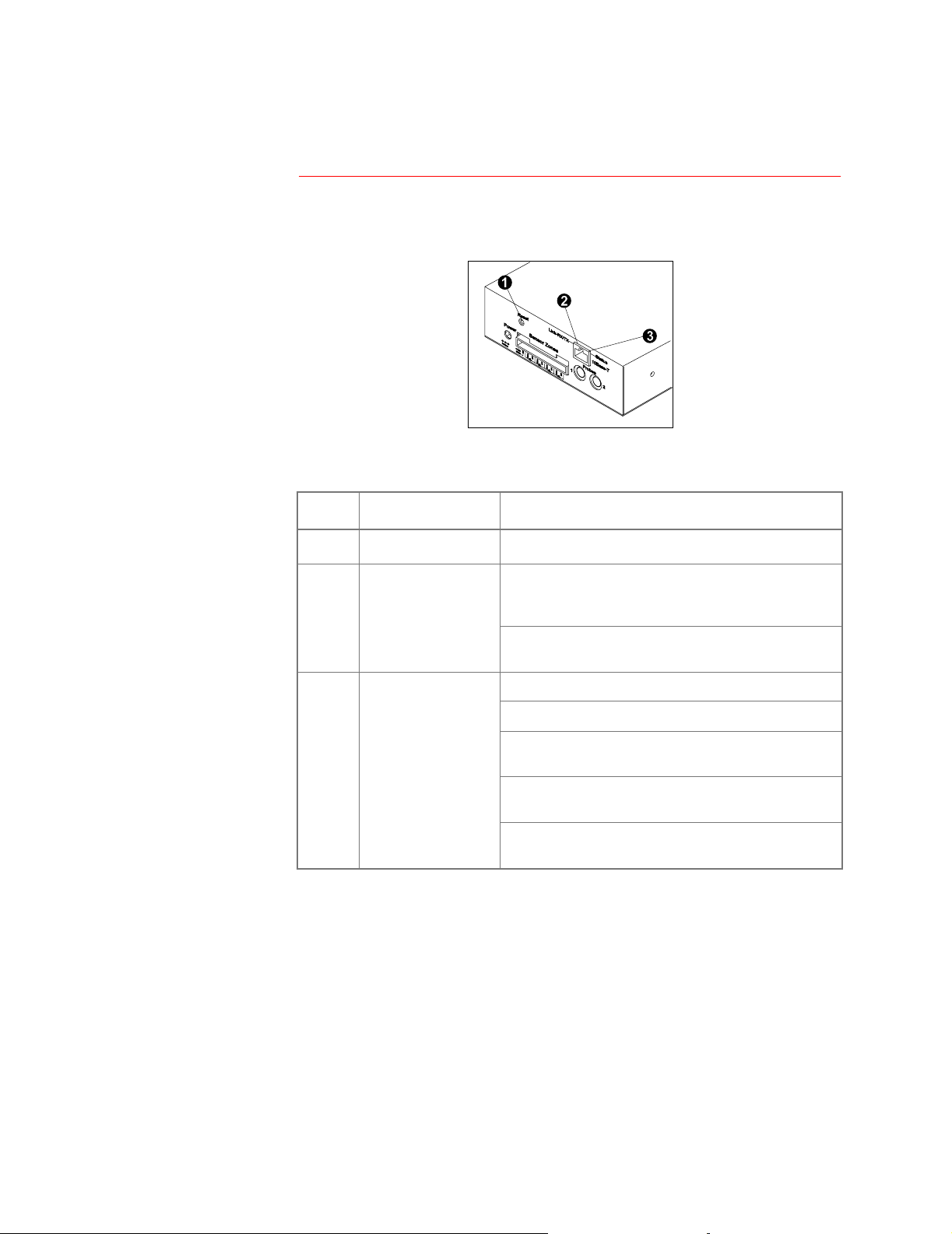
LEDs and the Reset Button
Front Panel Features
Descriptions
The reset button and two LEDs are on the front panel of the
Environmental Monitoring Unit.
No.
No. Feature
No.No.
!
"
Feature Description
FeatureFeature
Reset button Reinitializes the unit’s network interface.
RX/TX LED
Link-
Off: The devi ce that c onnects the
(a router, hub, or concentrator) is off or not
operating correctly.
Flashing green: The unit is receiving data packets
from the network.
Description
DescriptionDescription
unit
to the network
#
Status LED Off: The
Solid green: The
Flashing green: The
network settings.
Solid red: A hardware failure has been detected in
the
Blinking Red (Slowly): The
requests.
unit
has no power.
unit
.
unit
has valid network settings.
unit
does not have valid
unit
is making
BOOTP
Environmental Monitoring Unit: User’s Guide 2
Page 7

Managing the Unit
Web Interface
System requirements
Access to the Web interface
To access the Web interface, you need one of the following supported
Web browsers:
• Internet Explorer 3.0.2 and later
• Netscape 3.0 and later
APC
Note: Some Web interface features (dat a verif icati on,
Assistant, and
Script and/or Java. For
have cookies enabled on your Web browser.
Only one user at a time may access the Environmental Monitoring Unit.
Serial interface users have precedence over Telnet users and Telnet
users have precedence over Web users.
In the URL Location field of your W eb browser, type
by your unit’s IP address. For example:
http://170.241.17.51
Note: Alternatively, you can enter the DNS name (if a DNS server
entry is configured for the unit’s management card).
If the unit’s W eb port i s set to a val ue other than 80 , enter the System IP
address, a colon and the port value (in this example 8000).
MD5
authentication) requi re that you enable Ja va
MD5
to function properly, you must also
http://
Interactive
followed
Logging in
http://170.241.17.51:8000
After entering the Environmental Monitoring Unit’s IP address, press
NTER
. At the prompts, enter your user name and password (apc by
E
default for both).
Note: To change the user name, password, or time-out value, see
User Manager on page 16.
Environmental Monitoring Unit: User’s Guide 3
Page 8

Managing the Unit
Control Console
Options for using the Control Console
Access to the Control Console
The Control Console provides comprehensive management of th e unit
by one of the following modes of access:
• Telnet, for remote management
• A serial interface for local management
Only one user at a ti me may acces s the Envi ronmental Monitor ing Unitt .
Serial interface users have precedence over Telnet users, and Telnet
users have precedence over Web users.
Use a serial interface to access the Control Console:
1. Use the supplied configuration ca ble (APC part number 940-
0120) to connect the terminal port to one of the Probe Ports on
the Environmental Monitoring Unit.
2. Set the terminal port for the following communication settings:
Baud Rate 2400
Data Bits 8
Stop Bits 1
Parity None
Handshaking None
Logging in
Local Echo Off
Terminal Type
ANSI (VT100
)
3. To change the communications settings using HyperTerminal:
a. Make the needed changes.
b. Select
c. Select
d. Press E
Disconnect in the Call menu.
Connect in the Call menu.
NTER
4. Log into the Control Console. (See Logging in on this page.)
When prompted, enter the Administrator user name and password (
by default, for both).
To change the user name, password, or timeout value, see
Manager on page 16
.
User
Continued on next page
apc,
Environmental Monitoring Unit: User’s Guide 4
Page 9

Managing the Unit
Control Console
Navigating the menus
Within the menu structure:
continued
• To select a menu item, type the item number, then press E
• To save changes to configurable val ues, use the
Changes
• To refresh the current menu, Press E
• To go to the previous menu, Press E
• to access brief descriptions of the cur rent menu items, Type
and then press E
• To return to the main Control Console menu, use C
menu option.
NTER
NTER
.
SC
.
(if the menu has help available).
Accept
TRL
-C.
NTER
?
.
Environmental Monitoring Unit: User’s Guide 5
Page 10

Managing the Unit
Password-Protected User Accounts
Types of accounts
Account access to management menus
The Environmental Monitoring Unit provides two password-protected
accounts, Administrator and Device Manager, that allow you to control
access to the device. To conf igure the accounts, see
page 16
Account Type
Account Type
Account TypeAccount Type
Management Menus
Management Menus
Management MenusManagement Menus
Administrator
Administrator Device Manager
AdministratorAdministrator
Environmental Monitoring Yes Yes
Event Log Yes Yes
Network Yes No
System Yes No
Logout Yes Yes
Help Yes Yes
Link Yes Yes
User Manager on
Device Manager
Device ManagerDevice Manager
Environmental Monitoring Unit: User’s Guide 6
Page 11

Environmental Monitoring Unit
Menu Items
Introduction
Interface similarities and differences
Contents of this section
The information in this section is based on the Web interface. The
Control Console interface var ies slight ly, but offer s the same capabil ities
for managing the Environmental Monitoring Unit.
Your access to menus is determined by the account under which you
logged in. See
This section provides information on the following menus:
•
Environmental Monitoring on page 8
• Events on page 10
• Network on page 12
• System on page 16
• Help on page 20
Note: To manage the unit with SNMP, see page 23.
Password-Protected User Accounts on page 6.
Environmental Monitoring Unit: User’s Guide 7
Page 12

Menu Items
Environmental Monitoring
Purpose
Status: probes
Use the Environmental Monitoring menu to configure sett ings for
monitoring contact closures and for obtaining information about the
temperature and humidity sensed by up to two probes.
Item
Item Definition
ItemItem
Temperature Reports the temperature (C els iu s) sen sed by the u nit ’ s
probes.
High Temperature
Violation
Low Temperature Violation Reports whether current temperature violates the low
Humidity Reports the relative humid ity (as a percen tage) s ensed
High Humidity Violation Reports whether current humidity exceeds the high
Low Humidity Violation Reports whether current humidity violates the low
Reports whether current tem peratu re exce eds the high
temperature threshold (
threshold is disabled.
temperature threshold (
threshold is disabled.
by the unit’s probes.
humidity threshold (
threshold is disabled.
humidity threshold (
threshold is disabled.
Definition
DefinitionDefinition
or No) or reports that the
Yes
or No) or reports that the
Yes
or No) or reports that the
Yes
or No) or reports that the
Yes
Trap Thresholds Defines the thresholds for hig h and low temper ature (in
Celsius) and for rel ative humidity (as a perce ntage) that
the unit uses to identify a trap condition.
Send Traps On Enables or disables sending traps for each threshold.
Continued on next page
Environmental Monitoring Unit: User’s Guide 8
Page 13

Menu Items
Environmental Monitoring
Status: contacts
Item
Item Definition
ItemItem
Device 1 (Contact Zone 1)
Alarm through Device 4
(Contact Zone 4) Alarm:
Status: firmware version
Configuration
The status section also reports the firmware ver sion of the
Environmental Monitoring Unit.
Item (for each probe)
Item (for each probe) Definition
Item (for each probe)Item (for each probe)
Trap Threshold Options Defines the thresholds for high and low temperature (in
Contact Name 1–4 Defines a name of up to 16 characters for each contact.
continued
Definition
DefinitionDefinition
For each contact by number and name, reports
whether th e contact senses an alarm condition
(
or No) or that the alarm is disabled .
Yes
Definition
DefinitionDefinition
Celsius) and relativ e humidi ty (as a perc entage ) that th e
unit uses to identify a trap condition. (You must enable
the
Send Traps
item for the unit to react to the alarm.)
Contact Zone 1–4 Enables or disables the contacts.
Environmental Monitoring Unit: User’s Guide 9
Page 14

Menu Items
Events
Viewing the Event Log directly
Retrieving the Event Log using FTP
The Event Log displays information for the Environment al Monitoring
Unit’s last 300 events.
Item
Item Description
ItemItem
Date The date on which the event occurred (DD/MM/YYYY)
Time The time at which the event occurred (HH:MM:SS)
Event Description of the event. For detailed descriptions of event codes,
APC
select
interface and read the page about event codes.
Interactive Assistant from the Navigation Bar on the Web
To view the Event Log, select the
Web interface or press C
TRL
+ L in the Control Console.
Description
DescriptionDescription
Log option of the Events menu in the
To retrieve the Event Log using client side FTP:
1. From an MS-DOS prompt, type
ftp card-ip
, where
card-ip is the IP address of the Environmental Monitoring
Unit.
2. Log in to the unit's FTP server
3. type dir
4. To retrieve the Event Log, type
to list files.
get event.txt
. The
Environmental Monitoring Unit transmits the Event Log, which
includes at least the last 300 events, to your loca l drive. A
confirming message simiar to the following is displayed.
ftp: 3694 bytes received in 0.11 Seconds
33.58Kbytes/sec.
Viewing the event.txt file
You can use a spreadsheet program to v iew the event.txt file. The f ile is
TAB-delimited to appear in columns in the spreadsheet.
Note: To display the yea r in 4-digit format in the spreadsheet, be su re
to select that date format in the spreadsheet ap plication.
The event.txt file contains the following i nformation that is not displayed
in the Web and Control Console Event Log screens.
• The version of the event.txt file format (first field).
• The Date and Time the event.txt file was retrieved.
• The Name, Contact, Location, and IP address of the unit’s
management card.
• An unique Event Code for every type of event.
Continued on next page
Environmental Monitoring Unit: User’s Guide 10
Page 15

Menu Items
Events
Deleting the Event Log in the FTP interface
Recipients (Web interface only)
continued
To delete the Event Log, type
deletion:
Requested file action okay, completed.
A new event.txt file is immediately created to record the Deleted Log
event.
Use the
recipients who will be notified when an event occurs. See
Email Recipients on page 21
option on the
Recipients option of the Events menu to configure email
Network menu instead.)
del event.txt
. (In the Control Console, use the Email
. FTP confirms the
Configuring
Environmental Monitoring Unit: User’s Guide 11
Page 16

Menu Items
Network
Purpose
TCP/IP
TFTP/FTP
The
Network menu provides access to the configurable network
settings. Only the Administrator can access the
Network menu.
The TCP/IP section lists the Environmental Monitoring Unit’s start-up
settings for network service and allows you to configure TCP/IP
settings.
.
Item
Item Definition
ItemItem
System
Subnet Mask A 32-bit character string us ed t o se le ct s om e of the bits fro m an
Default Gateway A device that co nnects two comp uter netw orks that u se dif ferent
BOOTP
IP
The unit’s Internet Proto col address, whic h is a numeric addres s
that the domain name server translates into a domain name.
Internet address to route it to the subnet.
protocols so that the connected networks can exchange data.
Default: Router address
A protocol used to enable a diskless workstation to find its own
logical IP address at startup.
Settings: Enabled/Disabled
Definition
DefinitionDefinition
Use the TFTP/FTP section to control file transfers through the setti ngs
for the TFTP and FTP Client and FTP Server.
Client or Server
Client or Server Item
Client or ServerClient or Server
TF TP Clien t Remote Server IP: The network address of the
FTP Client Remote Server IP: The network address of the
User Name The user name for access to the
Password: The password for access to the
FTP Server Access: Enables or disables
Port: The
Item Definition
ItemItem
server used for downloads.
server used for downloads.
FTP
server.
FTP
server.
access.
server for the unit’s manage me nt
card is loca ted.
Default: port
Definition
DefinitionDefinition
TCP/IP
port on which the
21
FTP
server
Continued on next page
TFTP
FTP
FTP
Environmental Monitoring Unit: User’s Guide 12
Page 17

Menu Items
Network
Telnet/Web
continued
Access Enables or disables Telnet access.
Port The
Access Enables or disables Web access.
Port The
Item
Item Definition
ItemItem
TCP/IP
port where the Telnet server for the unit is located.
Default: port
TCP/IP
Default: port
23
port where the Web server for the unit is located.
80
Te l n e t
Te l n e t
Te l n e tTe l n e t
Web
Web
WebWeb
Definition
DefinitionDefinition
Continued on next page
Environmental Monitoring Unit: User’s Guide 13
Page 18

Menu Items
Network
SNMP
continued
The SNMP section displays the SNMP access control and trap receiver
Settings.
SNMP Access Enables or disables
Access Control Controls access to each of the four
Trap Receiver Defines the
Access Control .
current settings for all four SNMP channels and lets you confi gure
values for a selected channel.
Community
Name
Item
Item Definition
ItemItem
NMSs
Definition
DefinitionDefinition
SNMP
access.
(up to 4) to which traps are sent.
The Access Control section of SNMP displays the
Item
Item Definition
ItemItem
Password that the
SNMP
for
the allowed access.
Note: Allows a maximum of 15 characters.
access to the unit. The
NMS
Definition
DefinitionDefinition
specified by the
Access Type
SNMP
NMS IP
channels.
option must us e
option defines
NMS
NMS IP Configures the channel to allow only one
NMS IP
address), or all
value), to have access to the channel.
Access Type Defines whether the
GET
GET
s and
Trap Receiver.
write (use
(cannot use
The Trap Receiver section of SNMP displays and lets
s or
NMS
s (using
NMS
identified by the
SET
s) or read (use only
SET
s ).
0.0.0.0
(using a specific
NMS IP
for the
NMS IP
option can
GET
s) or is disabled
you configure the current settings for all four trap receivers.
Item
Item Definition
ItemItem
Community Name The password that the unit uses when it sends traps to the
NMS identified by the
Maximum length: 15 characters.
Receiver
Trap Generation Enables or disables the sending of traps to the
Authentication Traps Enables or disables the sending of authentication traps to
NMS IP
The specific
sent by the unit.
Note: To send no traps to any
identified by the
NMS
the
NMS
IP
0.0.0.0
to
Receiver NMS IP
identified by the
Definition
DefinitionDefinition
Receiver NMS IP
(defined by its IP address) to receive traps
NMS
Receiver NMS IP
option.
, set the Trap Receiver
NMS
option.
.
option
Continued on next page
Environmental Monitoring Unit: User’s Guide 14
Page 19

Menu Items
Network
Email (Control Console only)
continued
Use the
who will be notified when an event occurs. See
Recipients on page 21
of the
Email option of the Network menu to configure email recipients
Configuring Email
. (In the Web interface, use the Recipients option
Events menu instead.)
Environmental Monitoring Unit: User’s Guide 15
Page 20

Menu Items
System
Purpose
User Manager
Use the
transfers, and links. Only the Administrator has access to the
System menu to configure accounts, system identification, file
System
menu.
Use this section to configure the propert ies of the Administrator and
Device Manager accounts. The Administrator has unrestricted access,
but the Device Manager can configure only the Environmental
Monitoring Unit; not the network and system parameters.
Item
Item Definition
ItemItem
Auto Logout How long you can be ina ctive before t he sy stem a utoma ticall y log s
you out.
Default: 3 minutes.
Authentication
Administrator
User Name User name (
(the default) causes the W eb Interface to use standard
Basic
1.1
login (base64 encoded passwords)
causes the Web Interface to use an MD5-bas ed
MD5
authentication login. (For
cookies enabled on your browser.)
10
characters maximum).
Default:
apc
Definition
DefinitionDefinition
MD5
to function properly, you must have
HTTP
Password Password only for
maximum).
Default:
Authentication
Phrase
User Name User name (10 characters maximum).
Password Password only for
Authentication
Phrase
Authentication phrase (only for
to
Default:
Default:
maximum).
Default:
Authentication phrase for
characters.
Default:
apc
32
characters.
admin user phrase
apc
apc
device user phrase
HTTP 1.1
Device Manager User
Device Manager User
Device Manager UserDevice Manager User
HTTP 1.1
authentication (10 characters
MD5
authentication (10 characters
MD5
. The phrase must be from
). The phrase must be from 15
32
15 to
Continued on next page
Environmental Monitoring Unit: User’s Guide 16
Page 21

Menu Items
System
continued
Identification
Date/Time
Use this section to display and c onfigure the unit’s system identification
values. The following items are configurable:
Item
Item Definition
ItemItem
Name The unit’s system name (used as the
Contact The unit’s contact or owner (used as the
Location The unit’s physical location (used as the
Item
Item Definition
ItemItem
Date The date for the system in the form of MM/DD/YYYY.
Time The time for the system in the form of HH:MM:SS (24 hour time).
Definition
DefinitionDefinition
SNMP MIB-II
Definition
DefinitionDefinition
sysName
SNMP MIB-II
SNMP MIB-II
OID
sysContact
sysLocation
).
OID
.
OID
Continued on next page
Environmental Monitoring Unit: User’s Guide 17
Page 22

Menu Items
System
File Transfer
continued
Remote
Remote
Remote
Remote
Item
Item Description
ItemItem
Display the current transfer settings
Display the current transfer settings
Display the current transfer settingsDisplay the current transfer settings
TFTP
Server
FTP
Server
FTP
ServerUser Name User name of the
FTP
Server Password Password of the
IP
IP IP
IP address of the remote
the
Network
TFTP: Remote Server
address of the remote
the
Network
FTP: Remote Server
Network
FTP Client: User Name
Network
FTP Client: Password
menu’s
menu’s
menu’s
menu’s
TFTP/FTP
FTP
TFTP/FTP
Description
DescriptionDescription
TFTP
server defined in
TFTP/FTP
IP
TFTP/FTP
IP
FTP
server defined in the
server defined in the
settings.
FTP
server defined in
settings.
settings.
settings.
Configure the Name of the File to Download
Configure the Name of the File to Download
Configure the Name of the File to DownloadConfigure the Name of the File to Download
Filename The name of the file to be downloaded
Initiate the Transfer
Initiate the Transfer
Initiate the TransferInitiate the Transfer
Result of Last File Transfer Display the results of the last file transfer.
Initiate File Transfer Via Choose to transfer the file by
TFTP
or
FTP
.
Environmental Monitoring Unit: User’s Guide 18
Page 23

Menu Items
System
continued
Tools
Links (Web Interface only)
Item
Item Description
ItemItem
No Action Causes no action.
Reboot Card Re-initializes the unit’s management card.
Reset Card to Defaults Restores all configuration settings to their
defaults, including user accounts, and
enables
Reset Card to Defaults Except
TCP/IP
Restores all configuration settings (except
TCP/IP
) to their defaults.
BOOTP
Description
DescriptionDescription
.
Use this section to configure URL links that appear on the Navigat ion
menu at the left. (The APC Links are pre-defined, but can be changed.)
Item
Item Definition
ItemItem
Configure the User Links
Configure the User Links
Configure the User LinksConfigure the User Links
Definition
DefinitionDefinition
Name For each link, the name that will appear on the menu bar.
URL The
Name View the names of the
URL Define the
HTTP
Configure the APC Links
Configure the APC Links
Configure the APC LinksConfigure the APC Links
link in
URL
of each
URL
form:
http://mysite.com/mypage.com
APC
links.
APC
link.
.
Environmental Monitoring Unit: User’s Guide 19
Page 24

Menu Items
Help
Help options
Interactive Assistant
About Card
In the Web interface:
• The
• The Contents page provides an overview of parameters that
• To access help about a page, click the ? at the end of th e black
In the Control Console, type
Interactive Assistant brings APC Customer Serv ice to the Web. When
you select Interactive Assistant, the Environmental Monitoring Unit
transmits information about the Environmental Monitoring Unit’s
management card to APC’s Interactive Assistant server. The server
informs you if a newer version of firmware is available and can link you
to extensive context-sensitive help.
About Card displays information about the Environmental Monitoring
Unit’s hardware, applicati on module, and APC OS, including the serial
number , hardware revision, and the date and time at which the AOS
was loaded.
Help menu is at the lower left.
you can display and configure.
title bar of that page.
for help about the current menu.
?
Environmental Monitoring Unit: User’s Guide 20
Page 25

Environmental Monitoring Unit
Configuring and Using Email Notification
Configuring Email Recipients
Menu options
Settings
To identify up to four email recipients, use one of the following:
• The
• The
Setting
Setting Description
SettingSetting
To Address
Send via
Recipients
Email
Defines the user and domain names of the recipient.
To use email for paging, use the email address for the recipient’s
pager gateway account (for example,
pager gateway generates the page.
Note:
Lets you choose one of the following methods for routing email:
• Send email through the Environmental Monitoring Unit’s SMTP
server. Selecting
option, ensures that the email is sent before the unit’s 20-second
timeout, and, if necessary, is retried several times.
• Send email directly to the recipient’s remote SMTP server. If you
select the
server is busy, the timeout ma y prevent some ema il from being sent,
With this option, the management card tries to send the email only
once.
When the recipient uses the Environmental Monitoring Unit’s SMTP
server, this setting has no effect.
option of the Web interface’s
option of the Control Console’s
Description
DescriptionDescription
The recipient’s pager must be able to use text-based
messaging.
Local SMTP Server
Recipient’s SMTP Server
myacct100@skytel.com
, which is the recommended
option, and the remote SMTP
Events
Network
menu
Menu
). The
Configuring the local SNMP server
Email
Generation
When you select the
you must do one of the following:
Enables (by default) or disables sending email to the defined
recipient.
Local SNMP Server
option for the
Send via
setting,
• Make sure that forwarding is enabled at that server so that the
server can route email to external SMTP servers.
Note:
Always see your SMTP-server administrator before
changing the configuration of your SMTP server.
• Set up a special email account for the Environmental Monitoring
Unit. This account then forwards the Email to an external email
account.
Testi n g Em a il
n the Web interface, use the
I
Email Test
option to send a test email
message to a configured recipient.
Environmental Monitoring Unit: User’s Guide 21
Page 26

Configuring and Using Email Notification
Configuring SMTP and DNS Settings
Requirements for
using SMTP
DNS server
To use the Simpl e Mail T ransfer Pr otocol (SMTP) t o send email whe n an
event occurs, you must define the following settings:
• The IP address of the Domain Name Service (DNS) server.
• The DNS name of the
settings for
SMTP.
SMTP
server and the
From Address
• The email addresses for a maximum of four recipients.
Note:
To page an email recipient who uses a text-based pager
gateway, see the description of the
in
Settings on page 21.
To Address
setting
To enable the Environmental Monitoring Unit to send email messages,
you must use the
TCP/IP & DNS
(Control Console) in the
Network
option (Web interface) or
menu to identify the Domain Name
DNS
option
Service (DNS) server by its IP address.
If the unit does not receive a response from the DNS server within five
seconds, email cannot be sent. Therefore, use a DNS server on the
same segment as the unit or on a nearby segment (but not across a
WAN).
After you define the DNS serve r’s IP address, verify that DNS is working
correctly by entering the DNS name of a computer on your network to
obtain the IP address for that DNS name.
SMTP settings
The
Email
option in the
Network
menu accesses the following SMTP
settings:
Setting
Setting Description
SettingSetting
SMTP Server
From Address
The DNS name of the SMTP server.
The contents of the
the Environmental Monitoring Unit.
Note:
See the documentation for your SMTP server to
determine whether you must you use a valid user
account on the server for this setting.
Description
DescriptionDescription
field in the email messages sent by
From
Environmental Monitoring Unit: User’s Guide 22
Page 27

Environmental Monitoring Unit
Managing the Unit with SNMP
SNMP Interface
Purpose
PowerNet MIB OID
categories
You can use PowerNet
control) your Environmental Monitoring Unit.
Use your MIB browser to locate the PowerNet
use to manage the Environmental Monitoring Unit:
1. Select
2. Select
3. Select
OID
OID Function
OIDOID
[mUpsEnviron]
[mUpsContact]
[product] under [apc].
[hardware].
[measureUps] to list the following two
MIB OID
Displays information about the ambient temperature and
relative humidity.
Defines contact values .
s to manage (monitor, configure, and
Function
FunctionFunction
MIB OID
OID
s that you can
categories:
Environmental Monitoring Unit: User’s Guide 23
Page 28

Managing the Unit with SNMP
Using the OIDs
Using monitoring OIDs
Using contact OIDs
Use the read-only
[mUpsEnviron]
humidity values.
OID
OID Function
OIDOID
mUpsRelativeHumidity
mUpsAmbientTmperature
Use the
[mUpsContact]
sensor values.
OID
OID Function
OIDOID
mUpsContactNumContacts
{mUpsContactTable}
OID
s to view temperature and
Function
FunctionFunction
Reports the relative humidity sensed by the probes.
Reports the ambient temperature in Celsius, sensed
by the probes.
OID
s to view and configure the current contact
Function
FunctionFunction
Lists how many contact sensors the unit uses.
Lists the OIDs for each contact sensor:
contactNumber
which the other OIDs apply.
normalState
condition (unknown, open , or closed).
description
sensor
monitoringStatus
sensor is bei ng monitored
currentStatus
condition (unknown, noFault, or fault).
: Identifies the contact sensor for
: Defines the contact sensor’s normal
: Defines the purpose of the contact
: Defines whether the contact
: Identifies the sensor’s current
Environmental Monitoring Unit: User’s Guide 24
Page 29

Environmental Monitoring
Security
Security Features
Planning and implementing security features
Port assignments
User names, passwords, community names
As a network device that passes information across the network, the
Environmental Monitoring Unit is subject to the same exposure as
other devices on the network.
Use the information in this section to plan and implement the security
features appropriate for your environment.
FT P
If a Telnet,
specify the port when using the client interface, such as a Web
browser. The non-standard port address becomes an extra
“password,” hiding the server to provide an additional level of security.
TCP
The
initially set at the standard “well known ports” for the protocols.To hide
the interfaces, use any port numbers from
For an example of how to access a client interface for which the por t is
non-standard, see
All user names, passwords, and community names for
transferred over the network as plain te xt. A user who is capable of
monitoring the network traffic can determine the user names and
passwords required to log into the Environmental Monitoring Unit’s
Control Console or Web interface as an Administr a tor or Device
Manager . This security limitation of the protocols aff ects any device
using Telnet, a Web server, or an
, or Web server uses a non-standard port , a user must
ports for which the Telnet,
Access to the Web interface on page 3.
FTP
, and Web servers listen are
5000 to 65535
SNMP
version 1 agent.
.
SNMP
are
Environmental Monitoring Unit: User’s Guide 25
Page 30

Security
Authentication
Authentication versus encryption
MD5 authentication (Web interface)
The Environmental Monitoring Unit contr o ls access by providing basic
authentication through user names, passwords, and
provides no type of encryption. These basic securi ty features are
sufficient for most environments, in which sensitive data is not being
transferred. To ensure that data and communication between the
Environmental Monitoring Unit and the client interfaces, such as Telnet
and the Web browser, cannot be captured, you can provide a greater
level of security by enabling
See
MD5 authentication (Web interface) on this page.
The Web interface option for
of access security than the basic
MD5
scheme is similar to
Enabling
MD5
implements the following security features:
• The Web server requests a user name and a password phrase
(distinct from the password). The user name and password
phrase are not transmitted over the network, as they are in
basic authentication. Instead, a Java login applet combines the
user name, password phrase, and a unique session challenge
number to calculate an
number is returned to the server to verify that the user has the
correct login information;
the login information.
• In addition to the login authentication, each form post for
configuration or control operati ons is authenticated with a
unique challenge and hash response.
• After the authentication login, subsequent page access is
restricted by
must have cookies enabled in your browser.) Pages are
transmitted in their plain-text form, with no encryption.
IP
MD5
authentication for the Web interface.
MD5
authentication enables a higher level
HTTP
authentication scheme. The
CHAP
addresses and a hidden session cookie. (You
PAP
and
MD5
MD5
remote access protocols.
hash number. Only the hash
authentication does not reveal
IP
addresses, but
MD5
authentication, which is availab le onl y for the Web
SNMP
, you can disable write-only access so that read
RFC
document #
MD5
authentication provides a much higher le vel of security
1321
CHAP
at the Web site of the
RFC
, see
document #
FTP
, and
1994
Firewalls
If you use
interface, disable the less secure interfaces, including Telnet,
SNMP
. For
access and trap facilities are st ill available. For additional in formation on
MD5
authentication, see
Internet Engineering Task Force. For
Although
than the plain-text access methods, complet e protection from security
breaches is almost impossible to achieve. Well-configured firewalls are
an essential element in an overall security scheme.
Continued on next page
Environmental Monitoring Unit: User’s Guide 26
.
Page 31

Security
Authentication
Summary of access methods
continued
The following table describes interfaces and its access methods.
Interface
Interface Security Access
InterfaceInterface
Serial Control
Console
Te lnet Control
Console
SNMP
Access is by user name and
password.
These methods are available:
These methods are available:
Security Access Notes
Security AccessSecurity Access
Always enabled.
The user name and password
• User name and password
• Selectable server port
• Server Enable/Disable
• Community Name
NMS IP
•
• Agent Enable/Disable
• Four access communities with
filters
read/write/disable capability
are transmitted as plain text.
The NMS IP filters allow access
from designated IP addresses.
• 159.215.12.1 allows only the
NMS with that IP address to
have access.
• 159.215.12.255 allows
access for any NMS on the
159.215.12 segment.
• 159.215.255.255 allows
access for any NMS on the
159.215 segment.
• 159.255.255.255 allows
access for any NMS on the
159 segment.
• 0.0.0.0 or 255.255.255.255
allows access for any NMS.
Notes
NotesNotes
FTP Server
Web Se rver
These methods are available:
• User name and password
• Selectable server port
• Server Enable/Disable
These methods are available:
• User name and password
• Selectable server port
• Server Enable/Disable
MD5
Authentication option
•
Only the Administrator account
has access.
In basic
mode, the user name and
password are transm itte d b as e64 encoded (with no
encryption).
mode uses a user name and
password phrase.
HTTP
authentication
MD5
authentication
Environmental Monitoring Unit: User’s Guide 27
Page 32

APC Worldwide Customer Support
Customer support for this or any other
APC
Customer Support in any of the following ways:
• Use an
documents in the
–
APC
web page to find answers to frequently asked questions (
APC
http://www.apcc.com
Connect by links to
Knowledge Base, and to submit customer support requests.
(Corporate Headquarters)
APC
APC
web pages for specific countries and regions, each of which
provides customer support information.
http://www.apcc.com/support
–
/
Submit customer support requests.
APC
• Contact local or regional
Customer Support by telephone or e-mail.
– For e-mail addresses and local, country-spec ific, customer support telephone
numbers worldwide, go to
http://www.apcc.com/support/contact
– For e-mail addresses and technical suppo rt telephone numbers of major
customer support centers, use the following list:
APC
Headquarters
Headquarters
Headquarters Headquarters
U.S
((((
. and Canada)
. and Canada)
. and Canada). and Canada)
Latin America
Latin America
Latin AmericaLatin America
Europe, Middle East,
Europe, Middle East,
Europe, Middle East, Europe, Middle East,
Africa
Africa
Africa Africa
product is available at no charge. You can contact
FAQ
s), to access
.
APC
regional
(1) (800) 800-4272 (toll free)
(1) (401) 789-5735 (United
States)
apctchla@apcc.com
(353) (91) 702020 (Ireland)
apceurtech@apcc.com
(03) 5434-2021
jsupport@apcc.com
APC
• Contact the
hardware device or
Japan
Japan
JapanJapan
APC
representative or ot her distributor from whom you purchased your
APC
software application for information on how to obtain local
customer support.
Entire contents copyright © 2001 American Power Conversion. All rights reserved. Reproduction
in whole or in part without permission is prohibited. APC and the APC logo are registered
trademarks of American Power Conversion Corporation. All other trademarks,
product names, and corporate names are the property of their respective
owners and are used for informational purposes only.
990-0815B 01/2001
 Loading...