

Page 1

Ethernet Switches
AP9224110
AP9224111
AP9224112
Installation, Troubleshooting,
Specifications
Page 2

This manual is available in English on the enclosed CD.
Ce manuel est disponible en français sur le CD-ROM ci-inclus.
Dieses Handbuch ist in Deutsch auf der beiliegenden CD-ROM verfügbar.
Questo manuale è disponibile in italiano nel CD-ROM allegato.
O manual em Português está disponível no CD-ROM em anexo.
Este manual está disponible en español en el CD-ROM adjunto.
Page 3

Contents
Introduction.............................................................1
Product Features and Package Contents . . . . . . . . . . . . . . . . . . 1
Overview . . . . . . . . . . . . . . . . . . . . . . . . . . . . . . . . . . . . . 1
Features . . . . . . . . . . . . . . . . . . . . . . . . . . . . . . . . . . . . . . 1
Package Contents . . . . . . . . . . . . . . . . . . . . . . . . . . . . . . . 2
Installation . . . . . . . . . . . . . . . . . . . . . . . . . . . . . . . . . . . . . . . . 3
Desktop installation . . . . . . . . . . . . . . . . . . . . . . . . . . . . . . 3
Rack-mounted installation . . . . . . . . . . . . . . . . . . . . . . . . . . 3
Power On . . . . . . . . . . . . . . . . . . . . . . . . . . . . . . . . . . . . 4
Connecting the switch . . . . . . . . . . . . . . . . . . . . . . . . . . . . 4
Installing a mini-GBIC (SFP) transceiver . . . . . . . . . . . . . . . . . 5
Removing a mini-GBIC (SFP) transceiver . . . . . . . . . . . . . . . . 5
Hardware.................................................................6
24-Port 10/100 Switch . . . . . . . . . . . . . . . . . . . . . . . . . . . . . . . 6
Front Panel . . . . . . . . . . . . . . . . . . . . . . . . . . . . . . . . . . . 6
Rear Panel . . . . . . . . . . . . . . . . . . . . . . . . . . . . . . . . . . . . 7
24-Port 10/100 Switch with 2 Gigabit Uplink. . . . . . . . . . . . . . . 8
Front Panel . . . . . . . . . . . . . . . . . . . . . . . . . . . . . . . . . . . 8
Rear Panel . . . . . . . . . . . . . . . . . . . . . . . . . . . . . . . . . . . 10
24-Port 10/100/1000 Switch with 2 Gigabit Uplink . . . . . . . . . 11
Front Panel . . . . . . . . . . . . . . . . . . . . . . . . . . . . . . . . . . 11
Rear Panel . . . . . . . . . . . . . . . . . . . . . . . . . . . . . . . . . . . 13
Troubleshooting.....................................................14
How to Resolve Problems . . . . . . . . . . . . . . . . . . . . . . . . . . . . 14
APC Ethernet Switches: Installation, Troubleshooting, Specifications i
Page 4

Specific Problems and Their Solutions. . . . . . . . . . . . . . . . . . . . 15
Diagnosing LED Indicator . . . . . . . . . . . . . . . . . . . . . . . . . 15
Power . . . . . . . . . . . . . . . . . . . . . . . . . . . . . . . . . . . . . . 15
Incorrect connections . . . . . . . . . . . . . . . . . . . . . . . . . . . 15
Transmission Mode . . . . . . . . . . . . . . . . . . . . . . . . . . . . . 16
Technical Specifications ......................................... 17
24-Port 10/100 Switch (AP9224110) . . . . . . . . . . . . . . . . . . . . . . . 17
24-Port 10/100 Switch with 2 Gigabit Uplink (AP9224111) . . . . . . 19
24-Port 10/100/1000 Switch with 2 Gigabit Uplink (AP9224112) . 21
ii APC Ethernet Switches: Installation, Troubleshooting, Specifications
Page 5

Introduction
Product Features and Package Contents
Overview
The APC Ethernet Switch product line provides multi-port switches that can be used to create highspeed backbone connections among switches, servers, databases, and end stations. The switches fit
into any enterprise-level network as an exit to the backbone switch.
This document describes the following:
• 24-Port 10/100 Switch (AP9224110)
• 24-Port 10/100 Switch with 2 Gigabit Uplink (AP9224111)
• 24-Port 10/100/1000 Switch with 2 Gigabit Uplink (AP9224112)
Features
Each switch features;
• Automatic MDI/MDIX for all ports
• N-way Auto-negotiation
• Store-and-Forward architecture
• 1U 19-inch rack-mount design
• Internal power supply
• Integrated ventilation fan (AP9224112 only)
APC Ethernet Switches: Installation, Troubleshooting, Specifications 1
Page 6

Introduction: Product Features and Package Contents
Package contents
• One APC Ethernet Switch
• Power cord
• Four rubber feet
• Rack mount kit
• User’s Guide
Compare the contents of your Ethernet switch package with the checklist above. If any item is
missing or damaged, contact “APC Worldwide Customer Support” using the phone numbers on the
back cover of this guide.
2 APC Ethernet Switches: Installation, Troubleshooting, Specifications
Page 7
Installation
Desktop installation
Place the switch on a large, clean, level surface with a power outlet nearby. Make sure there is enough
clearance around the switch for attaching cables and the power cord, and for air circulation.
Attaching rubber feet.
1. Make sure the mounting surface on the bottom of the switch is free of grease and dust.
2. Remove the adhesive backing from the rubber feet.
3. Apply one rubber foot to each corner on the bottom of the switch to protect the switch from
shocks and vibrations.
Rack-mounted installation
The switch comes with a rack-mount kit and can be mounted in an EIA standard size, 19-inch rack.
The switch can be placed in a wiring closet with other equipment.
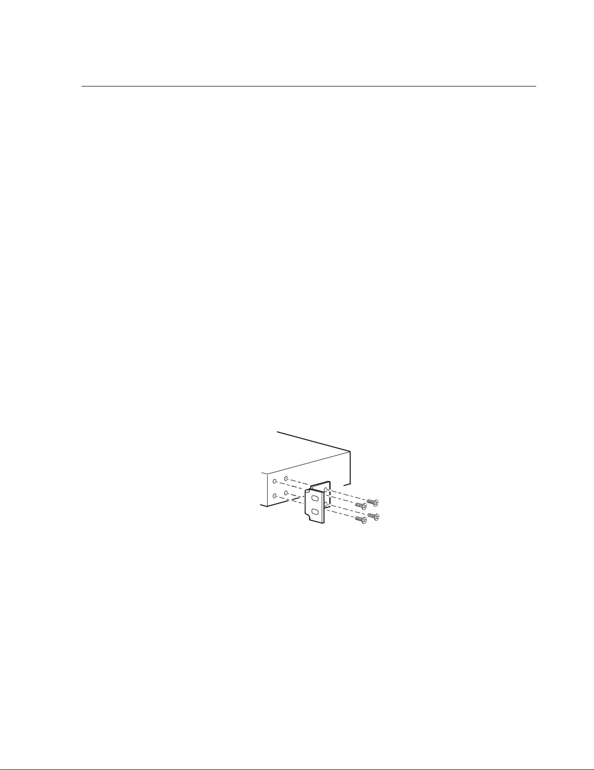
To mount the switch in a rack:
1. Position one bracket to align with the holes on one side of the switch and secure it with the
smaller bracket screws. Attach the remaining bracket to the other side of the switch.
APC Ethernet Switches: Installation, Troubleshooting, Specifications 3
Page 8
Introduction: Installation
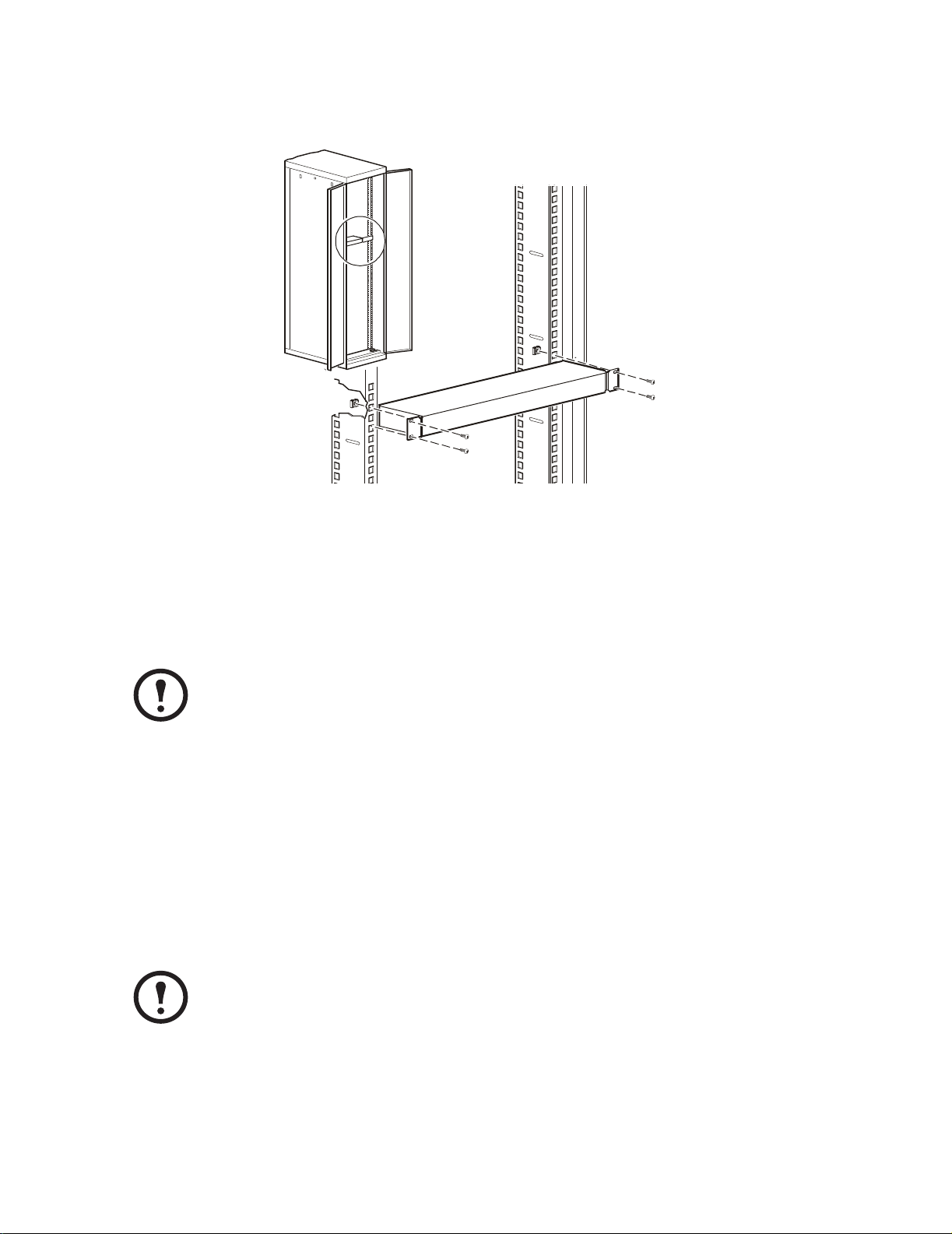
2. Position the switch in the rack by aligning the holes in the brackets with the appropriate holes
on the rack. Secure the switch to the rack with the rack-mounting screws.
Applying power
Connect the cord of the power adapter to the power socket on the rear panel of the switch. Connect
the other end of the power cord to an APC UPS that is connected to a power outlet. Check the power
indicator on the front panel to make sure that the switch is receiving power.
After you connect the power cord of an AP9224112, use the power switch on the rear
panel to supply power to the unit.
Note
Connecting the switch
The RJ-45 ports use either unshielded twisted-pair (UTP) or shielded twisted-pair (STP) cable.
• For 10 Mbps connections use 100Ω Category 3, 4, or 5 cable
• For 100 Mbps connections use 100Ω Category 5 cable
• For 1000 Mbps connections use 4-pair Category 5 copper cabling
The length of any twisted-pair connection must not exceed 328 feet (100 meters).
Note
4 APC Ethernet Switches: Installation, Troubleshooting, Specifications
Page 9

Installing a mini-GBIC (SFP) transceiver
To install a mini-GBIC (SFP) transceiver:
1. Insert the transceiver into the mini-GBIC port with the exposed section of PCB board facing
down.
2. Push the transceiver firmly until it clicks into place.
3. The switch automatically detects the installed transceiver. Check the LEDs to verify that it is
functioning properly.
Removing a mini-GBIC (SFP) transceiver
To remove a mini-GBIC (SFP) transceiver from the mini-GBIC port:
1. Remove the fiber-optic cables from the transceiver.
2. Unlock the transceiver’s latch (latch styles vary).
Introduction: Installation
3. Pull the transceiver out of the mini-GBIC port.
4. Put the dust cover on the transceiver.
APC Ethernet Switches: Installation, Troubleshooting, Specifications 5
Page 10

Hardware
24-Port 10/100 Switch
Front panel of the AP9224110 switch
LED indicators (two for each RJ-45 port)
24 10/100Base-TX RJ-45 ports
One Power LED indicator
LED Indicators. The LED indicators provide real-time information on the system’s operating status.
LED Status Description
Power Green Power is on.
Off Power is not connected.
LNK/ACT Green The port is connecting with the device.
Blinking The port is receiving or transmitting data.
Off No device is attached.
FDX/COL Orange The port is operating in full-duplex mode.
Blinking Packet collision occurred on this port.
Off No device is attached or the port is operating in half-
duplex mode.
6 APC Ethernet Switches: Installation, Troubleshooting, Specifications
Page 11

Rear Panel
A
The power input connector is located on the rear panel of the switch.
C INPUT 5 0/60 Hz
100-240V, 0.8A MAX
Hardware: 24-Port 10/100 Switch
APC Ethernet Switches: Installation, Troubleshooting, Specifications 7
Page 12

24-Port 10/100 Switch with 2 Gigabit Uplink
Front panel of the AP9224111 switch
LED indicators for each RJ-45 port
24 10/100Base-TX RJ-45 ports
Two auto-detect gigabit ports
Two mini-GBIC (Small Form Factor Plug-in) ports
One Power LED indicator
Mini-GBIC (SFP) ports. Mini-GBIC (SFP) transceivers use the separate mini-GBIC (SFP) ports.
Note
When you install the mini-GBIC (SFP) transceiver into the port on the switch, you must
disconnect any device connected to its partner gigabit copper port of the same number. If
the gigabit copper port is occupied, the switch will not detect the mini-GBIC (SFP) that
you installed.
8 APC Ethernet Switches: Installation, Troubleshooting, Specifications
Page 13

Hardware: 24-Port 10/100 Switch with 2 Gigabit Uplink
LED Indicators . Two LED indicators for each RJ-45 port and a power LED for each unit provide
real-time information on the system’s operating status.
LED Status Description
Power Green Power is on.
Off Power is not connected.
LNK/ACT Green The port is connecting with the device.
Blinking The port is receiving or transmitting data.
Off No device is attached.
FDX/COL Orange The port is operating in full-duplex mode.
Blinking Packet collision occurred on this port.
Off The port is operating in half-duplex mode.
Gigabit port LEDs. Each Gigabit port has the following LEDs.
LED Status Description
1000 (Gigabit port) Green The port is operating at 1000mbps
100 (Gigabit port) Orange The port is operating at 100mbps
LNK/ACT (Gigabit
port)
FDX/COL (Gigabit
port)
Green The port is connecting with the device.
Blinking The port is receiving or transmitting data.
Off No device is attached.
Orange The port is operating in full-duplex mode.
Blinking Packet collision occurred on this port.
Off The port is operating in half-duplex mode.
APC Ethernet Switches: Installation, Troubleshooting, Specifications 9
Page 14

Hardware: 24-Port 10/100 Switch with 2 Gigabit Uplink
Rear panel
The power input connector is located on the rear panel of the switch.
AC INPUT 50/60 HZ
100-24 0V, 0.8A MAX
10 APC Ethernet Switches: Installation, Troubleshooting, Specifications
Page 15

24-Port 10/100/1000 Switch with 2 Gigabit Uplink
Front panel of the AP9224112 switch
LED indicators (three for each RJ-45 port)
24 10/100/1000mbps Ethernet RJ-45 ports
Two Mini-GBIC (SFP) ports
One Power LED indicator
Mini-GBIC (SFP) ports. Mini-GBIC (SFP) transceivers use the separate ports 23 and 24. The switch
auto-detects between Gigabit copper and mini-GBIC (Giga fiber) connections.
When a mini-GBIC (SFP) transceiver is installed, the mini-GBIC (SFP) ports have
higher priority than the Giga copper ports 23 and 24.
Note
When mini-GBIC (SFP) transceivers are not installed, ports 23 and 24 are Gigabit copper only.
See “Mini GBIC (SFP) LEDs” on page 13
APC Ethernet Switches: Installation, Troubleshooting, Specifications 11
Page 16

Hardware: 24-Port 10/100/1000 Switch with 2 Gigabit Uplink
LED Indicators . The LED indicators provide real-time information on the system’s operating
status. There are three LED indicators for each RJ-45 port and a power LED for each unit.
LED Status Description
Power Green Power is on.
Off Power is not connected.
1000 Green The port is operating at 1000mbps.
Off No device is attached or the device is operating in 10/100mbps
mode.
LNK/ACT Green The port is connecting with the device.
Blinking The port is receiving or transmitting data.
Off No device is attached.
FDX/COL Orange The port is operating in full-duplex mode.
Blinking Packet collision occurred on this port.
Off No device is attached or the port is operating in half-duplex mode.
12 APC Ethernet Switches: Installation, Troubleshooting, Specifications
Page 17

Hardware: 24-Port 10/100/1000 Switch with 2 Gigabit Uplink
Mini GBIC (SFP) LEDs. Each mini-GBIC (SFP) port has one LNK and one ACT LED indicator.
LED Status Description
LNK Green The port is connecting with the device.
Off No device is attached.
ACT Green (Blinking) The port is transmitting or receiving data.
Off No data is being transmitted or received.
Rear Panel
The power input connector, on/off switch, and ventilation fan are located on the rear panel of the
switch.
AC INPUT 50/60 Hz
100-24 0V, 0.8A MAX
OFF / ON
APC Ethernet Switches: Installation, Troubleshooting, Specifications 13
Page 18

Troubleshooting
How to Resolve Problems
This chapter describes common problems that may occur when using the switch and their possible
solutions.
First, use the information in this chapter to attempt to resolve a problem. If you cannot resolve the
problem, contact APC Worldwide Customer Support using the numbers listed on the back cover of
this guide.
14 APC Ethernet Switches: Installation, Troubleshooting, Specifications
Page 19

Specific Problems and Their Solutions
Diagnosing LED Indicator
If the LNK LED does not illuminate after connection, check the following:
• Verify that the switch and any devices attached to it are turned on.
• Be sure the connecting cable is plugged into both the switch and its corresponding device.
• Verify that the proper cable type is used and its length does not exceed specified limits.
See “Connecting the switch” on page 4
Power
If the power indicator on the front panel of the switch does not turn on when the power cord is
plugged in, the power outlet or power cord may be defective. Check to see that the power switch on
the rear panel is turned on (AP9224112 only.)
If the switch loses power after running for a while, check for loose power connections, or power
fluctuations at the power outlet.
Incorrect connections
The switch can auto-detect whether a device is connected with a straight-through or crossover cable.
If the RJ-45 connector pins are not properly configured, the link will fail. For a mini-GBIC
connection, make sure the fiber cable mode matches the mini-GBIC (SFP) transceiver.
Faulty or loose cables. Look for loose or faulty connections. Make sure the connections are snug.
If that does not correct the problem, try a different cable of the same category.
Non-standard cables. Check that you are using the correct cables.
See “Connecting the switch” on page 4.
Improper network topologies. Make sure that you are using a valid network topology. Too many
hubs or repeaters between the connected computers in the network may increase the number of
packet collisions or cause other network problems. Remove unnecessary hubs from the network.
Data path loops. Check for data path loops. There should be only one active cabling path at any
time between any two ends nodes.
APC Ethernet Switches: Installation, Troubleshooting, Specifications 15
Page 20

Troubleshooting: Specific Problems and Their Solutions
Transmission Mode
The RJ-45 ports use auto-negotiation to set the transmission mode to either full-duplex or halfduplex.
Verify that each port is set to the same transmission mode used by the attached device. If the attached
device operates at half-duplex, the default when auto-negotiation fails, it does not support autonegotiation.
16 APC Ethernet Switches: Installation, Troubleshooting, Specifications
Page 21

Technical Specifications
24-Port 10/100 Switch (AP9224110)
Performance
Transfer Rate 14,880 packets per second for 10mbps
148,800 packets per second for 100mbps
MAC Address 4K MAC address table
Memory Buffer 1.25mbits
Backplane 4.8gbps
.
Electrical
Input connector IEC-320-C14
Nominal input voltage 100 – 240VAC
Input frequency 50 – 60Hz
Power Consumption 18Watts (Maximum)
Communication and Management
Protocol CSMA/CD
Technology Store-and-Forward switching architecture
LED System: Power
Per RJ-45 port: Link/Activity, Full-duplex/Collision
Physical
Size (H x W x D) 1.73 x 17.32 x 4.72 in
(44 x 440 x 120 mm)
Connector RJ-45: 24 ports
Network Cable 10BASE-T: 2 pairs UTP/STP CAT3, CAT4, or CAT5 cable EIA/TIA 568 100 Ω
(100M)
100BASE-TX: 2 pairs UTP/STP CAT5 cable EIA/TIA 568 100Ω (100M)
APC Ethernet Switches: Installation, Troubleshooting, Specifications 17
Page 22

Technical Specifications: 24-Port 10/100 Switch (AP9224110)
Environmental
Temperature
Operating 0º C to 45ºC (32º F to 113º F)
Storage –10º C to 70ºC (–14º F to 158ºF)
Humidity
Operating 10% to 95% (Non-condensing)
Storage 10% to 95%
Compliance
Standard IEEE 802.1p CoS
IEEE 802.3 10BASE-T
IEEE 802.3u 100BASE-TX
IEEE 802.3x Flow control
Regulatory Approvals
Product Safety cUL, UL, 60950, EN60950, TÜV
EMC FCC part 15, EN55022, VCCI Class A,
EN55024, EN 61000-3-2, EN 61000-3-3
18 APC Ethernet Switches: Installation, Troubleshooting, Specifications
Page 23

24-Port 10/100 Switch with 2 Gigabit Uplink (AP9224111)
Performance
Transfer Rate 14,880 packets per second for 10mbps
148,800 packets per second for 100mbps
1,488,000 packets per second for 1000mbps
MAC Address 8K MAC address table
Memory Buffer 2.5mbits
Backplane 8.8gbps
.
Electrical
Input connector IEC-320-C14
Nominal input voltage 100 – 240VAC
Input frequency 50 – 60Hz
Power Consumption 20 Watts (Maximum)
Communication and Management
Protocol CSMA/CD
Technology Store-and-Forward switching architecture
LED System: Power
Per RJ-45 port: Link/Activity, Full-duplex/Collision
Per Giga port: 100, 1000, Link/Activity, Full-duplex/Collision
Per mini-GBIC port: Link/Activity
Physical
Size (H x W x D) 1.73 x 17.32 x 6.34 in
(44 x 440 x 161 mm)
Connector RJ-45: 24 ports
Mini GBIC: 2 x 3.3V mini-GBIC slots
Network Cable 10BASE-T: 2 pairs UTP/STP CAT3, CAT4, or CAT5 cable EIA/TIA 568 100Ω
(100M)
100BASE-TX: 2 pairs UTP/STP CAT5 cable EIA/TIA 568 100Ω (100M)
Gigabit Copper: 4 pairs UTP/STP CAT5 cable EIA/TIA 568 100Ω (100M)
APC Ethernet Switches: Installation, Troubleshooting, Specifications 19
Page 24

Technical Specifications: 24-Port 10/100 Switch with 2 Gigabit Uplink (AP9224111)
Environmental
Temperature
Operating 0ºC to 45ºC (32°F to 113ºF)
Storage –10ºC to 70ºC (–14ºF to 158º F)
Humidity
Operating 10% to 95% (Non-condensing)
Storage 10% to 95%
Compliance
Standard IEEE 802.1p CoS
IEEE 802.3 10BASE-T
IEEE 802.3u 100BASE-TX
IEEE 802.3ab 1000Base-T
IEEE 802.3x Flow control (not supported on mini-GBIC ports)
Regulatory Approvals
Product Safety cUL, UL, 60950, EN60950, TÜV
EMC FCC part 15, EN55022, VCCI Class A,
EN55024, EN 61000-3-2, EN 61000-3-3
20 APC Ethernet Switches: Installation, Troubleshooting, Specifications
Page 25

24-Port 10/100/1000 Switch with 2 Gigabit Uplink (AP9224112)
Performance
Transfer Rate 14,880 packets per second for 10mbps
148,800 packets per second for 100mbps
1488000 packets per second for 1000mbps
MAC Address 4K MAC address table
Memory Buffer 2mbits
.
Electrical
Input connector IEC-320-C14
Nominal input voltage 100 – 240VAC
Input frequency 50 – 60Hz
Power Consumption 60Watts (Maximum)
Communication and Management
Protocol CSMA/CD
Technology Store-and-Forward switching architecture
LED System: Power
Per RJ-45 port: 1000mbps, Link/Activity, Full-duplex/Collision
Per Mini-GBIC port: Link/Activity
Physical
Size (H x W x D) 1.73 x 17.32 x 8.82 in
(44 x 440 x 224 mm)
Connector RJ-45: 26 ports
Mini GBIC: 2 x 3.3V mini-GBIC slots
Network Cable 10BASE-T: 2 pairs UTP/STP CAT3, CAT4, or CAT5 cable EIA/TIA 568 100Ω
(100M)
100BASE-TX: 2 pairs UTP/STP CAT5 cable EIA/TIA 568 100Ω (100M)
Gigabit Copper: 4 pairs UTP/STP CAT5 cable EIA/TIA 568 100Ω (100M)
APC Ethernet Switches: Installation, Troubleshooting, Specifications 21
Page 26

Technical Specifications: 24-Port 10/100/1000 Switch with 2 Gigabit Uplink (AP9224112)
Environmental
Temperature
Operating 0ºC to 45ºC (32° F to 113º F)
Storage –10ºC to 70ºC (–14º F to 158ºF)
Humidity
Operating 10% to 95% (Non-condensing)
Storage 10% to 95%
Compliance
Standard IEEE 802.1p CoS
IEEE 802.3 10BASE-T
IEEE 802.3u 100BASE-TX
IEEE 802.3z Gigabit fiber
IEEE 802.3ab 1000Base-T
IEEE 802.3x Flow control
Regulatory Approvals
Product Safety cUL, UL, 60950, EN60950, TÜV
EMC FCC part 15, EN55022, VCCI Class A,
EN55024, EN 61000-3-2, EN 61000-3-3
22 APC Ethernet Switches: Installation, Troubleshooting, Specifications
Page 27

aRadio Frequency Interference
Changes or modifications to this unit not expressly approved
by the party responsible for compliance could void the user’s
Warning
authority to operate this equipment.
USA—FCC
Canada—ICES
Japan— VCCI
This equipment has been tested and found to comply with the limits for a
Class A digital device, pursuant to part 15 of the FCC Rules. These limits are
designed to provide reasonable protection against harmful interference when
the equipment is operated in a commercial environment. This equipment
generates, uses, and can radiate radio frequency energy and, if not installed
and used in accordance with this user manual, may cause harmful
interference to radio communications. Operation of this equipment in a
residential area is likely to cause harmful interference. The user will bear sole
responsibility for correcting such interference.
This Class A digital apparatus complies with Canadian ICES-003.
Cet appareil numérique de la classe A est conforme à la norme NMB-003 du
Canada.
This is a Class A product based on the standard of the Voluntary Control
Council for Interference by Information Technology Equipment (VCCI). If
this equipment is used in a domestic environment, radio disturbance may
occur, in which case, the user may be required to take corrective actions.
この装置は、情報処理装置等電波障害自主規制協議会(VCCI)の基
準に基づくクラス A 情報技術装置です。この装置を家庭環境で使用
すると、電波妨害を引き起こすことがあります。この場合には、使
用者が適切な対策を講ずるように要求されることがあります。
Page 28

APC Worldwide Customer Support
Customer support for this or any other APC product is available at no charge in any of the following ways:
• Visit the APC Web site to access documents in the APC Knowledge Base and to submit customer
support requests.
– www.apc.com (Corporate Headquarters)
Connect to localized APC Web sites for specific countries, each of which provides customer
support information.
– www.apc.com/support/
Global support searching APC Knowledge Base and using e-support.
• Contact an APC Customer Support center by telephone or e-mail.
– Regional centers:
Direct InfraStruXure Customer Support Line (1) (877) 537-0607 (toll free)
APC headquarters U.S., Canada (1) (800) 800-4272 (toll free)
Latin America (1)(401)789-5735 (USA)
Europe, Middle East, Africa
Japan (0) 35434-2021
Australia, New Zealand, South Pacific area (61) (2) 9955 9366 (Australia)
– Local, country-specific centers: go to www.apc.com/support/contact for contact information.
Contact the
information on how to obtain local customer support.
APC representative or other distributor from whom you purchased your APC product for
Entire contents copyright © 2004 American Power Conversion. All rights reserved.
Reproduction in whole or in part without permission is prohibited. APC and the APC logo
are trademarks of American Power Conversion Corporation and may be registered in some
jurisdictions. All other trademarks, product names, and corporate names are the property of
their respective owners and are used for informational purposes only.
(353)(91)702000 (Ireland)
990-1976-001 08/2004
*990-1976-001*
 Loading...