

Page 1

User Guide
Cell Master
MT8212E and MT8213E
MT8212E
2 MHz to 4 GHz Cable and Antenna Analyzer
9 kHz to 4 GHz Spectrum Analyzer
10 MHz to 4 GHz Power Meter
MT8213E
2 MHz to 6 GHz Cable and Antenna Analyzer
9 kHz to 6 GHz Spectrum Analyzer
10 MHz to 6 GHz Power Meter
Appendix A provides a list of supplemental documentation for the
Cell Master features and options. The documentation set is
available as PDF files on the Anritsu website.
Anritsu Company
490 Jarvis Drive
Morgan Hill, CA 95037-2809
USA
http://www.anritsu.com
Part Number: 10580-00250
Copyright 2020 Anritsu Company, USA. All Rights Reserved.
Revision: AA
Published: April 2020
Page 2

Page 3

Table of Contents
Chapter 1—General Information
1-1 Introduction . . . . . . . . . . . . . . . . . . . . . . . . . . . . . . . . . . . . . . . . . . . . . . . . . 1-1
Additional Documentation . . . . . . . . . . . . . . . . . . . . . . . . . . . . . . . . . . . 1-1
Contacting Anritsu for Sales and Service . . . . . . . . . . . . . . . . . . . . . . . 1-3
1-2 Instrument Description . . . . . . . . . . . . . . . . . . . . . . . . . . . . . . . . . . . . . . . . 1-3
1-3 Available Models. . . . . . . . . . . . . . . . . . . . . . . . . . . . . . . . . . . . . . . . . . . . . 1-4
1-4 Available Options . . . . . . . . . . . . . . . . . . . . . . . . . . . . . . . . . . . . . . . . . . . . 1-4
1-5 Calibration and Verification. . . . . . . . . . . . . . . . . . . . . . . . . . . . . . . . . . . . . 1-5
1-6 Instrument Care and Preventive Maintenance . . . . . . . . . . . . . . . . . . . . . . 1-6
Connector Care . . . . . . . . . . . . . . . . . . . . . . . . . . . . . . . . . . . . . . . . . . . 1-6
ESD Caution . . . . . . . . . . . . . . . . . . . . . . . . . . . . . . . . . . . . . . . . . . . . . 1-7
RF Input Warning . . . . . . . . . . . . . . . . . . . . . . . . . . . . . . . . . . . . . . . . . 1-7
Battery Replacement . . . . . . . . . . . . . . . . . . . . . . . . . . . . . . . . . . . . . . . 1-7
1-7 Secure Environment Workplace . . . . . . . . . . . . . . . . . . . . . . . . . . . . . . . . . 1-9
Cell Master Memory Types . . . . . . . . . . . . . . . . . . . . . . . . . . . . . . . . . . 1-9
Erase All User Files in Internal Memory . . . . . . . . . . . . . . . . . . . . . . . . 1-9
Recommended Usage in a Secure Environment . . . . . . . . . . . . . . . . 1-10
Chapter 2—Instrument Overview
2-1 Introduction . . . . . . . . . . . . . . . . . . . . . . . . . . . . . . . . . . . . . . . . . . . . . . . . . 2-1
2-2 Turning On the Cell Master. . . . . . . . . . . . . . . . . . . . . . . . . . . . . . . . . . . . . 2-1
2-3 Instrument Front Panel . . . . . . . . . . . . . . . . . . . . . . . . . . . . . . . . . . . . . . . . 2-2
LED Indicators . . . . . . . . . . . . . . . . . . . . . . . . . . . . . . . . . . . . . . . . . . . . 2-3
Front Panel Keys . . . . . . . . . . . . . . . . . . . . . . . . . . . . . . . . . . . . . . . . . . 2-3
2-4 Interface Screen . . . . . . . . . . . . . . . . . . . . . . . . . . . . . . . . . . . . . . . . . . . . . 2-6
Touch Screen Keys . . . . . . . . . . . . . . . . . . . . . . . . . . . . . . . . . . . . . . . . 2-8
Symbols and Icons on the Title Bar . . . . . . . . . . . . . . . . . . . . . . . . . . . 2-8
Symbols and Indicators . . . . . . . . . . . . . . . . . . . . . . . . . . . . . . . . . . . . . 2-9
Display Settings. . . . . . . . . . . . . . . . . . . . . . . . . . . . . . . . . . . . . . . . . . 2-10
Touch Screen Calibration . . . . . . . . . . . . . . . . . . . . . . . . . . . . . . . . . . 2-11
Calibration Symbols. . . . . . . . . . . . . . . . . . . . . . . . . . . . . . . . . . . . . . . 2-13
2-5 Data Entry. . . . . . . . . . . . . . . . . . . . . . . . . . . . . . . . . . . . . . . . . . . . . . . . . 2-14
Numeric Values . . . . . . . . . . . . . . . . . . . . . . . . . . . . . . . . . . . . . . . . . . 2-14
Selection Lists . . . . . . . . . . . . . . . . . . . . . . . . . . . . . . . . . . . . . . . . . . . 2-14
Text Entry . . . . . . . . . . . . . . . . . . . . . . . . . . . . . . . . . . . . . . . . . . . . . . 2-15
2-6 Mode Selector. . . . . . . . . . . . . . . . . . . . . . . . . . . . . . . . . . . . . . . . . . . . . . 2-16
2-7 Connector Panel . . . . . . . . . . . . . . . . . . . . . . . . . . . . . . . . . . . . . . . . . . . . 2-17
Cell Master UG PN: 10580-00250 Rev. AA Contents-1
Page 4

Table of Contents (Continued)
2-8 Soft Carrying Case . . . . . . . . . . . . . . . . . . . . . . . . . . . . . . . . . . . . . . . . . . 2-21
2-9 Tilt Bail Stand . . . . . . . . . . . . . . . . . . . . . . . . . . . . . . . . . . . . . . . . . . . . . . 2-22
Chapter 3—Quick Start Guide
3-1 Introduction . . . . . . . . . . . . . . . . . . . . . . . . . . . . . . . . . . . . . . . . . . . . . . . . . 3-1
3-2 Measurement Mode Selection . . . . . . . . . . . . . . . . . . . . . . . . . . . . . . . . . . 3-1
3-3 Cable & Antenna Analyzer . . . . . . . . . . . . . . . . . . . . . . . . . . . . . . . . . . . . . 3-2
Select the Measurement Type. . . . . . . . . . . . . . . . . . . . . . . . . . . . . . . . 3-2
Set the Frequency . . . . . . . . . . . . . . . . . . . . . . . . . . . . . . . . . . . . . . . . . 3-2
Set the Amplitude . . . . . . . . . . . . . . . . . . . . . . . . . . . . . . . . . . . . . . . . . 3-2
Turn on Markers . . . . . . . . . . . . . . . . . . . . . . . . . . . . . . . . . . . . . . . . . . 3-3
Single Limit Line . . . . . . . . . . . . . . . . . . . . . . . . . . . . . . . . . . . . . . . . . . 3-4
DTF Setup . . . . . . . . . . . . . . . . . . . . . . . . . . . . . . . . . . . . . . . . . . . . . . . 3-5
Calibrate with OSL Calibration . . . . . . . . . . . . . . . . . . . . . . . . . . . . . . . 3-6
3-4 Spectrum Analyzer . . . . . . . . . . . . . . . . . . . . . . . . . . . . . . . . . . . . . . . . . . . 3-8
Set Start and Stop Frequencies. . . . . . . . . . . . . . . . . . . . . . . . . . . . . . . 3-8
Enter the Center Frequency . . . . . . . . . . . . . . . . . . . . . . . . . . . . . . . . . 3-8
Select a Signal Standard . . . . . . . . . . . . . . . . . . . . . . . . . . . . . . . . . . . . 3-8
Set the Measurement Frequency Bandwidth. . . . . . . . . . . . . . . . . . . . . 3-8
Set the Amplitude . . . . . . . . . . . . . . . . . . . . . . . . . . . . . . . . . . . . . . . . . 3-9
Power Offset Set Up for Compensating External Loss . . . . . . . . . . . . . 3-9
Set the Span . . . . . . . . . . . . . . . . . . . . . . . . . . . . . . . . . . . . . . . . . . . . . 3-9
Single Limit Line . . . . . . . . . . . . . . . . . . . . . . . . . . . . . . . . . . . . . . . . . 3-10
Create a Limit Envelope . . . . . . . . . . . . . . . . . . . . . . . . . . . . . . . . . . . 3-10
Setting Up Markers . . . . . . . . . . . . . . . . . . . . . . . . . . . . . . . . . . . . . . . 3-11
Select a Measurement Type . . . . . . . . . . . . . . . . . . . . . . . . . . . . . . . . 3-12
External Power On. . . . . . . . . . . . . . . . . . . . . . . . . . . . . . . . . . . . . . . . 3-12
Chapter 4— File Management
4-1 Introduction . . . . . . . . . . . . . . . . . . . . . . . . . . . . . . . . . . . . . . . . . . . . . . . . . 4-1
4-2 Managing Files . . . . . . . . . . . . . . . . . . . . . . . . . . . . . . . . . . . . . . . . . . . . . . 4-1
File Types . . . . . . . . . . . . . . . . . . . . . . . . . . . . . . . . . . . . . . . . . . . . . . . 4-1
Save Files . . . . . . . . . . . . . . . . . . . . . . . . . . . . . . . . . . . . . . . . . . . . . . . 4-2
Recall Files . . . . . . . . . . . . . . . . . . . . . . . . . . . . . . . . . . . . . . . . . . . . . . 4-6
Copy Files . . . . . . . . . . . . . . . . . . . . . . . . . . . . . . . . . . . . . . . . . . . . . . . 4-7
Delete Files . . . . . . . . . . . . . . . . . . . . . . . . . . . . . . . . . . . . . . . . . . . . . . 4-8
4-3 File Menu Overview . . . . . . . . . . . . . . . . . . . . . . . . . . . . . . . . . . . . . . . . . . 4-9
Contents-2 PN: 10580-00250 Rev. AA Cell Master UG
Page 5

Table of Contents (Continued)
4-4 File Menu . . . . . . . . . . . . . . . . . . . . . . . . . . . . . . . . . . . . . . . . . . . . . . . . . 4-10
Save Menu . . . . . . . . . . . . . . . . . . . . . . . . . . . . . . . . . . . . . . . . . . . . . 4-11
File Type Menu . . . . . . . . . . . . . . . . . . . . . . . . . . . . . . . . . . . . . . . . . . 4-12
Save Location Menu . . . . . . . . . . . . . . . . . . . . . . . . . . . . . . . . . . . . . . 4-12
Save On... Menu . . . . . . . . . . . . . . . . . . . . . . . . . . . . . . . . . . . . . . . . 4-13
Recall Menu . . . . . . . . . . . . . . . . . . . . . . . . . . . . . . . . . . . . . . . . . . . . 4-14
Copy Menu . . . . . . . . . . . . . . . . . . . . . . . . . . . . . . . . . . . . . . . . . . . . . 4-15
Delete Menu . . . . . . . . . . . . . . . . . . . . . . . . . . . . . . . . . . . . . . . . . . . 4-16
Chapter 5—System Operations
5-1 Introduction . . . . . . . . . . . . . . . . . . . . . . . . . . . . . . . . . . . . . . . . . . . . . . . . . 5-1
5-2 System Menu Overview . . . . . . . . . . . . . . . . . . . . . . . . . . . . . . . . . . . . . . . 5-2
5-3 System Menu . . . . . . . . . . . . . . . . . . . . . . . . . . . . . . . . . . . . . . . . . . . . . . . 5-3
System Options Menu . . . . . . . . . . . . . . . . . . . . . . . . . . . . . . . . . . . . . 5-4
System Options 2/2 Menu . . . . . . . . . . . . . . . . . . . . . . . . . . . . . . . . . 5-5
Power-On Menu . . . . . . . . . . . . . . . . . . . . . . . . . . . . . . . . . . . . . . . . . . 5-6
Display Settings Menu. . . . . . . . . . . . . . . . . . . . . . . . . . . . . . . . . . . . . . 5-7
Brightness Settings Menu . . . . . . . . . . . . . . . . . . . . . . . . . . . . . . . . . . . 5-8
Reset Menu . . . . . . . . . . . . . . . . . . . . . . . . . . . . . . . . . . . . . . . . . . . . . 5-9
5-4 Preset Menu . . . . . . . . . . . . . . . . . . . . . . . . . . . . . . . . . . . . . . . . . . . . . . . 5-10
5-5 Self Test . . . . . . . . . . . . . . . . . . . . . . . . . . . . . . . . . . . . . . . . . . . . . . . . . . 5-10
5-6 Firmware Update . . . . . . . . . . . . . . . . . . . . . . . . . . . . . . . . . . . . . . . . . . . 5-11
Chapter 6—GPS (Option 31)
6-1 Introduction . . . . . . . . . . . . . . . . . . . . . . . . . . . . . . . . . . . . . . . . . . . . . . . . . 6-1
6-2 Activating the GPS Feature . . . . . . . . . . . . . . . . . . . . . . . . . . . . . . . . . . . . 6-1
6-3 Resetting GPS . . . . . . . . . . . . . . . . . . . . . . . . . . . . . . . . . . . . . . . . . . . . . . 6-3
6-4 Saving and Recalling Traces with GPS Information . . . . . . . . . . . . . . . . . . 6-3
Saving Traces with GPS Information. . . . . . . . . . . . . . . . . . . . . . . . . . . 6-3
Recalling GPS Information . . . . . . . . . . . . . . . . . . . . . . . . . . . . . . . . . . 6-3
6-5 GPS Menu . . . . . . . . . . . . . . . . . . . . . . . . . . . . . . . . . . . . . . . . . . . . . . . . . 6-4
Chapter 7—Bias Tee (Option 10)
7-1 Overview. . . . . . . . . . . . . . . . . . . . . . . . . . . . . . . . . . . . . . . . . . . . . . . . . . . 7-1
Chapter 8—Anritsu Tool Box
8-1 Introduction . . . . . . . . . . . . . . . . . . . . . . . . . . . . . . . . . . . . . . . . . . . . . . . . . 8-1
8-2 Software Installation . . . . . . . . . . . . . . . . . . . . . . . . . . . . . . . . . . . . . . . . . . 8-1
8-3 Anritsu Software Tool Box . . . . . . . . . . . . . . . . . . . . . . . . . . . . . . . . . . . . . 8-2
Cell Master UG PN: 10580-00250 Rev. AA Contents-3
Page 6

Table of Contents (Continued)
8-4 Software Tools . . . . . . . . . . . . . . . . . . . . . . . . . . . . . . . . . . . . . . . . . . . . . . 8-3
Line Sweep Tools (LST) . . . . . . . . . . . . . . . . . . . . . . . . . . . . . . . . . . . . 8-3
Master Software Tools (MST) . . . . . . . . . . . . . . . . . . . . . . . . . . . . . . . . 8-3
easyTest Tools . . . . . . . . . . . . . . . . . . . . . . . . . . . . . . . . . . . . . . . . . . . 8-4
easyMap Tools . . . . . . . . . . . . . . . . . . . . . . . . . . . . . . . . . . . . . . . . . . . 8-4
Wireless Remote Tools . . . . . . . . . . . . . . . . . . . . . . . . . . . . . . . . . . . . . 8-4
Chapter 9—Web Remote Control
9-1 Introduction . . . . . . . . . . . . . . . . . . . . . . . . . . . . . . . . . . . . . . . . . . . . . . . . . 9-1
9-2 Setup . . . . . . . . . . . . . . . . . . . . . . . . . . . . . . . . . . . . . . . . . . . . . . . . . . . . . 9-1
LAN Connection. . . . . . . . . . . . . . . . . . . . . . . . . . . . . . . . . . . . . . . . . . . 9-1
Connection to a Wireless Router . . . . . . . . . . . . . . . . . . . . . . . . . . . . . . 9-2
9-3 Web Remote Control Interface . . . . . . . . . . . . . . . . . . . . . . . . . . . . . . . . . . 9-3
User Login . . . . . . . . . . . . . . . . . . . . . . . . . . . . . . . . . . . . . . . . . . . . . . . 9-3
Home Page . . . . . . . . . . . . . . . . . . . . . . . . . . . . . . . . . . . . . . . . . . . . . . 9-4
Remote Control . . . . . . . . . . . . . . . . . . . . . . . . . . . . . . . . . . . . . . . . . . . 9-5
Capture Screen . . . . . . . . . . . . . . . . . . . . . . . . . . . . . . . . . . . . . . . . . . . 9-7
Capture Trace . . . . . . . . . . . . . . . . . . . . . . . . . . . . . . . . . . . . . . . . . . . . 9-7
File List . . . . . . . . . . . . . . . . . . . . . . . . . . . . . . . . . . . . . . . . . . . . . . . . . 9-8
Device Management (not as Administrator) . . . . . . . . . . . . . . . . . . . . . 9-8
Device Management (Administrator) . . . . . . . . . . . . . . . . . . . . . . . . . 9-10
Logout . . . . . . . . . . . . . . . . . . . . . . . . . . . . . . . . . . . . . . . . . . . . . . . . . 9-12
Appendix A—Measurement Guides
A-1 Introduction . . . . . . . . . . . . . . . . . . . . . . . . . . . . . . . . . . . . . . . . . . . . . . . . A-1
Appendix B—LAN and DHCP
B-1 Introduction . . . . . . . . . . . . . . . . . . . . . . . . . . . . . . . . . . . . . . . . . . . . . . . . B-1
B-2 LAN Connection . . . . . . . . . . . . . . . . . . . . . . . . . . . . . . . . . . . . . . . . . . . . . B-1
B-3 Ethernet Configuration . . . . . . . . . . . . . . . . . . . . . . . . . . . . . . . . . . . . . . . . B-1
Ethernet Menu . . . . . . . . . . . . . . . . . . . . . . . . . . . . . . . . . . . . . . . . . . . B-2
DHCP . . . . . . . . . . . . . . . . . . . . . . . . . . . . . . . . . . . . . . . . . . . . . . . . . . B-4
B-4 ipconfig Tool . . . . . . . . . . . . . . . . . . . . . . . . . . . . . . . . . . . . . . . . . . . . . . . . B-5
B-5 Ping Tool . . . . . . . . . . . . . . . . . . . . . . . . . . . . . . . . . . . . . . . . . . . . . . . . . . B-6
Appendix C—Glossary of Terms
C-1 Introduction. . . . . . . . . . . . . . . . . . . . . . . . . . . . . . . . . . . . . . . . . . . . . . . . .C-1
C-2 Glossary . . . . . . . . . . . . . . . . . . . . . . . . . . . . . . . . . . . . . . . . . . . . . . . . . . . C-1
Index
Contents-4 PN: 10580-00250 Rev. AA Cell Master UG
Page 7

Chapter 1 — General Information
1-1 Introduction
The Cell Master User Guide is part of a set of manuals that describe all of the instrument
functions and their use. This manual covers the instrument overview, system functions and
other common features, along with a brief guide to basic measurement concepts and setups.
Instrument operations are explained in various document types as listed below.
Additional Documentation
Document Part Number Description (Required Option)
10100-00065 Important Product Information, Compliance, and Safety Notices
10580-00215
10580-00349
10580-00234
ODTF-1 Optical Distance-to-Fault User Guide
ODTF-1 Optical Distance-to-Fault Module
Spectrum Analyzer Measurement Guide
Spectrum Analyzer
PIM Hunting
Interference Analyzer (Option 25)
Channel Scanner (Option 27)
C/W Signal Generator (Option 28)
Gated Sweep (Option 90)
Coverage Mapping (Option 431)
EMF Measurements (Option 444)
3GPP Signal Analyzer Measurement Guide
GSM/GPRS/EDGE Measurements (Option 880)
* GSM/EDGE RF Measurements (Option 40)
* GSM/EDGE Demodulation (Option 41)
W-CDMA/HSPA+ Measurements (Option 881)
* W-CDMA/HSPA+ RF Measurements (Option 44)
* W-CDMA/HSPA+ Demodulation (Option 65)
* W-CDMA/HSPA+ Over-the-Air Measurements (Option 35)
TD-SCDMA/HSPA+ Measurements (Option 882)
* TD-SCDMA/HSPA+ Measurements (Option 60)
* TD-SCDMA/HSPA+ Demodulation (Option 61)
* TD-SCDMA/HSPA+ Over-the-Air Measurements (Option 38)
LTE/LTE-A FDD/TDD Measurements (Option 883)
LTE and TD-LTE Coverage Mapping (included)
TD-LTE/LTE OTA EMF Measurements (Option 444)
* TD-LTE/LTE-A RF Measurements (Option 551)
* TD-LTE/LTE-A Modulation Measurements (Option 552)
* TD-LTE/LTE-A Over-the-Air Measurements (Option 556)
LTE 256QAM Demodulation Measurements (Option 886)
NB-IoT Measurements (Option 887)
Cell Master UG PN: 10580-00250 Rev. AA 1-1
Page 8

1-1 Introduction General Information
Document Part Number Description (Required Option)
3GPP2 Signal Analyzer Measurement Guide
CDMA/EV-DO Measurements (Option 884)
* CDMA RF Measurements (Option 42)
10580-00235
* CDMA Demodulation (Option 43)
* CDMA Over-the-Air Measurements (Option 33)
* EV-DO RF Measurements (Option 62)
* EV-DO Demodulation (Option 63)
* EV-DO Over-the-Air Measurements (Option 34)
WiMAX Signal Analyzer Measurement Guide
WiMAX Fixed/Mobile Measurements (Option 885)
* Fixed WiMAX RF Measurements (Option 46)
10580-00236
* Fixed WiMAX Demodulation (Option 47)
* Mobile WiMAX RF Measurements (Option 66)
* Mobile WiMAX Demodulation (Option 67)
* Mobile WiMAX Over-the-Air Measurements (Option 37)
Digital Video Broadcast Signal Analyzer Measurement Guide
ISDB-T Digital Video Measurements (Option 30)
ISDB-T SFN Measurements (Option 32)
10580-00237
ISDB-T BER Measurements (Option 79)
DVB-T/H Digital Video Measurements (Option 64)
DVB-T/H SFN Measurements (Option 78)
DVB-T/H BER Measurements (Option 57)
Backhaul Analyzer Measurement Guide
10580-00238
* T1 Analyzer (Option 51)
* E1 Analyzer (Option 52)
* T3/T1 Analyzer (Option 53)
Power Meter Measurement Guide
10580-00240
High-Accuracy Power Meter (Option 19)
Power Meter (Option 29)
10580-00241 Cable and Antenna Analyzer
10580-00242
2-Port Transmission Measurement Guide (Option 21)
Bias-Tee (Option 10)
10580-00256 SCPI Programming Manual
10580-00280
PIM Master User Guide
PIM Analyzer (supported on legacy instruments only)
CPRI LTE RF Analyzer Measurement Guide
10580-00415
CPRI LTE RF Measurements (Option 752; requires Option 759)
* Option 751 (obsolete) is functionally identical to the combined
Options 752 and 759
10580-00434
OBSAI LTE RF Analyzer Measurement Guide
OBSAI LTE RF Measurements (Option 753; requires Option 759)
10580-00455 EMF Measurement Guide (Option 444)
11410-00485
* Indicates the option is obsolete.
Cell Master Technical Data Sheet
Performance Specifications, Instrument Options and Accessories
1-2 PN: 10580-00250 Rev. AA Cell Master UG
Page 9

General Information 1-2 Instrument Description
Read the Handheld Instruments Product Information, Compliance, and Safety Guide
(PN: 10100-00065) for important safety, legal, and regulatory notices before operating the
equipment. For additional information and literature covering your product, visit the product
page of your instrument and select the Library tab:
• http://www.anritsu.com/en-US/test-measurement/products/mt8212e
• http://www.anritsu.com/en-US/test-measurement/products/mt8213e
Contacting Anritsu for Sales and Service
To contact Anritsu, visit the following URL and select the services in your region:
www.anritsu.com/contact-us.
1-2 Instrument Description
The Cell Master MT821xE is a handheld multi-function Base Station Analyzer designed to
make Cable and Antenna Analysis, Spectrum Analysis and Power Meter measurements in
the field. In addition, the Cell Master can be equipped with 2-port Transmission
Measurement capability, Interference Analyzer, Channel Scanner, Coverage Mapping,
CW Signal Generator, GSM/EDGE Analyzer, W-CDMA/HSDPA Analyzer, TD-SCDMA
Analyzer, CDMA Analyzer, EVDO Analyzer, Fixed and Mobile WiMAX Analyzer,
PIM Analyzer, T1/T3, E1 Analyzer, LTE Analyzer, and TD-LTE Analyzer, thus eliminating
the need to carry multiple instruments to the field.
The cable & antenna analyzer includes Return Loss, Cable Loss, VSWR, Distance-to-fault
-Return Loss, Distance-to-Fault SWR, 1-port phase and smith chart measurements. The
2-port transmission measurement option includes two power levels and access to a built-in
32V bias tee.
The bright 8.4" TFT color display provides easy viewing in a variety of lighting conditions.
The Cell Master MT821xE is equipped with a Li-Ion battery delivering more than three hours
of battery life.
The combination of a touch screen and keypad enables users to navigate menus with the
touch screen and enter numbers with the keypad.
Time and date stamping of measurement data is automatic. The internal memory provides
for the storage and recall of up to 1000 measurement setups and up to 1000 traces using
Master Software Tools (MST). Measurements and setups can be stored in a USB flash drive
or transferred to a PC by using the included USB cable.
Not all after-market USB drives are compatible with the Cell Master. Many drives
come with a second partition that contains proprietary firmware. This partition must
Note
Cell Master UG PN: 10580-00250 Rev. AA 1-3
be removed. Only one partition is allowed. Refer to the individual manufacturer for
instructions on how to remove it. You may also try reformatting a drive that
contains a single partition using FAT32 format.
Page 10

1-3 Available Models General Information
1-3 Available Models
Table 1-1 lists the Cell Master models described in this User Guide.
Tab le 1 -1. Cell Master Model
Model Frequency Range
MT8212E Cable & Antenna Analyzer, 2 MHz to 4 GHz
Spectrum Analyzer, 9 kHz to 4 GHz
Power Meter, 10 MHz to 4 GHz
MT8213E Cable & Antenna Analyzer, 2 MHz to 6 GHz
Spectrum Analyzer, 9 kHz to 6 GHz
Power Meter, 10 MHz to 6 GHz
1-4 Available Options
Available options for the Cell Master are shown in Table 1-2.
Tab le 1 - 2 . Available Options (Sheet 1 of 2)
MT8212E MT8213E Description
MT8212E-0010 MT8213E-0010 Bias-Tee
MT8212E-0019 MT8213E-0019
MT8212E-0021 MT8213E-0021 2-Port Transmission Measurement
MT8212E-0025 MT8213E-0025 Interference Analyzer (Option 31 recommended)
MT8212E-0027 MT8213E-0027 Channel Scanner
MT8212E-0028 MT8213E-0028
MT8212E-0030 MT8213E-0030 ISDB-T Digital Video Measurements
MT8212E-0031 MT8213E-0031 GPS Receiver (requires GPS Antenna)
MT8212E-0032 MT8213E-0032 ISDB-T SFN Measurements
MT8212E-0057 MT8213E-0057
MT8212E-0064 MT8213E-0064 DVB-T/H Digital Video Measurements
MT8212E-0078 MT8213E-0078 DVB-T/H SFN Measurements
MT8212E-0079 MT8213E-0079
MT8212E-0090 MT8213E-0090 Gated Sweep
MT8212E-0098 MT8213E-0098
MT8212E-0099 MT8213E-0099
MT8212E-0413 MT8213E-0413 Ethernet Connectivity
High-Accuracy Power Meter (requires External Power
Sensor)
C/W Signal Generator (requires CW Signal Generator Kit,
P/N 69793)
DVB-T/H BER Measurements (requires Option 64; cannot
be ordered with Option 759)
ISDB-T BER Measurements (requires Option 30; cannot be
ordered with Option 759)
Standard Calibration to ISO17025 and ANSI/NCSL Z540-1.
Includes calibration certificate.
Premium Calibration to ISO17025 and ANSI/NCSL Z540-1.
Includes calibration certificate, test report, and uncertainty
data.
1-4 PN: 10580-00250 Rev. AA Cell Master UG
Page 11
General Information 1-5 Calibration and Verification
Table 1 - 2. Available Options (Sheet 2 of 2)
MT8212E MT8213E Description
MT8212E-0431 MT8213E-0431 Coverage Mapping (requires Option 31)
MT8212E-0444 MT8213E-0444 EMF Measurements (requires Anritsu Isotropic Antenna)
MT8212E-0752 MT8213E-0752 CPRI LTE RF Measurements (requires Option 759)
MT8212E-0753 MT8213E-0753 OBSAI LTE RF Measurements (requires Option 759)
MT8212E-0759 MT8213E-0759
MT8212E-0880 MT8213E-0880
MT8212E-0881 MT8213E-0881
MT8212E-0882 MT8213E-0882
MT8212E-0883 MT8213E-0883
MT8212E-0884 MT8213E-0884
MT8212E-0885 MT8213E-0885
MT8212E-0886 MT8213E-0886
MT8212E-0887 MT8213E-0887 NB-IoT Measurements
RF over Fiber Hardware (requires Option 752 or 753;
cannot be ordered with Option 57 or 79)
GSM/GPRS/EDGE Measurements (combines functionality
of Options 40 and 41; cannot be ordered with Option 40 or
41)
W-CDMA/HSPA+ Measurements (Option 31
recommended)
TD-SCDMA/HSPA+ Measurements (requires Option 31 for
full functionality)
LTE/LTE-A FDD/TDD Measurements (requires Option 31
for full functionality)
CDMA/EV-DO Measurements (requires Option 31 for full
functionality)
WiMAX Fixed/Mobile Measurements (requires Option 31 for
full functionality)
LTE 256QAM Demodulation Measurements (requires
Option 883 or Option 552*)
* Indicates the option is obsolete.
1-5 Calibration and Verification
Anritsu recommends annual calibration and performance verification by local Anritsu service
centers. The Cable and Antenna Analyzer mode requires calibration standards for OPEN,
SHORT, and LOAD (OSL) or InstaCal module, which are sold separately.
Note
The Cell Master is self-calibrating and there are no field-adjustable components. The OSL
calibration components are crucial to the integrity of the calibration. As a result, they must be
verified periodically to ensure performance conformity. This is especially important if the
OSL calibration components have been accidentally dropped or over-torqued.
Contact information for Anritsu Service Centers is available at: www.anritsu.com/contact-us.
Cell Master UG PN: 10580-00250 Rev. AA 1-5
Anritsu recommends allowing the instrument to warm up to typical operation
temperature (approximately 15 minutes) before calibrating.
Page 12

1-6 Instrument Care and Preventive Maintenance General Information
1-6 Instrument Care and Preventive Maintenance
Instrument care and preventive maintenance consist of cleaning the unit and inspecting and
cleaning the RF connectors and all accessories. Clean the instrument with a soft, lint-free
cloth dampened with water or water and a mild cleaning solution.
Caution To avoid damaging the display or case, do not use solvents or abrasive cleaners.
Connector Care
Clean the RF connectors and center pins with a cotton swab dampened with denatured
alcohol. Visually inspect the connectors. The fingers of the N(f) connectors and the pins of the
N(m) connectors should be unbroken and uniform in appearance. If you are unsure whether
the connectors are undamaged, gauge the connectors to confirm that the dimensions are
correct. Visually inspect the test port cable(s). The test port cable should be uniform in
appearance, and not stretched, kinked, dented, or broken.
To prevent damage to your instrument, do not use pliers or a plain wrench to tighten the
Type-N connectors. The recommended torque is 12 lbf · in to 15 lbf· in (1.36 N· m to 1.70 N·m).
Inadequate torque settings can affect measurement accuracy. Over-tightening connectors can
damage the cable, the connector, the instrument, or all of these items.
Visually inspect connectors for general wear, cleanliness, and for damage such as bent pins or
connector rings. Repair or replace damaged connectors immediately. Dirty connectors can
limit the accuracy of your measurements. Damaged connectors can harm the instrument.
Connection of cables carrying an electrostatic potential, excess power, or excess voltage can
damage the connector, the instrument, or both.
Connecting Procedure
1. Carefully align the connectors. The male connector center pin must slip concentrically
into the contact fingers of the female connector.
2. Push connectors straight together. Do not twist or screw them together. A slight
resistance can usually be felt as the center conductors mate.
3. To tighten, turn the connector nut, not the connector body. Major damage can occur to
the center conductor and to the outer conductor if the connector body is twisted.
4. If you use a torque wrench, initially tighten by hand so that approximately 1/8 turn or
45 degrees of rotation remains for the final tightening with the torque wrench.
Relieve any side pressure on the connection (such as from long or heavy cables) in order
to assure consistent torque. Use an open-end wrench to keep the connector body from
turning while tightening with the torque wrench.
Do not over-torque the connector.
Disconnecting Procedure
1. If a wrench is needed, use an open-end wrench to keep the connector body from turning
while loosening with a second wrench.
2. Complete the disconnection by hand, turning only the connector nut.
3. Pull the connectors straight apart without twisting or bending.
1-6 PN: 10580-00250 Rev. AA Cell Master UG
Page 13

General Information 1-6 Instrument Care and Preventive Maintenance
ESD Caution
The Cell Master, like other high performance instruments, is susceptible to electrostatic
discharge (ESD) damage. Coaxial cables and antennas often build up a static charge, which
(if allowed to discharge by connecting directly to the instrument without discharging the
static charge) may damage the Cell Master input circuitry. Instrument operators must be
aware of the potential for ESD damage and take all necessary precautions.
Operators should exercise practices outlined within industry standards such as JEDEC-625
(EIA-625), MIL-HDBK-263, and MIL-STD-1686, which pertain to ESD and ESDS devices,
equipment, and practices. Because these apply to the Cell Master, it is recommended that any
static charges that may be present be dissipated before connecting coaxial cables or antennas
to the instrument. This may be as simple as temporarily attaching a short or load device to
the cable or antenna prior to attaching to the Cell Master. It is important to remember that
the operator may also carry a static charge that can cause damage. Following the practices
outlined in the above standards will ensure a safe environment for both personnel and
equipment.
RF Input Warning
The Anritsu Cell Master is a sensitive measuring instrument designed to measure low power
levels. Avoid damaging this sensitive circuitry by observing the maximum input levels
printed on the instrument connector labeling and specified in the product technical data
sheet.
Typical maximum input is +33 dBm (±50 VDC) and could be less if additional features, such
as a preamplifier, are in use. Be sure to review the product technical data sheet or Anritsu
website for recommended components and accessories that can help you protect your
instrument. These include a variety of adapters, attenuators, filters, and RF detection
accessories.
Battery Replacement
The battery can be replaced without the use of tools. The battery compartment door is located
on the lower left side of the instrument (when you are facing the measurement display). To
remove the battery:
1. Slide the catch toward the bottom of the instrument.
2. Pull the top of the door away from the unit.
3. Lift out the battery door.
4. Pull straight out on the lanyard to remove the battery pack from the instrument.
When inserting the battery, the battery label should face the back of the instrument
Note
Cell Master UG PN: 10580-00250 Rev. AA 1-7
and the end where the battery contacts are located slides in first. If the battery
door does not latch closed, the battery may be inserted incorrectly.
Page 14
1-6 Instrument Care and Preventive Maintenance General Information
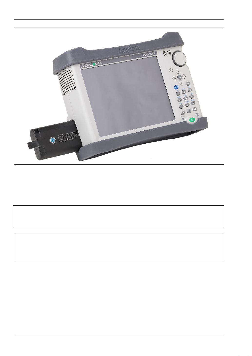
Figure 1-1. Battery Compartment
The battery that is supplied with the Cell Master may need charging before use. The battery
can be charged while it is installed in the Cell Master by using the AC-DC Adapter, or outside
the Cell Master with the optional Dual Battery Charger. Refer to “Symbols and Indicators”
on page 2-9 for a description of battery symbols.
Use only Anritsu Company approved batteries, adapters, and chargers with this
Note
instrument. Anritsu recommends removing the battery for long-term storage of the
instrument.
When using the Automotive Power Adapter, always verify that the supply is rated
Caution
for a minimum of 60 Watts @ 12 VDC, and that the socket is clear of any dirt or
debris. If the adapter plug becomes hot to the touch during operation, discontinue
use immediately.
1-8 PN: 10580-00250 Rev. AA Cell Master UG
Page 15

General Information 1-7 Secure Environment Workplace
1-7 Secure Environment Workplace
This section details the types of memory in the Cell Master, how to delete stored user files in
internal memory, and recommended usage in a secure environment workplace.
Cell Master Memory Types
The instrument contains non-volatile disk-on-a-chip memory, EEPROM, and volatile DRAM
memory. The instrument does not have a hard disk drive or any other type of volatile or
non-volatile memory.
Disk-On-A-Chip (DOC): DOC is used for storage of instrument firmware, factory calibration
information, user measurements, setups, and .jpg screen images. User information stored on
the DOC is erased by the master reset process described below.
EEPROM: This memory stores the model number, serial number, and calibration data for the
instrument. Also stored here are the user-set operating parameters such as frequency range.
During the master reset process, all operating parameters stored in the EEPROM are set to
standard factory default values.
RAM Memory: This is volatile memory used to store parameters needed for the normal
operation of the instrument along with current measurements. This memory is reset
whenever the instrument is restarted.
External USB Flash Drive (not included with the instrument): This memory may be selected
as the destination for saved measurements and setups for the instrument. The user can also
copy the contents of the internal disk-on-chip memory to the external flash memory for
storage or data transfer. The external Flash USB can be reformatted or sanitized using
software on a PC.
Refer to the Chapter 4, “File Management” for additional information on saving and copying
files to the USB flash drive.
Erase All User Files in Internal Memory
Perform a Master Reset:
1. Turn the instrument on.
2. Press the Shift button, then the System (8) button.
3. Press the System Options submenu key.
4. Press the Reset key, then the Master Reset key.
A message box will be displayed to warn the user that all settings will be returned to
factory default values and all user files will be deleted. This is a standard file deletion
and does not involve overwriting existing information.
5. Press the ENTER button to complete the master reset.
6. The instrument will reboot and the reset is complete.
Cell Master UG PN: 10580-00250 Rev. AA 1-9
Page 16

1-7 Secure Environment Workplace General Information
Recommended Usage in a Secure Environment
Set the instrument to save files to the external USB Flash drive:
1. Attach the external Flash drive and turn the instrument on.
2. Press the Shift button, then the File (7) button.
3. Press the Save submenu key.
4. Press the Change Save Location submenu key, then select the USB drive with the
rotary knob, Up/Down arrow keys, or the touch screen.
5. Press the Set Location submenu key.
The external USB drive is now the default location for saving files.
Not all USB drives are compatible with the instrument. Many drives come with a
second partition that contains proprietary firmware. This partition must be
Note
removed. Only one partition is allowed. Refer to the individual manufacturer for
instructions on how to remove it. Some drives can be made to work by reformatting
them using the FAT32 format.
1-10 PN: 10580-00250 Rev. AA Cell Master UG
Page 17
Chapter 2 — Instrument Overview
2-1 Introduction
This chapter provides an overview of the Anritsu Cell Master. It describes the instrument
front panel, touch screen display, and the connector panel. For detailed information on the
instrument’s test and measurement functions, refer to one of the Anritsu user documents
listed in Appendix A, “Measurement Guides”.
2-2 Turning On the Cell Master
The Anritsu Cell Master is capable of approximately three hours of continuous operation from
a fully charged, field-replaceable battery (refer to “Battery Replacement” on page 1-7). The
Cell Master can also be operated from a 12 VDC source (which will simultaneously charge the
battery). This can be achieved with either the Anritsu AC-DC Adapter or the Automotive
Power Adapter. Both items are included as standard accessories with the Cell Master. Refer
to the instrument Technical Data Sheet.
When using the Automotive Power Adapter, always verify that the supply is rated
Caution
for a minimum of 60 Watts @ 12 VDC, and that the socket is clear of any dirt or
debris. If the adapter plug becomes hot to the touch during operation, discontinue
use immediately.
To turn on the Cell Master, press the green On/Off button on the front panel (see Figure 2-1
on page 2-2).
The Cell Master takes approximately 60 seconds to complete power-up and to load the
application software. At the completion of this process, the instrument is ready for use.
Note
Keep the fan inlet and exhaust port clear of obstructions at all times for proper
ventilation and cooling of the instrument.
Cell Master UG PN: 10580-00250 Rev. AA 2-1
Page 18
2-3 Instrument Front Panel Instrument Overview
1
2
3
4
5
6
7
8
9
10
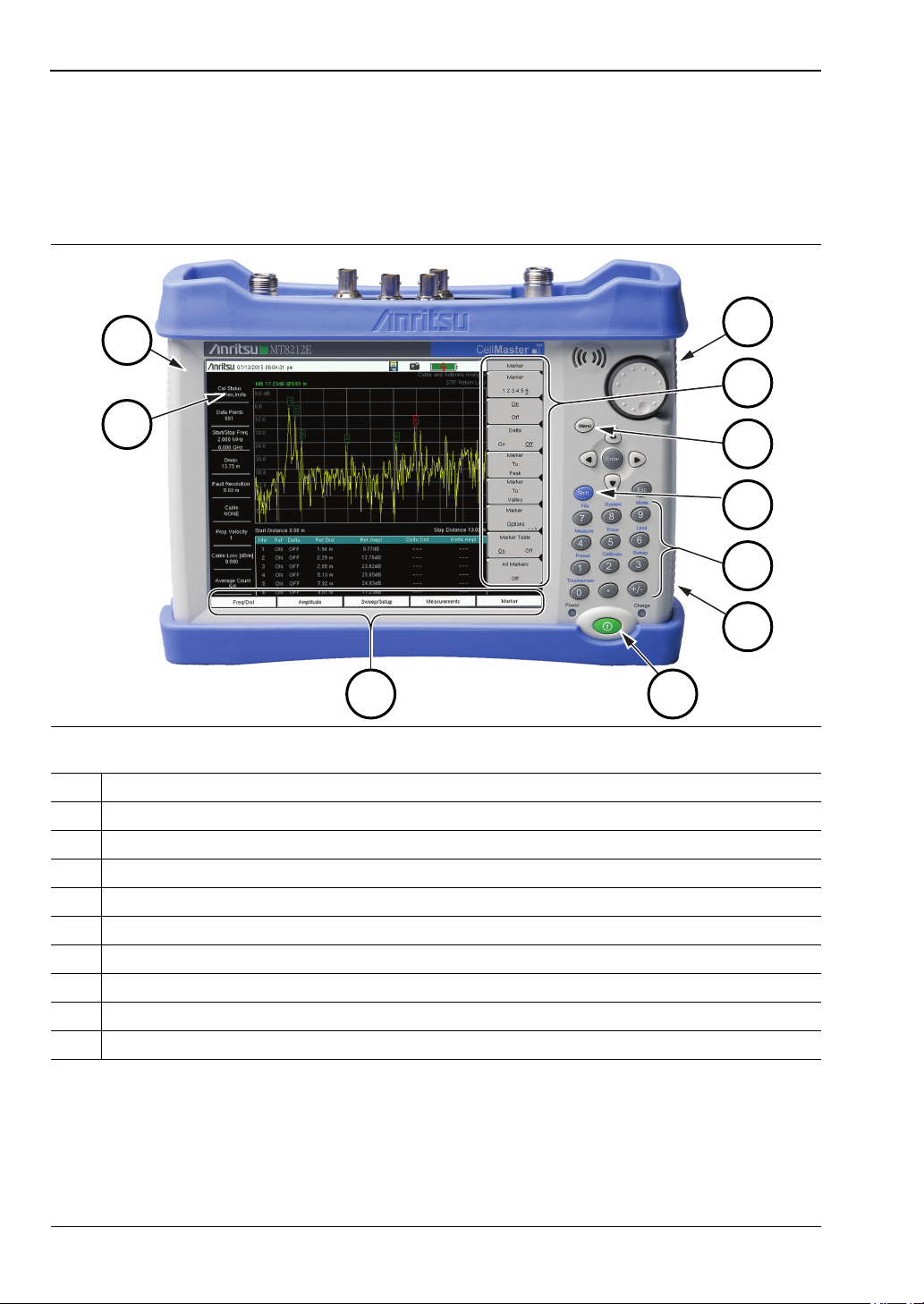
2-3 Instrument Front Panel
The Cell Master uses a touch screen and keypad for data input. See Figure 2-1. The five
bottom menu keys and up to eight submenu keys on the right side of the display are touch
screen keys. The menu and submenu keys vary depending on the current measurement mode,
installed options, and instrument function selected.
Figure 2-1. Cell Master Front Panel and Interface Screen
1. Fan Inlet Port
2. Touch Screen Submenu Keys
3. Menu Key
4. Shift Key
5. Numeric Keypad and Shift Menu Keys (0 to 9, printed in blue above each key)
6. Fan Inlet Port
7. On/Off Button
8. Touch Screen Main Menu Keys
9. Calibration Status and Type
10. Fan Exhaust Port
2-2 PN: 10580-00250 Rev. AA Cell Master UG
Page 19
Instrument Overview 2-3 Instrument Front Panel
LED Indicators
Power LED
The Power LED is located on the left of the On/Off button. The LED is solid green when the
instrument is on, and blinks slowly when the unit is off but is connected to an external power
source.
Charge LED
The Charge LED is located on the right of the On/Off button. The LED blinks slowly when the
battery is charging and is solid green when the battery is fully charged.
Front Panel Keys
The numeric keypad, rotary knob, and the four arrow keys can all be used to change the value
of the currently selected parameter.
Numeric Keypad
Keys 0 through 9 are used for numeric input, with an alternate function printed in blue above
each of the keys. Press the Shift key, then a numeric key, to access the instrument menu or
function indicated by the key label.
Some of the alternate functions associated with the numeric keypad are not available in all
measurement modes. Refer to the Measurement Guides listed in Appendix A.
Shift Key
Pressing the Shift key followed by a number key executes the function that is indicated in
blue above the number key. When the Shift key is active, its icon is displayed at the far right
of the title bar, above the sweep window.
Figure 2-2. Shift Key Icon in Title Bar
Esc Key
Press this key to cancel the parameter change being made and exit the current menu
function, if applicable.
Arrow Keys
The four arrow keys are used to scroll through a list and highlight the item you wish to select,
or to change the value of the currently selected parameter. The arrow keys can also be used to
move markers. The rotary knob performs similar functions.
Enter Key
Press this key to apply a parameter value or instrument setting you have entered, or to select
a highlighted item from a list.
Cell Master UG PN: 10580-00250 Rev. AA 2-3
Page 20
2-3 Instrument Front Panel Instrument Overview
Rotary Knob
Turn the rotary knob to change numerical values, scroll through selectable items in a list, or
to move markers. Values or items may be within a dialog box or an edit window.
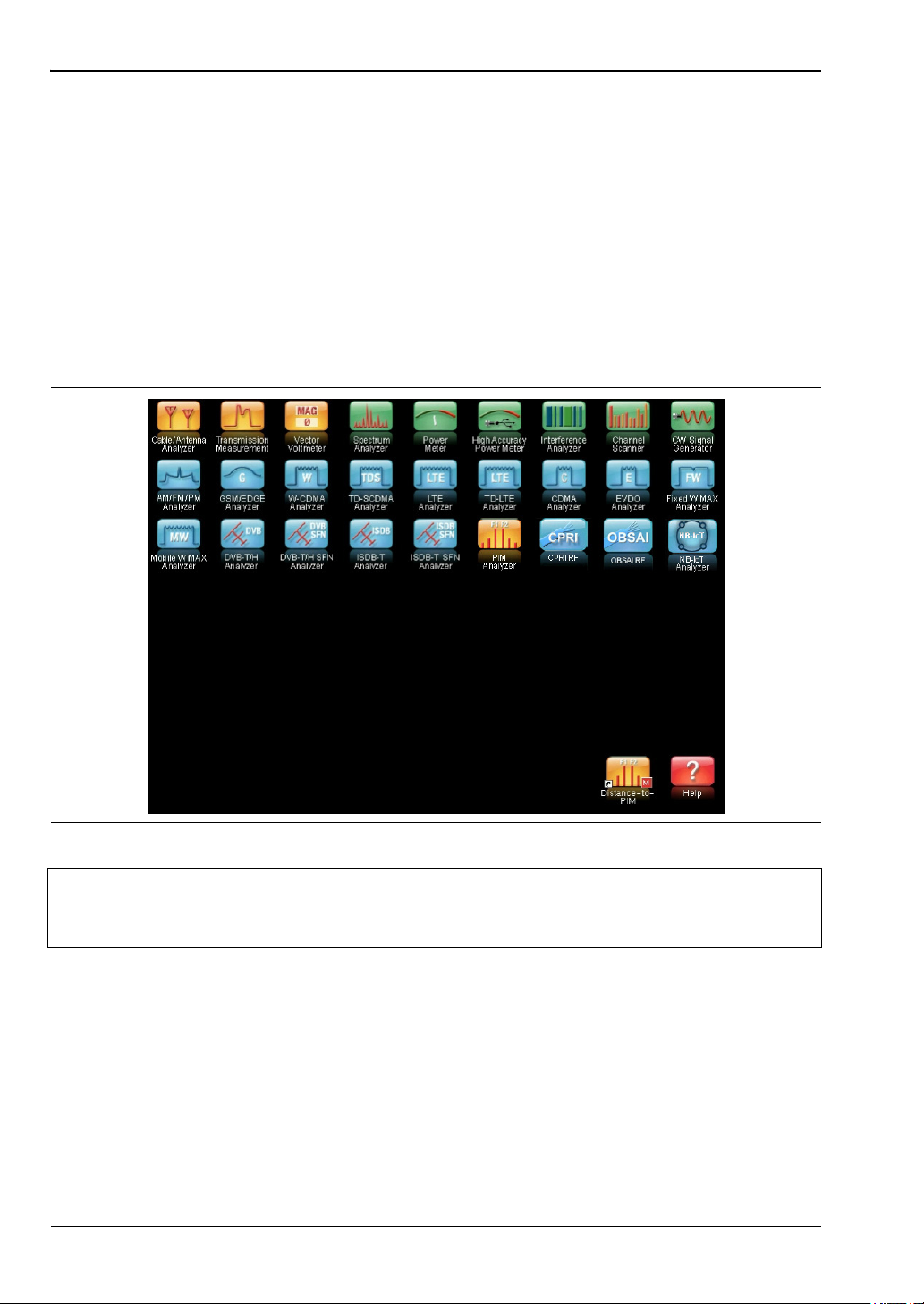
Menu Key
The Menu key displays a grid of shortcut icons for installed measurement modes and
user-selected menus and setup files. See Figure 2-3. Press one of the icons in the top rows to
switch to the corresponding application. These icons are system-generated and cannot be
moved or deleted.
An alternative to the Menu key is to press Shift, then the Mode (9) key to display the Mode
Selector list box. Refer to “Mode Selector” on page 2-16.
Figure 2-3. Menu Key Screen
Shortcut icons displayed in the top rows of the Menu screen vary with the
Note
instrument model, firmware version, and installed options. Help for the Menu
screen is available by pressing the icon in the lower right corner of the display.
2-4 PN: 10580-00250 Rev. AA Cell Master UG
Page 21
Instrument Overview 2-3 Instrument Front Panel
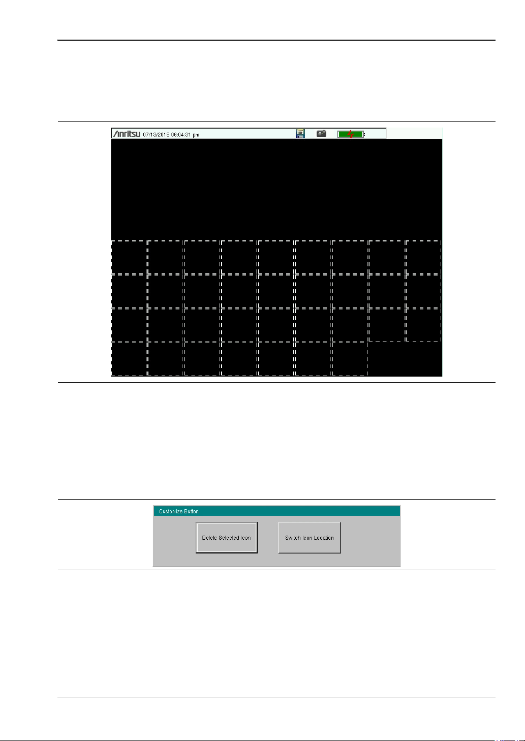
User-Created Shortcuts
To create a shortcut to any submenu key or main menu key, press and hold the key until a
grid appears, showing the open locations on the Menu screen where you can place the new
shortcut. Press one of the cells in the displayed grid to place the shortcut. See Figure 2-4.
Figure 2-4. Placement Grid for User-Created Shortcuts
To create a shortcut to a setup file (.stp), press Recall under the File menu, then press and
hold the desired file name until a grid is displayed. Select the display location of the new
shortcut as described above.
User-defined shortcuts remain on the Menu screen until deleted. To delete or move a shortcut
icon, press the Menu key, then press and hold the shortcut until the Customize Button dialog
appears. See Figure 2-5. Press the appropriate button to delete or move the shortcut icon.
Figure 2-5. Customize Button Dialog
Press Esc to close the dialog without deleting or moving the shortcut. Also use Esc to exit the
Menu screen.
Cell Master UG PN: 10580-00250 Rev. AA 2-5
Page 22
2-4 Interface Screen Instrument Overview
1
2
3
4
5 6
7
8
9
10
11
1213
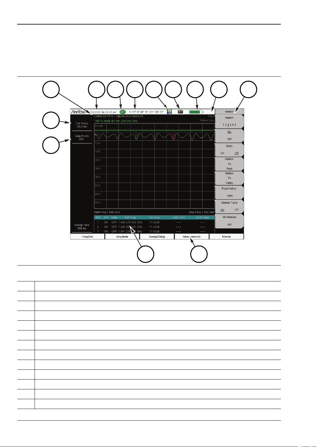
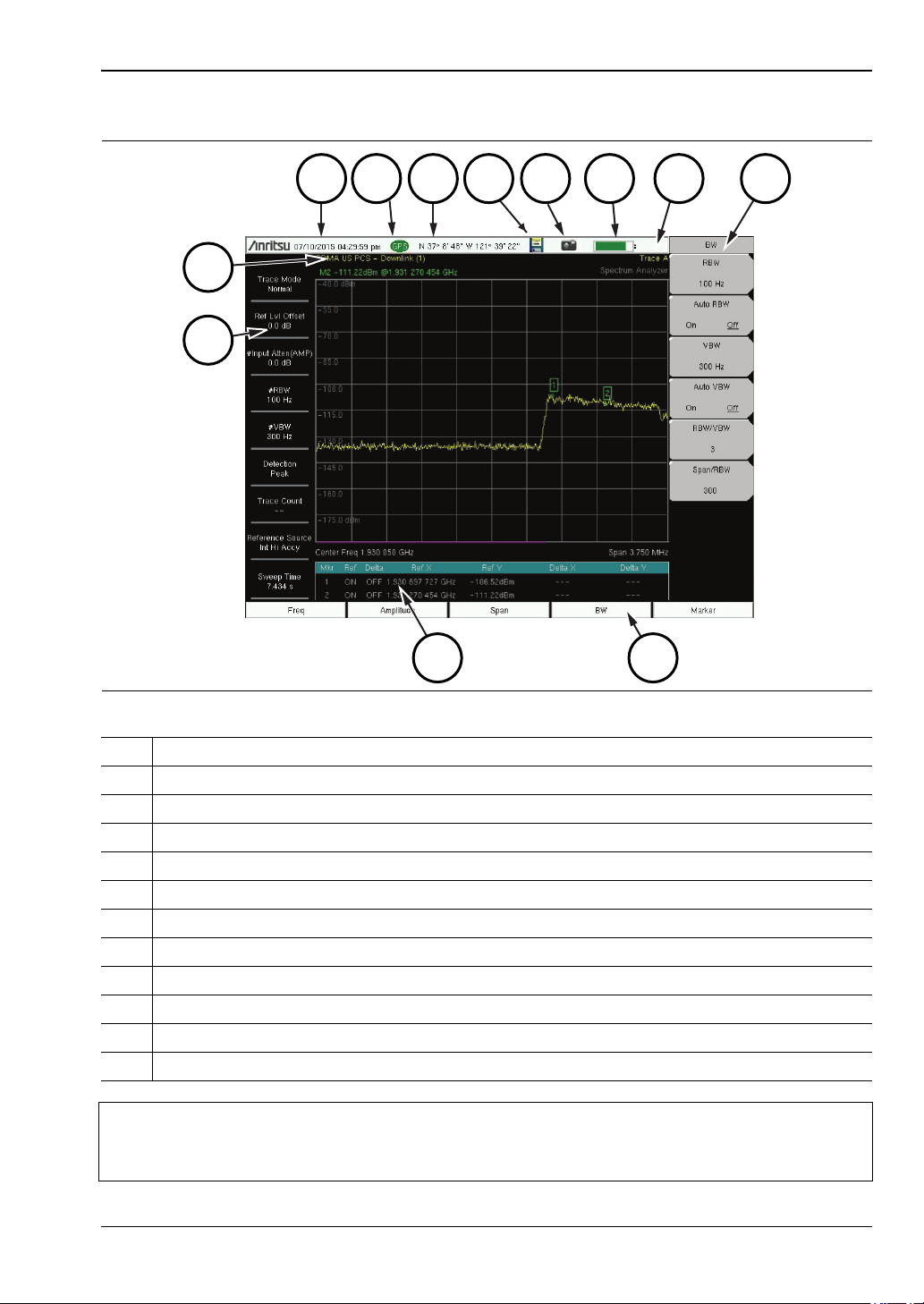
2-4 Interface Screen
Figure 2-6 and Figure 2-7 illustrate the Cell Master interface screen in Cable & Antenna
mode and Spectrum Analyzer mode, with touch screen menu keys, title bar, and
measurement settings and results around the graph area, or sweep window.
Figure 2-6. Cable & Antenna Analyzer Return Loss Measurement Display
1. Measurement Settings Summary
2. Calibration Status, Type
3. Frequency Standard
4. Date and Time
5. GPS Icon
6. GPS Location
7. Save Icon
8. Save Screen Icon
9. Battery Charge Indicator
10. Trace Measurement Title
11. Submenu Touch Screen Keys
12. Main Menu Touch Screen Keys
13. Marker Table
2-6 PN: 10580-00250 Rev. AA Cell Master UG
Page 23
Instrument Overview 2-4 Interface Screen
1
2
1112
3
4 5
6
7
8
9
10
Figure 2-7. Spectrum Analyzer Display
1. Measurement Settings Summary (Touch Screen Shortcuts)
2. Frequency Standard
3. Date and Time
4. GPS Icon
5. GPS Location
6. Save Icon
7. Save Screen Icon
8. Battery Charge Indicator
9. Trace Measurement Title
10. Submenu Touch Screen Keys
11. Main Menu Touch Screen Keys
12. Marker Table
Note
Many of the measurement settings displayed to the left and the top of the sweep
window are actually touch screen shortcuts that you can press to bring up the
corresponding menu.
Cell Master UG PN: 10580-00250 Rev. AA 2-7
Page 24
2-4 Interface Screen Instrument Overview
Touch Screen Keys
Main Menu Touch Screen Keys
There are five main menu keys horizontally arranged along the bottom of the interface
screen. These keys give access to the instrument’s test and measurement functions, which are
documented in the applicable Measurement Guide. Refer to Appendix A, “Measurement
Guides”.
Different operation or measurement modes may display different main menu keys. To switch
to another mode, press the Menu key, or press Shift followed by the Mode (9) key.
Note
Submenu Touch Screen Keys
Most of the instrument setup, control, and measurement functions are performed through the
use of the submenu keys along the right side of the display. The key labels change as
measurement settings and instrument setup parameters change. The current submenu title
is displayed at the top of the submenu key block, which consists of up to eight touch screen
keys. See Figure 2-6 on page 2-6.
The instrument model and installed options determine what measurement modes
are available. Refer to Table 1-1 and Table1-2 onpage1-4.
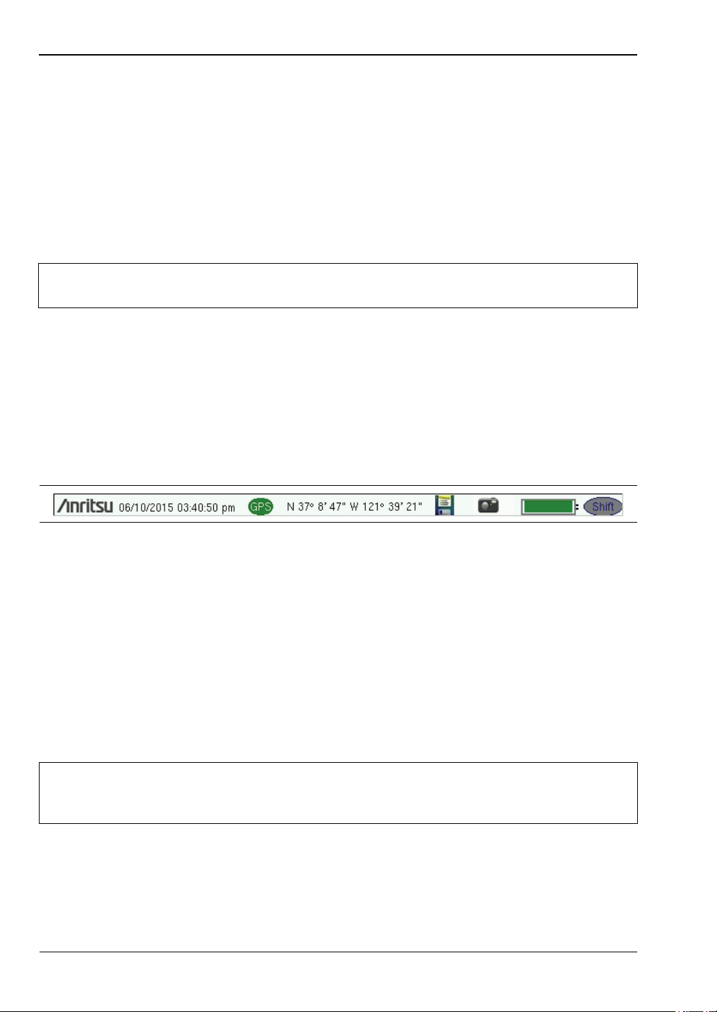
Symbols and Icons on the Title Bar
Figure 2-8. Title Bar with Icons
The instrument title bar displays the system date and time. When GPS is on and is tracking
satellites, its icon is followed by latitude and longitude coordinates.
Press the storage icon to open the touch screen keyboard for saving measurements, setups,
limit lines, or screen display JPEG files. This shortcut to the “Save Menu” on page 4-11 is
equivalent to pressing Shift and File (7), then Save. Refer to “Save Dialog Box” on page 4-3.
Press the camera icon to save a JPEG image of the current screen display.
The battery symbol indicates the charge remaining in the battery. The colored section inside
the symbol changes size and color with the charge level. The Battery Charge LED (adjacent to
the On/Off button) flashes when the battery is charging, and remains on steady when the
battery is fully charged.
Use only Anritsu-approved batteries, adapters, and chargers with this instrument.
Caution
The Shift icon is displayed after the Shift key is pressed, and it remains displayed until
another button is pressed.
2-8 PN: 10580-00250 Rev. AA Cell Master UG
Anritsu Company recommends removing the battery for long-term storage of the
instrument.
Page 25
Instrument Overview 2-4 Interface Screen
Shift
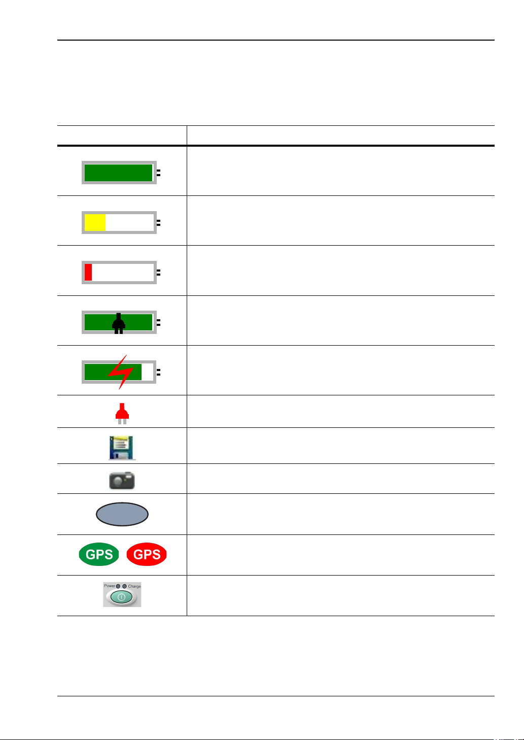
Symbols and Indicators
The following symbols, icons, and indicators convey the instrument status or condition on the
display. The colors shown here are in the standard or default display mode.
Table 2 - 1. Symbols and Icons
Symbol Description
Green: Battery is 30% to 100% charged.
Yellow: Battery is 10% to 30% charged.
Red: Battery is 0% to 10% charged.
Green with Black Plug body: Battery is fully charged and
external power is applied.
Lightning Bolt: Battery is being charged (any color symbol).
Red Plug body: External power is applied, and no battery is
installed, or battery has lost communications with the instrument.
Storage Icon: Tap the floppy disk icon to display the Save screen
and menu.
Camera Icon: Saves a JPEG image of the current screen display.
Shift Key Icon: This icon is displayed between the battery symbol
and the submenu keys after the Shift key has been pressed, and
until another key is pressed.
GPS Icon: This icon is displayed right after the date and time
when GPS is available. Refer to Chapter 6, “GPS (Option 31) ” for
details.
Power Button with Power LED and Charge LED: This is a
physical button with LED indicators. It is located near the numeric
keypad.
Cell Master UG PN: 10580-00250 Rev. AA 2-9
Page 26
2-4 Interface Screen Instrument Overview
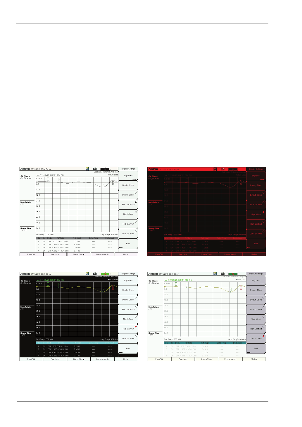
Black on White Night Vision
Color on WhiteHigh Contrast
Display Settings
The Display Settings submenu lets you adjust the screen brightness level and control the
auto-dimming function. Refer to “Brightness Settings Menu” on page 5-8.
You can also turn off the display entirely, as described in “Display Settings Menu”
on page 5-7. To turn the display back on, press any key (except the Power button) three times
in rapid succession.
In addition to the default display colors shown in Figure 2-6 on page 2-6, you can select
different color schemes to suit the ambient lighting conditions. See Figure 2-9. Some color
settings may not be available in all measurement modes.
Black on White — used for printing and viewing in broad daylight conditions
Night Vision — optimized for nighttime viewing
High Contrast — used in challenging viewing conditions
Color on White — used for printing and viewing in broad daylight conditions
Figure 2-9. Cell Master Display Color Settings
2-10 PN: 10580-00250 Rev. AA Cell Master UG
Page 27
Instrument Overview 2-4 Interface Screen
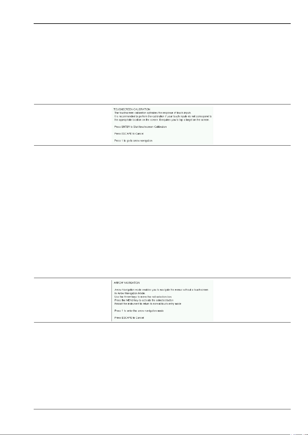
Touch Screen Calibration
Calibration optimizes the response of touch input. It is recommended if the instrument does
not respond as expected when you press the touch screen.
The Calibrate Touch Screen submenu key is in the “System Menu” on page 5-3. When pressed,
a message box is displayed with instructions for calibration. See Figure 2-10. Press Enter to
begin calibration, or press Esc to cancel. Alternatively, you can press 1 while the message box
is displayed to use the arrow keys for navigation. Refer to “Disable Touch Screen to Use
Arrow Navigation”.
Figure 2-10. Touch Screen Calibration Message Box
During calibration, press the crosshairs in sequence as they appear on the screen. The
process takes less than one minute.
Calibrate Touch Screen Shortcut
Another way to access touch screen calibration is to press Shift, then 0 (zero). This displays
the touch screen calibration message box shown in Figure 2-10. The shortcut can be used if
your touch inputs do not correspond to the appropriate locations on the screen to such an
extent that you cannot access the Calibrate Touch Screen submenu key.
Disable Touch Screen to Use Arrow Navigation
If the touch screen is not functioning, you can use Arrow Navigation to simulate pressing the
touch screen main menu keys and submenu keys. From the touch screen calibration message
box (see Figure 2-10), press 1 to display the arrow navigation message box, illustrated in
Figure 2-11. Press 1 again to enter the arrow navigation mode, or press Esc to cancel.
Figure 2-11. Arrow Navigation Message Box
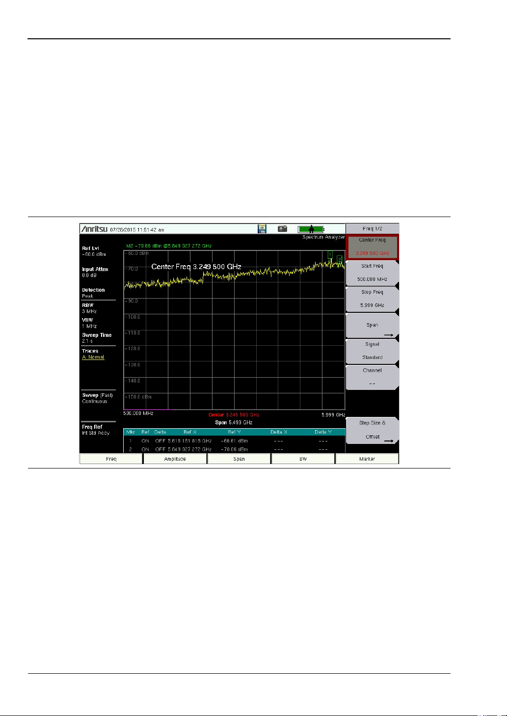
In arrow navigation mode, a red border highlights the currently selected key (see Figure 2-12
on page 2-12). Use the arrow keys to move the red selection box, then press the Menu key to
activate the highlighted key. Only the main menu keys and submenu keys can be activated
using Arrow Navigation. This feature does not move the red selection box into other areas of
the touch screen, like the display title bar, sweep window, or the instrument settings area on
the left.
Cell Master UG PN: 10580-00250 Rev. AA 2-11
Page 28
2-4 Interface Screen Instrument Overview
To save a measurement in arrow navigation mode, press Shift then File (7). Use the arrow
keys to move the red selection box to the Save Measurement As submenu key. This submenu
key must be used because the arrow navigation mode cannot be used to change data in popup
windows in the measurement display. File names are determined by the current setting of the
Save Measurement As submenu key. Refer to “Save Measurement As” on page 4-10.
You can save a JPEG image of the current display screen by pressing Shift, followed by
Decimal, then +/–. The JEPG image shows screen data, but does not contain the additional
measurement information that accompanies a saved measurement in a *.spa measurement
file.
To return to normal touch entry mode, reboot the instrument (turn power Off, then On). If
your touch screen has been damaged, refer to “Contacting Anritsu for Sales and Service”
on page 1-3.
Figure 2-12. Arrow Navigation Example
2-12 PN: 10580-00250 Rev. AA Cell Master UG
Page 29

Instrument Overview 2-4 Interface Screen
Calibration Symbols
The current calibration status and type are displayed in the upper-left of the screen when in
Cable & Antenna Analyzer mode. See Figure 2-6 on page 2-6. The five status messages are
described next.
Cal Status: ON, Flex
The Cell Master has been calibrated with discrete Open, Short, and Load components. This is
a FlexCal calibration indicating it is possible to change the frequency range after calibration.
Cal Status: ON, Standard
The Cell Master has been calibrated with discrete Open, Short, and Load components. This is
a Standard calibration indicating it is not possible to change the frequency range after
calibration without performing another calibration.
Cal Status: ON, Flex, Insta
The Cell Master has been calibrated with the InstaCal module. This is a FlexCal calibration
indicating it is possible to change the frequency range after calibration.
Cal Status: ON, Standard, Insta
The Cell Master has been calibrated with the InstaCal module. The Cell Master has been
calibrated with discrete Open, Short, and Load components. This is a Standard calibration
indicating it is not possible to change the frequency range after calibration without
performing another calibration.
Cal Status Off:
The Cell Master has not been calibrated.
For calibration procedures, refer to the Cable & Antenna Measurement Guide
(PN: 10580-00241) listed in Appendix A.
Cell Master UG PN: 10580-00250 Rev. AA 2-13
Page 30

2-5 Data Entry Instrument Overview
2-5 Data Entry
User input can be in the form of numeric values for instrument or measurement settings,
selected values from a preset list, or alphanumeric text when entering file names, for
example. To view or change a parameter value, access the appropriate submenu by pressing
one of the five main menu keys along the bottom of the interface screen, then navigating
through the touch screen submenus.
Other instrument functions are accessible from the numeric keypad, when used in
combination with the Shift key. Refer to “Numeric Keypad” on page 2-3. Some of the
parameter settings displayed on the left of the interface screen or under the title bar are
touch screen shortcuts to related submenus.
Depending on the measurement mode, refer to the associated Measurement Guide listed in
Appendix A for a description of available menus and submenus.
Numeric Values
To modify a numeric parameter setting that is displayed on a submenu touch screen key,
press the key to make it active. The display color of the currently set value changes to red.
Use the rotary knob, arrow keys, or the numeric keypad to change the value. When entering a
value from the keypad, the submenu typically shows the selectable units. Press the desired
unit or press Enter to complete the entry.
Selection Lists
Some parameters and instrument functions are selectable from a pop-up list. These list boxes
display the available selections, and value limits if applicable. Use the arrow keys or the
rotary knob to scroll through the list and highlight the desired entry. You can also use the
touch screen to make your selection.
To apply the selection, press Enter. To exit the selection list without making a change, press
the Escape (Esc) key.
2-14 PN: 10580-00250 Rev. AA Cell Master UG
Page 31

Instrument Overview 2-5 Data Entry
Text Entry
When an instrument function requires you to enter text, such as a name for a measurement
or setup file you wish to save, a touch screen keyboard is displayed. See Figure 2-13. Digits
can be entered using the touch screen keyboard or the front panel keypad. The left and right
arrow keys move the insertion point in the file name edit box.
Refer to “Save Dialog Box” on page 4-3 for information on saving files.
Figure 2-13. Touch Screen Keyboard
Cell Master UG PN: 10580-00250 Rev. AA 2-15
Page 32

2-6 Mode Selector Instrument Overview
2-6 Mode Selector
To change to another operation or measurement mode, press Shift, then the Mode (9) key to
display the Mode Selector list box, illustrated in Figure 2-14. Use the directional arrow keys
or the rotary knob to highlight the desired mode, then press Enter to switch to the selected
application. The measurement modes available for selection depend on the options that are
installed and activated on your instrument.
An alternate method of selecting a measurement mode is through the use of the “Menu Key”
on page 2-4.
Figure 2-14. Mode Selector List Box
2-16 PN: 10580-00250 Rev. AA Cell Master UG
Page 33

Instrument Overview 2-7 Connector Panel
CAUTION
AVOID STATIC
DISCHARGE
12.5-15 VDC (4A)
±50 VDC MAX
+23 dBm MAX
±5 VDC MAX
RF Out
/Reflection In
ȍ
RF In
±50 VDC MAX
+30 dBm MAX
ȍ
GPS
Optical
SFP
IEC 60825-1-2007
CLASS 1 LASER
1
3
7
6
10
8
2
4
9
5
11
2-7 Connector Panel
The Cell Master connector panel is illustrated in Figure 2-15.
Figure 2-15. Cell Master Connector Panel
1. External Reference In
2. External Trigger In, T1 E1 Ref. Freq.
3. RF In (Type N)
4. GPS Type SMA (Option 31)
5. USB Mini-B
6. RJ45 Ethernet Connector (Option 413)
7. External Power
8. USB Type A
9. Headset jack
10. Option 759
Options 57
Option 52
Option 51
a
or Option 751b: SFP Optical Module Connector
c
and 79c: DVB ASI Out Connector (see Figure 2-16)
b
: Rx, Tx, E1 Connectors
b
or Option 53b: RJ45 is replaced with Bantam Connectors (see Figure 2-17)
11. RF Out/Reflection In (Type N)
a.This option and Options 57 and 79 are mutually exclusive.
b.This option is obsolete.
c.This option and Option 759 are mutually exclusive.
Cell Master UG PN: 10580-00250 Rev. AA 2-17
Page 34

2-7 Connector Panel Instrument Overview
75 800mVpp
ASI Out
Figure 2-16. DVB ASI Out BNC Connector for BER Measurements (Option 57 and Option 79)
Figure 2-17. E1 Tx/Tx Connectors (Option 52, 51 or 53)
External Reference In
The External Reference In port is a 50 Ω BNC female connector that provides for input of an
external frequency reference. Refer to your Technical Data Sheet for valid frequencies. To
prevent damage to your instrument, do not use pliers or a wrench to tighten the BNC
connector.
External Trigger In
A TTL signal that is applied to the External Trigger 50 Ω female BNC input connector causes
a single sweep to occur. In the Spectrum Analyzer mode, it is used in zero span, and
triggering occurs on the rising edge of the signal. After the sweep is complete, the resultant
trace is displayed until the next trigger signal arrives.
Analyzer/RF In
50 Ω Type-N female connector. Maximum input is +33 dBm at ±50 VDC.
Headset Jack
The headset jack provides audio output from the built-in AM/FM/SSB demodulator for testing
and troubleshooting wireless communication systems. The jack accepts a 3.5 mm 3-wire
miniature phone plug such as those commonly used with cellular telephones.
2-18 PN: 10580-00250 Rev. AA Cell Master UG
Page 35

Instrument Overview 2-7 Connector Panel
USB Interface – Mini-B
The USB 2.0 Mini-B connector can be used to connect the Cell Master directly to a PC. The
first time the Cell Master is connected to a PC, the normal USB device detection by the
computer operating system will take place.
Note
For proper detection, the applicable Anritsu Software Tool should be installed on
the PC prior to connecting the Cell Master to the USB port.
GPS Antenna Connector (Option 31)
The GPS antenna connection on the Cell Master is type SMA-female. GPS function is
described in Chapter 6, “GPS (Option 31) ”.
To prevent damage to your instrument, do not use pliers or a plain wrench to tighten the
SMA connector. Do not over-tighten the connector. The recommended torque is 8 lbf·in
(0.9 N·m or 90 N·cm).
External Power
This is a 2.1 mm by 5.5 mm barrel connector, 12.5 to 15 VDC, < 4.0 A. The external power
connector is used to power the unit and for battery charging. A green blinking LED near the
Power button indicates that the instrument battery is being charged by the external charging
unit. The indicator is a steady green when the battery is fully charged.
When using the AC-DC Adapter, always use a three-wire power cable that is
Warning
connected to a three-wire power line outlet. If power is supplied without grounding
the equipment in this manner, then the user is at risk of receiving a severe or fatal
electric shock.
Refer to “External Power On” on page 3-12 and “Power-On Menu” on page 5-6 when
controlling the Cell Master via external power.
USB Interface – Type A
The Cell Master has two Type A USB connectors that accept USB Flash Memory devices for
storing measurements, setup data, and screen images.
Rx, Tx, E1 Connectors (Options 51, 52, 53)
These options are obsolete. The ports are used in T1/T3/E1 operations described in the
Backhaul Measurement Guide.
To avoid damaging your instrument, do not use pliers or a wrench to tighten the connectors.
Digital Signal Output (DVB ASI Out) BNC Connector (Options 57, 79)
The digital signal output, BNC female connector is unique to the Bit Error Rate (BER)
options (Option 57 and Option 79) and is present only when one or both of these options are
installed. The Digital Television Signal Analyzer options operations are described in the
Digital Television Signal Analyzer Measurement Guide (refer to Appendix A).
Cell Master UG PN: 10580-00250 Rev. AA 2-19
Page 36

2-7 Connector Panel Instrument Overview
To prevent damage to your instrument, do not use pliers or a wrench to tighten the BNC
connector. Do not over-tighten the connector.
The DVB-ASI function produces MPEG-TS data output during a BER measurement. This
output can be connected to MPEG-TS analysis equipment to monitor video errors or can be
connected via appropriate ASI to USB demultiplexing and decoding accessories for channel
identification and monitoring purposes.
LAN Connection (Option 413)
The RJ-45 connector is used to connect the Cell Master to a local area network or directly to a
PC with an Ethernet crossover cable. Integrated into this connector are two LEDs. The amber
LED shows the presence of a 10 Mbit/s LAN connection when on, and a 100 Mbit/s LAN
connection when off. The green LED flashes to show that LAN traffic is present. For more
information on the LAN connection, Ethernet connection, and DHCP. Refer to Chapter 9 and
Appendix B.
Optical SFP (Option 759)
The optical transceiver port is used to connect the instrument to the fiber optic CPRI or
OBSAI link between a Radio Frequency Module (RFM) and a Base Band Module (BBM). This
SFP port is present only when Option 759 (RF over Fiber hardware) is installed. Refer to the
instrument’s Technical Data Sheet for transceiver part numbers and specifications.
Option 759 requires either Option 752 (CPRI LTE RF Measurements) or
Note
Option 753 (OBSAI LTE RF Measurements). The combination of Option 759 and
Option 752 is functionally identical to obsolete Option 751.
RF Out (Reflection In)
RF output, 50 Ω Type-N female connector, for reflection measurements. Maximum input is
+23dBm at ±50VDC.
2-20 PN: 10580-00250 Rev. AA Cell Master UG
Page 37

Instrument Overview 2-8 Soft Carrying Case
2-8 Soft Carrying Case
The Cell Master can be operated while in the soft carrying case. On the back of the case is a
large storage pouch for accessories and supplies.
To install the instrument into the soft carrying case:
1. The front panel of the case is secured with hook-and-loop fasteners. Fully close the
front panel of the case. When closed, the front panel supports the shape of the case
while you are inserting the Cell Master.
2. Place the soft carrying case face down on a stable surface, with the front panel fully
closed and laying flat.
The soft case has two zippers near the back. The zipper closer to the front of the
case opens to install and remove the instrument. The zipper closer to the back of
Note
3. Open the zippered back of the case.
4. Insert the instrument face down into the case, take care that the connectors are
properly situated in the case top opening. You may find it easier to insert the
connectors first, then pull the corners over the bottom of the Cell Master.
the case opens an adjustable support panel that can be used to provide support for
improved stability and air flow while the instrument is in the case. This support
panel also contains the storage pouch.
Figure 2-18. Instrument Inserted into the Soft Carrying Case
5. Close the back panel and zipper to secure the Cell Master.
Cell Master UG PN: 10580-00250 Rev. AA 2-21
Page 38

2-9 Tilt Bail Stand Instrument Overview
The soft carrying case includes a detachable shoulder strap, which can be connected to the
D-rings of the case.
Caution
The soft case has panel openings for the fan inlet and exhaust ports. Do not block
the air flow through the panels when the unit is operating.
2-9 Tilt Bail Stand
A Tilt Bail is attached to the back of the Cell Master for desktop operation. The tilt bail
provides two settings of backward tilt for improved stability. To deploy the tilt bail, pull the
bottom of the tilt bail away from the back of the instrument. To store the tilt bail, push the
bottom of the bail towards the back of the instrument until it attaches to the Cell Master.
Note
Do not use the tilt bail while the instrument is in the soft case. The soft case has an
adjustable support panel in the back zipper.
Figure 2-19. Tilt Bail Extended
2-22 PN: 10580-00250 Rev. AA Cell Master UG
Page 39

Quick Start Guide 3-1 Introduction
Chapter 3 — Quick Start Guide
3-1 Introduction
This chapter provides a brief overview of basic setups for the following measurement modes:
• “Cable & Antenna Analyzer” on page 3-2
• “Spectrum Analyzer” on page 3-8
For detailed descriptions of measurement functions and settings, refer to the appropriate
Measurement Guide as listed in Appendix A.
3-2 Measurement Mode Selection
Press the Menu key, then press the shortcut icon for the desired application, or measurement
mode. See Figure 3-1. Alternatively, you can press Shift followed by the Mode (9) key, then
select the measurement mode from the Mode Selector list box.
Figure 3-1. Menu Screen - Shortcuts to Installed Applications
Note
Cell Master UG PN: 10580-00250 Rev. AA 3-1
The application shortcuts displayed in the top rows of the Menu screen will vary
depending on the firmware and options installed on the instrument.
Page 40

3-3 Cable & Antenna Analyzer Quick Start Guide
3-3 Cable & Antenna Analyzer
Set the instrument to Cable & Antenna Analyzer mode as described in the previous section.
Select the Measurement Type
Press the Measurements main menu key and select the appropriate measurement.
Figure 3-2. Measurement Screen
Set the Frequency
1. Press the Freq/Dist main menu key.
2. Press the Start Freq submenu key and use the numeric keypad, rotary knob, or the
arrow keys to enter the start frequency.
3. Press the Stop Freq submenu key and enter the stop frequency.
Set the Amplitude
1. Press the Amplitude main menu key.
2. Press the To p submenu key and use the numeric keypad, rotary knob, or the arrow keys
to adjust the top scale value as needed.
3. Press the Bottom submenu key and change the bottom scale value if needed.
Note
3-2 PN: 10580-00250 Rev. AA Cell Master UG
For Amplitude in Smith Chart measurements, refer to “Smith Chart” in the Cable &
Antenna Measurement Guide listed in Appendix A.
Page 41

Quick Start Guide 3-3 Cable & Antenna Analyzer
Turn on Markers
1. Press the Marker main menu key.
2. Press the Marker 1 2 3 4 5 6 submenu key and select the marker number 1 button using
the touch screen. The underlined number on the Marker submenu key indicates the
active marker.
3. Use the arrow keys, the keypad, or the rotary knob to move the marker. The current
value for the selected marker is shown above the upper-left corner of the graph. It is
also possible to drag the marker using the touch screen.
4. Delta Markers are available for each of the six reference markers. For the selected
marker, Toggle the Delta On/Off submenu key to turn on the Delta marker.
Peak/Valley Auto Markers
When making Return Loss and VSWR measurements, the Peak/Valley Auto feature can be
used to automatically turn on Marker 1 to peak, Marker 2 to valley, and display M1 and M2
in the Marker Table. This feature is not available for DTF measurements.
1. Press the Marker main menu key.
2. Press the Peak/Valley Auto key.
Cell Master UG PN: 10580-00250 Rev. AA 3-3
Page 42

3-3 Cable & Antenna Analyzer Quick Start Guide
Single Limit Line
1. Press Shift, then Limit (6) to display the Limit menu.
2. Press the Limit On/Off key to turn on the Limit.
3. Press Single Limit and then use the numeric keypad, the arrow keys, or the rotary knob
to change the limit value and then press Enter.
Note
4. Press the Limit Alarm key to turn on or off the Limit Alarm.
Refer to the Cable & Antenna Measurement Guide listed in Appendix A for
creating multi-segment limit lines.
Figure 3-3. Single Limit Lines
3-4 PN: 10580-00250 Rev. AA Cell Master UG
Page 43

Quick Start Guide 3-3 Cable & Antenna Analyzer
DTF Setup
1. Press the Measurements main menu key and select DTF Return Loss or DTF VSWR.
2. Press the Freq/Dist main menu key.
3. Press the Units submenu key and select m to display distance in meters or ft to display
distance in feet.
4. Press DTF Aid and use the touch screen or arrow keys to navigate through all the DTF
parameters.
a. Set Start Distance and Stop Distance. Stop Distance needs to be smaller than
Dmax.
b. Enter the Start and Stop frequencies.
c. Press Cable, select the appropriate cable from the cable list and press Enter.
d. Press Continue.
Figure 3-4. DTF Aid
5. Press Shift, then Calibrate (2) to calibrate the instrument. Refer to “Calibrate with OSL
Calibration” on page 3-6 for additional information.
6. Press the Marker main menu key and set the appropriate markers.
7. Press Shift and Limit (6) to enter and set the appropriate limit lines.
8. Press Shift and File (7) to save the measurement. See the User Guide for details.
Cell Master UG PN: 10580-00250 Rev. AA 3-5
Page 44

3-3 Cable & Antenna Analyzer Quick Start Guide
Calibrate with OSL Calibration
Note
1. Press the Freq/Dist main menu key and enter the appropriate frequency range
2. Press Shift, followed by Calibrate (2).
3. Select Standard or FlexCal.
4. Press Start Cal and follow instructions on screen.
5. Connect Open to RF Out and press the Enter key.
6. Connect Short to RF Out and press the Enter key.
7. Connect Load to RF Out and press the Enter key.
8. Verify that the calibration has been properly performed by checking that the Cal Status
message is now displaying “ON, Standard” or “ON, FlexCal”.
Refer to the Cable & Antenna Measurement Guide listed in Appendix A for
calibration details.
3-6 PN: 10580-00250 Rev. AA Cell Master UG
Page 45

Quick Start Guide 3-3 Cable & Antenna Analyzer
OPEN
LOAD
SHORT
Power Charge
+/-
.
0
3
Sweep
2
Calibrate
1
Preset
6
Limit
5
Trace
4
Measure
9
Mode
8
System
7
File
Shift
Esc
Enter
Menu
CellMaster
MT8212E
CALIBRATION
RF OUT/
REFLECTION
Test Port
TEST PORT CABLE
(OPTIONAL)
1
3
2
4
Figure 3-5. Calibration Setup with OSL Cal
1. RF Out / Reflection Test Port
2. Test Port Cable (Optional)
3. Calibration Components (Open, Short, Load)
4. Calibration Test Connection
Cell Master UG PN: 10580-00250 Rev. AA 3-7
Page 46

3-4 Spectrum Analyzer Quick Start Guide
3-4 Spectrum Analyzer
Set the instrument to Spectrum Analyzer mode as described in Section 3-2 “Measurement
Mode Selection” on page 3-1.
Set Start and Stop Frequencies
1. Press the Freq main menu key.
2. Press the Start Freq submenu key.
3. Enter the desired start frequency using the keypad, the arrow keys, or the rotary knob.
When entering a frequency using the keypad, the submenu key labels change to GHz,
MHz, kHz, and Hz. Press the appropriate unit key. Pressing the Enter key has the same
effect as pressing the MHz submenu key.
4. Press the Stop Freq submenu key.
5. Enter the desired stop frequency.
Enter the Center Frequency
1. Press the Freq main menu key.
2. Press the Center Freq submenu key.
3. Enter the desired center frequency using the keypad, the arrow keys, or the rotary
knob. When entering a frequency using the keypad, the submenu key labels change to
GHz, MHz, kHz, and Hz. Press the appropriate unit key. Pressing the Enter key has the
same effect as pressing the MHz submenu key.
The center frequency and span is shown at the bottom of the screen.
Select a Signal Standard
1. Press the Freq main menu key.
2. Press the Signal Standard submenu key. The Signal Standards dialog box opens.
3. Highlight a signal standard and press Enter to select.
4. Press the Channel submenu key to change the channel value in the Channel Editor.
The signal standard is shown in yellow at the top of the screen.
Set the Measurement Frequency Bandwidth
1. Press the BW main menu key to display the BW menu.
• Press the RBW and/or the VBW submenu key to manually change the values.
• Set RBW and VBW automatically by pressing the Auto RBW submenu key or the
Auto VBW submenu key.
2. Press the RBW/VBW submenu key to change the resolution bandwidth and video
bandwidth ratio.
3. Press the Span/RBW submenu key to change the span width to resolution bandwidth
ratio.
3-8 PN: 10580-00250 Rev. AA Cell Master UG
Page 47

Quick Start Guide 3-4 Spectrum Analyzer
Set the Amplitude
Press the Amplitude main menu key to display the Amplitude menu.
Set Amplitude Reference Level and Scale
1. Press the Reference Level submenu key and use the arrow keys, rotary knob, or the
keypad to change the reference level. Press Enter to set the reference level value.
2. Press the Scale submenu key and use the arrow keys, rotary knob, or the keypad to
enter the desired scale. Press Enter to set the scale value.
Set Amplitude Range and Scale
1. Press the Auto Atten submenu key to set an optimal reference level based on the
measured signal.
2. Press the Scale submenu key.
3. Enter the desired scale units by using the keypad, the arrow keys, or the rotary knob.
Press Enter to set. The y-axis scale is automatically renumbered.
Power Offset Set Up for Compensating External Loss
To obtain accurate results, compensate for any external attenuation by using power offset.
In power offset mode, the compensation factor is in dB. (External attenuation can be created
by using an external cable or an external high power attenuator.)
Press the RL Offset submenu key and use the keypad, the arrow keys, or the rotary knob to
enter the desired offset value. When using the rotary knob, the value changes in increments
of 0.1 dB. Using the Left/Right arrow keys changes the value in 10% increments of the value
shown on the Scale submenu key. When using the Up/Down arrow keys, the value changes in
the increment shown on the Scale submenu key. When using the keypad, enter the new value
then press Enter or the dB submenu key to set the value. The power offset is displayed in the
instrument settings summary column on the left side of the measurement display.
Set the Span
1. Press the Span main menu key or the Freq main menu key followed by the
Span submenu key.
2. To select full span, press the Full Span submenu key. Selecting full span overrides any
previously set Start and Stop frequencies.
3. For a single frequency measurement, press the Zero Span submenu key.
To quickly move the span value up or down, press the Span Up 1-2-5 or Span
Note
Cell Master UG PN: 10580-00250 Rev. AA 3-9
Down 1-2-5 submenu keys These keys facilitate a zoom-in, zoom-out feature in a
1-2-5 sequence.
Page 48

3-4 Spectrum Analyzer Quick Start Guide
Single Limit Line
Press the Limit menu key to display the Limit menu.
1. Press the Limit (Upper / Lower) submenu key to select the desired limit line,
Upper or Lower.
2. Activate the selected limit line by pressing the On Off submenu key so that On is
underlined.
3. Press the Limit Move submenu key to display the Limit Move menu. Press the first
Move Limit submenu key and use the arrows keys, rotary knob, or keypad to change the
dBm level of the limit line.
4. Press the Back submenu key to return to the Limit menu.
5. If necessary, press the Set Default Limit submenu key to redraw the limit line in view.
Create a Limit Envelope
1. Press Shift, then Limit (6) to display the Limit menu.
2. Select Limit Envelope.
3. Press the Create Envelope key.
Figure 3-6. Limit Envelope
3-10 PN: 10580-00250 Rev. AA Cell Master UG
Page 49

Quick Start Guide 3-4 Spectrum Analyzer
Setting Up Markers
Press the Marker main menu key to display the Marker menu.
Selecting, Activating, and Placing a Marker
1. Press the Marker 1 2 3 4 5 6 submenu key and select the desired marker using the touch
screen marker buttons. The selected marker is underlined on the Marker submenu key.
2. Press the On Off submenu key so that On is underlined. The selected marker is
displayed in red and ready to be moved.
3. Use the rotary knob to place the marker on the desired frequency.
4. Repeat steps 1 through 3 to activate and move additional markers.
Selecting, Activating, and Placing a Delta Marker
1. Press the Marker 1 2 3 4 5 6 submenu key and select the desired delta marker. The
selected marker is underlined.
2. Press the Delta On Off submenu key so that On is underlined. The selected marker is
displayed in red and ready to be moved.
3. Use the rotary knob to place the delta marker on the desired frequency.
4. Repeat steps 1 through 3 to activate and move additional markers.
Viewing Marker Data in a Table Format
1. Press the More submenu key.
2. Press the Marker Table On Off submenu key so that On is underlined. All marker and
delta marker data are displayed in a table under the measurement graph.
Figure 3-7. Marker Table
Cell Master UG PN: 10580-00250 Rev. AA 3-11
Page 50

3-4 Spectrum Analyzer Quick Start Guide
Select a Measurement Type
In Spectrum Analyzer mode, press Shift, then Measure (4) and select a measurement using
the submenu keys.
Figure 3-8. Spectrum Analyzer Measure Menu
External Power On
The When DC Applied setting in the Power-On menu allows the Cell Master to restart
automatically when external DC power is applied to the connector shown in Figure 2-15
on page 2-17. Refer to “External Power” on page 2-19 and the “Power-On Menu” on page 5-6.
When this feature is enabled, the Cell Master in the off state will turn on when external DC
power is applied. The instrument turns off when external power is removed, even if a battery
is installed. This is useful for high-reliability remote operation, where the instrument may
need to be rebooted using a remotely-controlled power switch.
If the instrument is turned on with the power switch, then external power is removed, the
instrument will continue to run until the battery is depleted. It will come on and the battery
will begin recharging when external power is applied. This state is useful when the
instrument is in a location where the power source may be interrupted.
3-12 PN: 10580-00250 Rev. AA Cell Master UG
Page 51

Chapter 4 — File Management
4-1 Introduction
This chapter describes the file management features of the Cell Master and the related touch
screen menus. The File menu and its submenus allow you to save, recall, copy, and delete files
in internal memory or an external USB flash drive.
4-2 Managing Files
Press the Shift key, then the File (7) key on the numeric keypad to display the File menu.
When navigating through the File menu, press the Esc key to return to the
Note
File Types
Under the Save, Recall, Copy, and Delete menus, press the Change Type or the File Type
submenu key to open the Select File Type list box, where you can select the desired file type.
Available file types depend on the current instrument mode. The Select File Type list box may
contain the following entries:
previous menu or submenu. Any changes not yet applied (by pressing Enter) are
canceled.
• ALL (displays all file types)
• Setup, *.stp
(Setup files contain basic instrument information, measurement mode setup details,
measurement marker data, and limit data.)
• Measurement, *.spa, *.dat, *.vna, *.ia, *.cs, *.edg, *.wcd, *.tds,
*.lte, *.tdlte, *.cdma, *.evdo, *.wmxd, *.wmxe, *.afp
(Measurement files contain all of the information in the setup files and the
measurement data. File extensions are determined by the current measurement mode
and selected file type.)
• JPEG, *.jpg
(Image file is a screen capture of the current measurement display.)
• Limit Lines, *.lim
(The Limit Line file contains limit line data details.)
• Spurious Emission Mask, *.spe
(The Spurious Emission Mask file contains the frequency, amplitude, and other
information related to segments in an out-of-band spurious emission mask.)
• KML 2D, *.kml
• KML 3D, *.kml
• Mapping Tab Delimited, *.mtd
You can also use the touch screen to open the drop down list for the Filetype entry box, as
shown in Figure 4-1 on page 4-2.
Cell Master UG PN: 10580-00250 Rev. AA 4-1
Page 52

4-2 Managing Files File Management
Save Files
The submenu keys that are available for file management may vary with instrument options
and measurement modes. Refer to “File Menu” on page 4-10.
Save Measurement As
The Save Measurement As submenu key provides a one-touch method of saving the current
measurement data. The name of the file that will be saved is displayed on the submenu key.
The numerical suffix increments by 1 following the Save. For example, if the last
measurement was saved with the file name ACPR, the Save Measurement As shows the
default file name for the next measurement to be saved as ACPR_1, then ACPR_2, and so on.
To save using a different file name than the default, press the Save Measurement key or the
Save key instead of Save Measurement As.
Save Measurement
To save the current measurement data, use the Save Measurement As submenu key described
above or, to apply a different file name or save location than the default, press the Save
Measurement submenu key or the Save key. In the Save dialog, you can enter the file name
and select the type of data to save. See Figure 4-1 and refer to “Save Dialog Box” on page 4-3.
Save
The Save submenu key has the same function as Save Measurement. It opens the Save dialog
box and menu illustrated in Figure 4-1.
Figure 4-1. Save Dialog Box
4-2 PN: 10580-00250 Rev. AA Cell Master UG
Page 53

File Management 4-2 Managing Files
Save Dialog Box
In the Save dialog, use the touch screen keyboard to enter the name of the file to save. See
Figure 4-1 on page 4-2. Optionally, you can use the Quick Name keys to insert preset text
strings into the file name. Refer to “Quick Name Keys”.
To select the type of data to save, either press the Filetype selection box to display the drop
down list of available file types, or press the Change Type submenu key. Selectable file types
vary with the measurement mode. Use the Up/Down arrow keys to highlight the desired file
type, then press Enter to select.
Press Enter again to save the file. File name extensions are automatically assigned based on
the file type and measurement mode. Refer to “File Types” on page 4-1.
Quick Name Keys
Quick Name keys in the Save dialog provide optional building blocks for entering file names.
They function as keyboard shortcuts, allowing you to enter predefined, frequently used file
names or parts of file names. To enter or change a Quick Name, press the Change Quick Name
submenu key in the Save menu, then select the item to edit (see Figure 4-2) and press Enter
on the numeric keypad. In the Edit Quick Name dialog, use the touch screen keyboard to
enter a new Quick Name. See Figure 4-3. Press Enter again and the new name will be
displayed on the key, in the Save dialog.
Figure 4-2. Select Quick Name List Box
Figure 4-3. Edit Quick Name Dialog Box
Cell Master UG PN: 10580-00250 Rev. AA 4-3
Page 54

4-2 Managing Files File Management
Quick Name Matrix
The Quick Name Matrix key is present in the Save dialog only in the Cable and Antenna
Analyzer and 2-port Transmission measurement modes. See Figure 4-4. Similarly to the Quick
Name keys, the matrix gives field personnel a shortcut method to enter file names in
compliance with carrier requirements, which may include file naming conventions related to
site number, sector information, color coding, measurement type, termination device, or
frequency information. See Figure 4-5.
Figure 4-4. Save Dialog Box (Cable and Antenna Analyzer Mode)
Figure 4-5. Quick Name Matrix
4-4 PN: 10580-00250 Rev. AA Cell Master UG
Page 55

File Management 4-2 Managing Files
Follow these steps to define and use shortcut keys in the Quick Name Matrix. If all matrix
keys are already defined, proceed directly to Step 4.
1. To edit any matrix key, press and hold the key until the Edit Quick Name dialog opens.
See Figure 4-3 on page 4-3.
2. Use the touch screen keyboard to enter a new key label, then press Enter.
3. Repeat the steps above to define more Quick Name Matrix keys, until done.
4. Press the matrix key with the appropriate label to enter the desired text string at the
insertion point, in the Filename entry box. Press the Esc key to undo. You can use the
Space and Underscore keys to insert separators in the file name.
5. Repeat Step 4 as needed until the file name is complete.
Note that the Keyboard key (see Figure 4-5 on page 4-4) closes the Quick Name Matrix
screen and returns to the Save dialog. The next steps can be performed from either
screen.
6. Select the file type to save, either from the drop down list or by using the Change Type
submenu key.
7. Optionally, press the Change Save Location submenu key to select a different save
location.
8. Press Enter to save the file.
Change Save Location
You can save files to internal memory or to an external USB flash drive. To change the
destination location of the saved file, press the Change Save Location submenu key under the
Save menu. Figure 4-6 illustrates the directory structure of the instrument’s internal memory
and external USB drive or drives, if connected. Only folders are listed, not files.
Figure 4-6. Save Location Screen
Cell Master UG PN: 10580-00250 Rev. AA 4-5
Page 56

4-2 Managing Files File Management
Use the touch screen, the Up/Down arrow keys, or the rotary knob to select a folder from the
list. To expand a folder and view its subfolders, press Enter or the Right arrow key. Press
Enter again or the Left arrow key to collapse the folder. To create a new folder, press the
Create Folder submenu key.
After selecting the folder, press the Set Location key to store the save location. Refer to
“Save Location Menu” on page 4-12 for a description of the submenu keys.
Save On Event
This menu is not available in all modes of operation. The menu is used to automatically save
measurement data to the current save location after a selected event type. Refer to
“Save On... Menu” on page 4-13.
Recall Files
Press the Recall Measurement key or the Recall key under the File menu to recall a previously
saved file from internal memory or an external USB drive, if connected. The files listed in the
Recall dialog box depend on the file type selected. See Figure 4-7. JPEG image files cannot be
recalled.
Figure 4-7. Recall Dialog Box
The submenu keys let you change the file types and sort order of the displayed file list. Refer
to “Recall Menu” on page 4-14.
The Filetype drop down list has the same function as the File Type submenu key. Selectable
file types vary with the measurement mode. Use the touch screen, rotary knob, or the
Up/Down arrow keys to select the file you wish to recall, then press Enter.
From the Recall dialog box, you can create a shortcut to a setup file and place the shortcut
icon on the instrument’s Menu screen. Refer to “User-Created Shortcuts” on page 2-5.
4-6 PN: 10580-00250 Rev. AA Cell Master UG
Page 57

File Management 4-2 Managing Files
Copy Files
Press the Copy key under the File menu to open the Copy dialog box and menu, where you
can copy a single or multiple files or folders. The source and destination locations may be the
instrument’s internal memory or an external USB drive, if connected. The source files listed
in the Copy dialog box depend on the chosen file type, which is selected using either the
Filetype drop down list or the File Type submenu key. You can also change the way folders
and files are sorted in the displayed list. Refer to “Copy Menu” on page 4-15.
The Filetype drop down list has the same function as the File Type submenu key. Selectable
file types vary with the measurement mode. Files and folders to copy are listed in the top
pane of the Copy dialog box. Select the destination in the bottom pane. See Figure 4-8.
Figure 4-8. Copy Dialog Box
1. To copy to or from an external USB drive, insert the flash drive into a USB port on the
instrument. Otherwise, skip to the next step.
2. Press the Shift key, followed by File (7), then press the Copy submenu key.
3. Use the submenu keys to select the type of file to copy and the display order of folders
and files, as appropriate.
4. Make sure the Scroll submenu key is toggled to Src (source).
5. Use the touch screen, rotary knob, or the Up/Down arrow keys to locate and highlight
(that is, frame) the file or folder you wish to copy. To open a highlighted folder, press
Enter. Press Enter again or press the Left arrow key to close it.
6. To select a highlighted file or folder for copying, press the Select or De-Select submenu
key. The selected item is highlighted in blue.
7. If needed, repeat Step 5 and Step 6 to select more files or folders to copy.
Cell Master UG PN: 10580-00250 Rev. AA 4-7
Page 58

4-2 Managing Files File Management
8. Press the Scroll key to switch navigation control to the Dst (destination) pane.
Alternatively, you can directly press a folder in the bottom pane to select it.
9. If the destination folder is off the screen, use the rotary knob or the Up/Down arrow
keys to locate and select it.
10. Press the Copy key to copy the selected files or folders.
If a file by the same name already exists in the destination location, an error message is
displayed, prompting you to press Enter to overwrite, or Esc to skip the conflicting file.
Delete Files
Press the Delete key under the File menu to open the Delete dialog box and menu, where you
can delete a single or multiple files or folders. Items to be deleted may be in the instrument’s
internal memory or an external USB drive, if connected. However, you cannot select files and
folders located in different drives simultaneously.
The files listed in the Delete dialog box depend on the chosen file type, which is selected using
either the Filetype drop down list or the File Type submenu key. You can also change the way
folders and files are sorted in the displayed list. Refer to “Delete Menu” on page 4-16.
Figure 4-9. Delete Dialog Box
Use the touch screen, rotary knob, or the Up/Down arrow keys to highlight the file or folder
you wish to delete. Then, press the Select or De-Select submenu key. The selected item is
highlighted in blue. Pressing the key again deselects the current item.
To delete multiple files or folders, scroll to the next item and press the Select or De-Select key.
Press the Delete key, then confirm or cancel the deletion in the confirmation box.
4-8 PN: 10580-00250 Rev. AA Cell Master UG
Page 59

Back
File
Copy
Recall
Recall
Measurement
Recall
Save
On
Event
Spectrum
Analyzer
Mode Only
Save
Save Measurement As
FileName_1.spa
Save
Measurement
Delete
Sort By
Name Type Date
Sort Order
Ascend Descend
File Type
Measurement
Refresh
Directories
Recall
Clear All
Save On...
...Crossing Limit
On Off
...Sweep Complete
On Off
Save Then Stop
On Off
B
A
File Type
ALL
Select
or
De-Select
Delete
Refresh
Directories
Delete
B
Sort By
Name Type Date
Scroll
Src Dst
File Type
ALL
Refresh
Directories
Select
or
De-Select
Copy
Copy
A
Create
Folder
Set
Location
Refresh
Directories
Save Location
Save
Change Type
Setup/JPEG/...
Change
Save Location
Recall
Restore
Default Quick
Name Buttons
Change
Quick Name
Equivalent to pressing the screen shortcut
Sort Order
Ascend Descend
Sort By
Name Type Date
Sort Order
Ascend Descend
Sort By
Name Type Date
Sort Order
Ascend Descend
File Management 4-3 File Menu Overview
4-3 File Menu Overview
Open this menu by pressing the Shift key, then the File (7) key.
Figure 4-10. File Menu
Cell Master UG PN: 10580-00250 Rev. AA 4-9
Page 60

4-4 File Menu File Management
File
Copy
Recall
Recall
Measurement
Recall
Save
On
Event
Save
Save Measurement As
FileName_1.spa
Save
Measurement
Delete
4-4 File Menu
Key Sequence: Shift > File (7)
Save Measurement As: Pressing this key will save instrument setup
parameters, trace data, and any measurement results to the file that is named
on the submenu key. Upon Save completion, the file name numerical suffix
increments by 1 and will be applied to the next Save. The file extension is
determined by the current measurement mode, such as .spa for Spectrum
Analyzer mode, or .dat for Cable and Antenna Analyzer mode.
To save to a different file name than the default shown, or to change the save
location, use the Save Measurement or the Save submenu key.
Save Measurement: Press this submenu key to display the “Save Menu”
and Save dialog box. You can optionally enter a different file name using the
keyboard in the Save dialog. You may also select the file type from the drop
down list, as illustrated in Figure 4-13 on page 4-11. The list of available file
types varies with the measurement mode.
Press Enter to save to the named file and return to the File menu. Pressing
Esc exits the Save menu and dialog without saving.
The destination file for the saved data may be in the instrument’s internal
memory or an external drive, typically a USB drive. To change the save
location, refer to the “Save Location Menu” on page 4-12.
Save: Press this submenu key to display the “Save Menu” and Save dialog
box. The available settings are the same as those of the Save Measurement
key.
Figure 4-11. File Menu
Save on Event (Not available in all measurement modes): Press this
submenu key to display the “Save On... Menu” on page 4-13.
Recall Measurement: Press this submenu key to display the “Recall Menu”
on page 4-14. Use this menu to recall measurement files from internal
memory or an external drive, such as a USB memory stick.
Recall: Press this submenu key to display the “Recall Menu” on page 4-14.
The available settings are the same as those of the Recall Measurement key.
Use this menu to recall files (such as measurements, setups, limit lines,
maps) from internal memory or an external drive.
Copy: Press this submenu key to display the “Copy Menu” on page 4-15.
Use this menu to copy files and folders. The source and destination locations
may be the instrument’s internal memory or an external USB driv
e.
Delete: Press this submenu key to display the “Delete Menu” on page 4-16
and a selection box that lists the contents of internal memory and an external
drive if connected. Use the rotary knob or the Up/Down arrow keys to scroll to
the file that is to be deleted and press the Select or De-Select submenu key,
then Delete. Press the Esc key to cancel the operation. Note that deleted files
cannot be recovered.
4-10 PN: 10580-00250 Rev. AA Cell Master UG
Page 61

File Management 4-4 File Menu
Change
Save Location
Change Type
Setup/JPEG/...
Change
Quick Name
Restore
Default Quick
Name Buttons
Save
Save Menu
Key Sequence: Shift > File (7) > Save Measurement
Key Sequence: Shift > File (7) > Save
Restore Default Quick Name Buttons: Press this submenu key to undo
any Quick Names previously entered and return all Quick Name buttons to
factory defaults.
Change Quick Name: Press this key to change the Quick Names at the
bottom of the touch screen keyboard (see Figure 4-13). Select the Quick
Name to edit, then press Enter. Type the new Quick Name and press Enter
again. The new Quick Name is displayed on the button below the keyboard.
Change Save Location: Press this submenu key to open the “Save Location
Menu”, where you can set the location of the destination file for saved data.
Change Type
Setup/JPEG/... Press this submenu key to open the Select File Type list box
and the “File Type Menu”.
Figure 4-12. Save Menu
Figure 4-13. Save Dialog Box
Cell Master UG PN: 10580-00250 Rev. AA 4-11
Page 62

4-4 File Menu File Management
File Type
JPEG Capture
Full Graph Only
Sort By
Name Type Date
Sort Order
Ascend Descend
Create
Folder
Set
Location
Refresh
Directories
Save Location
File Type Menu
Key Sequence: Shift > File (7) > Save Measurement > Change Type
Key Sequence: Shift > File (7) > Save > Change Type
JPEG Capture
Full Graph Only: Press this submenu key to toggle between file types, Full
and Graph Only. Choose Full to include all of the additional data on the
measurement screen. Choose Graph Only to capture just the measurement
trace in the sweep window.
Figure 4-14. File Type Menu
Save Location Menu
Key Sequence: Shift > File (7) > Save > Change Save Location
Sort By
Name Type Date: Press this submenu key to choose the item by which
folders are sorted in the Select Save Location list. See Figure 4-6
on page 4-5.
Sort Order
Ascend Descend: Press this key to toggle the sort order of the folder list
between Ascending and Descending.
Create Folder: Press this submenu key to create a new folder inside the
selected directory. Enter the new folder name in the Create Directory dialog
and press Enter. To return to the Select Save Location dialog without creating
a new folder, press Esc.
Set Location: Press this submenu key to set the currently selected folder as
the destination where saved files will be stored, and to return to the “Save
Menu” on page 4-11. Press Esc to exit without saving.
Refresh Directories: Press this key to update the folder list after connecting
or disconnecting an external USB drive.
Figure 4-15. Save Location Menu
4-12 PN: 10580-00250 Rev. AA Cell Master UG
Page 63

File Management 4-4 File Menu
Save On...
...Crossing Limit
On Off
...Sweep Complete
On Off
Back
Clear All
Save Then Stop
On Off
Save On... Menu
Key Sequence: Shift > File (7) > Save On Event
In Spectrum Analyzer mode, this menu is used to automatically save
measurements to the current save location after any of the following events:
...Crossing Limit
On Off: When this submenu key is set to On, measurement data is
automatically saved when the trace crosses a limit line that has been
specified with the Limit menu.
...Sweep Complete
On Off: When this key is set to On, measurement data is automatically
saved after the current sweep is completed.
Save Then Stop
On Off: Set this key to On to stop the sweep after a measurement is
saved. If this setting is Off and Sweep Complete is On, a measurement is
saved after every sweep.
Clear All: Press this key to turn Off all three Save On Event keys:
Crossing Limit
Sweep Complete
Save Then Stop
Back: Press this key to return to the “File Menu” on page 4-10.
Figure 4-16. Save On Menu
Cell Master UG PN: 10580-00250 Rev. AA 4-13
Page 64

4-4 File Menu File Management
Sort By
Name Type Date
Sort Order
Ascend Descend
File Type
Measurement
Refresh
Directories
Recall
Recall Menu
Key Sequence: Shift > File (7) > Recall
Use these menu keys to change the way files are listed in the Recall dialog
box. Navigate to the desired file, then press Enter to recall.
When recalling a saved setup, all current instrument settings are replaced by
the stored setup information. When recalling a saved measurement and
multiple traces are displayed, parameter settings shown on the instrument
screen may reflect those of the recalled trace or the active trace, depending
on the measurement mode or other factors.
Sort By
Name Type Date: Press this submenu key to choose the item by which
folders and files are sorted in the Recall dialog box. See Figure 4-7
on page 4-6.
Sort Order
Ascend Descend: Press this key to toggle the sort order of the file list
between Ascending and Descending.
File Type: Press this submenu key to open the Select File Type list box.
Press the desired file type on the list, then press Enter to apply the selection.
JPEG image files cannot be recalled and are not listed.
Alternatively, you can select directly from the Filetype drop down list in the
Recall dialog box.
Figure 4-17. Recall Menu
Refresh Directories: Press this key to update the file list after connecting or
disconnecting an external USB drive.
4-14 PN: 10580-00250 Rev. AA Cell Master UG
Page 65

File Management 4-4 File Menu
Sort By
Name Type Date
Sort Order
Ascend Descend
Scroll
Src Dst
File Type
ALL
Refresh
Directories
Select
or
De-Select
Copy
Copy
Copy Menu
Key Sequence: Shift > File (7) > Copy
Sort By
Name Type Date: Press this submenu key to choose the item by which
folders and files are sorted in the Copy dialog box. See Figure 4-8
on page 4-7.
Sort Order
Ascend Descend: Press this key to toggle the sort order of the file list
between Ascending and Descending.
File Type: Press this submenu key to open the Select File Type list box.
Press the desired file type on the list, then press Enter to apply the selection.
Alternatively, you can select directly from the Filetype drop down list in the
Copy dialog box.
Refresh Directories: Press this key to update the file list after connecting or
disconnecting an external USB drive.
Scroll
Src Dst: Press this submenu key to shift navigation control between the
source and destination panes in the Copy dialog box.
Select or De-Select: Press this key to select or deselect the current file or
folder. Selected items are highlighted in blue.
Copy: Copies the selected files and folders, highlighted in blue in the top
pane of the Copy dialog box, to the selected location in the bottom pane. If a
file by the same name already exists in the destination location, an Error
message is displayed, prompting you to press Enter to overwrite, or Esc to
skip the conflicting file.
Figure 4-18. Copy Menu
Cell Master UG PN: 10580-00250 Rev. AA 4-15
Page 66

4-4 File Menu File Management
Sort By
Name Type Date
Sort Order
Ascend Descend
File Type
ALL
Select
or
De-Select
Delete
Refresh
Directories
Delete
Delete Menu
Key Sequence: Shift > File (7) > Delete
Sort By
Name Type Date: Press this submenu key to choose the item by which
folders and files are sorted in the Delete dialog box. See Figure 4-9
on page 4-8.
Sort Order
Ascend Descend: Press this key to toggle the sort order of the file list
between Ascending and Descending.
File Type: Press this submenu key to open the Select File Type list box.
Press the desired file type on the list, then press Enter to apply the selection.
Alternatively, you can select directly from the Filetype drop down list in the
Delete dialog box.
Select or De-Select: Press this key to select or deselect the current file or
folder. Selected items are highlighted in blue.
Delete: Deletes the selected files or folders, which are highlighted in blue. In
the confirmation box, press Yes to delete, No to cancel. You can also press
Esc to cancel the deletion.
Refresh Directories: Press this key to update the file list after connecting or
disconnecting an external USB drive.
Figure 4-19. Delete Menu
4-16 PN: 10580-00250 Rev. AA Cell Master UG
Page 67

Chapter 5 — System Operations
5-1 Introduction
This chapter reviews the Cell Master system operations and related menus. The other menus
(Sweep, Measure, Trace, and Limit) are described in the Measurement Guides listed in
Appendix A.
Cell Master UG PN: 10580-00250 Rev. AA 5-1
Page 68

5-2 System Menu Overview System Operations
GPS
Back
GPS
On Off
GPS Voltage
3.3 V 5 V
GPS Info
Reset
System
System
Options
Application
Options
GPS
Status
Self
Test
Application
Self
Test
Calibrate
Touch
Screen
1
Ethernet
Type
Manual DHCP
Field
IP G-Way Sub
First Octet
Second Octet
Third Octet
Fourth Octet
1
Reset
System Options
Date
&
Time
Language
Name
Volume
Ethernet
Config
More
Display
Back
Reset
Factory
Defaults
Master
Reset
Update
Firmware
2
2
Back
Display Settings
Brightness
Display Blank
Default Colors
3
3
Back
System Options 2/2
Share CF &
Pwr Offset
All Modes Not Shared
Set
Remote Access
Password
Power–On
Requires Ethernet
Black on White
Night Vision
High Contrast
Color on White
Back
Brightness Settings
Brightness
Auto Dim
On Off
Auto Dim
Delay (min)
15
Auto Dim
Brightness
10.00 %
Back
Power-On
Power Switch
When DC
Applied
Application options vary
with instrument mode
Requires Option 31
5-2 System Menu Overview
To access the System menu functions, press the Shift key, then the System (8) key.
Figure 5-1. System Menu
5-2 PN: 10580-00250 Rev. AA Cell Master UG
Page 69

System Operations 5-3 System Menu
System
System
Options
Application
Options
GPS
Status
Self
Test
Application
Self
Test
Calibrate
Touch
Screen
5-3 System Menu
Key Sequence: Shift, System (8)
Status: Pressing this submenu key displays the current system status,
including the operating system and firmware versions, temperatures and
other details such as current battery information. Press Esc or Enter to return
to normal operation.
Self Test: This key initiates a series of diagnostic tests related to the
performance of the motherboard hardware. A display will list the individual
tests with a pass or fail indication. Press Esc or Enter to return to normal
operation.
If the self test fails when the battery is fully charged and the instrument is
within the specified operating temperature, contact your Anritsu Service
Center and report the test results.
Application Self Test: This key initiates a series of diagnostic tests related
to the performance of the instrument for specific applications. A display will list
the individual tests with a pass or fail indication. Press Esc or Enter to return
to normal operation.
GPS : Opens the “GPS Menu” on page 6-4.
Calibrate Touch Screen: If the instrument does not respond as expected
when you press the touch screen, press this key to display the touch screen
calibration message box. Refer to “Touch Screen Calibration” on page 2-11.
The front panel shortcut equivalent of this submenu key is Shift, 0 (zero).
Refer to “Calibrate Touch Screen Shortcut” on page 2-11.
Application Options: This submenu changes with the measurement mode.
Refer to the appropriate Measurement Guide, as listed in Appendix A.
System Options: This key opens the “System Options Menu” on page 5-4.
Figure 5-2. System Menu
Cell Master UG PN: 10580-00250 Rev. AA 5-3
Page 70

5-3 System Menu System Operations
Reset
System Options
Date
&
Time
Language
Name
Volume
Ethernet
Config
More
Display
System Options Menu
Key Sequence: Shift, System (8) > System Options
Date and Time: Press this submenu key to display a dialog box for setting
the current date and time. Use the submenu keys or the Left/Right arrow
keys to select the field to be modified. Use the keypad, the Up/Down arrow
keys, or the rotary knob to select the date and time. Press Enter to accept the
changes, or press the Esc key to return to normal operation without making
changes.
Ethernet Config: This submenu key is present only when the Ethernet
option is installed. Press the key to display the Ethernet submenu and to open
the Ethernet Editor dialog box, where you can set the instrument IP address.
For details, refer to “Ethernet Menu” on page B-2.
Language: Press this submenu key to open a list box and select a built-in
language for the instrument display. Press Enter to apply the change, or
press Esc to cancel.
The languages that are currently available are: English, French, German,
Spanish, Japanese, Chinese, Korean, Italian, Russian, and Portuguese. You
can edit non-English language captions using Master Software Tools (MST). If
a mode does not have language translations available, then English is the
default language.
Caution: A firmware update or any instrument reset will overwrite
modifications you may have made in any of the language files.
Display: The Display submenu key opens the “Display Settings Menu”
on page 5-7, allowing brightness control and the selection of different display
attributes.
Name: Press this submenu key to open the Unit Name dialog, where you can
enter a name for the instrument, using the touch screen keyboard. Press
Enter to save the name.
The assigned instrument name appears in measurement files, setup files,
limit line files, and MST reports. It is displayed on the browser page banner
when the instrument is connected to a remote PC or mobile device.
Volume: Press this submenu key to view or adjust the speaker volume. The
current volume setting is displayed in the Volume input box. Use the numeric
keypad, the Up/Down arrow keys, or the rotary knob to change the value, and
press
Enter to apply the change.
Reset: Press this submenu key to open the “Reset Menu” on page 5-9.
More: Press this submenu key to open the “System Options 2/2 Menu”
on page 5-5.
Figure 5-3. System Options Menu
5-4 PN: 10580-00250 Rev. AA Cell Master UG
Page 71

System Operations 5-3 System Menu
Back
System Options 2/2
Share CF &
Pwr Offset
All Modes Not Shared
Set
Remote Access
Password
Power–On
System Options 2/2 Menu
Key Sequence: Shift, System (8) > System Options > More
Share CF & Pwr Offset
All Modes Not Shared: Press this submenu key to toggle the setting
between All Modes and Not Shared. Select All Modes to have the current
center frequency setting and power offset setting carried over when changing
measurement modes. This function is not applicable to measurements that do
not have a center frequency or power offset setting or to measurements in
which the current center frequency or power offset setting is outside the range
of the new measurement.
Set Remote Access Password: Press this submenu key to open the
Password entry dialog (see Figure 5-5 on page 5-6). Use the touch screen
keyboard to enter the new password. Passwords may contain digits,
uppercase and lowercase letters, and the symbols - _ + . (hyphen,
underscore, plus, period). Press Enter to save or Esc to cancel.
Setting the remote password and rebooting the instrument will lock it from
Telnet and FTP connections. This means that connecting to the instrument via
Master Software Tools (v2.21.1 or later), Wireless Remote Tools (WRT), or
the Web Remote Control browser interface will require the set password. To
unlock the instrument, remove the password by setting it to blank. The
password is also removed following a Master Reset, Factory Defaults reset, or
a firmware update.
Figure 5-4. System Options 2/2 Menu
Warning
Power–On: Press this submenu key to open the “Power-On Menu”
on page 5-6.
Back: Press this submenu key to return to the “System Options Menu”
on page 5-4.
Do not set a remote access password when using SCPI commands to
communicate with the instrument.
Cell Master UG PN: 10580-00250 Rev. AA 5-5
Page 72

5-3 System Menu System Operations
Back
Power–On
Power Switch
When DC
Applied
Figure 5-5. Remote Access Password Dialog
Power-On Menu
Key Sequence: Shift, System (8)>System Options > More > Power–On
Power Switch: Press this submenu key to set the Cell Master for normal use
of the On/Off button on the instrument front panel.
When DC Applied: Press this submenu key to set the Cell Master to
automatically restart when DC power is applied to the External Power
connector (see Figure 2-15 on page 2-17). Refer to “External Power On”
on page 3-12.
Figure 5-6. Power–On Menu
Back: Press this submenu key to return to the “System Options 2/2 Menu”
on page 5-5.
5-6 PN: 10580-00250 Rev. AA Cell Master UG
Page 73

System Operations 5-3 System Menu
Back
Display Settings
Brightness
Default Colors
Black on White
Night Vision
High Contrast
Color on White
Display Blank
Display Settings Menu
Key Sequence: Shift, System (8) > System Options > Display
Brightness: Opens the “Brightness Settings Menu” on page 5-8.
Display Blank: Opens the message box illustrated in Figure 5-8. Press
Enter to turn off the display, or press Esc to abort. To turn the display back
on, press any key (except the Power button) three times in rapid succession.
A power cycle also turns the display back on.
Default Colors: Sets the display colors to the factory defaults. Used for
normal viewing.
Black on White: Sets the display colors to black on a white background.
Used for printing and viewing in broad daylight conditions. See Figure 2-9
on page 2-10 for illustrations of the display color schemes selectable in this
submenu.
Night Vision: Sets the display to a red-tinted color on a black background.
The front panel keypad is backlighted in red. This setting is optimized for
nighttime viewing.
High Contrast: Increases the black and white contrast of the default
display. This setting is used in challenging viewing conditions.
Color on White: Sets the display background to white, the grid to gray, and
leaves sweep data in color. This setting is used for printing and viewing in
broad daylight conditions.
Figure 5-7. Display Settings Menu
Figure 5-8. Display Blank Message Box
Back: Press this submenu key to return to the “System Options Menu”
on page 5-4.
Cell Master UG PN: 10580-00250 Rev. AA 5-7
Page 74

5-3 System Menu System Operations
Back
Brightness Settings
Brightness
Auto Dim
On Off
Auto Dim
Delay (min)
15
Auto Dim
Brightness
10.00 %
Brightness Settings Menu
Key Sequence: Shift, System (8) > System Options > Display > Brightness
The brightness of the display can be adjusted to optimize viewing under a
wide variety of lighting conditions.
Brightness: Press this key to open the Brightness Editor window, where you
can adjust the display brightness level from 0 to 100, with 100 being the
brightest. See Figure 5-10. Use the rotary knob to adjust the value in
increments of 5, or press the Up/Down arrow keys to change the value in
increments of 25. Press the Left or the Right arrow key to jump to 0 or 100,
respectively. Press Enter to accept the change. All display elements on the
instrument screen are affected by the Brightness setting.
Auto Dim On/Off: Press this key to toggle the display auto-dimming feature
on and off. Enabling auto-dim can extend battery life.
Auto Dim Delay: Press this key to adjust the amount of idle time, from 1 to
15 minutes, before the instrument display goes dim. Use the arrow keys or the
rotary knob to adjust the value in increments of 1. You can also use the
numeric keypad, then press Enter. Out-of-range values are ignored.
Auto Dim Brightness: Press this key to select the brightness percentage
level of the display when it is dimmed. Use the arrow keys or the rotary knob
to adjust the value in increments of 5%, from 0% to 25%. You can also use the
numeric keypad, then press % or the Enter key. Out-of-range values are
ignored.
Back: Press this key to return to the “Display Settings Menu” on page 5-7.
Figure 5-9. Brightness Settings Menu
Figure 5-10. Brightness Editor Input Box
5-8 PN: 10580-00250 Rev. AA Cell Master UG
Page 75

System Operations 5-3 System Menu
Back
Reset
Factory
Defaults
Master
Reset
Update
Firmware
Reset Menu
Key Sequence: Shift, System (8) > System Options > Reset
Factory Defaults: Press this key to restore the instrument to the default
settings for all measurement modes and system settings, including
connectivity, language, and the display and audio settings. The instrument will
power cycle when the operation is complete. Press the Enter key to initiate
the reset, or press Esc to abort.
Note: This same reset sequence can be initiated when turning on the
instrument by pressing Power while holding down the Esc key until the
Anritsu splash screen is displayed.
Master Reset: Press this submenu key to restore the instrument to factory
defaults as described above and to delete all user files from the instrument
internal memory. The instrument will power cycle when the operation is
complete. Press Enter to initiate the reset, or press Esc to abort.
Note: This same reset sequence can be initiated when turning on the
instrument by pressing Power while holding down the System (8) key
until the Anritsu splash screen is displayed.
Update Firmware: Press this submenu key to update the instrument
operating system using an external USB drive. Press Load Firmware to start
the update procedure, or press the Menu key to cancel and display the Menu
key screen of application icons. Refer to “Firmware Update” on page 5-11 for
additional information on firmware update options.
Back: Press this submenu key to return to the “System Options Menu”
on page 5-4.
Figure 5-11. Reset Menu
Cell Master UG PN: 10580-00250 Rev. AA 5-9
Page 76

5-4 Preset Menu System Operations
Recall
Setup
Preset
Save
Setup
Preset
5-4 Preset Menu
Key Sequence: Shift, Preset (1)
Preset: This key resets all parameter settings for the current measurement
mode to their factory default values, and switches the display to the default
view for that mode. Measurement settings specific to other modes, or
applications, are not affected.
Save Setup: Opens the Save dialog box (see Figure 4-1 on page 4-2) to
name and save the current operating settings, allowing them to be recalled
later to return the instrument to the state it was in at the time the setup was
saved.
The saved setup can be named using the touch screen keyboard. Use the
Caps key to select an uppercase letter. Use the Left/Right directional arrows
to move the cursor position. Press Enter to save the setup.
Note: Set the File type as Setup. See “Save Menu” on page 4-11 for details.
Recall Setup: This key allows the selection and recall of a previously stored
instrument setup using the “Recall Menu” on page 4-14. Use the rotary knob,
the Up/Down arrow keys, or the touch screen to highlight the saved setup,
and press Enter. All current instrument settings are replaced by the stored
setup information.
Figure 5-12. Preset Menu
5-5 Self Test
At power on, the Cell Master runs through a series of quick checks to ensure that the system
is functioning properly. The System self test runs a series of tests that are related to the
instrument hardware. The Application Self Test runs a series of tests related to the
instrument hardware that is used in the current operating mode.
If the Cell Master is within the specified operating range with a charged battery, and the self
test fails, then contact your Anritsu Service Center (refer to “Contacting Anritsu for Sales and
Service” on page 1-3).
To start a self test when the system is already powered up:
1. Press the Shift key, followed by the System (8) key.
2. Press the Self Test submenu key. The Self Test results are displayed.
3. Press Esc to close the Self Test results dialog.
5-10 PN: 10580-00250 Rev. AA Cell Master UG
Page 77

System Operations 5-6 Firmware Update
5-6 Firmware Update
To update your Anritsu instrument firmware, use a high quality USB memory device with at
least 250 MB of free space and FAT32 file system format.
1. Insert the memory device into your PC or laptop.
2. From a browser, go to the following Anritsu Products page:
http://www.anritsu.com/en-US/test-measurement/rf-microwave/base-station-analyzers
3. If the Web page lists more than one product, find your instrument model number and
click the link.
4. On the product page, press the Downloads button.
5. Under the Drivers/Firmware/Software tab, you can optionally follow the Firmware
Revision/Release History link to download a document detailing current and past
firmware changes.
6. Click on the link Firmware Update for the Cell Master MT821xE.
7. Click the Download button, then choose Save or Save As. Do not run the executable file
directly from the Web page.
8. Go to the Save location designated in Step 7 and double-click the installer file,
Model_Ver_USBLoader.exe.
9. In the Firmware Update dialog, click to view, then accept the software license
agreement.
10. Click Browse and select the Removable Disk drive where the USB device is inserted.
11. Click Prepare USB Memory Stick to create the firmware update USB device.
12. After the firmware update tool has finished, click through the final steps in the
Firmware Update dialog to close the installer program.
13. Eject the memory device from the computer.
Note
14. Turn off the Cell Master and insert the USB memory device into the instrument.
15. Make sure the Cell Master is plugged into an AC power source and not running on
battery alone, then turn on the instrument.
16. At bootup, the instrument should detect new firmware on the USB device and ask if
you wish to upgrade. Press Yes .
17. The Automatic Firmware Update dialog should open at this time. Skip to Step 19.
Note
The file structure created on the USB memory device by the installer program is
necessary for a successful firmware update and must not be altered in any way.
If the same firmware code as contained on the USB device is already loaded on
the instrument, a message indicating that firmware update is skipped will display
briefly on the instrument screen.
If the firmware update on the memory device does not match your instrument
model, an error message will display briefly, indicating that it is not compatible.
Cell Master UG PN: 10580-00250 Rev. AA 5-11
Page 78

5-6 Firmware Update System Operations
18. If there is no error but the instrument does not enter upgrade mode automatically:
a. Press Shift > System (8) > System Options > Reset > Update Firmware.
b. Press Load Firmware at the bottom left of the instrument screen.
c. Press Update Application Firmware.
d. The Firmware Update dialog opens.
19. Use the Up/Down arrow keys or the rotary knob to select one of the Save modes.
• Save none: No attempt is made to save any user data.
• Save user data: User data is saved to the selected external media device.
• Save & restore user data: User data is saved to the selected external media
device. The instrument also attempts to restore the files to the instrument after
the update.
Warning
Some user data may be lost if not enough memory space is available on the
selected device.
20. Press Enter.
21. Press Enter again to confirm your intention to proceed with the firmware upgrade.
To cancel the operation, press Esc. In this case, you need to press Shift > Mode (9) and
select an application from the Mode Selector list in order to exit upgrade mode and
resume normal instrument operation.
You cannot stop the upgrade once it has started. To avoid potential permanent
Warning
damage, do not turn off the instrument or remove the USB memory device during
the firmware update.
22. After the update is complete, the instrument should reboot automatically.
If the instrument turns off and does not restart on its own, remove the USB memory
device and turn on the instrument by holding down the System (8) key, then
pressing the Power button. Keep pressing System (8) until the Anritsu splash
Note
screen is displayed.
Be sure to use this key combination in order to perform a Master Reset while
turning on the instrument. Pressing the Power
button alone may put the instrument
in an unrecoverable error state.
5-12 PN: 10580-00250 Rev. AA Cell Master UG
Page 79

Chapter 6 — GPS (Option 31)
GPS
6-1 Introduction
The Cell Master is available with a built-in GPS receiver feature (Option 31) that can provide
latitude, longitude, altitude, and UTC timing information. This option also enhances
frequency reference oscillator accuracy in the spectrum analyzer mode. When GPS is actively
locked to satellites, this information is saved with all saved measurements and can be
displayed with Master Software Tools. No accuracy specifications apply if no GPS satellites
are acquired.
The Cell Master Technical Data Sheet provides a list of the options and
Note
6-2 Activating the GPS Feature
Attach the GPS antenna to the GPS Antenna connector on the top of the instrument.
1. Press the Shift key, then the System (8) key on the numeric keypad to display the
System menu.
2. Press the GPS submenu key.
3. Activate GPS by pressing the GPS On/Off submenu key so that On is underlined. When
GPS is first turned On, the GPS icon is displayed in red to indicate that fewer than four
satellites are currently being tracked.
measurements that require GPS (Option 31). In addition to having Option 31
installed, a GPS antenna is required. Refer to the instrument Technical Data Sheet
for compatible GPS antennas.
Figure 6-1. GPS Icon, Red
Cell Master UG PN: 10580-00250 Rev. AA 6-1
Page 80

6-2 Activating the GPS Feature GPS (Option 31)
GPS
4. When the GPS receiver is tracking at least four satellites, the GPS icon changes to
green. Latitude and longitude information is displayed in the title bar at the top of the
display. Acquiring satellites may take as long as three minutes.
Figure 6-2. GPS Icon, Green
5. Press the GPS Info submenu key to display the following information:
• Tracked satellites
• Latitude and longitude
• Altitude
• UTC timing information
• Fix available
• Almanac complete
• Antenna and receiver status
• GPS antenna voltage and current
Refer to “GPS Menu” on page 6-4 for details on the above GPS Info items.
After GPS location fix is attained, the internal reference oscillator begins to correct its
frequency to match the GPS standard. After the internal frequency is adjusted to match the
GPS standard, the status is indicated by “GPS High Accuracy” showing in the Status menu,
which is displayed on the left side of the measurement display. When the GPS feature is not
enabled, the reference source displays either “Internal Standard Accuracy” or a user-selected
external reference frequency in the Status menu.
Within three minutes of satellite acquisition, the reference oscillator will have an accuracy of
better than 50 ppb (parts per billion).
In order to acquire data from the GPS satellites, you must have line-of-sight to the satellites,
or the antenna must be placed outside with no obstructions.
If no GPS is connected, the Frequency Reference annotation reads Int Std Accy. When GPS is
connected, with a fix, and the tuning process has completed (which may take a few minutes),
the Frequency Reference annotation shows GPS Hi Accy. If GPS is subsequently lost (for
example, GPS is turned off, disconnected, or there is no signal due to physical obstruction),
the instrument goes back to Int Std Accy after a few moments.
6-2 PN: 10580-00250 Rev. AA Cell Master UG
Page 81

GPS (Option 31) 6-3 Resetting GPS
GPS
6-3 Resetting GPS
To reset the GPS, press the Reset submenu key. The green GPS icon shows a red cross mark
when satellite tracking is lost after tracking four or more satellites. The GPS latitude and
longitude are saved in the instrument memory until the Cell Master is turned off or until
GPS is turned off by using the GPS On/Off key.
Figure 6-3. GPS Icon, Tracking Lost
6-4 Saving and Recalling Traces with GPS Information
Saving Traces with GPS Information
The GPS coordinates of a location can be saved along with a measurement trace. Refer to
“Save Menu” on page 4-11 for more information. The current GPS coordinates will be saved
with the measurement traces whenever GPS is on and actively tracking satellites.
Recalling GPS Information
If the GPS coordinates were saved with a measurement, the coordinates will be recalled when
the measurement is recalled. Refer to “Recall Menu” on page 4-14 for more information on
recalling a saved trace.
Cell Master UG PN: 10580-00250 Rev. AA 6-3
Page 82

6-5 GPS Menu GPS (Option 31)
GPS
Back
GPS
On Off
GPS Voltage
3.3 V 5 V
GPS Info
Reset
6-5 GPS Menu
Key Sequence: Shift, System (8) > GPS
GPS: Press this submenu key to turn GPS on or off.
GPS Info: Press this submenu key to display the current GPS information.
Tracked Satellites: Shows the number of tracked satellites (three are
required to retrieve latitude and longitude, four are required to resolve
altitude). Generally, the larger the number of satellites tracked, the
more accurate the GPS information.
Latitude and Longitude: Shows location in degrees, minutes, and
seconds.
Altitude: Shows altitude information in meters.
UTC: Universal Coordinated Time.
Fix Available: The cold start search sets are established to ensure
that at least three satellites are acquired within the first couple of
minutes. When three satellites are found, the receiver will compute an
initial fix (typically in less than two minutes). Fix Available: No means
that the initial position has not been established.
Almanac Complete: The system almanac contains information about
the satellites in the constellation, ionospheric data, and special system
messages. In a cold start, the GPS receiver has no navigation data, so
the receiver does not have a current almanac. A complete system
almanac is not required to achieve a first position fix. However, UTC
time is not correct until the almanac is complete, and the availability of
the almanac can significantly reduce the time to first fix.
Antenna Status:
OK: Active antenna is connected and is working properly.
Short/Open: If an active antenna is in use, a short or open exists
between the antenna and the connection. If this message is displayed,
replace the antenna. If the message persists, try another Anritsu GPS
antenna. If needed, contact your nearest Anritsu Service Center. If a
passive antenna is in use, the message should display: Antenna OPEN
Detected or Passive Antenna Used.
Receiver Status: Current status of the receiver.
GPS Voltage: Press this submenu key to set the source voltage at 3.3 V or
5 V, depending on the GPS receiver being used. The default setting is 3.3 V to
GPS Antenna Voltage and Current: Shows voltage and current.
prevent accidental damage to lower-voltage GPS antennas.
Reset: The Reset key sets the number of tracked satellites to 0 and er
any almanac data and saved coordinates. The process of searching for and
reacquiring satellites will begin again.
Back: Press this submenu key to return to the “System Menu” on page 5-3.
Figure 6-4. GPS Menu
6-4 PN: 10580-00250 Rev. AA Cell Master UG
ases
Page 83

Chapter 7 — Bias Tee (Option 10)
Power Charge
+/-
.
0
3
Sweep
2
Calibrate
1
Preset
6
Limit
5
Trace
4
Measure
9
Mode
8
System
7
File
Shift
Esc
Enter
Menu
CellMaster
MT8212E
RF OUT RF IN
TMA-DD
ANT
RX / TX
(Bias Tee)
7-1 Overview
Option 10 provides a bias tee that is installed inside the instrument. The bias arm is
connected to a 12 VDC-to-32 VDC power source that can be turned on as needed to place the
voltage on the center conductor of the instrument’s RF In port. This supply of bias implies it is
mostly useful when conducting two-port transmission measurements. This voltage can be
used to provide power to block down-converters in satellite receivers and can also be used to
power some tower-mounted amplifiers.
The bias can be turned on only when the instrument is in transmission measurement or
spectrum analyzer mode.
When bias is turned on, the bias voltage and current are displayed in the lower left corner of
the display. The 12 VDC-to-32 VDC power supply is designed to continuously deliver a
maximum of 6 Watts.
The bias tee menu can be accessed from the applications options menu and in transmission
measurement, it can also be accessed from the Measure main menu.
Figure 7-1. Variable Bias Tee
Cell Master UG PN: 10580-00250 Rev. AA 7-1
Page 84

7-2 PN: 10580-00250 Rev. AA Cell Master UG
Page 85

Chapter 8 — Anritsu Tool Box
8-1 Introduction
The Anritsu Tool Box is a suite of applications that provide an interface between Anritsu
handheld RF instruments and a PC. The instrument connects to the computer via a USB,
Ethernet, or serial port. Depending on the application selected, available functions range
from the capture, transfer, and reporting of measurement data for trace analysis, to coverage
and interference mapping, and the delivery of work instructions.
Tool Box applications are available for download from the Anritsu website at
anritsu.com/en-US/test-measurement/support/technical-support/handheld-tools-tool-box.
Click the link to one of the Tool Box applications, then click Downloads and choose either the
Full Installer or Web Installer. There is no difference between the two if you run the installer
without saving. If you elect to save, the Full Installer will download all Anritsu software
needed in a single executable file, which allows you to perform the installation later on a
computer with no Internet access required. The Web Installer is a much smaller file that will
require Internet access to execute the software installation.
8-2 Software Installation
Whether running the installer directly or executing the saved file, follow the instructions on
screen. The Setup screen illustrated in Figure 8-1 may change with the software version.
You will be asked to select which applications you wish to install. Not all instrument models
are supported by every software tool. To view the list of instrument models supported by a
Tool Box application, click the Instruments tab on the application Web page.
Figure 8-1. Anritsu Tool Box Setup Wizard
Cell Master UG PN: 10580-00250 Rev. AA 8-1
Page 86

8-3 Anritsu Software Tool Box Anritsu Tool Box
8-3 Anritsu Software Tool Box
The Anritsu Tool Box serves as a central location from which you can open a previously saved
measurement, visit the Anritsu website, or launch an application. To open the Tool Box,
either double-click the desktop shortcut or select Anritsu Tool Box from the Windows Start
menu. On the Tool Box screen, hover the mouse pointer over any of the application icons to
view a short description of the application. See Figure 8-2.
Figure 8-2. Anritsu Tool Box Screen
8-2 PN: 10580-00250 Rev. AA Cell Master UG
Page 87

Anritsu Tool Box 8-4 Software Tools
8-4 Software Tools
The Anritsu Tool Box provides links to the software tools installed on your PC. Alternatively,
you can launch an application using its desktop shortcut or through the Windows Start menu.
The following sections list the top features and functions of the tools contained in the Anritsu
Tool Box. For a detailed description of these features and how to perform specific tasks, refer
to each application’s Help system. The program Help also lists the instrument models,
measurement modes, trace types, and file types that are compatible with that application.
Line Sweep Tools (LST)
Line Sweep Tools is post-capture trace processing software designed for users who need to
analyze and generate reports on large numbers of cable, antenna, and PIM traces. Software
features include:
• Measurement plot data capture and transfer from the instrument to a PC
• Marker and limit line presets
• Return Loss, Distance-to-Fault, PIM analysis
• LMR Master and VNA Master Field Mode compatibility
• Plot overlay for comparison of up to ten traces of the same measurement type
• Plot area zooming
• A naming grid for renaming files, titles, and subtitles
• Automated report generation
• Output to printer or to PDF or HTML format
• Export of plot data to text, image, or VNA files
Master Software Tools (MST)
Master Software Tools is designed for users of Anritsu handheld spectrum analyzers,
interference analysis tools, transmission testers, and backhaul testers. Supported functions
include the following:
• Transfer of captured measurement data to and from a PC for storage and analysis
• RF Spectrum Analyzer traces
• RF Interference analysis
• Spectrum monitoring
• Transmitter signal quality tests
• T1, T3, and E1 backhaul tests
• Trace overlay features for comparing multiple Spectrum Analyzer measurements
• Limit lines and markers
• Script Master for the creation of automated test procedures
• Export of measurement data as text, graphic, or Comma Separated Value format (CSV)
files
• Reports created in HTML format for use in other applications
Cell Master UG PN: 10580-00250 Rev. AA 8-3
Page 88

8-4 Software Tools Anritsu Tool Box
easyTest Tools
easyTest Tools is used to create work instruction files that consist of a command sequence
and intructions to help less experienced personnel with operating the instrument in the field.
• A drag-and-drop tool facilitates the creation of a test sequence from a library of
commands.
• Instructions can be a mix of textual prompts and graphic images.
• Sample procedure files (.ett) are included with easyTest Tools.
• Command sequences are delivered electronically and loaded on the instrument, where
they are recalled with a press of a button.
• Recall Setup places the instrument in the proper mode for the measurement by
retrieving saved parameters such as measurement type, frequency and amplitude
settings, markers and limit lines.
• The current measurement setup or the screen display can be saved manually or
automatically.
easyMap Tools
easyMap Tools is the new name for Anritsu Map Master. The application allows users to find
and prepare geo-referenced maps and to build floor plans suitable for Anritsu Handheld
Spectrum Analyzers with Interference Analysis or Coverage Mapping capabilities (Option 25
or Option 431, respectively).
Software functions include:
• Creation of geo-referenced maps with pan and zoom capability
• Conversion of maps and floor plans to a form suitable for use on Anritsu Handheld
Spectrum Analyzers and Interference Analyzers
• Introduction of GPS information into previously non-geo-referenced maps
Wireless Remote Tools
Wireless Remote Tools enables the user to remotely monitor and control the instrument over
a wireless LAN connection.
• The wireless connection is typically established using a USB-powered Wi-Fi router
attached to the instrument and a matching Wi-Fi link on the PC end.
• Remote monitoring and control of the instrument enhance operator safety and
efficiency when conditions make it unsafe or impractical to be close to the instrument.
8-4 PN: 10580-00250 Rev. AA Cell Master UG
Page 89

Chapter 9 — Web Remote Control
9-1 Introduction
Web Remote Control capabilities are embedded in the Cell Master, providing full instrument
control through an HTML-5 compatible browser. Ethernet is required. The ability to remotely
monitor and control the instrument from the ground or desk enhances operator safety and
efficiency when conditions make it unsafe or impractical to be close to the instrument. Login
passwords can be used to allow access to authorized users only.
A remote connection terminates when the user logs out or closes the browser, or when the
session time requested at login expires. To prevent multi-user conflicts, only one connection is
permitted at a time. A second user who tries to log in will see a message indicating the
instrument is currently reserved by another client, with the time remaining in their session.
While only one user can have control of the instrument, multiple users can view the same
instrument using a desktop sharing application.
9-2 Setup
You can connect one or more instruments to any computer with HTML-5 compatible browser.
Anritsu strongly recommends using Google Chrome, as other browsers do not fully support
HTML-5. The control device may be a laptop, a desktop computer, or a mobile device,
including a wide range of tablets and smart phones running Android or iOS operating
systems. Note that you cannot download files to an iOS device, for lack of a user-accessible file
system in this environment.
Physical connection is established from the instrument’s Ethernet port directly to the
computer, or to a LAN or a Wi-Fi router such as the TP-Link TL-WR802N Wireless Router.
LAN Connection
1. Connect the Ethernet port of the Cell Master to your LAN.
2. Press Shift followed by System (8).
3. Press the Status submenu key to display the Status window and take note of the
instrument IP address.
Press Esc to close the Status window.
4. If no IP address has been assigned, refer to Appendix B, “LAN and DHCP” for
information on setting an IP address for the instrument. If connecting to another
network, we recommend that you request a static IP address from your network
administrator to avoid duplicate addresses.
Alternatively, you can set the instrument for dynamic IP addressing using DHCP.
Refer to “Ethernet Menu” on page B-2. In a long distance network, however, it may be
difficult or impossible to determine what the current dynamic address is, after the
instrument is in the field.
Cell Master UG PN: 10580-00250 Rev. AA 9-1
Page 90

9-2 Setup Web Remote Control
5. Set instrument parameters as appropriate, such as measurement mode, frequency
range, amplitude. You may skip this step and set up the instrument remotely at a later
time, after Ethernet connection has been established.
6. Launch the Google Chrome browser on your PC, laptop, or mobile device. Due to
compatibility issues with HTML-5, do not connect using another browser than Chrome.
7. Enter the instrument IP address in the browser address bar to open the Web Remote
Control Login page illustrated in Figure 9-1 on page 9-3.
Connection to a Wireless Router
Instead of connecting the instrument directly to a LAN, you can connect it to a Wi-Fi router.
This section documents connection to a TP-Link TL-WR802N Wireless Router as an example.
1. Configure your Anritsu instrument with the following Ethernet settings:
IP Address = 192.168.0.50
Default Gateway Address = 0.0.0.0
Subnet Mask = 255.255.255.0
Refer to “Ethernet Menu” on page B-2 for information on setting the IP address.
2. Using the Ethernet cable included with the router, connect one end to the LAN port and
the other end to the test instrument’s Ethernet port.
3. Insert the micro-USB end of the provided cable into the router’s Power port and the
Type-A end into one of the USB ports of your test instrument.
4. Connect your PC, laptop, or mobile device to the router via Wi-Fi, using the SSID and
pre-programmed password that are printed on the router label. For example:
SSID = TP-LINK_39DE
Wireless password = 02850450
5. Launch the Google Chrome browser on your computer. Due to compatibility issues with
HTML-5, do not connect using another browser than Chrome.
6. In the browser address bar, enter the instrument IP address set in Step 1 to open the
Web Remote Control Login page illustrated in Figure 9-1 on page 9-3.
If you need to restore the router’s factory configuration:
1. Connect your PC, laptop, or mobile device to the router via Wi-Fi as described in Step 4
of the previous procedure.
2. In the Chrome browser, enter the URL address tplinkwifi.net. You can also log in using
one of the router’s default IP addresses, 192.168.0.1 or 192.168.0.254.
3. Log in to the router using the default credentials:
username: admin
password: admin
4. Click Quick Setup.
5. Set the router as an Access Point and click Next until Quick Setup is completed.
6. Review the settings, then reboot the router using the on-screen Reboot button.
7. Enter the instrument IP address in the browser address bar to open the Web Remote
Control Login page illustrated in Figure 9-1.
9-2 PN: 10580-00250 Rev. AA Cell Master UG
Page 91

Web Remote Control 9-3 Web Remote Control Interface
9-3 Web Remote Control Interface
The Web Remote Control Login page opens following browser connection to the instrument.
See Figure 9-1. The page may show or hide certain elements depending on device
management options set by the Administrator, as described in “Device Options” on page 9-11.
Figure 9-1. Login Page
User Login
To start a remote session with a test instrument:
1. Enter the instrument IP address in the Google Chrome address bar. The instrument
must be connected via Ethernet as described in “Setup” on page 9-1.
2. Use the pull-down menus on the Login page to set the time, in hours and minutes,
before the remote session times out. The default session time is 1 hour, with a 10-hour
maximum.
Only one user at a time can connect to the instrument. To avoid locking out other users
unnecessarily, do not reserve a longer session than you need.
3. To enable functions available only to the network administrator, select the Login as
Administrator checkbox.
4. Enter the instrument password, then click Login.
The default administrator password is “Admin” with a capital A. The default password
for other users is None; that is, leave the field blank.
If another user already has control of the instrument when you try to log in, a message will
display indicating the instrument is currently reserved by another client, whose IP address is
listed with the time remaining in their session.
Following login, the Web Remote Control Home page is displayed.
Cell Master UG PN: 10580-00250 Rev. AA 9-3
Page 92

9-3 Web Remote Control Interface Web Remote Control
Home Page
The Web Remote Control Home page lists the same information as what is displayed on the
instrument screen when you press Shift, System (8) at the front panel, followed by the Status
menu key.
At the top of the page, a green banner shows the instrument model number and IP address. If
the instrument has been assigned a name, this name is displayed in the center of the banner.
The menu bar below the banner consists of tabs for commands and links: Home, Remote
Control, Capture Screen, Capture Trace, File List, Device Management, and Logout.
Figure 9-2. Web Remote Control Home Page
9-4 PN: 10580-00250 Rev. AA Cell Master UG
Page 93

Web Remote Control 9-3 Web Remote Control Interface
Remote Control
The Remote Control page displays a bitmap image of the instrument screen. The buttons on
the right of the display reflect the layout of the buttons on the instrument and are used to
access the same monitoring and control functions. See Figure 9-3.
Figure 9-3. Remote Control Page
• When clicking a key or measurement icon on the Remote Control page, a
small green dot appears at the point of the cursor to indicate that the key,
Notes
Session Time Remaining
This is the amount of time remaining before your remote session automatically terminates.
The session time is reserved at login. It can be changed on the Device Management page.
Normal Mode
Normal Mode is the default mode, where the bitmap image of the instrument screen is
continually refreshed in the browser window. Click the single arrow button near the bottom
right of the page to return to Normal Mode from either Fast or Pause Mode. Clicking any tab
on the menu bar also returns to Normal Mode.
Cell Master UG PN: 10580-00250 Rev. AA 9-5
button, or icon was pressed.
• A single Web-enabled device can monitor and control multiple instruments.
However, multiple Web-enabled devices with different IP addresses cannot
connect to the same instrument simultaneously.
Page 94

9-3 Web Remote Control Interface Web Remote Control
Fast Mode
Click the double arrow button to enter Fast Mode, where the update rate can be significantly
faster than Normal mode, especially over low bit-rate connections. Only the measurement
data (yellow trace) is continually updated. The main menu keys and submenu keys may look
different than in Normal Mode, but their functions are the same. Error messages are not
shown in Fast Mode.
Fast Mode is not available with some Spectrum Analyzer measurement types, in which case
the Fast Mode button is disabled. The button is not displayed when the measurement mode is
something other than Spectrum Analyzer.
While in Fast mode, if a measurement type is selected that Fast mode does not support, the
instrument will return to Normal mode.
Pause Mode
Clicking the Pause button turns the Communication Activity dot in the lower right-hand
corner to yellow. If the interface was in Normal Mode, this stops the instrument display from
refreshing in the browser window. If the interface was in Fast Mode, the trace measurement
stops updating. Click the single arrow or the double arrow button to resume remote
communications with the instrument in Normal or Fast Mode, respectively. The
Communication Activity dot then returns to green.
Communication Activity
The moving dot labeled Communication Activity, when green, indicates that ongoing
communication is occurring between the instrument and PC. When you click Home, Capture
Screen, Capture Trace, File List, Device Management, or Logout on the menu bar, the
Communication Activity dot briefly turns yellow before the selected page opens in the
browser.
Configure Timeout
If the Ethernet connection is poor and you expect frequent lags in response time, you can
increase the timeout up to 20 seconds, before the instrument sends an “Instrument Busy”
message. The default timeout is 3 seconds.
9-6 PN: 10580-00250 Rev. AA Cell Master UG
Page 95

Web Remote Control 9-3 Web Remote Control Interface
Capture Screen
Captures a JPEG image of the current instrument display and saves it directly to internal
memory. A file name is automatically created using the current date and time stamp. The
captured display is loaded to the browser page, under the menu bar. See Figure 9-4. In
Windows, you can right-click on the screen image and select Copy. With iOS, press and hold
on the picture. This makes it easy to create documentation using screen captures.
Figure 9-4. Capture Screen Page
Capture Trace
Opens an input dialog to enter a name for the trace to be saved. See Figure 9-5. After clicking
Save, a confirmation dialog opens to indicate the trace was successfully saved to the
instrument.
Figure 9-5. Capture Trace Page
Depending on the browser and operating system used, different prompts may appear. Some
operating systems like iOS may not support file saving from a browser.
Cell Master UG PN: 10580-00250 Rev. AA 9-7
Page 96

9-3 Web Remote Control Interface Web Remote Control
File List
Displays the list of folders (type “dir”) and files contained in the instrument's internal
memory. See Figure 9-6. To view the contents of a folder, click on the folder name.
Figure 9-6. File List Page
To download a file, click the file name. Alternatively, you can select the checkbox on the left of
the file name, then click Download. You may also select the checkboxes of multiple files and/or
folders and download them together, as a zipped folder. In this case, a pop-up dialog box
shows the estimated download time. Press OK to continue.
Note Some operating systems, like iOS, do not support file downloads.
Depending on the browser and operating system, the download function may allow you to
open the file or save it, or both. In Google Chrome, for example, the downloaded file or files
are automatically saved to the designated folder on your computer, such as the Downloads
folder. In the banner at the bottom of the browser window, click a downloaded item to open it.
If the selected item is a single file, the file will open in the default application for the file type.
For example, a JPEG file will open in the computer's default image viewer, while a
measurement file will open in Master Software Tools (MST), provided the application is
installed.
Device Management (not as Administrator)
Click the Device Management tab on the menu bar to set or clear the instrument password, to
assign a device name to the instrument, or to change the session time. See Figure 9-7.
If you logged in as Administrator, the Device Management page has additional sections for
viewing the remote access log and for setting device options. Refer to “Device Management
(Administrator)” on page 9-10.
Password
If no password is set, which is the factory default, remote access to the instrument is
unrestricted and any user who knows the instrument IP address can connect to it, provided
the device isn’t currently reserved by another client. When a password is set, it is required
upon login. To clear the current password, click the Reset button. This password is different
from the administrator password described under “Device Management (Administrator)”.
9-8 PN: 10580-00250 Rev. AA Cell Master UG
Page 97

Web Remote Control 9-3 Web Remote Control Interface
Figure 9-7. Device Management Page
Instrument Name
The instrument name, if defined, is displayed in the green banner at the top of the page. It is
useful in identifying the instrument when you have more than one instrument connected. The
name can be assigned remotely from this Device Management page, or it can be set from the
instrument's System Options menu. Note that this instrument name is not a "hostname" as
used in an Ethernet router.
Session Time
Use the pull-down menus to select the time, in hours and minutes, before the remote session
times out. Click Update to reset the session timer at the specified duration. At the end of the
selected time period, a message notifying the user that the session has expired will display.
Figure 9-8. Session Expired
Cell Master UG PN: 10580-00250 Rev. AA 9-9
Page 98

9-3 Web Remote Control Interface Web Remote Control
Device Management (Administrator)
Logging in as Administrator gives you access to additional functions associated with the
instrument’s remote connection log and the display of information on the Login page.
Figure 9-9. Device Management Page (Administrator)
9-10 PN: 10580-00250 Rev. AA Cell Master UG
Page 99

Web Remote Control 9-3 Web Remote Control Interface
Administrator Password
A password is always required to log in as Administrator. The password is case-sensitive,
with “Admin” as the factory default. To change the password, type your new entry twice and
click Save. See Figure 9-9 on page 9-10.
To restore the default password, click the Reset button. The administrator password is also
reset to default each time you update the instrument firmware.
Access Log
The Access Log is viewable only when you are logged in as Administrator. It contains the date
and time, success or failure status, and user information for up to 50 most recent login
attempts. To save a copy of the log to the default download location on your control device,
click Download Log. The saved file is a comma-delimited CSV file that can be opened with an
application like Microsoft Excel. Click the Clear Log button to empty the Access Log.
Some operating systems, such as iOS, do not support a user-accessible file
Note
system. Consequently, the download function is not possible if your control device
is an Apple iPhone, for example.
Device Options
When logged in as Administrator, you have the option to turn on or off the optional text
message and the green banner on the Login page.
For security reasons, for example, you may not want the instrument IP address to display
during login. To hide the banner, deselect the Show device banner on Login page checkbox.
See Figure 9-9 on page 9-10. After changing the Show/Hide setting, click OK in the Banner
Visibility message box. You may need to scroll the browser page to bring the message box into
view.
The factory default is to show the banner. Note that this device option only affects the Login
page. Figure 9-10 illustrates the Login page with no banner.
Figure 9-10. Login Page with Optional Text and No Banner
Cell Master UG PN: 10580-00250 Rev. AA 9-11
Page 100

9-3 Web Remote Control Interface Web Remote Control
To add a disclaimer or any other message to the Login page, enter the appropriate text in the
text box under the Device Options section of the Device Management page, then click Save.
See Figure 9-9 on page 9-10. Click OK in the update status message box (Figure 9-11). You
may need to scroll the browser page to bring this message box into view.
Figure 9-11. Disclaimer Text Update Status
Figure 9-10 on page 9-11 shows an example of optional text on the Login page. To remove the
message, delete it from the Disclaimer Text box on the Device Management page and click
Save, then OK.
Instrument Name
The instrument name function is the same whether you are logged in as Administrator or as a
regular user. Refer to “Instrument Name” on page 9-9.
Session Time
The session time is set in the same manner, whether you are logged in as Administrator or as
a regular user. Refer to “Session Time” on page 9-9.
Logout
Exits Web Remote Control and displays the Login page. To start a new session, enter the
password if required, then select the session time and click Login.
If you close the Web Remote Control browser window without logging out, there
Note
may be a slight delay before the instrument is released. During this time,
connection attempts by other users will fail.
9-12 PN: 10580-00250 Rev. AA Cell Master UG
 Loading...