

Page 1
Network Master™ Series
Network Master Pro MT1000A
Conguration Guide
10G Multirate Module
MU100010A
100G Multirate Module MU100011A
OTDR Module MU100020A/MU100021A/MU100022A/MU100023A
High Performance GPS Disciplined Oscillator
MU100090A
Excellent Eco Product
Page 2

Contents
The MT1000A is configured as a combination of various measurement modules.
It is designed to support a combination of selected measurement modules and options with the main unit.
Contents
Network Master Pro MT1000A Main Frame .....................................................................................................................................................................................................................................3
New Purchase Flowchart ..........................................................................................................................................................................................................................................................................4
New Purchase ...............................................................................................................................................................................................................................................................................................6
Transport Module ..................................................................................................................................................................................................................................................................................6
1-1 10G Multirate Module MU100010A ................................................................................................................................................................................................................................6
1-1-1 Selecting Protocol Options.........................................................................................................................................................................................................................................6
1-2 100G Multirate Module MU100011A .............................................................................................................................................................................................................................7
1-2-1 Selecting Protocol Options.........................................................................................................................................................................................................................................7
1-3 Selecting Optical Transceiver for Transport Module..................................................................................................................................................................................................8
1-4 Choosing High-Accuracy Oscillator Option ..................................................................................................................................................................................................................9
1-5 Selecting Transport Test Option ........................................................................................................................................................................................................................................9
OTDR Module ....................................................................................................................................................................................................................................................................................... 10
2-1 OTDR Module 1310/1550 nm SMF MU100020A ....................................................................................................................................................................................................10
2-1-1 Selecting Dynamic Range ........................................................................................................................................................................................................................................10
2-1-2 Selecting Polish Type/Connector Adapter......................................................................................................................................................................................................... 10
2-1-3 Selecting Visible Light Source Option .................................................................................................................................................................................................................10
2-2 OTDR Module 1310/1550/850/1300 nm SMF/MMF MU100021A ...................................................................................................................................................................11
2-2-1 Selecting Dynamic Range ........................................................................................................................................................................................................................................11
2-2-2 Selecting Polish Type/Connector Adapter......................................................................................................................................................................................................... 11
2-2-3 Selecting Visible Light Source Option .................................................................................................................................................................................................................11
2-3 OTDR Module 1310/1550/1625 nm SMF MU100022A.........................................................................................................................................................................................12
2-3-1 Selecting Dynamic Range ........................................................................................................................................................................................................................................12
2-3-2 Selecting Polish Type/Connector Adapter......................................................................................................................................................................................................... 12
2-3-3 Selecting Visible Light Source Option .................................................................................................................................................................................................................12
2-4 OTDR Module 1310/1550 nm, 1650 nm SMF MU100023A ................................................................................................................................................................................13
2-4-1 Selecting Dynamic Range ........................................................................................................................................................................................................................................13
2-4-2 Selecting Polish Type/Connector Adapter......................................................................................................................................................................................................... 13
2-4-3 Selecting Visible Light Source Option .................................................................................................................................................................................................................13
2-5 Selecting MU100020A/MU100021A/MU100022A/MU100023A Options .......................................................................................................................................................14
2-5-1 OTDR Module Conversion Connector Adapters .............................................................................................................................................................................................14
2-5-2 Optical Fiber Conversion Adapters.......................................................................................................................................................................................................................14
2-5-3 Others ............................................................................................................................................................................................................................................................................. 14
Common Application Parts, Extended Warranty Services and Remote Software Service .......................................................................................................................................15
3-1 MT1000A Selecting Common Application Parts .......................................................................................................................................................................................................15
3-2 MT1000A Selecting Extended Warranty Services .....................................................................................................................................................................................................16
3-3 Remote Software Service ...................................................................................................................................................................................................................................................17
Additional Purchases Flowchart ..........................................................................................................................................................................................................................................................18
Additional Purchases .............................................................................................................................................................................................................................................................................. 20
Adding New Options to Previously Purchased MT1000A ...................................................................................................................................................................................................20
4-1 Adding Test Protocols for Transport Module ............................................................................................................................................................................................................20
4-2 Adding Main Frame Options for Transport Function .............................................................................................................................................................................................22
4-3 Adding Transport Module .................................................................................................................................................................................................................................................22
4-4 Adding Network Time/Phase Synchronization Test ................................................................................................................................................................................................22
4-5 Adding OTDR Module ....................................................................................................................................................................................................................................................... 22
4-6 Adding MX109020A Option .............................................................................................................................................................................................................................................22
Configuration Examples ...................................................................................................................................................................................................................................................................23
Order Sheet ........................................................................................................................................................................................................................................................................................... 23
Procedure for Attaching Some Measurement Modules ......................................................................................................................................................................................................24
2
Page 3
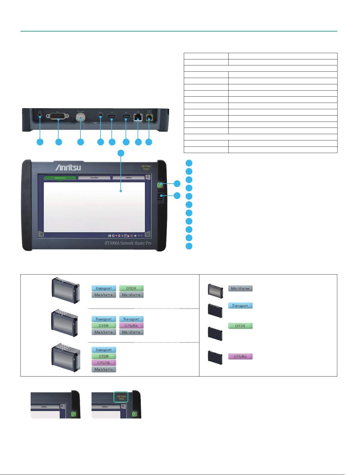
Network Master Pro MT1000A Main Frame
Network Master Pro MT1000A: Main Frame
The Network Master Pro MT1000A is a multiplatform designed for field
testing that is configured using a combination of transport and optical.
The Main Frame controls the test modules which can be changed freely
to any custom configuration matching the users testing requirements.
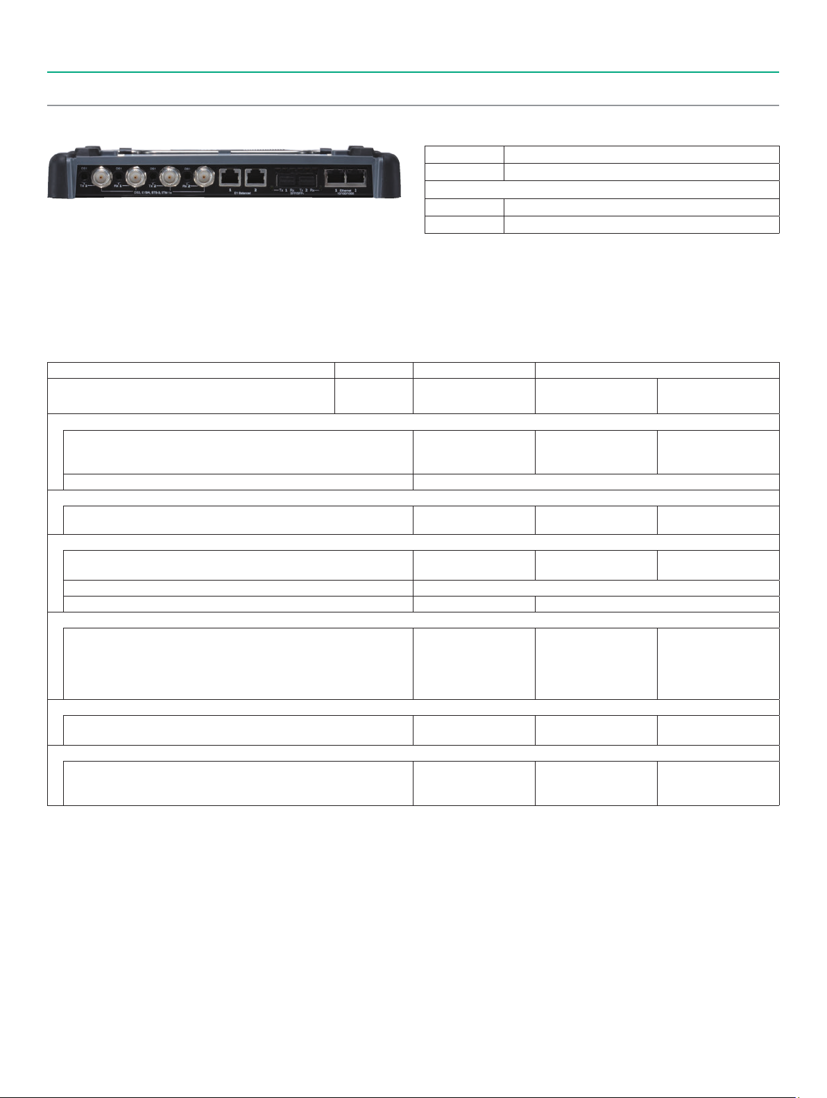
Network Master Pro MT1000A
1 2 73 4 5 6 8
9
No Measurement Module
Model/Order No. Name
MT1000A Network Master Pro
MT1000A-006*
B0745A Softcase: 1 pc
B0728A*
G0385A*
G0310A Li-ion Battery: 1 pc
Z1746A Stylus: 1 pc
Z1747A*
Z1748A*
Z1817A*
MT1000A-003*
MT1000A-005*
1
Audio (3.5ø: CTIA Standard)
2
AUX (D-SUB 15 pin)
3
Clock Input
10
4
USB Mini-B
11
5
USB A
6
USB A
7
Ethernet Service Interface (For remote control)
8
DC Input (18 V DC)
9
9-inch active TFT display and touch screen
10
Power switch
11
Speaker
1
3
4
5
6
7
8
9
Standard Accessories
High Power Supply: Installed
Line Cord*
Rear Panel kit: 1 pc
High Power AC Adaptor: 1 pc
Carrying Strap: 1 pc
Handle: 1 pc
Utilities ROM: 1 pc
Connectivity for WLAN/Bluetooth
AUX I/O
2
: 1 pc
Options
Module Configuration*
1 Module
2 Modules
3 Modules
1: The presence of the MT1000A-006 option can be recognized at the top right
*
of the front panel. To retrofit to the already shipped item, please contact us.
Without MT1000A-006 With in MT1000A-006
2: One line cord is attached to the area to shipment.
*
3: Composed of B0720A, B0729A, B0730A and B0731A (see pages 15 and 23).
*
Refer to Module Composition for the module combination.
4: The MT1000A with MT1000A-006 can be used. Use the AC Adapter G0309A
*
when using the MT1000A without MT1000A-006 installed.
5: Shoulder strap for MT1000A.
*
10
*
11
MT1000A
10G Multirate MU100010A
100G Multirate MU100011A
1310/1550 nm SMF MU100020A
1310/1550/850/1300 nm SMF/MMF MU100021A
1310/1550/1625 nm SMF MU100022A
1310/1550 nm, 1650 nm SMF MU100023A
MU100090A
6: Hand strap for MT1000A.
*
7: This DVD includes PDF files and formatting tools of each product's instruction
*
manual (such as W3933AE, W3810AE, W3736AE, W3946AE).
8: Available for certified countries and regions including USA, Canada, Japan and
*
EU countries. Please visit the Anritsu web site for updated information.
The Bluetooth
Inc.
9: MT1000A-005 is required for MU100090A. To retrofit to the already
*
shipped item, please contact us.
10: Any modular combination as shown in a figure.
*
11: Required if the transport module is not used rear cover.
*
®
mark and logos are registered trademarks of Bluetooth SIG,
Network Master Pro
Transport Module
OTDR Module
High Performance GPS Disciplined Oscillator
3
Page 4
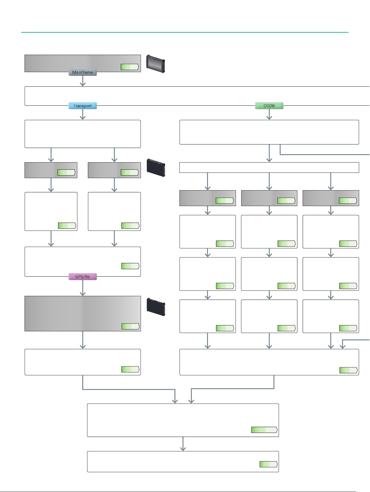
New Purchase Flowchart
Use this flowchart to select options when purchasing a new MT1000A.
MT1000A
Choose the mainframe and mainframe options.
Select testing requirements
Confirming comms quality such as OTN, Ethernet, etc. Checking optical fiber breaks and quality
Page 3
Select the type of interface to measure
(10G) For measuring PDH/DSn interfaces. Ethernet and OTN can
be measured simultaneously using Port 2.
(100G) For measuring 100G/25G Ethernet and OTU4.
One-way delay measurement using two MT1000A units
10G 100G
Choose MU100010A
Page 6
Select Protocol
Select the model for
choosing the measurement
protocol port number,
options, etc., from 1-1-1
Selecting Protocol Options.
Page 6
Select Optical I/F
Select the model for choosing the optical module frequency and bit
rate from 1-3 Selecting Optical Transceiver for Transport Module.
Choose synchronization measurement accuracy
Select the MU100090A when requiring either network Time/phase
measurement described in section 1.4 Selecting High-Accuracy
Oscillator Option, or one-way delay using two MT1000A/
MU100011A units.
Choose MU100011A
Page 7
Select Protocol
Select the model for
choosing the measurement
protocol port number,
options, etc., from 1-2-1
Selecting Protocol Options.
Page 7
Page 8
Page 9
Unit size:
1U/3U
Unit size:
1U/3U
Select Optical Fiber
Select the type of optical fiber to measure
Single Model only
Both Single and Multimode fiber
Single Model only
Wavelength select
2 Wavelength
(1310/1550 nm) (1310/1550/
Choose MU100020A
Page 10
Select Dynamic Range
Select the model with the
required test wavelength and
dynamic range from 2-1-1
Selecting Dynamic Range.
Page 10
Select Connector
Select the model with the
required connector type from
2-1-2 Selecting Polish Type/
Connector Adapter.
Page 10
With/Without Visible Light Source
Select the model with built-in
visible light source if required
from 2-1-3 Selecting Visible
Light Source Option.
Page 10
3 Wavelength
1625 nm)
Choose MU100022A
Select Dynamic Range
Select the model with the
required test wavelength and
dynamic range from 2-3-1
Selecting Dynamic Range.
Select Connector
Select the model with the
required connector type from
2-3-2 Selecting Polish Type/
Connector Adapter.
With/Without Visible Light Source
Select the model with built-in
visible light source if required
from 2-3-3 Selecting Visible
Light Source Option.
Both Single and Multimode fiber
3 Wavelength
(1310/1550/
1650 nm)
Choose MU100023A
Page 12
Select Dynamic Range
Select the model with the
required test wavelength and
dynamic range from 2-4-1
Selecting Dynamic Range.
Page 12
Select Connector
Select the model with the
required connector type from
2-4-2 Selecting Polish Type/
Connector Adapter.
Page 12
With/Without Visible Light Source
Select the model with built-in
visible light source if required
from 2-4-3 Selecting Visible
Light Source Option.
Page 12
Page 13
Page 13
Page 13
Page 13
Select Transport Test Options
Select the model for choosing the required options from 1-5
Selecting Transport Test Option.
Selecting Main Frame Application Parts
Select the main frame application parts from 3-1 MT1000A Selecting Common Application Parts.
Select the model for the extended hardware warranty from 3-2 MT1000A Selecting Extended Warranty Services.
Select the model from 3-3 Remote Software Service.
Record the purchased model and name in the MT1000A configuration confirmation order sheet.
4
Page 9
Selecting OTDR Test Options
Select the models with the option choices from 2-5-1 OTDR Module Conversion Connector Adapters,
2-5-2 Optical Fiber Conversion Adapters, and 2-5-3 Others.
Page 15 to 17
Page 23
Page 14
Page 5
Choose MU100021A
Page 11
Select Dynamic Range
Select the model with the
required test wavelength and
dynamic range from 2-2-1
Selecting Dynamic Range.
Page 11
Select Connector
Select the model with the
required connector type from
2-2-2 Selecting Polish Type/
Connector Adapter.
Page 11
With/Without Visible Light Source
Select the model with built-in
visible light source if required
from 2-2-3 Selecting Visible
Light Source Option.
Page 11
Unit size:
1U/3U
Module Combination Example
MU100011A
MT1000A
MU100010A
MU100021A
MT1000A
MU100011A
MU100021A
MU100090A
MT1000A
5
Page 6
New Purchase
Transport Module
1-1 10G Multirate Module MU100010A
Model Name
MU100010A 10G Multirate Module
Standard Accessories
W3935AE MT1000A Transport Quick Reference Guide: 1 pc
The 10G Multirate Module MU100010A supports communications
network technologies with speeds ranging from 1.5 Mbps to 10 Gbps. It
has the functions and performance required for network I&M tests. In
addition, optional test protocols can be selected and added. This
excellent expandability helps cut initial capital costs and supports
introduction of new functions matching the work schedule.
1-1-1 Selecting Protocol Options
The protocol options are software options for transport technologies supporting each bit rate.
At least one Channel option must be selected from the following list.
MU100010A Bit Rate Less than 5G From 6G to 10G
Transport Technology
Ethernet
IPv4/IPv6, Y.1564, IEEE 1588 v2, RFC 2544, BER, Multistream, OAM, SyncE, MPLS,
MPLS-TP, Multistage VLAN, PBB, Ping/Traceroute, Cable Tests, In-band Control,
Auto discovery, Path-through
TCP Throughput Test (RFC 6349, iPerf) MU100010A-020 TCP Throughput
eCPRI/RoE (IEEE1914.3)
IPv4/IPv6, BER, VLAN, SyncE, IEEE 1588 v2, E-OAM
2, *3
OTN*
Errors/Alarms, Error Performance/Delay/APS Test, FEC Test, O.182 Test,
Overhead Editing/Capture, TCM Monitoring/Generation, Tributary Scan
ODU Multiplexing Addition*
ODU Flex Addition*
CPRI/OBSAI
CPRI/OBSAI L1: Level/Bit Rate/Frequency deviation Measurement,
Alarms/Errors Detection, Unframed BER
CPRI/OBSAI L2: Link Status Monitoring, Alarms/Errors Detection,
Framed BER Measurement, RTD Measurement,
Monitoring using Passthrough
Fibre Channel
Performance Test, Signal Generation/Monitoring, Latency, BER,
Line Alarm/Error Monitoring
SDH/SONET, PDH/DSn
PDH/DSn Test, Tw-Way Monitoring/Mapping, Errors/Alarms,
Error Performance/Delay/APS Test, Header Monitoring/Generation,
Pointer Event Generation, Tributary Scan
1: The channel is not related to the physical port position. The user can freely choose either of the two physical ports assigned to the option via software.
*
For a dual channel setup, the two different ports of one protocol can operate simultaneously, or two different single channel options can operate simultaneously.
2: Please see the datasheet for supported OTN mapping.
*
3: When using the OTN function, the channel can be used as client signal mapped to OTN. For example, when mapping STM-64/OC-192 to OTU2, both the
*
MU100010A-051/052 (for physical port) and the MU100010A-081/082 (for client signal) are required.
4: When the ODU Multimapping option is installed, OTN multistage mapping measurements are supported.
*
This one option supports both single channel and dual channel.
5: When the ODU Flex option is installed, since transport is over OTN networks, mappings based on used ODU Flex standard can be measured.
*
This one option supports both single channel and dual channel.
4
5
No. of
Measurement
1
Ports*
B0692A* ESD Box (for optical modules): 1 pc
: Up to four SFP+/SFPs can be stored.
*
2 (Dual Channel) 1 (Single Channel) 2 (Dual Channel)
MU100010A-001
Up to 2.7G Dual Channel
MU100010A-001
Up to 2.7G Dual Channel
MU100010A-001
Up to 2.7G Dual Channel
— MU100010A-062 ODU Flex
MU100010A-071
CPRI/OBSAI Up to 5G
Dual Channel
MU100010A-002
FC 1G 2G 4G Dual Channel
MU100010A-001
Up to 2.7G Dual Channel
MU100010A-011
Ethernet 10G Single Channel
MU100010A-011
Ethernet 10G Single Channel
MU100010A-051
OTN 10G Single Channel
MU100010A-061 ODU Multiplexing
MU100010A-072
CPRI/OBSAI 6G to 10G
Single Channel
MU100010A-091
FC 8G 10G Single Channel
MU100010A-081
STM-64 OC-192
Single Channel
MU100010A-012
Ethernet 10G Dual Channel
MU100010A-012
Ethernet 10G Dual Channel
MU100010A-052
OTN 10G Dual Channel
MU100010A-073
CPRI/OBSAI 6G to 10G
Dual Channel
MU100010A-092
FC 8G 10G Dual Channel
MU100010A-082
STM-64 OC-192
Dual Channel
6
Page 7
New Purchase
Transport Module
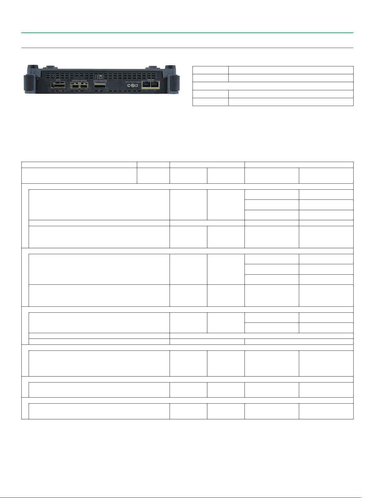
1-2 100G Multirate Module MU100011A
Model Name
MU100011A* 100G Multirate Module
Standard Accessories
W3935AE MT1000A Transport Quick Reference Guide: 1 pc
The 100G Multirate Module MU100011A supports communications
network technologies with speeds ranging from 10 Mbps to 100 Gbps.
It has the functions and performance required for network I&M tests.
In addition, optional test protocols can be selected and added.
This excellent expandability helps cut initial capital costs and supports
introduction of new functions matching the work schedule.
1-2-1 Selecting Protocol Options
The protocol options are software options for transport technologies supporting each bit rate.
At least one Channel option must be selected from the following list.
MU100011A Bit Rate Up to 10G Higher than 10G
Transport Technology
Ethernet
IPv4/IPv6, Y.1564, IEEE 1588 v2, RFC 2544, BER, Multistream, OAM,
SyncE, MPLS, MPLS-TP, Multistage VLAN, PBB, Ping/Traceroute,
Cable Tests, In-band Control, Auto discovery, Path-through
TCP Throughput Test (RFC 6349, iPerf) MU100011A-020
Measurement using 100GBASE-SR — —
eCPRI/RoE (IEEE1914.3)
IPv4/IPv6, BER, VLAN, SyncE, IEEE 1588 v2, E-OAM
Measurement using 100GBASE-SR — —
4, *5
*
OTN
Errors/Alarms, Error Performance/Delay/APS Test, FEC Test,
O.182 Test, Overhead Editing/Capture, TCM Monitoring/
Generation, Tributary Scan
4, *6
ODU Multiplexing Addition
ODU Flex Addition
*
4, *7
*
CPRI/OBSAI
CPRI/OBSAI L1: Level/Bit Rate/Frequency deviation Measurement,
Alarms/Errors Detection, Unframed BER
CPRI/OBSAI L2: Link Status Monitoring, Alarms/Errors Detection,
Framed BER Measurement, RTD Measurement,
Monitoring using Passthrough
Fibre Channel
Performance Test, Signal Generation/Monitoring, Latency, BER,
Line Alarm/Error Monitoring
SDH/SONET
PDH/DSn Test, Tw-Way Monitoring/Mapping, Errors/Alarms,
Error Performance/Delay/APS Test, Header Monitoring/Generation,
Pointer Event Generation, Tributary Scan
1: The channel is not related to the physical port position. The user can freely choose either of the two physical ports assigned to the option via software.
*
For a dual channel setup, the two different ports of one protocol can operate simultaneously, or two different single channel options can operate simultaneously.
2: FEC selectable On/Off.
*
3: Option supports eCPRI/RoE protocol tests only.
*
4: Please see the datasheet for supported OTN mapping.
*
5: When using the OTN function, the channel can be used as client signal mapped to OTN.
*
For example, when mapping STM-256/OC-768 to OTU4, both the MU100011A-055 (for physical port) and the MU100011A-083 (for client signal) are required.
6: When the ODU Multiplexing/Multistage option is installed, OTN multistage mapping measurements are supported.
*
This one option supports both single channel and dual channel.
7: This mapping function is based on the ODUFlex standard for transmissions over OTN networks and supports client signals of any speed.
*
8: The MU100011A has no STM-256/OC-768 PHY interface; it can be used for OTN client signals.
*
No. of
Measurement
1
*
Ports
(Single Channel)2 (Dual Channel)
MU100011A-001
MU100011A-001
MU100011A-001
MU100011A-071
MU100011A-004
MU100011A-001
B0763A** ESD Box (for optical modules): 1 pc
: MT1000A-006 is required for MU100011A.
*
: One CFP4 plus either up to two QSFP28s or up to four SFP/SFP+s can be
**
stored.
1
1
(Single Channel)
2
*
2
*
Up to 10G
Single Channel
Up to 10G
Single Channel
Up to 10G
Single Channel
MU100011A-017
MU100011A-003
Up to 10G
Dual Channel
TCP Throughput — —
MU100011A-003
Up to 10G
Dual Channel
MU100011A-003
Up to 10G
Dual Channel
Ethernet 25G Single Channel
MU100011A-013
Ethernet 40G Single Channel
MU100011A-015
Ethernet 100G Single Channel
MU100011A-023
RS-FEC for 100GBASE-SR4
MU100011A-015
Ethernet 100G Single Channel
MU100011A-017
Ethernet 25G Single Channel
MU100011A-013
Ethernet 40G Single Channel
MU100011A-015
Ethernet 100G Single Channel
MU100011A-023
RS-FEC for 100GBASE-SR4
MU100011A-015
Ethernet 100G Single Channel
MU100011A-053
OTN 40G Single Channel
MU100011A-055
OTN 100G Single Channel
MU100011A-063 ODU Multiplexing/Multi Stage
MU100011A-062 ODU Flex —
CPRI/OBSAI
Up to 10G
Single Channel
Up to 10G FC
Single Channel
Up to 10G
Single Channel
MU100011A-072
CPRI/OBSAI
Up to 10G
Dual Channel
MU100011A-005
Up to 10G FC
Dual Channel
MU100011A-003
Up to 10G
Dual Channel
MU100011A-073
CPRI 12/25G Single Channel
MU100011A-091
FC 16G Single Channel
8
MU100011A-083
STM-256/OC-768
Client Signal
*
(Dual Channel)
MU100011A-075
eCPRI/RoE 25G Dual Channel
MU100011A-074
CPRI 12/25G Dual Channel
2
—
—
—
—
2, *3
*
—
—
—
—
—
—
—
7
Page 8

New Purchase
Transport Module
Table 1 Protocol Configuration Examples
Pattern 1: When using 2.7 Gbps max. SDH/SONET/OTN/Ethernet interface and 10 GigE single channel
Model Name Notes
MU100010A-001 Up to 2.7G Dual Channel
MU100010A-012 Ethernet 10G Dual Channel Measures 1 port of 10 Gbps Ethernet Interface
With 1 channel running at 10 GigE on either physical port testing on the other physical port can be completed using the 2.7 Gbps channel option.
Pattern 2: When using 10 Gbps max. SDH/SONET/OTN/Ethernet interface, 100 GigE single channel and 10G bps max FC/CPRI/OBSAI single channel.
Model Name Notes
MU100011A-003 Up to 10G Dual Channel Measures (Ethernet, OTN, SDH/SONET) signals at 2 ports simultaneously at up to 10 Gbps max.
MU100011A-015 Ethernet 100G Single Channel Measures 1 port of 100 Gbps Ethernet Interface
MU100011A-004 Up to 10G FC Single Channel Measures 1 port of up to 10 Gbps Fibre Channel Interface
MU100011A-071 CPRI/OBSAI Up to 10G Single Channel Measures 1 port of up to 10 Gbps CPRI/OBSAI Interface
Performing a mapping test from 10 Gbps OTN physical interface to any 10 Gbps client signal. And the test a 100 Gbps Ethernet interface.
1-3 Selecting Optical Transceiver for Transport Module
Optical modules supporting the optical standards can be inserted for testing using the MU100010A/MU100011A.
Select the optical module matching the test requirements.
Measures (OTU1, 1 GigE, STM-16/OC-48) signals at 2 ports simultaneously at up to 2.7 Gbps max.
Order No.
MU110010A
MU110011A
G0332A
G0319A
G0320A
G0321A
G0328A
G0322A
G0323A
G0315A
G0316A
G0318A
G0329A
G0356A
G0386A
G0387A
G0388A
G0389A
G0359A
G0334A
G0366A
G0364A
G0365A
G0369A
Model/
Name
100M FX 1310 nm
MM SFP
Up to 2.7G 1310 nm
15 km SFP
Up to 2.7G 1310 nm
40 km SFP
Up to 2.7G
1550 nm 80 km SFP
1G/2G/4G FC
850 nm SFP
1G/2G/4G FC
1310 nm SFP
1G/2G/4G FC
1550 nm SFP
10G LR/LW 1310 nm
SFP+
10G ER/EW 1550 nm
40 km SFP+
10G ZR/ZW 1550 nm
80 km SFP+
10G LR 1310 nm
SFP+
8G FC/10G SR
850 nm SFP+
16GFC SR 850 nm
SFP+
16GFC LR 1310 nm
SFP+
25G SR 850 nm
SFP28
25G LR 1310 nm
SFP28
40G SR4 850 nm
QSFP+
40G LR4 1310 nm
QSFP+
100G SR4 850 nm
QSFP28
100G LR4 1310 nm
QSFP28
100G LR4 Dual Rate
1310 nm QSFP28
100G LR4 Dual Rate
1310 nm CFP4
Form
Factor
SFP
SFP
SFP
SFP
SFP
SFP
SFP
SFP+
SFP+
SFP+
SFP+
SFP+
SFP+
SFP+
SFP28
SFP28
QSFP+
QSFP+
QSFP28
QSFP28
QSFP28
CFP4
100 Meg Ethernet
156 Meg STM-1
614 Meg CPRI
1310 nm,
MM, 2 km
622 Meg STM-4
768 Meg OBSAI
1GFC
1310 nm, SM, 15 km
1310 nm, SM, 40 km
1550 nm, SM, 80 km
1310 nm, SM, 10 km
1550 nm, SM, 40 km
1.23 Gig CPRI
1.25 Gig Ethernet
1.54 Gig OBSAI
850 nm, MM, 0.5 km
1310 nm, SM, 10 km
2GFC
2.46 Gig CPRI
2.488 Gig STM-16
2.67 Gig OTU1
3.07 Gig CPRI OBSAI
4GFC
4.92 Gig CPRI
6.14 Gig CPRI OBSAI
8GFC
850 nm,
MM, 0.3 km
9.83 Gig CPRI
9.95 Gig STM-64
10.1 Gig CPRI
1310 nm, SM, 10 km
1550 nm, SM, 40 km
1550 nm, SM, 80 km
10.3 Gig Ethernet
10GFC
10.7 Gig OTU2
11.05 Gig OTU1e
11.09 Gig OTU2e
11.27 Gig OTU1f
11.3 Gig OTU2f
16GFC
850 nm,
MM,
0.5 km
1310 nm,
SM,
10 km
850 nm,
MM,
0.5 km
1310 nm,
SM,
10 km
25G Ethernet
40G Ethernet
850 nm,
MM, 0.1 km
1310 nm,
SM, 10 km
40G OTN
850 nm,
MM,
0.1 km
1310 nm,
SM,
10 km
1310 nm, SM,
10 km
1310 nm, SM,
10 km
100G Ethernet
100G OTN
8
Page 9
New Purchase
Transport Module
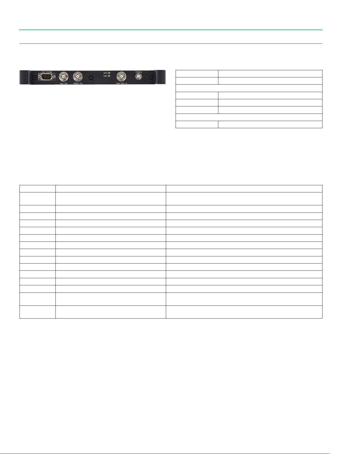
1-4 Choosing High-Accuracy Oscillator Option
High Performance GPS Disciplined Oscillator MU100090A
Model/Order No. Name
1
The MU100090A supplies GPS-synchronized 1 PPS, 10 MHz, and Time
of Day (ToD) signals to the MT1000A as references for measuring the
network and equipment time periodic error and SyncE frequency
deviation using the MU100010A or MU100011A.
MU100090A*
J1705A AUX Conversion Adaptor
J1706A GPS Antenna
J1710A BNC Cable (20 cm) × 2
The measurement target signal is the time stamp in the 1 PPS or IEEE
1588 Ethernet frame. GbE, 10 GbE, and 25 GbE optical interfaces are
supported.
In addition, the one-way delay at the 25G/40G/100G interface between
two distant points can be measured using two MT1000A/MU100011A
MT1000A-005*
1: Excellent Eco Product non-compliant.
*
2: MT1000A-005 is required for MU100090A.
*
units and one MU100090A.
1-5 Selecting Transport Test Option
These options are used in combination with the MU100010A module. Choose options matching the customer’s test requirements. Additionally
today, these options cannot be used in combination with the OTDR Module MU100020A/MU100021A/MU100022A.
Model Name Notes
G0325A GPS Receiver
W3933AE MT1000A Transport Module Operation Manual Printed manual
W3736AE MT1000A/MT1100A Remote Scripting Operation Manual Printed manual
Z1821A Utilities in USB Stick USB memory with operation manual, remote scripts instruction manual, etc.
J1583A Optical Attenuator 10 dB LC/PC to LC/PC
J1584A RJ45 Cable 3 m
J1585A RJ48 to Crocodile Clips Cable 3 m E1 interface cable.
J1586A RJ48 to Crocodile Clips Cable 20 dB ATT 3 m E1 interface cable.
J1588A BNC Cable 2.5 m E1, E3, E4, DS3, STM-1e, STS-3 interface cable. Impedance: 75Ω
J1589A BNC to 1.6/5.6 Cable 2.5 m E1, E3, E4, DS3, STM-1e, STS-3 interface cable. Impedance: 75Ω
J1591A RJ48 to Two 3-pin Banana Plug Cable 2.5 m E1 interface cable.
J1597A RJ48 Balanced PDH Cable Crossed 3 m E1 interface cable.
J1598A Bantam Cable 3 m DS1 interface cable.
J1710A BNC Cable 0.2 m
J0127B COAXIAL CORD, 2.0 M
It is required when measuring one-way latency at Ethernet tests.
However, it is unnecessary when purchasing MU100090A.
BNC cable for MU100090A and main-frame external clock input connector.
Impedance: 50Ω
BNC cable for MU100090A and main-frame external clock input connector.
Impedance: 50Ω
High Performance GPS Disciplined Oscillator
Standard Accessories
Mandatory Main Frame Option
2
AUX I/O
9
Page 10

New Purchase
OTDR Module
2-1 OTDR Module 1310/1550 nm SMF MU100020A
OPM Port SM Port
The OTDR Module 1310/1550 nm SMF MU100020A is an OTDR module
for single mode fiber use only. It supports all-in-one OTDR, FTTA, and
OLTS measurements required for checking optical fiber. Select a model
Model Name
MU100020A OTDR Module 1310/1550 nm SMF
Standard Accessories
J1693A Universal Connector 2.5 mm for OPM: 1 pc
J1694A Universal Connector 1.25 mm for OPM: 1 pc
W3811AE Quick Reference Guide: 1 pc
with the dynamic range matching the test requirements. Additionally,
combined used with the visible light source options support visual
confirmation of fiber breaks, etc.
2-1-1 Selecting Dynamic Range
The MU100020A is available in three models with different dynamic ranges matching the test environment.
Select the One matching the test requirements.
Wavelength: Dynamic Range Model Name
1310/1550 nm: 39/37.5 dB MU100020A-020 Standard Dynamic Range
1310/1550 nm: 42/41 dB MU100020A-021 Enhanced Dynamic Range
1310/1550 nm: 46/46 dB MU100020A-022 High-Performance Dynamic Range
2-1-2 Selecting Polish Type/Connector Adapter
The MU100020A is available in a total of five models (3 UPC and 2 APC) as listed below. Specify the required connector type at ordering.
The specified connector is provided as a standard accessory. The polish type cannot be changed after purchase.
Polish Type
UPC
APC
Connector Adapter
FC Connector
DIN 47256 Connector
SC Connector
2-1-3 Selecting Visible Light Source Option
Model Model
MU100020A-010
MU100020A-037
MU100020A-010
MU100020A-039
MU100020A-010
MU100020A-040
UPC Ultra Physical Contact
MU100020A-011
MU100020A-025
MU100020A-011
MU100020A-026
Breaks in the optical fiber can be detected visually using this light source. This option cannot be added after purchase.
Model Name Notes
MU100020A-002 Visual Fault Locator For direct insertion of 2.5 mm (FC, SC, DIN) optical fiber with fixed diameter of 2.5 mm
J1335A MU/LC Connector Adapter Required conversion adapter for inserting LC (1.25 mm) optical fiber
APC Angled Physical
Contact
10
Page 11

New Purchase
OTDR Module
2-2 OTDR Module 1310/1550/850/1300 nm SMF/MMF MU100021A
MM PortOPM Port SM Port
The OTDR Module 1310/1550/850/1300 nm SMF/MMF MU100021A is
an OTDR module for single and multimode fiber use. It supports all-inone OTDR, FTTA, and OLTS measurements required for checking optical
Model Name
MU100021A OTDR Module 1310/1550/850/1300 nm SMF/MMF
Standard Accessories
J1693A Universal Connector 2.5 mm for OPM: 1 pc
J1694A Universal Connector 1.25 mm for OPM: 1 pc
W3811AE Quick Reference Guide: 1 pc
fiber. Select a model with the dynamic range matching the test
requirements. Additionally, combined used with the visible light source
options support visual confirmation of fiber breaks, etc.
2-2-1 Selecting Dynamic Range
The MU100021A has a fixed dynamic range; select the following model.
Wavelength: Dynamic Range Model Name
1310/1550/850/1300 nm: 42/41/29/28 dB MU100021A-021 Enhanced Dynamic Range
2-2-2 Selecting Polish Type/Connector Adapter
The MU100021A is available in a total of five models (3 UPC and 2 APC) as listed below. Specify the required connector type at ordering.
Two specified connectors (for SMF and MMF ports) are provided as standard accessories. The polish type cannot be changed after purchase.
Connector Adapter
Polish Type
1
UPC*
Model MM Port SM Port Model MM Port SM Port
UPC Ultra
Physical
Contact
UPC Ultra
Physical
Contact
1, *2
APC*
( SM port only,
MM port is UPC)
UPC Ultra
Physical
Contact
APC Angled
Physical
Contact
FC Connector
DIN 47256 Connector
SC Connector
1: Different connector adapter types cannot be specified for the SMF and MMF ports.
*
2: There is no APC polish type for the MMF port. As a result, this connector adapter polish type is UPC.
*
MU100021A-010
MU100021A-037
MU100021A-010
MU100021A-039
MU100021A-010
MU100021A-040
MU100021A-011
MU100021A-025
MU100021A-011
MU100021A-026
2-2-3 Selecting Visible Light Source Option
Breaks in the optical fiber can be detected by eye using this light source. This option cannot be added by retrofit after purchase.
Model Name Notes
MU100021A-002 Visual Fault Locator For direct insertion of 2.5 mm (FC, SC, DIN) optical fiber with fixed diameter of 2.5 mm.
J1335A MU/LC Connector Adapter Required conversion adapter for inserting LC (1.25 mm) optical fiber
11
Page 12

New Purchase
OTDR Module
2-3 OTDR Module 1310/1550/1625 nm SMF MU100022A
OPM Port SM Port
The OTDR Module 1310/1550/1625 nm SMF MU100022A is an OTDR
module for single mode fiber use only. It supports all-in-one OTDR,
FTTA, and OLTS measurements required for checking optical fiber.
Model Name
MU100022A OTDR Module 1310/1550/1625 nm SMF
Standard Accessories
J1693A Universal Connector 2.5 mm for OPM: 1 pc
J1694A Universal Connector 1.25 mm for OPM: 1 pc
W3811AE Quick Reference Guide: 1 pc
Additionally, combined used with the visible light source options
support visual confirmation of fiber breaks, etc.
2-3-1 Selecting Dynamic Range
The MU100022A has a fixed dynamic range; select the following model.
Wavelength: Dynamic Range Model Name
1310/1550/1625 nm: 46/46/44 dB MU100022A-022 High-Performance Dynamic Range
2-3-2 Selecting Polish Type/Connector Adapter
The MU100022A is available in a total of five models (3 UPC and 2 APC) as listed below. Specify the required connector type at ordering.
The specified connector is provided as a standard accessory. The polish type cannot be changed after purchase.
Polish Type
APC
APC Angled Physical
Contact
Connector Adapter
UPC
Model Model
UPC Ultra Physical Contact
FC Connector
DIN 47256 Connector
SC Connector
2-3-3 Selecting Visible Light Source Option
MU100022A-010
MU100022A-037
MU100022A-010
MU100022A-039
MU100022A-010
MU100022A-040
MU100022A-011
MU100022A-025
MU100022A-011
MU100022A-026
Breaks in the optical fiber can be detected visually using this light source. This option cannot be added after purchase.
Model Name Notes
MU100022A-002 Visual Fault Locator For direct insertion of 2.5 mm (FC, SC, DIN) optical fiber with fixed diameter of 2.5 mm
J1335A MU/LC Connector Adapter Required conversion adapter for inserting LC (1.25 mm) optical fiber
12
Page 13

New Purchase
OTDR Module
2-4 OTDR Module 1310/1550 nm, 1650 nm SMF MU100023A
SM Port
OPM Port
(1650 nm)
The OTDR Module 1310/1550 nm, 1650 nm SMF MU100023A is an
OTDR module for single mode fiber use only. It supports all-in-one
OTDR, FTTA, and OLTS measurements required for checking optical
SM Port
(1310/1550 nm)
Model Name
MU100023A OTDR Module 1310/1550/1650 nm SMF
Standard Accessories
J1693A Universal Connector 2.5 mm for OPM: 1 pc
J1694A Universal Connector 1.25 mm for OPM: 1 pc
W3811AE Quick Reference Guide: 1 pc
fiber. Additionally, combined used with the visible light source options
support visual confirmation of fiber breaks, etc.
2-4-1 Selecting Dynamic Range
The MU100023A has a fixed dynamic range; select the following model.
Wavelength: Dynamic Range Model Name
1310/1550 nm: 42/41 dB, 1650 nm: 35 dB MU100023A-021 Enhanced Dynamic Range
2-4-2 Selecting Polish Type/Connector Adapter
The MU100023A is available in a total of five models (3 UPC and 2 APC) as listed below. Specify the required connector type at ordering.
The specified connector is provided as a standard accessory. The polish type cannot be changed after purchase.
Polish Type
APC*
APC Angled Physical
Contact
Connector Adapter
UPC*
Model Model
UPC Ultra Physical Contact
FC Connector
DIN 47256 Connector
SC Connector
: Different types of connector adapters cannot be selected for the SM port (1310/1550 nm) and the SM port (1650 nm).
*
2-4-3 Selecting Visible Light Source Option
MU100023A-010
MU100023A-037
MU100023A-010
MU100023A-039
MU100023A-010
MU100023A-040
MU100023A-011
MU100023A-025
MU100023A-011
MU100023A-026
Breaks in the optical fiber can be detected visually using this light source. This option cannot be added after purchase.
Model Name Notes
MU100023A-002 Visual Fault Locator For direct insertion of 2.5 mm (FC, SC, DIN) optical fiber with fixed diameter of 2.5 mm.
J1335A MU/LC Connector Adapter Required conversion adapter for inserting LC (1.25 mm) optical fiber
13
Page 14

New Purchase
(Physical contact)
OTDR Module
2-5 Selecting MU100020A/MU100021A/MU100022A/MU100023A Options
The OTDR Module connector is available in a total of five types (3 UPC and 2 APC). These connectors can be changed freely by the user. However,
connectors with mismatched polish types cannot be used. In addition, the MU100010A/MU100011A cannot be used.
2-5-1 OTDR Module Conversion Connector Adapters
Model
Name
J0617B (FC/UPC) J0618E (DIN/UPC) J0619B (SC/UPC) J0739A (FC/APC) J1697A (SC/APC)
Changeable Optical
Connector (FC-PC)
Form
2-5-2 Optical Fiber Conversion Adapters
Model Name Notes
J1530A SC Plug-in Converter (UPC (P)-APC (J))
UPC (Option 010), SM/MM Ports APC (Option 011), SM Port
Changeable Optical
Connector (DIN)
Changeable Optical
Connector (SC)
Changeable Optical
Connector (FC-APC)
Changeable Optical
Connector (SC-APC)
SC/UPC → SC/APC Conversion
J1531A SC Plug-in Converter (APC (P)-UPC (J))
J1532A FC Plug-in Converter (UPC (P)-APC (J))
J1533A FC Plug-in Converter (APC (P)-UPC (J))
J1534A LC-SC Plug-in Converter
(for SM, SC (P)-LC (J))
J1535A LC-SC Plug-in Converter
(for MM, SC (P)-LC (J))
(Physical contact)
10° to 25°
(Angle physical contact)
8°
10° to 25°
(Angle physical contact)
8°
(Physical contact)
10° to 25°
UPC (P)
APC (J)
SC/APC → SC/UPC Conversion
APC (P) UPC (J)
FC/UPC → FC/APC Conversion
UPC (P) APC (J)
FC/APC → FC/UPC Conversion
APC (P) UPC (J)
SC/UPC → LC/UPC Conversion.
SM Fiber Only
UPC (P) UPC (J)
SC/UPC → LC/UPC Conversion.
MM Fiber Only
(Angle physical contact)
8°
(Physical contact)
10° to 25°
(Angle physical contact)
8°
(Physical contact)
10° to 25°
(Physical contact)
10° to 25°
2-5-3 Others
14
(Physical contact)
10° to 25°
UPC (J) UPC (P)
(Physical contact)
10° to 25°
Model Name Notes
NETWORKS PC Emulation Software for Data Analysis and Reporting Supports PC running Microsoft Windows 7 and Windows 10 to edit waveform data and
create reports
W3810AE MT1000A MU100020A Network Master Pro Operation Manual MT1000A and MU100020A/MU100021A/MU100022A/MU100023A operation manuals
Page 15

New Purchase
Common Application Parts, Extended Warranty Services and Remote Software Service
3-1 MT1000A Selecting Common Application Parts
Various application parts make the MT1000A more convenient to use.
Softcase B0745A (Standard Accessory)
This bag with shoulder strap can hold the
MT1000A with up to three installed modules.
Hard Case B0691B
This strong plastic case can hold the MT1000A
with up to two installed modules.
462 (W) × 372 (H) × 207 (D) mm
Battery Charger G0324A
This is the charger for the MT1000A G0310A
Li-ion battery.
GPIB–USB Converter J1667A
Converter connected to MT1000A USB interface
for controlling MT1000A over GPIB using
commands from external PC controller.
Video Inspection Probe G0382A/G0306B
Scratches and dirt on the connector end face are a major cause of
degraded communications quality.
The MT1000A has a built-in VIP function for analyzing the condition of
the optical connector end face in the utility menu. When the VIP is
connected, scratches and dirt on the optical connector end face are
visualized (× 400) and the OK/NG status is evaluated based on the
IEC61300-3-35 standard.
Anritsu supports VIP Series G0382A (USB Autofocus Type) and G0306B
(USB Standard Type).
Different tip types are used by the G0382A and G0306B.
G0306BG0382A
AC Adapter G0309A
This AC adapter is used with the MT1000A without MT1000A-006.
It cannot be used with the MT1000A with MT1000A-006 installed.
Car 12 Vdc Adapter J1569B
This adapter supplies power to the MT1000A from an automobile 12-V
cigarette lighter plug.
Use the accessory attachment supplied with the MT1000A main unit
with MT1000A-006 installed.
Optical Cables
Model Name Notes
J1571A Optical cable SM LC/PC to SC/PC 3 m Single core (no paired cables)
J1575A Optical Cable SM LC/PC to FC/PC 3 m Single core (no paired cables)
J1579A Optical Cable SM LC/PC to LC/PC 3 m Single core (no paired cables)
J1581A Optical Cable MM LC/PC to LC/PC 3 m Single core (no paired cables)
MT1000A Module Connection Parts
Model Name Notes
B0720A Rear Panel MT1000A Rear Panel
B0728A Rear Panel Kit Rear Panel (B0720A) and Screw kit (B0732A) (Same as standard accessory)
B0729A Screw 1U 1 unit screw set (Total 4 pcs)
B0730A Screw 2U 2 units screw set (Total 4 pcs)
B0731A Screw 3U 3 units screw set (Total 4 pcs)
B0732A Screw Kit 1U, 2U, 3U screw (Total 12 pcs)
Optical Connector End-face Inspection/Evaluation Screen
15
Page 16

New Purchase
Common Application Parts, Extended Warranty Services and Remote Software Service
3-2 MT1000A Selecting Extended Warranty Services
The standard warranty period is 1 year. An extended warranty can be purchased for the main frame and the test interface modules as listed below.
Model Name
MT1000A
MT1000A-ES210 2 Years Extended Warranty Service (standard 1 year + 1 year)
MT1000A-ES310 3 Years Extended Warranty Service (standard 1 year + 2 years)
MT1000A-ES510 5 Years Extended Warranty Service (standard 1 year + 4 years)
MU100010A
MU100010A-ES210 2 Years Extended Warranty Service (standard 1 year + 1 year)
MU100010A-ES310 3 Years Extended Warranty Service (standard 1 year + 2 years)
MU100010A-ES510 5 Years Extended Warranty Service (standard 1 year + 4 years)
MU100011A
MU100011A-ES210 2 Years Extended Warranty Service (standard 1 year + 1 year)
MU100011A-ES310 3 Years Extended Warranty Service (standard 1 year + 2 years)
MU100011A-ES510 5 Years Extended Warranty Service (standard 1 year + 4 years)
MU100090A
MU100090A-ES210 2 Years Extended Warranty Service (standard 1 year + 1 year)
MU100090A-ES310 3 Years Extended Warranty Service (standard 1 year + 2 years)
MU100090A-ES510 5 Years Extended Warranty Service (standard 1 year + 4 years)
Model Name
MU100020A
MU100020A-ES210 2 Years Extended Warranty Service (standard 1 year + 1 year)
MU100020A-ES310 3 Years Extended Warranty Service (standard 1 year + 2 years)
MU100020A-ES510 5 Years Extended Warranty Service (standard 1 year + 4 years)
MU100021A
MU100021A-ES210 2 Years Extended Warranty Service (standard 1 year + 1 year)
MU100021A-ES310 3 Years Extended Warranty Service (standard 1 year + 2 years)
MU100021A-ES510 5 Years Extended Warranty Service (standard 1 year + 4 years)
MU100022A
MU100022A-ES210 2 Years Extended Warranty Service (standard 1 year + 1 year)
MU100022A-ES310 3 Years Extended Warranty Service (standard 1 year + 2 years)
MU100022A-ES510 5 Years Extended Warranty Service (standard 1 year + 4 years)
MU100023A
MU100023A-ES210 2 Years Extended Warranty Service (standard 1 year + 1 year)
MU100023A-ES310 3 Years Extended Warranty Service (standard 1 year + 2 years)
MU100023A-ES510 5 Years Extended Warranty Service (standard 1 year + 4 years)
16
Page 17

New Purchase
Common Application Parts, Extended Warranty Services and Remote Software Service
3-3 Remote Software Service
The following licenses must be purchased to use the MX109020A Site Over Remote Access.
Mainframe Option License
Model/Order No. Name
MT1000A-003*
MT1000A-011*
1: Available for certified countries and regions including USA, Canada, Japan and EU countries. Please visit the Anritsu web site for updated information.
*
The Bluetooth
2: Validity period is unlimited. An open TCP port may be required to allow the MT1000A to be connected from an in-company LAN to MX109020A, depending on the
*
LAN security policy.
1
2
®
Subscription Option License
Model/Order No. Name
MX109020A*
MX109020A-TL001*
MX109020A-001*
MX109020A-002*
MX109020A-003*
3: We recommend purchasing a 1-year license in addition to the basic license.
*
4: When extending the usage period, we recommend purchasing in 1-year license periods
*
5: Up to two measuring instruments can be remotely controlled simultaneously with the basic license.
*
This number can be increased to up to 8 units by purchasing the MX109020A-001 option, and up to 100 units by purchasing the MX109020A-002 option.
6: You must agree to the service terms before purchasing SORA.
*
Refer to the service terms at the following URL: https://www.anritsu.com/en-AU/test-measurement/support/downloads/manuals/dwl20059
7: This product cannot be used in some regions and countries; please read the service terms for more details.
*
8: Users must provide their own storage at the upload destination.
*
3, *5, *6, *7
WLAN/Bluetooth Connect
Site Over Remote Access Connect
mark and logos are registered trademarks of Bluetooth SIG, Inc.
Site Over Remote Access Basic License
3, *4
Site Over Remote Access 1 Year License
5
Site Over Remote Access 8 Units
5
Site Over Remote Access Unlimited Units
8
Centralized Data Management
17
Page 18

Additional Purchases Flowchart
Use this flowchart when adding modules and options to a previously purchased MT1000A.
Adding Functions
Adding Protocol Options Adding Transport Module Adding Network Time/Phase synchronization test
Confirm the serial numbers of the
MU100010A and MU100011A.
Select Protocol
Select the model for choosing the
measurement protocol port
number, options, etc., from 4-1
Adding Test Protocols for
Transport Module.
Page 20
Select Optical I/F
Select the model for choosing the
optical module frequency and bit
rate from 1-3 Selecting Optical
Transceiver for Transport Module.
Page 8
Select the type of interface to measure
(10G) For measuring PDH/DSn interfaces. Ethernet and OTN can be measured
simultaneously using Port 2.
(100G) For measuring 100G/25G Ethernet and OTU4.
One-way delay measurement using two MT1000A units.
10G 100G
Confirm "High Power Supply" at the front of
the main unit, upper right
Yes
Please contact us.
Choose MU100010A
Page 6
Select Protocol
Select the model for choosing the
measurement protocol port number,
options, etc., from 1-1-1 Selecting
Protocol Options.
Select Optical I/F
Select the model for choosing the optical module frequency and bit rate from 1-3 Selecting
Optical Transceiver for Transport Module.
Page 6
Choose MU100011A
Select Protocol
Select the model for choosing the
measurement protocol port number, options,
etc., from 1-2-1 Selecting Protocol Options.
Page 3
No
Page 7
Page 7
Page 8
Check for MT1000A-005 at the
system information of the main
body.
Yes
Choose MU100090A
Choose synchronization
measurement accuracy
Choose model described in 4-4
Adding Network Time/Phase
Synchronization Test.
No
Please contact us.
Page 22
Page 22
Choose option for data
communications
Choose required options and
models from 4-2 Adding Main
Frame Options for Transport
Function.
Page 22
Choose synchronization measurement accuracy
If network phase measurement required, choose model described in 1-4 Choosing HighAccuracy Oscillator Option.
Page 9
Choose option for data communications
Choose required options and models from 4-2 Adding Main Frame Options for Transport
Function.
Extended Hardware Warranty
Select the model for the extended hardware warranty from 3-2 MT1000A Selecting
Extended Warranty Services.
Selecting Main Frame Application Parts
Select the main frame application parts from 3-1 MT1000A Selecting Common Application
Parts.
In addition, a screw for the number of sheets of the module is necessary separately.
Record the purchased model and name in the configuration confirmation order sheet.
Page 22
Page 17
Page 16
Page 23
18
Page 19

Adding OTDR Module
Select Optical Fiber
Select the type of optical fiber to measure
Single Mode only
Both Single Mode and Multimode
Single Mode only
Wavelength select
2 Wavelength 3 Wavelength 3 Wavelength
(1310/1550 nm) (1310/1550/
Choose MU100020A
Page 10
1625 nm)
Choose MU100022A
Page 12
Both Single Mode and Multimode
(1310/1550/
1650 nm)
Choose MU100023A
Page 13
Choose MU100021A
Page 11
Select Dynamic Range
Select the model with the
required test wavelength and
dynamic range from 2-1-1
Selecting Dynamic Range.
Page 10
Select Connector
Select the model with the
required connector type from
2-1-2 Selecting Polish Type/
Connector Adapter.
Page 10
With/Without Visible Light Source
Select the model with built-in
visible light source if required
from 2-1-3 Selecting Visible
Light Source Option.
Page 10
Selecting OTDR Test Options
Select the models with the option choices from 2-5-1 OTDR Module Conversion Connector Adapters, 2-5-2 Optical Fiber Conversion Adapters, and
2-5-3 Others.
Select Dynamic Range
Select the model with the
required test wavelength and
dynamic range from 2-3-1
Selecting Dynamic Range.
Page 12
Select Connector
Select the model with the
required connector type from
2-3-2 Selecting Polish Type/
Connector Adapter.
Page 12
With/Without Visible Light Source
Select the model with built-in
visible light source if required
from 2-3-3 Selecting Visible
Light Source Option.
Page 12
Select Dynamic Range
Select the model with the
required test wavelength and
dynamic range from 2-4-1
Selecting Dynamic Range.
Page 13
Select Connector
Select the model with the
required connector type from
2-4-2 Selecting Polish Type/
Connector Adapter.
Page 13
With/Without Visible Light Source
Select the model with built-in
visible light source if required
from 2-4-3 Selecting Visible
Light Source Option.
Page 13
Select Dynamic Range
Select the model with the
required test wavelength and
dynamic range from 2-2-1
Selecting Dynamic Range.
Page 11
Select Connector
Select the model with the
required connector type from
2-2-2 Selecting Polish Type/
Connector Adapter.
Page 11
With/Without Visible Light Source
Select the model with built-in
visible light source if required
from 2-2-3 Selecting Visible
Light Source Option.
Page 11
Page 14
19
Page 20

Additional Purchases
Adding New Options to Previously Purchased MT1000A
Confirm the serial numbers of the MT1000A and MU100010A/MU100011A.
4-1 Adding Test Protocols for Transport Module
When adding protocol options later, specify one of the following media types as well as the option.
Model Name
Z1849A DVD-ROM for Retrofit Options
Z1850A USB Stick for Retrofit Options
In addition, when purchasing multiple retrofit options at one time, they are all installed using the same media.
<MU100010A>
To add a new protocol option to a previously purchased MU100010A, choose the required option from the following list.
The MU100010A serial number is required to make the purchase.
Adding MU100010A Protocol Option Bit Rate Less than 5G From 6G to 10G
Transport Technology
Ethernet
IPv4/IPv6, Y.1564, IEEE 1588 v2, RFC 2544, BER, Multistream, OAM, SyncE, MPLS,
MPLS-TP, Multistage VLAN, PBB, Ping/Traceroute, Cable Tests, In-band Control,
Auto discovery, Path-through
TCP Throughput Test (RFC 6349, iPerf) MU100010A-320 TCP Throughput Retrofit
eCPRI/RoE (IEEE1914.3)
IPv4/IPv6, BER, VLAN, SyncE, IEEE 1588 v2, E-OAM
2,
OTN*
Errors/Alarms, Error Performance/Delay/APS Test, FEC Test, O.182 Test,
Overhead Editing/Capture, TCM Monitoring/Generation, Tributary Scan
ODU Multiplexing Addition*
ODU Flex Addition*
3
4
CPRI/OBSAI
CPRI/OBSAI L1: Level/Bit Rate/Frequency deviation Measurement,
Alarms/Errors Detection, Unframed BER
CPRI/OBSAI L2: Link Status Monitoring, Alarms/Errors Detection,
Framed BER Measurement, RTD Measurement,
Monitoring using Passthrough
Fibre Channel
Performance Test, Signal Generation/Monitoring, Latency, BER,
Line Alarm/Error Monitoring
SDH/SONET, PDH/DSn
PDH/DSn Test, Tw-Way Monitoring/Mapping, Errors/Alarms,
Error Performance/Delay/APS Test, Header Monitoring/Generation,
Pointer Event Generation, Tributary Scan
1: The channel is not related to the physical port position. The user can freely choose either of the two physical ports assigned to the option via software.
*
For a dual channel setup, the two different ports of one protocol can operate simultaneously, or two different single channel options can operate simultaneously.
2: When using the OTN function, the channel can be used as client signal mapped to OTN. For example, when mapping STM-64/OC-192 to OTU2, both the
*
MU100010A-351/352 (for physical port) and the MU100010A-381/382 (for client signal) are required.
3: When the ODU Multimapping option is installed, OTN multistage mapping measurements are supported.
*
This one option supports both single channel and dual channel.
4: When the ODU Flex option is installed, since transport is over OTN networks, mappings based on used ODU Flex standard can be measured.
*
This one option supports both single channel and dual channel.
No. of
Measurement
1
Ports*
2 (Dual Channel) 1 (Single Channel) 2 (Dual Channel)
MU100010A-301
Up to 2.7G Dual Channel
Retrofit
MU100010A-301
Up to 2.7G Dual Channel
Retrofit
MU100010A-301
Up to 2.7G Dual Channel
Retrofit
MU100010A-311
Ethernet 10G Single Channel
Retrofit
MU100010A-311
Ethernet 10G Single Channel
Retrofit
MU100010A-351
OTN 10G Single Channel
Retrofit
MU100010A-312
Ethernet 10G Dual Channel
MU100010A-312
Ethernet 10G Dual Channel
MU100010A-352
OTN 10G Dual Channel
MU100010A-361 ODU Multiplexing Retrofit
— MU100010A-362 ODU Flex Retrofit
MU100010A-371
CPRI/OBSAI Up to 5G
Dual Channel Retrofit
MU100010A-302
FC 1G 2G 4G Dual Channel
Retrofit
MU100010A-301
Up to 2.7G Dual Channel
Retrofit
MU100010A-372
CPRI/OBSAI 6G to 10G
Single Channel Retrofit
MU100010A-391
FC 8G 10G Single Channel
Retrofit
MU100010A-381
STM-64 OC-192
Single Channel Retrofit
MU100010A-373
CPRI/OBSAI 6G to 10G
Dual Channel Retrofit
MU100010A-392
FC 8G 10G Dual Channel
MU100010A-382
STM-64 OC-192
Dual Channel Retrofit
Retrofit
Retrofit
Retrofit
Retrofit
20
Page 21

Additional Purchases
Adding New Options to Previously Purchased MT1000A
<MU100011A>
To add a new protocol option to a previously purchased MU100011A, choose the required option from the following list.
The MU100011A serial number is required to make the purchase.
Adding MU100010A Protocol Option Bit Rate Up to 10G Higher than 10G
Transport Technology
Ethernet
IPv4/IPv6, Y.1564, IEEE 1588 v2, RFC 2544, BER, Multistream, OAM,
SyncE, MPLS, MPLS-TP, Multistage VLAN, PBB, Ping/Traceroute,
Cable Tests, In-band Control, Auto discovery, Path-through
TCP Throughput Test (RFC 6349, iPerf) MU100011A-320
Measurement using 100GBASE-SR — —
eCPRI/RoE (IEEE1914.3)
IPv4/IPv6, BER, VLAN, SyncE, IEEE 1588 v2, E-OAM
Measurement using 100GBASE-SR — —
2, *3
*
OTN
Errors/Alarms, Error Performance/Delay/APS Test, FEC Test,
O.182 Test, Overhead Editing/Capture, TCM Monitoring/Generation,
Tributary Scan
2, *4
ODU Multiplexing Addition
ODU Flex Addition
*
2, *5
*
CPRI/OBSAI
CPRI/OBSAI L1: Level/Bit Rate/Frequency deviation Measurement,
Alarms/Errors Detection, Unframed BER
CPRI/OBSAI L2: Link Status Monitoring, Alarms/Errors Detection,
Framed BER Measurement, RTD Measurement,
Monitoring using Passthrough
Fibre Channel
Performance Test, Signal Generation/Monitoring, Latency, BER,
Line Alarm/Error Monitoring
SDH/SONET
PDH/DSn Test, Tw-Way Monitoring/Mapping, Errors/Alarms,
Error Performance/Delay/APS Test, Header Monitoring/Generation,
Pointer Event Generation, Tributary Scan
1: The channel is not related to the physical port position. The user can freely choose either of the two physical ports assigned to the option via software.
*
For a dual channel setup, the two different ports of one protocol can operate simultaneously, or two different single channel options can operate simultaneously.
2: Please see the datasheet for supported OTN mapping.
*
3: When using the OTN function, the channel can be used as client signal mapped to OTN.
*
For example, when mapping STM-256/OC-768 to OTU4, both the MU100011A-355 (for physical port) and the MU100011A-383 (for client signal) are required.
4: When the ODU Multiplexing/Multistage option is installed, OTN multistage mapping measurements are supported.
*
This one option supports both single channel and dual channel.
5: This mapping function is based on the ODUFlex standard for transmissions over OTN networks and supports client signals of any speed.
*
6: The MU100011A has no STM-256/OC-768 PHY interface; it can be used for OTN client signals.
*
7: Option supports eCPRI/RoE protocol tests only.
*
8: FEC can be switched ON/OFF.
*
9: FEC is always OFF.
*
No. of
Measurement
1
*
Ports
1 (Single Channel) 2 (Dual Channel) 1 (Single Channel) 2 (Dual Channel)
8
*
9
*
9
*
8
*
9
*
8
*
MU100011A-375
eCPRI/RoE 25G Dual
9
*
9
*
8
*
9
*
MU100011A-301
Up to 10G
Single Channel Retrofit
MU100011A-301
Up to 10G
Single Channel Retrofit
MU100011A-301
Up to 10G
Single Channel Retrofit
MU100011A-317
Ethernet 25G
MU100011A-303
Up to 10G
Dual Channel Retrofit
TCP Throughput — —
MU100011A-303
Up to 10G
Dual Channel Retrofit
MU100011A-303
Up to 10G
Dual Channel Retrofit
Single Channel Retrofit
MU100011A-313
Ethernet 40G
Single Channel Retrofit
MU100011A-315
Ethernet 100G
Single Channel Retrofit
MU100011A-323
RS-FEC for 100GBASE-SR4
Retrofit
MU100011A-315
Ethernet 100G
Single Channel Retrofit
MU100011A-317
Ethernet 25G
Single Channel Retrofit
MU100011A-313
Ethernet 40G
Single Channel Retrofit
MU100011A-315
Ethernet 100G
Single Channel Retrofit
MU100011A-323
RS-FEC for 100GBASE-SR4
Retrofit
MU100011A-315
Ethernet 100G
Single Channel Retrofit
MU100011A-353
OTN 40G
Single Channel Retrofit
MU100011A-355
OTN 100G
Single Channel Retrofit
MU100011A-363 ODU Multiplexing/Multi Stage Retrofit
MU100011A-362 ODU Flex Retrofit —
MU100011A-371
CPRI/OBSAI Up to 10G
Single Channel Retrofit
MU100011A-304
Up to 10G FC
Single Channel Retrofit
MU100011A-301
Up to 10G
Single Channel Retrofit
MU100011A-372
CPRI/OBSAI Up to 10G
Dual Channel Retrofit
MU100011A-305
Up to 10G FC
Dual Channel Retrofit
MU100011A-303
Up to 10G
Dual Channel Retrofit
MU100011A-373
CPRI 12/25G
Single Channel Retrofit
MU100011A-391
FC 16G
Single Channel Retrofit
MU100011A-383
STM-256/OC-768
Client Signal Retrofit
MU100011A-374
Dual Channel Retrofit
6
*
—
—
—
—
Channel Retrofit
—
—
—
—
—
CPRI 12/25G
—
—
7, *8
*
21
Page 22

Additional Purchases
Adding New Options to Previously Purchased MT1000A
4-2 Adding Main Frame Options for Transport Function
The MT1000A serial number is required at purchase.
Model Name Notes
MT1000A-303 Connectivity for WLAN/Bluetooth Retrofit WLAN/Bluetooth options (can be used in approved countries, including N. America, Japan, EU;
see Anritsu web site for latest list of countries)
When adding protocol options later, specify one of the following media types as well as the option.
Model Name
Z1849A DVD-ROM for Retrofit Options
Z1850A USB Stick for Retrofit Options
1
MT1000A-311*
1: This option enables remote control of the MT1000A using the Site Over Remote Access MX109020A software. We recommend using in conjunction with the WLAN/
*
Bluetooth option MT1000A-003/303. A Wi-Fi dongle can be used in countries and regions where WLAN is not supported.
For a list of supported Wi-Fi dongles, please contact us.
4-3 Adding Transport Module
When adding the MU100010A to a previously purchased MT1000A, use the same procedure as for 10G Multirate Module MU100010A described on
pages 6 thru 8, 16 and 17.
Site Over Remote Access Connect Retrofit
4-4 Adding Network Time/Phase Synchronization Test
Purchase the following products when adding the Network Time/Phase synchronization test and measuring using two synchronized MT1000A units.
High Performance GPS Disciplined Oscillator MU100090A
Model/Order No. Name
MU100090A High Performance GPS Disciplined Oscillator
Standard Accessories
J1705A AUX Conversion Adaptor
J1706A GPS Antenna
J1710A BNC Cable (20 cm) × 2
Main Frame Option
2
MT1000A-005*
2: The MT1000A-005 is mandatory option for use of MU100090A. Confirm if all of MT1000As which you install the MU100090A have MT1000A-005 or not.
*
If they does not have it please contact us.
AUX Interface
Model/Order No. Name
Extended Warranty Service
MU100090A-ES210
MU100090A-ES310
MU100090A-ES510
2 Years Extended Warranty Service
(standard 1 year + 1 year)
3 Years Extended Warranty Service
(standard 1 year + 2 years)
5 Years Extended Warranty Service
(standard 1 year + 4 years)
4-5 Adding OTDR Module
When adding the OTDR Module to a previously purchased MT1000A, use the same procedure as for OTDR Module described on pages 10 thru 17.
4-6 Adding MX109020A Option
Requires MX109020A serial number at purchase.
Model Name Notes
MX109020A-TL001 Site Over Remote Access 1 Year License Extends MX109020A usage period by 1 year
MX109020A-301 Site Over Remote Access 8 Units Extends number of instruments simultaneously controlled by MX109020A to 8 units
MX109020A-302 Site Over Remote Access Unlimited Units Extends number of instruments simultaneously controlled by MX109020A to 100 units
MX109020A-303 Centralized Data Management Supports upload of measurement report from MT1000A to cloud storage
22
Page 23

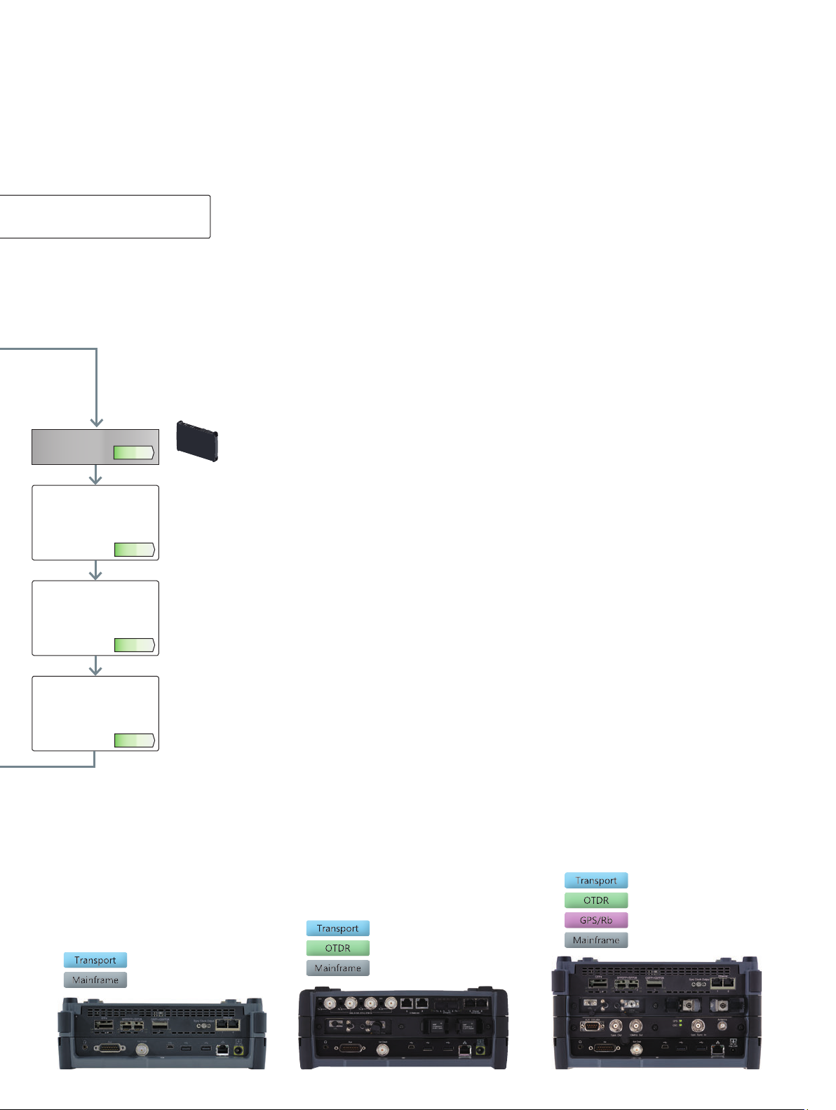
Network Master Pro MT1000A
Configuration Examples
By combining multiple modules, MT1000A can be used as a measuring instrument suitable for the field.
There will introduce a configuration example tailored to the exam situation.
I&M for Core/Metro Network
Optical fiber check and 100G transport testing
Model Name
MT1000A Network Master Pro
MU100011A 100G Multirate Module
MU100011A-015 Ethernet 100G Single channel
MU100011A-055 OTN 100G Single Channel
G0365A 100G LR4 Dual Rate 1310 nm QSFP28
MU100022A OTDR Module 1310/1550/1625 nm SMF
MU100022A-022 High-Performance Dynamic Range
MU100022A-010 UPC Polish
MU100022A-037 FC Connector
MU100022A-002 Visual Fault Locator
I&M for Mobile Backhaul
Evaluate SyncE and IEEE 1588 v2 (PTP), and evaluate the time
synchronization accuracy of the network.
Model Name
MT1000A Network Master Pro
MT1000A-005 AUX I/O
MU100010A 10G Multirate Module
MU100010A-001 Up to 2.7G Dual Channel
MU100010A-012 Ethernet 10G Dual Channel
G0315A 10G LR/LW 1310 nm SFP+
MU100090A High Performance GPS Disciplined Oscillator
I&M for Data Center
Confirm the data quality inside the station building and the
communication quality with the IX.
Model Name
MT1000A Network Master Pro
MU100011A 100G Multirate Module
MU100011A-001 Up to 10G Dual Channel
MU100011A-017 Ethernet 25G Single Channel
MU100011A-020 TCP Throughput
MU100011A-005 Up to 10G FC Dual Channel
MU100011A-091 FC 16G Single Channel
G0329A 10G LR 1310 nm SFP+
G0356A 8G FC/10G FC SR 850 nm SFP+
G0386A 16GFC SR 850 nm SFP+
G0388A 25G SR 850 nm QSFP+
G0389A 25G LR 1310 nm QSFP+
I&M for Mobile Fronthaul
Evaluate breakage of optical fiber and transmission quality of Ethernet
and CPRI/OBSAI.
Model Name
MT1000A Network Master Pro
MU100010A 10G Multirate Module
MU100010A-071 CPRI/OBSAI Up to 5G Dual Channel
MU100010A-073 CPRI/OBSAI 6G to 10G Dual Channel
G0319A Up to 2.7G 1310 nm 15 km SFP
G0329A 10G LR 1310 nm SFP+
MU100021A OTDR Module 1310/1550 nm SMF
MU100021A-021 Standard Dynamic Range
MU100021A-010 UPC Polish
MU100021A-040 SC Connector
MU100021A-002 Visual Fault Locator
J1534A LC-SC Plug-in Converter (SC (P)-LC (J) for SM fiber)
J1535A LC-SC Plug-in Converter (SC (P)-LC (J) for MM fiber)
68-10-R SFP (Optical Module), 3.7 Gbps SFP, 850 nm
68-6-R SFP+ (Optical Module), 8G FC/10G SFP, 1310 nm
Check of Dark Fiber
It will evaluate the disconnection of the dark fiber to be used for the
first time and the optical signal quality.
Model Name
MT1000A Network Master Pro
MU100022A OTDR Module 1310/1550/1625 nm SMF
MU100022A-022 High-Performance Dynamic Range
MU100022A-010 UPC Polish
MU100022A-037 FC Connector
MU100022A-002 Visual Fault Locator
Order Sheet
When recording different MT1000A configurations on one order sheet, describe each MT1000A configuration on one line with the accompanying
options under the relevant line.
Model Name Quantity
23
Page 24

Network Master Pro MT1000A
Procedure for Attaching Some Measurement Modules
MT1000A measurement modules can be removed and changed.
Module Configuration
1 Module
MT1000A
Network Master Pro
2 Modules
3 Modules
This explains the method and precautions.
Step 1: Version up the software for MT1000A
Install the latest software in the MT1000A. This software can be
obtained from the Anritsu web site.
There are two MT1000A installers; download the installer matching the
*
measurement module to be used.
Step 2: Remove the battery pack from Mainframe
1) Disconnect the AC cable.
2) Use screw driver or Coin and remove the battery lid from MT1000A.
10G Multirate MU100010A
100G Multirate MU100011A
1310/1550 nm SMF MU100020A
1310/1550/850/1300 nm SMF/MMF MU100021A
1310/1550/1625 nm SMF MU100022A
1310/1550 nm, 1650 nm SMF MU100023A
MU100090A
Transport Module
OTDR Module
High Performance GPS Disciplined Oscillator
Step 3: Replacing the connected modules
1) Place the instrument on its front on a plain surface.
Loosen the screws (shown by the blue circle) on rear side of the
connected module.
3) Remove the battery pack.
24
2) After loosing the four screws, lift up the connected module with
holding both sides.
If you cannot lift up, loosen the four screws again.
You can see the panel as below.
Page 25

Network Master Pro MT1000A
Procedure for Attaching Some Measurement Modules
Step 4: Attaching the new module and the former module
1) Remove four screws of former module and replace to the next screws. Please arrange a screw separately.
2) Attach the former module to the new module. Please check modular turn, referring to 3 pages. Place the former module on the new modules as
to connect following pairs: Align the four corners when installing the module.
At this time, take care not to let connectors 2 and 4 come into contact with guide pins 1, 3, 5, and 6. Doing so may damage the module connectors.
1 2
For 3 modules (B0731A)
For 2 modules (B0730A)
For 1 module (B0729A)
4 5
3
6
MT1000A Main Frame Side Measurement Module Side
3) Tighten the four screws.
After the module attachment has finished, the external appearance will be as below.
Step 5: After attaching the modules
1) After attaching the modules, connect the AC cable or install the battery packs.
2) Turn on the MT1000A. Please check whether a new module is recognized at the system information
25
Page 26

Note
26
Page 27

Note
27
Page 28

•
United States
Anritsu Americas Sales Company
450 Century Parkway, Suite 190, Allen, TX 75013 U.S.A.
Phone: +1-800-Anritsu (1-800-267-4878)
•
Canada
Anritsu Electronics Ltd.
700 Silver Seven Road, Suite 120, Kanata,
Ontario K2V 1C3, Canada
Phone: +1-613-591-2003
Fax: +1-613-591-1006
•
Brazil
Anritsu Eletronica Ltda.
Praça Amadeu Amaral, 27 - 1 Andar
01327-010 - Bela Vista - Sao Paulo - SP, Brazil
Phone: +55-11-3283-2511
Fax: +55-11-3288-6940
•
Mexico
Anritsu Company, S.A. de C.V.
Blvd Miguel de Cervantes Saavedra #169 Piso 1, Col. Granada
Mexico, Ciudad de Mexico, 11520, MEXICO
Phone: +52-55-4169-7104
•
United Kingdom
Anritsu EMEA Ltd.
200 Capability Green, Luton, Bedfordshire, LU1 3LU, U.K.
Phone: +44-1582-433200
Fax: +44-1582-731303
•
France
Anritsu S.A.
12 avenue du Québec, Immeuble Goyave,
91140 VILLEBON SUR YVETTE, France
Phone: +33-1-60-92-15-50
•
Germany
Anritsu GmbH
Nemetschek Haus, Konrad-Zuse-Platz 1,
81829 München, Germany
Phone: +49-89-442308-0
Fax: +49-89-442308-55
•
Italy
Anritsu S.r.l.
Via Elio Vittorini 129, 00144 Roma, Italy
Phone: +39-6-509-9711
Fax: +39-6-502-2425
•
Sweden
Anritsu AB
Isafjordsgatan 32C, 164 40 KISTA, Sweden
Phone: +46-8-534-707-00
•
Finland
Anritsu AB
Teknobulevardi 3-5, FI-01530 VANTAA, Finland
Phone: +358-20-741-8100
Fax: +358-20-741-8111
•
Denmark
Anritsu A/S
c/o Regus Winghouse, Ørestads Boulevard 73, 4th floor,
2300 Copenhagen S, Denmark
Phone: +45-7211-2200
•
Russia
Anritsu EMEA Ltd.
Representation Office in Russia
Tverskaya str. 16/2, bld. 1, 7th floor.
Moscow, 125009, Russia
Phone: +7-495-363-1694
Fax: +7-495-935-8962
•
Spain
Anritsu EMEA Ltd.
Representation Office in Spain
Paseo de la Castellana, 141. Planta 5, Edificio Cuzco IV
28046, Madrid, Spain
Phone: +34-91-572-6761
•
United Arab Emirates
Anritsu EMEA Ltd.
Anritsu A/S
Office No. 164, Building 17, Dubai Internet City
P. O. Box – 501901, Dubai, United Arab Emirates
Phone: +971-4-3758479
•
India
Anritsu India Private Limited
6th Floor, Indiqube ETA, No.38/4, Adjacent to EMC2,
Doddanekundi, Outer Ring Road, Bengaluru – 560048, India
Phone: +91-80-6728-1300
Fax: +91-80-6728-1301
Printed in Japan 12/MAR/2021 ddcm/CDT Catalog No. MT1000A_ConfigGuide-E-A-1-(25.00)
Specifications are subject to change without notice.
•
Singapore
Anritsu Pte. Ltd.
11 Chang Charn Road, #04-01, Shriro House, Singapore 159640
Phone: +65-6282-2400
Fax: +65-6282-2533
•
Vietnam
Anritsu Company Limited
Room No. 1635, 16th Floor, ICON 4 Tower, 243A De La Thanh Street,
Lang Thuong Ward, Dong Da District, Hanoi, Vietnam
Phone: +84-24-3760-6216
Fax: +84-24-6266-2608
•
P.R. China (Shanghai)
Anritsu (China) Co., Ltd.
Room 2701-2705, Tower A, New Caohejing International
Business Center No. 391 Gui Ping Road Shanghai, 200233, P.R. China
Phone: +86-21-6237-0898
Fax: +86-21-6237-0899
•
P.R. China (Hong Kong)
Anritsu Company Ltd.
Unit 1006-7, 10/F., Greenfield Tower, Concordia Plaza,
No. 1 Science Museum Road, Tsim Sha Tsui East,
Kowloon, Hong Kong, P.R. China
Phone: +852-2301-4980
Fax: +852-2301-3545
•
Japan
Anritsu Corporation
8-5, Tamura-cho, Atsugi-shi, Kanagawa, 243-0016 Japan
Phone: +81-46-296-6509
Fax: +81-46-225-8352
•
Korea
Anritsu Corporation, Ltd.
5FL, 235 Pangyoyeok-ro, Bundang-gu, Seongnam-si,
Gyeonggi-do, 13494 Korea
Phone: +82-31-696-7750
Fax: +82-31-696-7751
•
Australia
Anritsu Pty. Ltd.
Unit 20, 21-35 Ricketts Road, Mount Waverley, Victoria 3149, Australia
Phone: +61-3-9558-8177
Fax: +61-3-9558-8255
•
Taiwan
Anritsu Company Inc.
7F, No. 316, Sec. 1, NeiHu Rd., Taipei 114, Taiwan
Phone: +886-2-8751-1816
Fax: +886-2-8751-1817
210210
 Loading...