

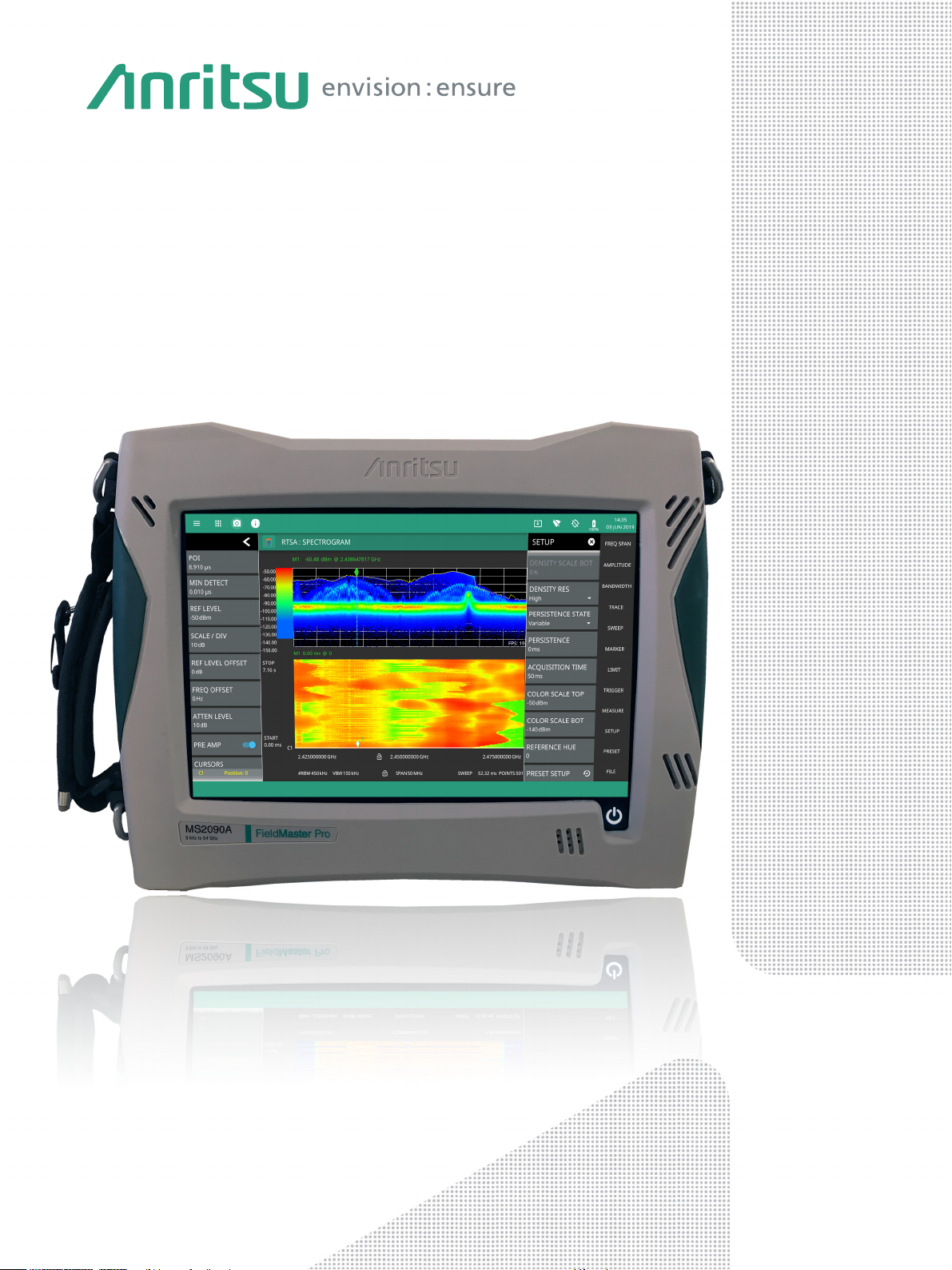
Field Master Pro™
High Performance Handheld
Spectrum Analyzer
MS2090A
9 kHz to 9 GHz, 14 GHz, 20 GHz, 26.5 GHz, 32 GHz, 43.5 GHz, 54 GHz
Technical Data Sheet
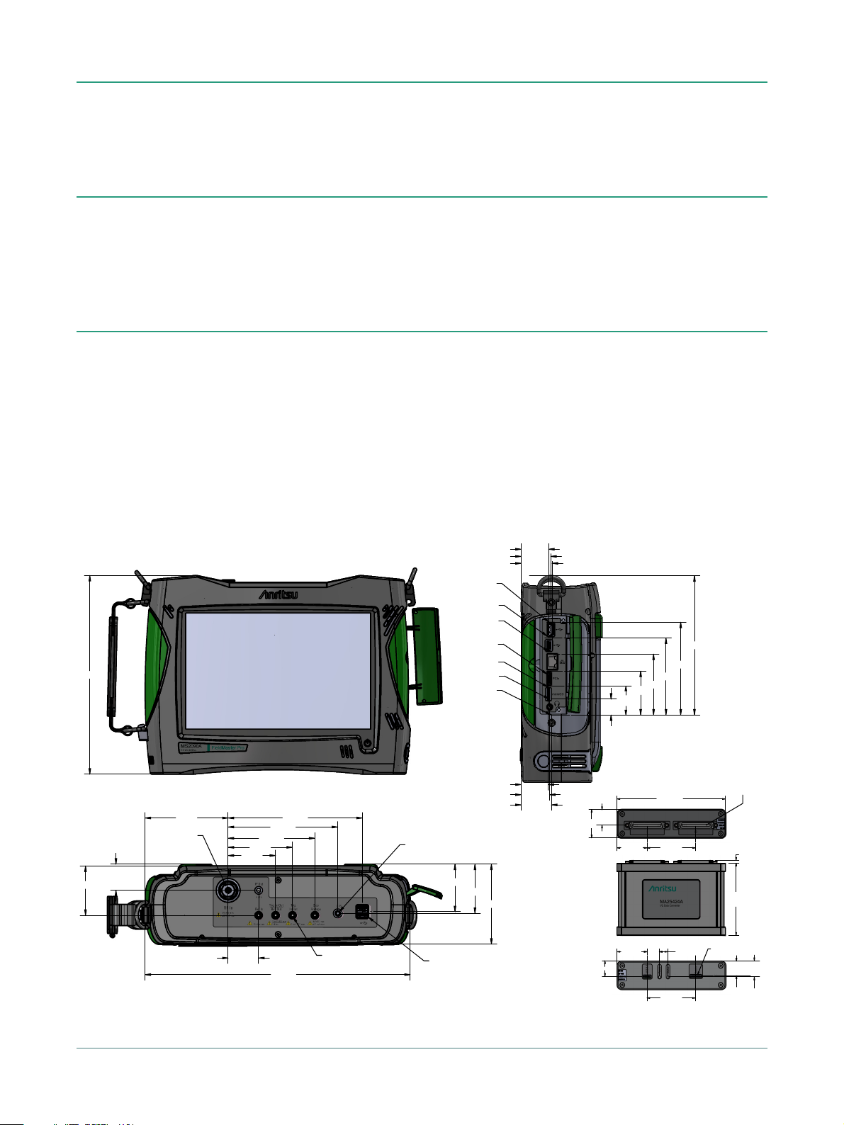
MS2090A Technical Data
234.89
313.42
98.23
36.04
56.04
76.04
102.54
129.54
58.32
31.00
58.17
94.56
158.54
56.27
SMA CONNECTOR
Dimensions in mm
SMB CONNECTOR
5X
USB CONNECTOR
"N", "K", "V"
CONNECTOR
34.89
32.42
36.59
35.82
33.42
31.94
164.63
18.75
33.77
51.91
71.94
91.07
109.70
USB C
USB 3.0
ETHERNET
PHONE JACK
DC JACK
MICRO SD
PCIe
MS2090A
MA25424A
128.30
33.43
18.63
57.32 35.49
50 PINS MDR
CONNECTOR, 2X
10.01
18.63
57.32
18.40
35.49
14.61
17.44
DATA OUT
CONNECTOR
85.46
3.40
Introduction
Anritsu is proud to introduce the world’s most advanced handheld spectrum analyzer with real-time spectrum analysis
capability. With frequency coverage up to 54 GHz, the new Field Master Pro™ MS2090A completely redefines the standards
for portable handheld analyzers, setting another new industry benchmark for performance and accuracy. The new
MS2090A is the culmination of over 60 years of microwave test and measurement equipment development, using the very
latest technologies to deliver accuracy and precision in measurements previously reserved only for benchtop instruments.
Instrument Highlights
• Modulation Bandwidth: up to 110 MHz
• Dynamic Range: >106dB in 1Hz RBW
• DANL: –164 dBm in 1 Hz RBW
• Phase Noise: –106 dBc/Hz @ 10 kHz offset at 1 GHz
• Resolution Bandwidth (RBW): 1 Hz up to 10 MHz
• RTSA with 2.05 µs POI
Capabilities and Functional Highlights
Wireless Measurements
• 5GNR FDD and TDD Analyzer
• Real Time Spectrum Analyzer
• LTE FDD and TDD Analyzer
• Spectrogram
• Zero Span IF Output
• Gated Sweep
• IQ Waveform Capture/Streaming
• Pulse Profile Measurements
• AM/FM Audio Demodulation
• Electromagnetic Field (EMF) Measurements
• EIRP
• Field Strength
• Occupied Bandwidth
• Channel Power
• Adjacent Channel Power
• Spectral Emissions Mask
• Signal Strength and RSSI
• Carrier Aggregation
• Full-band Preamplifiers
• Operation to +55 ºC: Full Performance on AC or Battery
• GNSS (GPS, GLONASS, Galileo)
• USB 3.0
• 10.1" Capacitive Touchscreen
• Two Hour Battery
• Signal Mapper (MA8100A)
• Coverage Mapping
• Trace Recording/Playback
2 of 26 PN: 11410-01000 Rev. R MS2090A TDS

Technical Data MS2090A
Table of Contents
Definitions. . . . . . . . . . . . . . . . . . . . . . . . . . . . . . . . . . . . . . . . . . . . . . . . . . . . . . . . . . . . . . . . . . . . . . . . . . . . . . . . . . . . . 3
Standard Spectrum Analyzer . . . . . . . . . . . . . . . . . . . . . . . . . . . . . . . . . . . . . . . . . . . . . . . . . . . . . . . . . . . . . . . . . . . . . 4
Real-Time Spectrum Analyzer (Option 199). . . . . . . . . . . . . . . . . . . . . . . . . . . . . . . . . . . . . . . . . . . . . . . . . . . . . . . . . 5
Spectrum Analyzer Performance . . . . . . . . . . . . . . . . . . . . . . . . . . . . . . . . . . . . . . . . . . . . . . . . . . . . . . . . . . . . . . . . . 6
Interference Finder and AM/FM Audio Demodulation (Option 24) . . . . . . . . . . . . . . . . . . . . . . . . . . . . . . . . . . . . . 8
GPS Receiver (Option 31) . . . . . . . . . . . . . . . . . . . . . . . . . . . . . . . . . . . . . . . . . . . . . . . . . . . . . . . . . . . . . . . . . . . . . . . . 8
Zero Span IF Output (Option 89) . . . . . . . . . . . . . . . . . . . . . . . . . . . . . . . . . . . . . . . . . . . . . . . . . . . . . . . . . . . . . . . . . . 8
Gated Sweep (Option 90) . . . . . . . . . . . . . . . . . . . . . . . . . . . . . . . . . . . . . . . . . . . . . . . . . . . . . . . . . . . . . . . . . . . . . . . . 8
IQ Waveform Capture (Option 124/126) . . . . . . . . . . . . . . . . . . . . . . . . . . . . . . . . . . . . . . . . . . . . . . . . . . . . . . . . . . . 9
IQ Waveform Streaming (Option 125/127) . . . . . . . . . . . . . . . . . . . . . . . . . . . . . . . . . . . . . . . . . . . . . . . . . . . . . . . . . 9
Pulse Analyzer (Option 421) . . . . . . . . . . . . . . . . . . . . . . . . . . . . . . . . . . . . . . . . . . . . . . . . . . . . . . . . . . . . . . . . . . . . . 10
Coverage Mapping (Option 431) . . . . . . . . . . . . . . . . . . . . . . . . . . . . . . . . . . . . . . . . . . . . . . . . . . . . . . . . . . . . . . . . . 11
Electromagnetic Field (EMF) Measurement (Option 444) . . . . . . . . . . . . . . . . . . . . . . . . . . . . . . . . . . . . . . . . . . . . 11
Electromagnetic Field (EMF) Meter (Option 445) . . . . . . . . . . . . . . . . . . . . . . . . . . . . . . . . . . . . . . . . . . . . . . . . . . . 11
LTE FDD/TDD Signal Analyzer (Option 883) . . . . . . . . . . . . . . . . . . . . . . . . . . . . . . . . . . . . . . . . . . . . . . . . . . . . . . . . 12
5GNR FDD/TDD Signal Analyzer (Option 888) . . . . . . . . . . . . . . . . . . . . . . . . . . . . . . . . . . . . . . . . . . . . . . . . . . . . . . 13
General Specifications . . . . . . . . . . . . . . . . . . . . . . . . . . . . . . . . . . . . . . . . . . . . . . . . . . . . . . . . . . . . . . . . . . . . . . . . . 14
Remote Interface Software . . . . . . . . . . . . . . . . . . . . . . . . . . . . . . . . . . . . . . . . . . . . . . . . . . . . . . . . . . . . . . . . . . . . . 15
Programmable Remote Control . . . . . . . . . . . . . . . . . . . . . . . . . . . . . . . . . . . . . . . . . . . . . . . . . . . . . . . . . . . . . . . . . 15
MA25424A IQ Data Converter . . . . . . . . . . . . . . . . . . . . . . . . . . . . . . . . . . . . . . . . . . . . . . . . . . . . . . . . . . . . . . . . . . .16
MA25101A IQ Streaming PCIe Kit . . . . . . . . . . . . . . . . . . . . . . . . . . . . . . . . . . . . . . . . . . . . . . . . . . . . . . . . . . . . . . . .16
Ordering Information – Instrument Options . . . . . . . . . . . . . . . . . . . . . . . . . . . . . . . . . . . . . . . . . . . . . . . . . . . . . . 17
Standard Accessories . . . . . . . . . . . . . . . . . . . . . . . . . . . . . . . . . . . . . . . . . . . . . . . . . . . . . . . . . . . . . . . . . . . . . . . . . . 18
Optional Accessories. . . . . . . . . . . . . . . . . . . . . . . . . . . . . . . . . . . . . . . . . . . . . . . . . . . . . . . . . . . . . . . . . . . . . . . . . . . 18
Definitions
Specifications All specifications and characteristics apply under the following conditions, unless otherwise stated:
Warm-Up Time After 10 minutes of warm-up time, where the instrument is left in the ON state.
Reference Signal When using internal reference signal.
Typical Performance Typical specifications are not tested and are not warranted. They are generally representative of
Nominal Performance Nominal specifications are design parameters; they are not tested and are not warranted.
Uncertainty A coverage factor of x1 is applied to the measurement uncertainties to facilitate comparison with other
Time Base Error Input Frequency × Frequency Reference Error
Calibration Cycle Calibration is within the recommended 12 month period
characteristic performance.
industry handheld analyzers.
All specifications in this data sheet are subject to change without notice. For the most current data sheet,
please visit the Anritsu web site:
www.anritsu.com
MS2090A TDS PN: 11410-01000 Rev. R 3 of 26

MS2090A Technical Data
Standard Spectrum Analyzer
Smart Measurements
Field Strength Measures field strength (dBm/m2, dBW/m2, dBµV/m2) with antenna gain vs. frequency plot
Channel Power Measures the total power and power spectral density within a specified bandwidth
Occupied Bandwidth Measures the 99 % to 1 % power channel of a signal
Adjacent Channel Power Measures the channel power of the adjacent channel
Spectral Emission Mask Standards based limits for wireless emissions
Setup Parameters
Frequency Center/Start/Stop, Frequency Step, Frequency Offset
Span Span (Manual/Increment 1, 2, 5), Full Span, Last Span, Zero Span
Amplitude Reference Level (Manual/Auto and Offset), Sale/Division, Y-Axis Unit (dBm, dBW, dBµV), Pre Amp,
Bandwidth RBW/VBW (Auto/Manual), VBW Type (Linear/Logarithmic), RBW:VBW Ratio, SPAN:RBW Ratio
Sweep Functions
Sweep Single/Continuous, Restart, Sweep Once, Sweep to N, Gated Sweep (see
Sweep Points 10 to 10,001 (1001 in zero span)
Sweep Time 60 ns to 3600 s in zero span
Sweep Time Accuracy ±2 % in zero span
Trace Functions
Traces Up to Six Traces
Trace Type Clear/Write, Average (2 to 1000), Max Hold, Min Hold, Rolling Average, Rolling Max Hold, Rolling Min Hold
Trace Mode Active, Hold/View, Blank
Detector Type per Trace Peak, RMS/Avg, Negative
Trace Record Record live samples with manual tagging to internal or external storage
Trace Playback Play recorded samples from internal or external storage; set playback interval
CSV Logging Record live or playback traces in CSV format for post processing
Attenuation (Auto/Manual)
on page 8
)
“Gated Sweep (Option 90)”
Trigger Functions
(zero span only)
Spectrogram
Trace Time/Position Cursor Up to Six Cursors (display historical trace data by trace position or time)
Marker Functions
Marker Measurements Power, Frequency, Time (Spectrogram)
Peak Search Setup Peak Threshold, Peak Excursion
Limit Line Functions
Limit Line Envelope Create Envelope, Update Envelope, Points (41 max), Offset, Shape Square/Slope
Sources Free Run, Video, External 1, External 2, Periodic
Settings Level, Delay, Holdoff, Slope, Hysteresis
Color Setup Set Color Top/Bottom Range, Set Color Reference Hue
Markers Up to 12 Markers
Marker Mode Normal, Delta, Fixed
Delta Marker Relative to any Normal or Fixed Marker
Marker Function None, Noise, Counter Marker
Marker Trace Assign Marker to any Trace
Peak Search Peak Search, Next Peak, Next Peak Left, Next Peak Right, Next Point Left, Next Point Right
→
Marker
Marker Table Up to 12 Markers Showing Marker Mode, Function, Trace, Frequency, Amplitude, Delta Frequency & Offset
Limit Setup Upper/Lower, Limit On/Off, Limit Alarm On/Off, Set Default Limit Line, Absolute/Relative, Mirror On/Off,
Limit Line Edit Frequency, Amplitude, Add Point, Add Vertical, Delete Point, Next Point Left/Right
Limit Line Move To Current Center Frequency, By dB or Hz, To Marker 1, Offset from Marker 1
Mkr → Center, Mkr → Ref Level
Default Limit
4 of 26 PN: 11410-01000 Rev. R MS2090A TDS

Technical Data MS2090A
Real-Time Spectrum Analyzer (Option 199)
Setup Parameters
Frequency Center/Start/Stop, Frequency Step, Frequency Offset
Span Span, Full Span (max span: 22 MHz standard, 55 MHz with option 103, 110 MHz with option 104)
Amplitude Reference Level (Manual/Auto and Offset), Sale/Division, Y-Axis Unit (dBm, dBW, dBµV), Pre Amp,
Bandwidth RBW (span dependent), Auto RBW, Span:RBW Ratio
Probability of Intercept Analysis Bandwidth Density Resolution Span RBW POI
Density Color Set Color Top/Bottom Range, Auto Scale
Persistence Infinite or Variable from 0 to 10 s
Acquisition Time 50 ms to 5 s
FFT Rate 527,000 FFT/s (normal resolution), 263,000 FFT/s (high resolution)
Minimum Detectable Signal 5 ns
Sweep Functions
Sweep Single/Continuous, Sweep Once
Attenuation (Auto/Manual)
20 MHz (Standard)
50 MHz (Opt. 103)
110 MHz (Opt. 104)
Normal
High
Normal
High
Normal
High
22 MHz
55 MHz
110 MHz
10 MHz
25 MHz
40 MHz
2.520 µs
4.420 µs
2.210 µs
4.110 µs
2.055 µs
3.950 µs
Trace Functions
Detector Type per Trace Peak, Sample, Negative
Spectrogram
Trace Time/Position Cursor Up to Six Cursors (display historical trace data by trace position or time)
Marker Functions
Marker Measurements Power, Frequency, Time (Spectrogram)
Peak Search Setup Peak Threshold, Peak Excursion
Limit Line Functions
Limit Line Envelope Create Envelope, Update Envelope, Points (41 max), Offset, Shape Square/Slope
Traces Up to Six Traces
Trace Type Clear/Write, Average (2 to 1000), Max Hold, Min Hold, Rolling Average, Rolling Max Hold, Rolling Min Hold
Trace Mode Active, Hold/View, Blank
Color Setup Set Color Top/Bottom Range, Set Color Reference Hue
Markers Up to 12 Markers
Marker Mode Normal, Delta, Fixed
Delta Marker Relative to any Normal or Fixed Marker
Marker Function None, Noise
Marker Trace Assign Marker to any Trace
Peak Search Peak Search, Next Peak, Next Peak Left, Next Peak Right, Next Point Left, Next Point Right
→
Marker
Marker Table Up to 12 Markers Showing Marker Mode, Function, Trace, Frequency, Amplitude, Delta Frequency & Offset
Limit Setup Upper/Lower, Limit On/Off, Limit Alarm On/Off, Set Default Limit Line, Absolute/Relative, Mirror On/Off,
Limit Line Edit Frequency, Amplitude, Add Point, Add Vertical, Delete Point, Next Point Left/Right
Limit Line Move To Current Center Frequency, By dB or Hz, To Marker 1, Offset from Marker 1
Mkr → Center, Mkr → Ref Level
Default Limit
MS2090A TDS PN: 11410-01000 Rev. R 5 of 26

MS2090A Technical Data
Spectrum Analyzer Performance
Frequency
(usable to 0 Hz)
MS2090A-0709 9 kHz to 9 GHz (Option 709)
MS2090A-0714 9 kHz to 14 GHz (Option 714)
MS2090A-0720 9 kHz to 20 GHz (Option 720)
MS2090A-0726 9 kHz to 26.5 GHz (Option 726)
MS2090A-0732 9 kHz to 32 GHz (Option 732)
MS2090A-0743 9 kHz to 43.5 GHz (Option 743)
MS2090A-0754 9 kHz to 54 GHz (Option 754)
Tuning Resolution 1 Hz
Span 10 Hz to max frequency, Zero Span
Frequency Reference Internal, GPS, External
Internal Frequency Reference Aging: ± 1.0 x 10
External Frequency Reference 10 MHz, 0 dBm to +10 dBm
Bandwidth
Analysis Bandwidth 20 MHz (standard), 50 MHz (Option 103), or 110 MHz (Option 104)
RTSA Bandwidth 22 MHz (standard), 55 MHz (Option 103), 110 MHz (Option 104)
Resolution Bandwidth (RBW) 1 Hz to 10 MHz (in RTSA, minimum RBW varies by span, max is 40 MHz)
Video Bandwidth (VBW) 0.1 Hz to 10 MHz
VBW/Average Type Linear/Log
Spectral Purity – SSB Phase Noise
Offset from 1 GHz
10 kHz
100 kHz
1MHz
10 MHz
–6
per 10 years
–6
Accuracy: ± 0.3 x 10
“GPS Receiver (Option 31)” on page 8
(see
Maximum
–102 dBc/Hz
–106 dBc/Hz
–111 dBc/Hz
–123 dBc/Hz
(25°C ±25°C) plus aging
Typical
–106 dBc/Hz
–110 dBc/Hz
–116 dBc/Hz
–129 dBc/Hz
for improved accuracy)
Spurs
(0 dB input attenuation)
Residual Spurs (RF input terminated)
<14GHz
14 to 20 GHz
>20 to 32GHz
>32 to 54GHz
Input-Related Spurious (–30 dBm input) Maximum
a. Instrument centered on single signal, span < 1.7 GHz, 0 dB input attenuation.
Preamp = Off
–90 dBm, maximum
–85 dBm, maximum
–80 dBm, maximum
–80 dBm, maximum
a
–60 dBc
Preamp = On
–100 dBm, maximum
–100 dBm, maximum
–100 dBm, maximum
–95 dBm, maximum
Typical
–70 dBc
6 of 26 PN: 11410-01000 Rev. R MS2090A TDS

Technical Data MS2090A
Amplitude Ranges
Dynamic Range >106 dB minimum at 2.4 GHz, 2/3 (TOI-DANL) in 1 Hz RBW
Measurement Range DANL to +30 dBm
Display Range 1 to 15 dB/div in 1 dB steps, ten divisions displayed
Reference Level Range –150 dBm to +30 dBm
Attenuator Resolution 0 to 65 dB, 5 dB steps
Reference Level Offset 99.9 dB external loss to 99.9 dB external gain
Amplitude Units dBm, dBm/m
Maximum Continuous Input +30 dBm peak typical, ± 50 VDC (≥ 10 dB attenuation)
+23 dBm peak typical, ± 50 VDC (< 10 dB attenuation)
+10 dBm peak typical, ± 50 VDC (preamp = On)
2
, dBW/m2, dBµV
Amplitude Accuracy
9 GHz to 20 GHz Instruments Maximum Typical Maximum Typical
26.5 GHz to 54 GHz Instruments
(10 dB attenuation, -50 dBm ≤ input signal ≤ -10 dBm , 1 kHz RBW, auto-coupled, excl uding effects of VSW R, noise, and spu rs)
9kHz to 14GHz
>14GHz to 18GHz
>18GHz to 20GHz
9kHz to 14GHz
>14GHz to 20GHz
>20GHz to 43.5GHz
>43.5GHz to 54GHz
Displayed Average Noise Level (DANL)
preamp On, auto attenuation On)
9 GHz to 20 GHz Instruments Maximum Typical Maximum Typical
10 MHz to 4 GHz
>4GHz to 9GHz
>9GHz to 14GHz
> 14 GHz to 20 GHz
26.5 GHz to 54 GHz Instruments
10 MHz to 4 GHz
>4GHz to 9GHz
>9GHz to 14GHz
> 14 GHz to 20 GHz
> 20 GHz to 32 GHz
> 32 GHz to 43.5 GHz
> 43.5 GHz to 54 GHz
20 °C to 30 °C (after 30 minute warm-up) –10 °C to 55 °C (after 60 minute warm-up)
±1.3dB
±1.3dB
–
±1.3dB
±1.3dB
±1.8dB
±1.8dB
(RMS detection, VBW/Avg type = Log, reference level = –20 dBm for preamp Off and –50 dBm for
Preamp = Off Preamp = On
–145 dBm
–142 dBm
–136 dBm
–138 dBm
–145 dBm
–142 dBm
–136 dBm
–138 dBm
–135 dBm
–135 dBm
–130 dBm
±0.5dB
±0.5dB
±1.0dB
±0.5dB
±0.5dB
±0.5dB
±0.5dB
–148 dBm
–145 dBm
–139 dBm
–144 dBm
–148 dBm
–145 dBm
–139 dBm
–142 dBm
–140 dBm
–140 dBm
–134 dBm
±2.0dB
±2.0dB
–
±2.0dB
±2.0dB
±2.5dB
±2.5dB
–161 dBm
–159 dBm
–156 dBm
–156 dBm
–161 dBm
–159 dBm
–156 dBm
–156 dBm
–154 dBm
–152 dBm
–147 dBm
±0.5dB
±0.5dB
±1.0dB
±0.5dB
±0.5dB
±0.5dB
±0.5dB
–164 dBm
–162 dBm
–159 dBm
–161 dBm
–164 dBm
–162 dBm
–159 dBm
–159 dBm
–159 dBm
–154 dBm
–151 dBm
Third-Order Intercept (TOI)
50 MHz to < 9 GHz +15 dBm typical
9 GHz to 20 GHz +20 dBm typical
> 20 GHz to 32 GHz +11 dBm typical
> 32 GHz to 54 GHz +15 dBm typical
P1dB
(nominal)
4 GHz to 20 GHz +12 dBm
>20GHz to 32GHz +7dBm
> 32 GHz to 54 GHz +12 dBm
Second Harmonic Distortion
VSWR
(≥ 10 dB input attenuation)
20 GHz to 54 GHz 2.0:1 typical
(–20 dBm tones 2 MHz apart, 0 dB input attenuation, preamp OFF, reference level –20 dBm)
2.4 GHz +14 dBm minimum
<4GHz +5dBm
(0 dB input attenuation, –30 dBm input)
50 MHz –75 dBc maximum
< 10 GHz –80 dBc typical
≥ 10 GHz –75 dBc typical
< 20 GHz 1.5:1 typical
MS2090A TDS PN: 11410-01000 Rev. R 7 of 26

MS2090A Technical Data
Interference Finder and AM/FM Audio Demodulation (Option 24)
Interference Finder
(for use with directional antennas, sold separately)
Setup Integration Bandwidth, Power Limit, MAX/MIN Level, Volume
Audio Tone 20 Hz to 20 kHz
AM/FM Audio Demodulation
Demod Frequency Full range of instrument
Audio Demodulation AM, USB, LSB, Widband FM, Narrowband FM
Markers Selectable demodulation marker (1 to 12)
Audio Toggle On/Off
Volume Set 0% to 25%
Record Audio Record audio up to 100,000 s (dependent on instrument memory)
Squelch Level –120 dBm to +30 dBm (set RF level threshold to break audio silence)
GPS Receiver (Option 31)
Supported Satellite Systems GPS, GNSS (includes GPS, GLONASS, Galileo)
GPS Time/Location Indicator UTC Time, Latitude, Longitude, and Altitude on display (UTC Time and Altitude on GPS Info display)
High Frequency Accuracy < ± 2.5 x 10
(requires external GPS antenna, sold separately)
Setup On/Off, Antenna Voltage 3.3 V/5.0 V, GPS Info
<±5.0 x 10
Connector SMA, female
Zero Span IF Output (Option 89)
Center Frequency 325 MHz (nominal, FFT capture BW ≤ 32 MHz)
Reference Level –57 dBm to +30 dBm (Preamp Off)
Mode Spectrum Analyzer/Zero Span only
300 MHz (nominal, FFT capture BW > 100 MHz, requires Option 103 or 104)
Output Level –4 dBm (nominal, –20 dBm input level, 0 dB input attenuation, preamp Off, 10 MHz input frequency)
IF Bandwidth ≤32 MHz; ≤110 MHz with Option 103 or 104
Rise Time <20 ns
Connector SMB(m), 50 Ω
Spectrum is inverted in certain input RF bands.
–87 dBm to –40 dBm (Preamp On)
–8
with GPS On, 3 minutes after satellite lock in selected mode (GPS antenna connected)
–8
24 hour holdover accuracy, 0 °C to 50 °C ambient temperature (GPS antenna disconnected)
Gated Sweep (Option 90)
Power vs. Time, Display Length 100 µs to 200 ms
Gate Source GPS
Frame Time 1 s, 20 ms, 10 ms
Gate Delay up to 200 ms
Gate Length 1 µs up to 200 ms
8 of 26 PN: 11410-01000 Rev. R MS2090A TDS

Technical Data MS2090A
IQ Waveform Capture (Option 124/126)
(Option 126 is non-export controlled and limits bit depth to 8 or 10 bits when bandwidth is 110 MHz)
IQ Capture
Mode Spectrum Analyzer, RTSA
Capture Mode Single or Continuous
Trigger Free Run, External (Rising/Falling), Interval, Level
Trigger Settings Delay (negative in RTSA mode only)
Maximum Sample Rate
Maximum Signal Bandwidth
IQ Capture Time
Signal Bandwidth IQ Sample Rate IQ Bit Resolution Mode
(MHz) (MSPS) 32 bit 16 bit 10 bit 8 bit SPA RTSA
110 200 1.34 s 2.68 s 4.29 s 5.37 s x x
100 122.88 2.18 s 4.37 s 6.99 s 8.74 s x
2.5 3.125 1.43 min 2.86 min 4.58 min 5.73 min x x
1.5 1.92 2.33 min 4.66 min 7.46 min 9.32 min x
1.25 1.5625 2.86 min 5.73 min 9.16 min 11.45 min x x
0.28 0.36 12.43 min 24.86 min 39.77 min 49.71 min x
0.036 0.045 99.42 min 198.84 min 318.15 min 397.68 min x
a. Option Dependent: Standard Analysis Bandwidth up to 20 MHz, Option 103 up to 50 MHz, Option 104 up to 110 MHz.
Bit Resolution 8, 10, 16, or 32-bit
Total Capture Memory 2 GB
Typical Maximum
80 100 2.68 s 5.37 s 8.59 s 10.74 s x x
74 92.16 2.91 s 5.83 s 9.32 s 11.65 s x
50 61.44 4.37 s 8.74 s 13.98 s 17.48 s x
40 50 5.37 s 10.74 s 17.18 s 21.47 s x x
36 46.08 5.83 s 11.65 s 18.64 s 23.3 s x
25 30.72 8.74 s 17.48 s 27.96 s 34.95 s x
20 25 10.74 s 21.47 s 34.36 s 42.95 s x x
18 23.04 11.65 s 23.30 s 37.28 s 46.6 s x
12 15.36 17.48 s 34.95 s 55.92 s 1.17 min x
10 12.5 21.47 s 42.95 s 1.15 min 1.43 min x x
6 7.68 34.95 s 1.17 min 1.86 min 2.33 min x
5 6.25 42.95 s 1.43 min 2.29 min 2.86 min x x
3 3.84 1.17 min 2.33 min 3.73 min 4.66 min x
a
a
200 MHz
110 MHz
a
IQ Waveform Streaming (Option 125/127)
100 MHz BW or less.)
Bit Resolution 8, 10, 16, or 32-bit
Ethernet Port Maximum gapless bandwidth depends on network transfer speed
USB Port Requires USB 3.0 solid state drive.
Device formatted as external file system (ext4). Maximum gapless streaming bandwidth:
8 bit: 100 MHz BW, 122.88 MSPS sample rate
10 bit: 80 MHz BW, 100 MSPS sample rate
16 bit: 50 MHz BW, 61.44 MSPS
32 bit: 25 MHz BW, 30.72 MSPS
Device formatted as extensible file allocation table system (exFAT) with 32 MB allocation unit size.
Maximum gapless streaming bandwidth:
8 bit: 80 MHz BW, 100 MSPS sample rate
10 bit: 50 MHz BW, 61.44 MSPS sample rate
16 bit: 40 MHz BW, 50 MSPS sample rate
32 bit: 20 MHz BW, 25 MSPS sample rate
Data Out Port Gapless streaming of 110 MHz bandwidth at 16-bit resolution or 100 MHz bandwidth at 32-bit resolution
(requires MA25101A IQ Streaming PCIe kit and compatible PC)
Stream to Bird IQC5000B at 16-bit resolution only, full bandwidth/sample rate (requires MA25424A receiver)
(requires Option 124 or 126; Option 127 is non-export controlled and limits streams to
MS2090A TDS PN: 11410-01000 Rev. R 9 of 26

MS2090A Technical Data
Pulse Analyzer (Option 421)
Pulse Measurements
First Transition Characteristics Transition Duration, Duration Instant, Low Reference Instant, High Reference Instant,
Second Transition Characteristics Transition Duration, Duration Instant, Low Reference Instant, High Reference Instant
DANL and dynamic range are the same as the Spectrum Analyzer Performance.
Pulse measurements in accordance with IEEE Standard for Pulses, Transitions, and Related Waveforms (2011) section 5.2.1.
Power Measurements Average, Peak, Wave Average, Peak Wave Average, Pulse Average
Pulse Characteristics Duration, Center, Tilt, Period, Off Time, Duty Factor, Frequency
Pre Transition Overshoot, Post Transition Overshoot,
Pre Transition Undershoot, Post Transition Undershoot
Pulse View Settings Pulse Analyzer (enables pulse analyzer measurements above), Pulse Viewer (removes pulse analyzer
Rise Time (trace averages set to 100; RBW:VBW = 1)
measurements and enables standard marker measurements)
30 ns, 40 MHz RBW (Option 104)
60 ns, 25 MHz RBW (Option 103)
100 ns, 10 MHz RBW (Standard)
Setup Parameters
Frequency Center, Step Size, Offset
Amplitude Reference Level (Manual/Auto and Offset), Sale/Division, Y-Axis Unit (dBm, dBW, dBµV), Pre Amp,
Bandwidth RBW/VBW (Auto/Manual), VBW Type (Linear/Logarithmic), RBW:VBW Ratio, SPAN:RBW Ratio
Pulse Setup Pulse Level Type (Auto/User) User TOP (S2), User BOTTOM (S1),
Attenuation (Auto/Manual)
Pulse Reference High (%), Pulse Reference Low (%), Pulse Duration Reference (%)
Trace Functions
Traces Up to Six Traces
Trace Type Clear/Write, Min Hold, Max Hold, Average, Rolling Max Hold, Rolling Min Hold, Rolling Average
Detector Type per Trace Peak, Negative, Sample
Trace Mode Active, Hold/View, Blank
Sweep Functions
Sweep Single/Continuous, Restart, Sweep Once, Sweep to N, Sweep Time
Sweep Points 1001
Sweep Time 60 ns to 3600 s
Sweep Time Accuracy ±2 %
Marker Functions
Marker Measurements Power, Time
Trigger Functions
Pulse Simulation
(enabled only in Pulse Viewer)
Markers Up to 12 Markers
Marker Mode Normal, Delta, Fixed
Delta Marker Relative to any Normal or Fixed Marker
Marker Function None, Noise
Marker Trace Assign Marker to any Trace
Peak Search Peak Search, Next Peak, Next Peak Left, Next Peak Right, Next Point Left, Next Point Right
Peak Search Setup Peak Threshold, Peak Excursion
→
Marker
Marker Table Up to 12 Markers Showing Marker Mode, Function, Trace, Time, Amplitude, Delta Time & Offset
Sources Free Run, Video, External 1, External 2
Settings Level, Delay, Holdoff, Periodic, Slope, Hysteresis
Trigger Jitter 20 ns
Provides visual and measurement data of simulated pulse types.
Waveform Types Single Positive, Single Negative, Train, Double
Settings Amplitude (High and Low), Period, Duty Factor
Mkr → Center, Mkr → Ref Level
10 of 26 PN: 11410-01000 Rev. R MS2090A TDS

Technical Data MS2090A
Coverage Mapping (Option 431)
(Spectrum Analyzer Only)
Measurements
Channel Power Plots channel power in dBm, dBW, dBµV
Spectral Density Plots spectral density in dBm/Hz, dBW/Hz, dBµV/Hz
RSSI Plots received signal strength indicator in dBm, dBW, dBµV
Field Strength Plots field strength in dBm/m
Power Flux Density Plots power flux density in dBm/m
2
, dBW/m2, dBµV/m2
2
/Hz, dBW/m2/Hz, dBµV/m2/Hz
Measurement Setup
Frequency (Excluding RSSI) Center/Start/Stop, Frequency Step, Frequency Offset
Span (Excluding RSSI) Span (Manual/Increment 1, 2, 5), Full Span, Last Span, Zero Span
Amplitude Reference Level (Manual/Auto and Offset), Sale/Division, Y-Axis Unit, Pre Amp, Attenuation (Auto/Manual)
Bandwidth RBW/VBW (Auto/Manual), VBW Type (Linear/Logarithmic), RBW:VBW Ratio, SPAN:RBW Ratio
Mapping Colors Customizable Amplitude Range Thresholds for Each Color
Point Distance or Time Setup Repeat Type: Time (1 s to 60 s) or Distance (1 m to 10,000 m), Distance Units: Meters or Feet
Electromagnetic Field (EMF) Measurement (Option 444)
The Spectrum Analyzer mode provides electromagnetic field strength measurements in three axis (X, Y, Z) with trace displays for each measurement and
tabular results.
Blue (Excellent), Green (Very Good), Yellow (Good), Orange (Fair), Red (Poor)
Save Setup, KML Points, PNG, Tab Delimited
Recall Setup, KML Points File
(requires a supported antenna)
Measurements/Settings
Setup Limit lines, Axis Dwell Time, Measurement Time, Measurement Count, Measurement Units, Data Logging
with storage location
Units dBm/m
Results Maximum, Minimum, and Average of all measurements conducted
Displayed Information Measurement progress, number of measurements taken, Pass/fail indicators
2
, dBW/m2
Frequency Range
Supported Antenna
2000-1800-R 9 kHz to 300 MHz
2000-1792-R 30 MHz to 3 GHz
2000-1791-R 700 MHz to 6 GHz
Electromagnetic Field (EMF) Meter (Option 445)
The EMF Meter mode provides electromagnetic field strength measurements in three axis (X, Y, Z) with bar graph for each measurement and tabular results.
(Requires a supported probe)
Measurements/Settings
Limit Standard (FCC Public, ICNIRP Public, ICNIRP Worker), Limit Mode (Lowest, Frequency), Alarm, Volume, Mute,
Preset
Supports the International Commission on Non-Ionizing Radiation Protection limit (ICNIRP)
Measure Selected sample (1 through 16), start sampling, clear results
Setup EMF Meter Calibration, Display probe info
Units mW/cm
Preset Preset Mode
Setup File Quick save, Save As, Recall (.stp file type)
Results (%) Maximum, Minimum, and Average of all samples (1 through 8)
Display Bar graph of each sample (1 through 16) with Standard Limit Line, Time (mm:ss)
2
Frequency Range
Supported Probe
2000-1985-R Isotropic EMF Probe, 20 MHz to 40 GHz (refer to data sheet 11410-01185)
MS2090A TDS PN: 11410-01000 Rev. R 11 of 26

MS2090A Technical Data
LTE FDD/TDD Signal Analyzer (Option 883)
General
Frequency Range 10 MHz to 54 GHz (option dependent)
Channel Bandwidth (MHz) 1.4, 3, 5, 10, 15, 20
Amplitude Auto Range, Reference Level, Scale/Division, Reference Level Offset
Input Signal Range –76 dBm to +10 dBm (≤20 GHz)
Sweep Single/Continuous
MIMO Antenna Setup Auto, Antenna 1, 2, 3, or 4
LTE Demodulation Summary
PCI Summary Measurements Physical Cell ID, Sector ID, Cell Group, Frequency Error, Time Offset, Cyclic Prefix, Status of Primary
Signal Power Measurements (dBm) Physical Broadcast Channel Power (PBCH), Sync Signal (SS), Reference Signal (RS), OFDM Symbol Transmit
Error Vector Magnitude Measurements (%) Physical Broadcast Channel (QPSK), Physical Downlink Shared Channel (QPSK),
Demod Summary View PCI, Sector ID, Cell Group, Frequency Error, Time Offset, Cyclic Prefix, Sync Status, Power (PBCH, SS, RS),
Time Alignment Error (TAE) View PCI, Sector ID, Cell Group, Frequency Error, Time Offset, Cyclic Prefix, Sync Status, TAE between each
Resource Block View PCI, Sector ID, Cell Group, Frequency Error, Time Offset, Cyclic Prefix, Sync Status, RB (number of active RBs,
Setup Parameters Antenna (Auto/1/2/3/4), Cyclic Prefix (Auto/Normal/Extended), Duplex Type (FDD/TDD),
RS Power Accuracy ± 1.0 dB typical (RF input –50 dBm to +10 dBm)
Frequency Error ± 10 Hz + time base error (99 % confidence level)
Residual EVM (rms) 2.0 % typical (E-UTRA Test Model 3.1, RF Input –50 dBm to +10 dBm)
–72 dBm to +10 dBm (>20 GHz)
Synchronization Signal (PSS), MIMO Time Alignment Error, Resource Block Power
Power (OSTP)
PDSCH (16-QAM/64-QAM/256-QAM)
EVM (PBCH(QPSK), PDSCH (QPSK, 16-QAM, 64-QAM, 256-QAM)
antenna pair, Power (RS, SS), EVM (RMS, PEAK)
Utilization, OSTP), EVM (QPSK, 16-QAM, 64-QAM, 256-QAM)
UL/DL Config (TDD only), CFI (Auto/CFI1/CFI2/CFI3)
LTE Multi PCI
Setup Parameters Cyclic Prefix (Auto/Normal/Extended), Duplex Type (FDD/TDD), UL/DL Config (TDD only),
Channel Power
Setup Parameters Integration Bandwidth, PSD Units (Hz/MHz), Power Limit (dBm), PSD Limit (dBm/Hz)
RF Channel Power Accuracy ± 1 dB typical (–50 dBm to +10 dBm)
Channel Spectrum
Setup Parameters OBW Power (%/dB), OBW Limit (Hz), Method (%/x dB)
Carrier Aggregation
PCI Measurements Physical-layer Cell ID (PCI), RS Power, EVM (% rms), Frequency Error (Hz)
Setup Parameters Carrier Count (up to eight), Antenna (Auto/1/2/3/4), Cyclic Prefix (Auto/Normal/Extended),
Control Channel
PCI Summary Measurements Physical Cell ID, Sector ID, Cell Group, Frequency Error, Time Offset, Cyclic Prefix, Status of Primary
Power Measurements Reference Signal (RS), P-Primary Synchronization Signal (P-SS), Secondary Synchronization Signal (S-SS),
Setup Parameters Antenna (Auto/1/2/3/4), Cyclic Prefix (Auto/Normal/Extended), Duplex Type (FDD/TDD),
Measurements Multiple Physical Cell IDs, Secondary Sync Signal Power (S-SS), Reference Signal Received Power (RSRP),
Graph Displays PCI, SINR, RSRP, RSRQ, SS Power
Measurements Total Channel Power, Total Power Spectral Density (PSD), Limit Test (Power and PSD)
Measurements Occupied Bandwidth (OBW), Total Power, Occupied Bandwidth, Limit Test (OBW)
Reference Signal Received Quality (RSRQ), Signal to Interference and Noise Ratio (SINR), Average Error
Vector Magnitude (EVM), Peak EVM, Frequency Error (Hz and PPM), Dominance
CFI (Auto/CFI1/CFI2/CFI3)
Duplex Type (FDD/TDD)
Synchronization Signal (PSS)
Physical Broadcast Channel (PBCH), Physical Control Format Indicator Channel (PCFICH), Physical Hybrid
Automatic Repeat Request Indicator Channel (PDCCH), Physical Downlink Control Channel (PDCCH), Total
Power per Resource Element and Power (dBm/watts), EVM (%)
UL/DL Config (TDD only), NG (1/6, 1/2, 1, 2)
Constellation
Measurements Constellation Display of PBCH or PDSCH
Setup Parameters Antenna (Auto/1/2/3/4), Cyclic Prefix (Auto/Normal/Extended), Duplex Type (FDD/TDD),
UL/DL Config (TDD only), CFI (Auto/CFI1/CFI2/CFI3), Modulation (PBCH/PDSCH), Data Format
(All/QPSK/16-QAM/64-QAM/256-QAM)
12 of 26 PN: 11410-01000 Rev. R MS2090A TDS

Technical Data MS2090A
5GNR FDD/TDD Signal Analyzer (Option 888)
General
Frequency Range 10 MHz to 54 GHz (option dependent)
Band Configuration Manual or selectable Band #, Absolute Radio Frequency Channel Number (ARFCN), Global Synchronization
Auto SSB Detect Searches 3GPP defined GSCN raster
Amplitude Auto Range, Reference Level, Scale/Division, Reference Level Offset, Attenuation Level (Auto/Manual),
Input Signal Range –76 dBm to +10 dBm (≤20 GHz)
Sweep Single/Continuous, Sweep Once
5GNR Demod Summary
Multi-Beam Measurements Physical-layer Cell ID, Beam Index, Sector ID, Cell Group, Frequency Error, Time Offset, SS-RSRP (dBm),
Single-Beam Measurements Physical Cell ID, Sector ID, Cell Group, Frequency Error, Time Offset, SS-RSRP (dBm), SS-RSRQ (dB),
Setup Parameters SINR Threshold (dB), Duplex Type (FDD/TDD)
RSRP Accuracy ± 1.0 dB typical
Residual EVM (rms) 2.0 % typical
Frequency Error < ± 2.0E-8 + time base error, typical
Raster Channel (GSCN), Channel Bandwidth (5 MHz to 100 MHz in steps of 5 MHz), SSB Offset, Subcarrier
Spacing (15, 30, 60, 120, 240 kHz), Mapping Pattern (Auto, P1, P2), Auto SSB Detect
Preamp
–72 dBm to +10 dBm (>20 GHz)
SS-RSRQ (dB), SS-SINR (dB), Sync and Demod Status Indicators, Beam Power (dBm)
SS-SINR (dB), Sync and Demod Status Indicators, Block Measurements (PSS, SSS, PBCH, PBCH-DMRS),
Average EVM, Peak EVM (@ subcarrier/symbol), Beam Power (dBm)
Views Multi Beam (up to 64), Single Beam
5GNR Multi PCI
Measurements Multiple Physical-layer Cell IDs, Beam Index, SS-RSRP (dBm), SS-RSRQ (dB), SS-SINR (dB), SS-EVM (%)
Views Multi PCI Beam Scanner (up to 64 beams), Table
Setup Parameters SINR Threshold (dB), Duplex Type (FDD/TDD)
5GNR RF EIRP
Measurements EIRP (Active, Horizontal/Vertical, Sum), Upper/Lower Limit Test
Views Normal (RF spectrum), Quick View (summary)
Setup Parameters Save (Horizontal/Vertical), Reset Sum, RX Antenna Gain, Distance to Antenna, Units (Meters/Feet),
5GNR RF Occupied Bandwidth
Measurements Occupied Bandwidth, Total Power, x dB Bandwidth, Tx Frequency Error, Limit Test
Setup Parameters Method: OBW Power (% and X dB), OBW Limit Test
5GNR RF Channel Power
Measurements Total Channel Power, Total PSD, Limit Test
Setup Parameters Integration Bandwidth, PSD Units, Power and PSD Limit Tests
RF Channel Power Accuracy ± 1 dB typical (–76 dBm to +10 dBm)
5GNR Carrier Aggregation
Component Carriers Up to Eight Component Carriers
PCI Measurements Sync status (PSS), Physical-layer Cell ID (PCI), RSRP Max, EVM (% rms), Frequency Error (Hz), Time Offset
Setup Parameters Carrier Count (up to 8), Duplex Type (FDD/TDD)
5GNR Constellation
Measurements Constellation Display of PBCH
Setup Parameters Modulation (QPSK), Data Format (PBCH), Beam Select, Reference Points
Beam Power (dBm)
Upper/Lower Limit Test, RX Cable Loss
View Normal (RF Spectrum)
View Normal (RF Spectrum)
MS2090A TDS PN: 11410-01000 Rev. R 13 of 26

MS2090A Technical Data
General Specifications
Setup Parameters
Screen Shot Settings Image capture size, Image header/footer
Option Configuration Enable options using file (USB)
Connectors
External Reference In SMB(m), 50 Ω, maximum input +10 dBm
External Reference Out SMB(m), 50 Ω, 10 MHz
Date and Time Date and Time settings, Time Zone settings, Time synced to Internet/GPS
Languages English
Display Brightness adjustment, Auto screen dimming shutoff timer (on/off), Color schemes (Standard, Inverted)
GPS see
Ethernet Ethernet (IP4 & IP6 formats), Type (DHCP, Static)
WLAN (Wi-Fi) 2x2 MIMO, 802.11 a/b/g/n/ac, On/Off, Auto detect wireless networks
Reset Factory Reset, Delete All User Files, Delete System Files, Master Reset, Diagnostics
Diagnostics Self Test, Service Tools, exportable event and system error logs
Save/Recall Measurement Setup, Screenshot Image (.PNG), Export Measurement data (Text, CSV), Location
File Management Save, Copy, Paste, Delete, Create New Folder, Set File Name and File Type, Rename
RF In MS2090A-0709, -0714, -0720: Type N(f), 50 Ω
GPS SMA(f)
External Power 5.5 mm barrel connector, 13.5 to 17.5 VDC, 5.0 A max
Ethernet Interface RJ45 connector for Ethernet 10/100/1000 Mbps (connect to PC or LAN for remote access and IQ streaming)
USB Interface USB 3 Type A (supports file transfer and IQ capture/streaming)
Headset Jack 3.5 mm 3-wire headset jack (functionality supported in future software update)
External Trigger SMB(m), 50 Ω, TTL-compatible levels, maximum input +5 VDC
IF Out SMB(m), 50 Ω (see
DC Bias Voltage SMB(m), Setup: On/Off, Voltage, Trip Reset
“GPS Receiver (Option 31)” on page 8
MS2090A-0726, -0732, -0743: Ruggedized Type K(m), 50 Ω
MS2090A-0754: Ruggedized Type V(m), 50 Ω
USB 3 Type C (USB-TMC)
“Zero Span IF Output (Option 89)” on page 8
Voltage Range: +1 V to +34 V, Resolution: 0.1 V
Max Current: 1 A, Max Power: 15 W
)
Display and Keyboard
Screen Strength IK08 (protected against a 5 joule impact)
Touch Gestures Pinch to zoom x (span), Drag in x (center frequency, markers, limit line points)
Battery
Battery Operation Two hour operation, typical
Charging Temperature Limit 0 °C to +45 °C, relative humidity ≤ 80 %
Display 10.1 inch capacitive touchscreen, 1280 x 800 resolution
Keyboard Common alphanumeric/symbolic keys and customizable EZ keyboard
Toolbar System menu, application drawer, shortcuts, screen capture, lock status (touchscreen), notification bar,
Wi-Fi status, GPS status, battery status, time and date
Type Li-Ion
14 of 26 PN: 11410-01000 Rev. R MS2090A TDS

Technical Data MS2090A
Regulatory Compliance
European Union EMC 2014/30/EU, EN 61326-1:2013, CISPR 11/EN 55011, IEC/EN 61000-4-3/4/5/6/8/11
Australia and New Zealand RCM AS/NZS 4417:2012
South Korea KCC-REM-A21-0004
Canada ICES-3(A)/NMB-3(A)
United States FCC ID: SQG-60SIPT
Low Voltage Directive 2014/35/EU
Safety EN 61010-1:2010
RoHS Directive 2011/65/EU
ICES-1(A)/NMB-1(A) with Option 6
Environmental
Operating Temperature Range –10 ºC to 55 ºC
Storage Temperature Range –51 ºC to 71 ºC
Maximum Relative Humidity 95 % RH at 30 ºC, non-condensing
Vibration, Sinusoidal 5 Hz to 55 Hz
Vibration, Random 10 Hz to 500 Hz
Half Sine Shock 30 g
Altitude 4600 meters, operating and non-operating
Explosive Atmosphere MIL-PRF-28800F Section 4.5.6.3
Warranty
Duration Standard three-year warranty
Size and Weight
Size 314 mm x 235 mm x 95 mm, (12.4 in x 9.25 in x 3.74 in)
Weight MS2090A-0709, -0714, -0720: 5.06 kg (11.15 lb)
Remote Interface Software
Functionality Full instrument graphical user interface control from a PC with simulated hardware support for on-screen
Interfaces Ethernet, WLAN
Programmable Remote Control
Functionality Full instrument programming control (except power on/off) via Ethernet and WLAN connectivity. See the
Programming Language Standard Commands for Programmable Instruments (SCPI)
Interfaces Ethernet, WLAN, USBTMC (USB C port)
MIL-PRF-28800F Class 2
n
MIL-STD-810G, Method 511.5, Procedure 1
One-year warranty on battery
MS2090A-0726, -0732, -0743, -0754: 5.4 kg (11.9 lb)
Free MS2090A software download from www.anritsu.com
measurement analysis
Programming Manual for details.
MS2090A TDS PN: 11410-01000 Rev. R 15 of 26

MS2090A Technical Data
MA25424A IQ Data Converter
IQ Streaming
(used for streaming IQ data components of a waveform from the MS2090A Data Out port to an IQC5000)
Shipping Contents MA25424A Module
Input Ports Data In (PCIe), USB (for power)
Output Port IEEE 1284-C, 50 pin
Data Throughput 200 MSPS @ 16 bit max
Power Consumption 3.33 W (USB 3.0)
(requires Options 124 and 125 or Options 126 and 127)
PCIe OCuLink I/O Data Cable
USB 3.0 Type A to Type C Cable
Mode Spectrum Analyzer, RTSA
Warranty
Duration Standard three-year warranty
Size and Weight
Size 128.3 mm x 33.43 mm x 88.86 mm
Weight 377 g (including cables)
MA25101A IQ Streaming PCIe Kit
IQ Streaming
Warranty
(used for streaming IQ data components of a waveform from the MS2090A Data Out port to a PC)
Shipping Contents PCIe Computer Card with mounting hardware
PCIe OCuLink I/O Data Cable
Software MX280006A IQ Acquisition Tool (download from www.anritsu.com)
Mode Spectrum Analyzer, RTSA, 5G, LTE
Input Ports Data In (PCIe) (use PC Ethernet for instrument control and low speed IQ data streaming)
Data Rate >800 MB/s max; 110 MHz @ 16 bits max
Duration 90 day warranty
(requires Option 125 or Option 127)
16 of 26 PN: 11410-01000 Rev. R MS2090A TDS

Technical Data MS2090A
Ordering Information – Instrument Options
Part Number Description
MS2090A Field Master Pro (Requires Option 709, 714, 720, 726, 732, 743, or 754)
Options
MS2090A-0709 Frequency Range 9 kHz to 9 GHz
MS2090A-0714 Frequency Range 9 kHz to 14 GHz
MS2090A-0720 Frequency Range 9 kHz to 20 GHz
MS2090A-0726 Frequency Range 9 kHz to 26.5 GHz
MS2090A-0732 Frequency Range 9 kHz to 32 GHz
MS2090A-0743 Frequency Range 9 kHz to 43.5 GHz
MS2090A-0754 Frequency Range 9 kHz to 54 GHz
MS2090A-0006 Remove Wi-Fi
MS2090A-0024 Interference Finder (requires directional antenna, sold separately)
MS2090A-0031 GPS Receiver (requires GPS antenna, sold separately)
MS2090A-0089 Zero Span IF Output
MS2090A-0090 Gated Sweep
MS2090A-0103 50 MHz Analysis Bandwidth
MS2090A-0104 100 MHz Analysis Bandwidth
MS2090A-0124 IQ Waveform Capture
MS2090A-0125 IQ Waveform Streaming (requires Option 124, MA25424A recommended)
MS2090A-0126 IQ Waveform Capture (non-export controlled)
MS2090A-0127 IQ Waveform Streaming (non-export controlled, requires Option 126, MA25424A recommended)
MS2090A-0128 Vector Signal Analysis Enabled (requires Option 124 or 126; use with MX280005A software)
MS2090A-0199 Real Time Spectrum Analyzer
MS2090A-0400 Vision Monitor Enabled
MS2090A-0407 Vision High-Speed Port Scanner Enabled
MS2090A-0421 Pulse Analyzer
MS2090A-0431 Coverage Mapping (requires GPS option MS2090A-0031)
MS2090A-0444 EMF Measurement (requires a compatible Anritsu isotropic antenna)
MS2090A-0445 EMF Meter Enabled (requires 2000-1985-R isotropic EMF probe)
MS2090A-0883 LTE FDD/TDD Measurements (requires GPS option MS2090A-0031)
MS2090A-0888 5GNR FDD/TDD Measurements (requires GPS option MS2090A-0031)
MS2090A-xxxx-0097 Accredited Calibration to ISO17025 and ANSI/NCSL Z540-1 (xxxx is the frequency option number)
MS2090A-xxxx-0098 Standard Calibration to ISO17025 and ANSI/NCSL Z540-1 (xxxx is the frequency option number)
MS2090A-xxxx-0099
Premium Calibration to ISO17025 and ANSI/NCSL Z540-1 plus test data
(xxxx is the frequency option number)
MS2090A TDS PN: 11410-01000 Rev. R 17 of 26

MS2090A Technical Data
Standard Accessories
Accessory Description Accessory Description
3-2000-1928
Shoulder Strap
2000-1931-R
Stylus with replaceable fiber tip
633-75
Li-Ion Battery
40-204-R
AC/DC Power Supply (Field Master Series)
Certificate of Calibration and Conformance
(included with instrument)
2000-1371-R
Ethernet Cable, 2 m
2000-1859-R
USB Cable, USB 3.0 Type-A to Type-C, 1 m
2000-1938-R
SMB Plug to BNC Jack Adapter (qty 3)
806-366-R
BNC to SMB Cable, 1 m
2000-1938-R
SMB Plug to BNC Jack Adapter (qty 3)
Optional Accessories
Miscellaneous Accessories
Accessory Description Accessory Description
2000-1945-R
MS2090A Soft Case
67135
Anritsu Backpack (for Handheld Instrument and PC)
760-243-R
Large Transit Case with Wheels and Handle
56 cm x 45.5 cm x 26.5 cm (22.07" x 17.92" x 10.42")
40-207-R
Automotive DC/DC Power Adapter
MA25401A
Atomic Clock External 10 MHz Frequency Reference
(see MA25401A Technical Data Sheet, PN:
11410-01134 for details)
MA25424A
I/Q Data Converter Module
Includes:
2000-2030-R PCIe OCuLink I/O Data Cable
2000-1859-R USB 3.0 Type A to Type C Cable
MA25101A
IQ Streaming PCIe Kit
Includes:
PCIe Card with mounting hardware
2000-2030-R PCIe OCuLink I/O Data Cable
2000-1374-R
External Dual Charger for Li-lon Batteries
2000-2048-R
Screen Protector
18 of 26 PN: 11410-01000 Rev. R MS2090A TDS

Technical Data MS2090A
GPS Antennas
Accessory Description Accessory Description
(active)
2000-1528-R
Magnet Mount, SMA(m) with 5 m (16.4 ft) cable,
requires 5 VDC
2000-1652-R
Magnet Mount, SMA(m) with 0.3 m (1 ft) cable,
requires 3.3VDC or 5VDC
2000-1760-R
Miniature Antenna, SMA(m), requires 2.5 VDC to
3.7 VDC
Directional Antennas
Accessory Description Accessory Description
2000-1411-R
824 MHz to 896 MHz, N(f), 12.3 dBi, Yagi
2000-1412-R
885 MHz to 975 MHz, N(f), 12.6 dBi, Yagi
2000-1413-R
1710 MHz to 1880 MHz, N(f), 12.3 dBi. Yagi
2000-1414-R
1850 MHz to 1990 MHz, N(f), 11.4 dBi, Yagi
2000-1726-R
Antenna, 2500 MHz to 2700 MHz, N(f), 14.1 dBi, Yagi
2000-1747-R
Antenna, Log Periodic, 300 MHz to 7000 MHz, N(f), 5.1
dBi, typical
2000-1748-R
Antenna, Log Periodic, 1 GHz to 18 GHz, N(f), 6 dBi,
typical
2000-1777-R
Portable Directional Antenna, 9 kHz to 20 MHz, N(f)
(requires port extender 2000-1798-R when used with
MA2700A)
2000-1415-R
2400 MHz to 2500 MHz, N(f), 14.1 dBi, Yagi
2000-1416-R
1920 MHz to 2170 MHz, N(f), 14.3 dBi, Yagi
2000-1659-R
698 MHz to 787 MHz, N(f), 10.1 dBi, Yagi
2000-1660-R
1425 MHz to 1535 MHz, N(f), 14.3 dBi, Yagi
2000-1715-R
Directional Antenna, 698 MHz to 2500 MHz, N(f), gain
of 2 dBi to 10 dBi, typical
2000-1778-R
Portable Directional Antenna, 20 MHz to 200 MHz,
N(f)
(requires port extender 2000-1798-R when used with
MA2700A)
2000-1779-R
Portable Directional Antenna, 200 MHz to 500 MHz,
N(f)
(requires port extender 2000-1798-R when used with
MA2700A)
2000-1812-R
Portable Yagi Antenna, 450 MHz to 512 MHz, N(f), 7.1
dBi
2000-1825-R
Portable Yagi Antenna, 380 MHz to 430 MHz, N(f), 7.1
dBi
2000-1798-R
Port Extender, DC to 6 GHz
MS2090A TDS PN: 11410-01000 Rev. R 19 of 26

MS2090A Technical Data
Mag Mount and Broadband Antennas
Accessory Description Accessory Description
2000-1616-R
20 MHz to 21000 MHz, N(f), 50 Ω
2000-1645-R
694 MHz to 894 MHz, 3 dBi peak gain
1700 MHz to 2700 MHz, 3 dBi peak gain, N(m), 50 Ω,
10 ft
2000-1646-R
750 MHz to 1250 MHz, 3 dBi peak gain,
1650 MHz to 2000 MHz, 5 dBi peak gain,
2100 MHz to 2700 MHz, 5 dBi peak gain, N(m), 50 Ω,
10 ft
2000-1647-R
Cable 1: 698 MHz to 1200 MHz, 2 dBi peak gain,
1700 MHz to 2700 MHz, 5 dBi peak gain,
N(m), 50 Ω, 10 ft
Cable 2: 3000 MHz to 6000 MHz, 5 dBi peak gain,
N(m), 50 Ω, 10 ft
Cable 3: GPS 26 dB gain, SMA(m), 50 Ω, 10 ft
2000-1648-R
1700 MHz to 6000 MHz, 3 dBi peak gain, N(m), 50 Ω,
10 ft
2000-1946-R
Cable 1: 617 MHz to 960 MHz, 3 dBi peak gain,
1710 MHz to 3700 MHz, 4 dBi peak gain,
N(m), 50 Ω, 10 ft
Cable 2: 3000 MHz to 6000 MHz, 5 dBi peak gain,
N(m), 50 Ω, 10 ft
Cable 3: GPS 26 dB gain, SMA(m), 50 Ω, 10 ft
2000-1940-R
Ka Band 26.5 GHz to 40 GHz, K(f) (2.92 mm), 3 dBi gain
Portable Antennas
Accessory Description Accessory Description
2000-1200-R
806 MHz to 866 MHz, SMA(m), 50 Ω
2000-1475-R
1920 MHz to 1980 MHz and 2110 MHz to 2170 MHz,
SMA(m), 50 Ω
2000-1473-R
870 MHz to 960 MHz, SMA(m), 50 Ω
2000-1035-R
896 MHz to 941 MHz, SMA(m), 50 Ω (1/2 wave)
2000-1030-R
1710 MHz to 1880 MHz, SMA(m), 50 Ω (1/2 wave)
2000-1474-R
1710 MHz to 1880 MHz with knuckle elbow (1/2 wave)
2000-1031-R
1850 MHz to 1990 MHz, SMA(m), 50 Ω (1/2 wave)
2000-1032-R
2400 MHz to 2500 MHz, SMA(m), 50 Ω (1/2 wave)
2000-1751-R
698 MHz to 960 MHz, 1710 MHz to 2100 MHz,
2500 MHz to 2700 MHz, SMA(m), 2 dB, typical, 50 Ω
2000-1361-R
2400 MHz to 2500 MHz, 5000 MHz to 6000 MHz,
SMA(m), 50 Ω
2000-1636-R
Antenna Kit (Consists of: 2000-1030-R, 2000-1031-R,
2000-1032-R, 2000-1200-R, 2000-1035-R, 2000-1361-R,
and carrying pouch)
Directional Horn Antennas
Accessory Description Accessory Description
2000-1867-R
17.6 GHz to 26.7 GHz, WR42, 25 dBi gain
2000-1868-R
26.4 GHz to 40.1 GHz, WR28, 25 dBi gain
2000-1869-R
33.0 GHz to 50.1 GHz, WR22, 25 dB gain
2000-1870-R
39.3 GHz to 59.7 GHz, WR19, 25 dBi gain
2000-2003-R
24 GHz to 40 GHz, WR28, 19 dBi gain
(small form factor assembly with K(f) adapter,
mounting bracket, and case)
20 of 26 PN: 11410-01000 Rev. R MS2090A TDS

Technical Data MS2090A
EMF Antennas/Probes
Accessory Description Accessory Description
2000-1800-R
Isotropic Antenna, H-Field, 9 kHz to 300 MHz
2000-1791-R
Isotropic Antenna, E-Field, 0.7 GHz to 6 GHz
2000-1792-R
Isotropic Antenna, E-Field, 30 MHz to 3 GHz
Bandpass Filters
Accessory Description Accessory Description
1030-114-R
806 MHz to 869 MHz, N(m) to SMA(f), 50 Ω
1030-109-R
824 MHz to 849 MHz, N(m) to SMA(f), 50 Ω
1030-110-R
880 MHz to 915 MHz, N(m) to SMA(f), 50 Ω
1030-111-R
1850 MHz to 1910 MHz, N(m) to SMA(f), 50 Ω
1030-112-R
2400 MHz to 2484 MHz, N(m) to SMA(f), 50 Ω
1030-105-R
890 MHz to 915 MHz, N(m) to N(f), 50 Ω
1030-106-R
1710 MHz to 1790 MHz, N(m) to N(f), 50 Ω
1030-107-R
1910 MHz to 1990 MHz, N(m) to N(f), 50 Ω
1030-149-R
High Pass, 150 MHz, N(m) to N(f), 50 Ω
1030-150-R
High Pass, 400 MHz, N(m) to N(f), 50 Ω
1030-151-R
High Pass, 700 MHz, N(m) to N(f), 50 Ω
1030-152-R
Low Pass, 200 MHz, N(m) to N(f), 50 Ω
1030-153-R
Low Pass, 550 MHz, N(m) to N(f), 50 Ω
1030-155-R
2500 MHz to 2700 MHz, N(m) to N(f), 50 Ω
1030-178-R
1920 MHz to 1980 MHz, N(m) to N(f), 50 Ω
1030-179-R
777 MHz to 798 MHz, N(m) to N(f), 50 Ω
1030-180-R
2500 MHz to 2570 MHz, N(m) to N(f), 50 Ω
2000-1985-R
EMF Probe, 20 MHz to 40 GHz
2000-1734-R
699 MHz to 715 MHz, N(m) and N(f), 50 Ω
2000-1735-R
776 MHz to 788 MHz, N(m) and N(f), 50 Ω
2000-1736-R
815 MHz to 850 MHz, N(m) and N(f), 50 Ω
2000-1737-R
1711 MHz to 1756 MHz, N(m) and N(f), 50 Ω
2000-1738-R
1850 MHz to 1910 MHz, N(m) and N(f), 50 Ω
2000-1739-R
880 MHz to 915 MHz, N(m) and N(f), 50 Ω
2000-1740-R
1710 MHz to 1785 MHz, N(m) and N(f), 50 Ω
2000-1741-R
1920 MHz to 1980 MHz, N(m) and N(f), 50 Ω
2000-1742-R
832 MHz to 862 MHz, N(m) and N(f), 50 Ω
2000-1743-R
2500 MHz to 2570 MHz, N(m) and N(f), 50 Ω
2000-1799-R
2305 MHz to 2320 MHz, N(m) and N(f), 50 Ω
2000-1684-R
791 MHz to 821 MHz, N(m) to N(f), 50 Ω
MS2090A TDS PN: 11410-01000 Rev. R 21 of 26

MS2090A Technical Data
Attenuators
Accessory Description Accessory Description
1010-121-R
Attenuator, 40 dB, 100 W, DC-18 GHz, N(f) input to
N(m) output, Unidirectional
3-1010-122
20 dB, 5 W, DC to 12.4 GHz, N(m) to N(f)
3-1010-123
30 dB, 50 W, DC to 8.5 GHz, N(m) to N(f)
3-1010-124
Attenuator, 40 dB, 100 W, DC-8.5 GHz, N(f) input to
N(m) output, Unidirectional
42N50-20
20 dB, 5 W, DC to 18 GHz, N(m) to N(f)
42N50A-30
30 dB, 50 W, DC to 18 GHz, N(m) to N(f)
1010-127-R
30 dB, 150 W, DC to 3 GHz, N(m) to N(f)
1010-128-R
40 dB, 150 W, DC to 3 GHz, N(m) to N(f)
Fixed Attenuators
Accessory Description Accessory Description
41KB-3
Precision, DC to 26.5 GHz, 1W, 3 dB, K(m) to K(f)
41KB-6
Precision, DC to 26.5 GHz, 1W, 6 dB, K(m) to K(f)
41KB-10
Precision, DC to 26.5 GHz, 1W, 10 dB, K(m) to K(f)
41KB-20
Precision, DC to 26.5 GHz, 1W, 20 dB, K(m) to K(f)
41KC-3
Precision, DC to 40 GHz, 1W, 3 dB, K(m) to K(f)
41KC-6
Precision, DC to 40 GHz, 1W, 6 dB, K(m) to K(f)
41KC-10
Precision, DC to 40 GHz, 1W, 10 dB, K(m) to K(f)
41KC-20
Precision, DC to 40 GHz, 1W, 20 dB, K(m) to K(f)
41VA-3
Precision, DC to 70 GHz, 1W, 3 dB, V(m) to V(f)
41VA-6
Precision, DC to 70 GHz, 1W, 6 dB, V(m) to V(f)
41VA-10
Precision, DC to 70 GHz, 1W, 10 dB, V(m) to V(f)
41VA-20
Precision, DC to 70 GHz, 1W, 20 dB, V(m) to V(f)
43KC-3
Precision, DC to 26.5 GHz, 1W, 3 dB, K(m) to K(f)
43KC-6
Precision, DC to 26.5 GHz, 1W, 6 dB, K(m) to K(f)
43KC-10
Precision, DC to 26.5 GHz, 1W, 10 dB, K(m) to K(f)
43KC-20
Precision, DC to 26.5 GHz, 1W, 20 dB, K(m) to K(f)
22 of 26 PN: 11410-01000 Rev. R MS2090A TDS

Technical Data MS2090A
Precision Adapters
Accessory Description Accessory Description
34NN50A
N(m) to N(m), DC to 18 GHz, 50 Ω
34NFNF50
N(f) to N(f), DC to 18 GHz, 50 Ω
34NMDVFNF50
NMD, V(f) to N(f), DC to 18 GHz, 50 Ω
71693-R
Ruggedized K(f) to N(f), DC to 18 GHz, 50 Ω
Adapters
Accessory Description Accessory Description
1091-26-R
SMA(m) to N(m), DC to 18 GHz, 50 Ω
1091-27-R
SMA(f) to N(m), DC to 18 GHz, 50 Ω
1091-80-R
SMA(m) to N(f), DC to 18 GHz, 50 Ω
510-102-R
N(m) to N(m), DC to 11 GHz, 50 Ω, 90 degrees right
angle
510-90-R
7/16 DIN(f) to N(m), DC to 7.5 GHz, 50 Ω
510-91-R
7/16 DIN(f) to N(f), DC to 7.5 GHz, 50 Ω
1091-81-R
SMA(f) to N(f), DC to 18 GHz, 50 Ω
1091-172-R
BNC(f) to N(m), DC to 1.3 GHz, 50 Ω
1091-417-R
N(m) to QMA(f), DC to 6 GHz, 50 Ω
1091-418-R
N(m) to QMA(m), DC to 18 GHz, 50 Ω
2000-1938-R
SMB Plug to BNC Jack Adapter
510-92-R
7/16 DIN(m) to N(m), DC to 7.5 GHz, 50 Ω
510-93-R
7/16 DIN(m) to N(f), DC to 7.5 GHz, 50 Ω
510-96-R
7/16 DIN(m) to 7/16 DIN (m), DC to 7.5 GHz, 50 Ω
510-97-R
7/16 DIN(f) to 7/16 DIN (f), DC to 7.5 GHz, 50 Ω
MS2090A TDS PN: 11410-01000 Rev. R 23 of 26

MS2090A Technical Data
Coaxial Adapters
Accessory Description Accessory Description
34VFK50A
DC to 43.5 GHz, V(f) to K(m), 50 Ω
34VFKF50A
DC to 43.5 GHz, V(f) to K(f), 50 Ω
2000-1880-R
DC to 18 GHz, N(m) to V(f), 50 Ω
2000-1881-R
DC to 18 GHz, N(f) to V(f), 50 Ω
34VV50
DC to 65 GHz, V(m) to V(m), 50 Ω
34VVF50
DC to 65 GHz, V(f) to V(m), 50 Ω
34VFVF50
DC to 65 GHz, V(f) to V(f), 50 Ω
Precision Waveguide Coaxial Adapters
Accessory Description Accessory Description
35WR42KF
18 GHz to 26.5 GHz, WR42 to K(f)
35WR28KF
26.5 GHz to 40 GHz, WR28 to K(f)
35WR22VF
33 GHz to 50 GHz, WR22 to V(f)
Waveguide to Coaxial End Launch Adapters
Accessory Description Accessory Description
2000-1889-R
17.6 GHz to 26.7 GHz, WR42 to K(f)
2000-1890-R
26.4 GHz to 40.1 GHz, WR28 to K(f)
1091-460-R
17.6 GHz to 26.7 GHz, WR42 to V(f)
1091-459-R
26.4 GHz to 40.1 GHz, WR28 to V(f)
(right angle)
(straight through)
K222B
DC to 40 GHz, K(f) to K(f), 50 Ω
35WR19VF
40 GHz to 60 GHz, WR19 to V(f)
35WR15VF
50 GHz to 65 GHz, WR15 to V(f)
1091-458-R
33.0 GHz to 50.1 GHz, WR22 to V(f)
1091-457-R
39.3 GHz to 59.7 GHz, WR19 to V(f)
1091-456-R
49.9 GHz to 67.0 GHz, WR15 to V(f)
Test Port Cables (Armored, Semi-rigid)
Accessory Description Accessory Description
3670K50A-1
K(f) to K(m), 30.48 cm
3670K50A-2
K(f) to K(m), 60.96 cm
3670V50A-1
DC to 70 GHz, V(f) to V(m), 30.5 cm (1 ft)
3670V50A-2
DC to 70 GHz, V(f) to V(m), 61.0 cm (2 ft)
24 of 26 PN: 11410-01000 Rev. R MS2090A TDS

Technical Data MS2090A
NEON® MA8100A Signal Mapper
Accessory Description
MA8100A-000 NEON Signal Mapper with Anritsu Integration and Tracking Unit. Includes
MA8100A-001 NEON Signal Mapper with Anritsu Integration and Tracking Unit. Includes
MA8100A-003 NEON Signal Mapper with Anritsu Integration and Tracking Unit. Includes
MA8100A-005 NEON Signal Mapper with Anritsu Integration and Tracking Unit. Includes
MA8100A-100 NEON Signal Mapper with Anritsu Integration and Tracking Unit. Includes
2300-606 Perpetual NEON Software License with 3 years of maintenance and
2300-612 Renewal of 1 year NEON Software License with 1 year of maintenance and
2300-613 Renewal of 3 year NEON Software License with 3 years of maintenance and
2300-614 Renewal of 5 year NEON Software License with 5 years of maintenance and
2000-1852-R NEON Tracking Unit (includes USB cable and belt clip, Worldwide version)
2000-2015-R NEON Tracking Unit (includes USB cable and belt clip, Japan version)
2000-1853-R Belt clip (for NEON Tracking Unit)
1 year NEON Software License with 1 year of maintenance and support
and 1 year of Cloud Service (PN: 2300-607).
1 year NEON Software License with 1 year of maintenance and support
and 1 year of Cloud Service (PN: 2300-574).
3 year NEON Software License with 3 years of maintenance and support
and 3 years of Cloud Service (PN: 2300-575).
5 year NEON Software License with 5 years of maintenance and support
and 5 years of Cloud Service (PN: 2300-576).
Perpetual NEON Software License with 3 years of maintenance and
support and 3 years of Cloud Service (PN: 2300-606).
support and 3 years of Cloud Service. Part number can also be used to
order a perpetual license after a limited term license has expired.
support and 1 year of Cloud Service.
support and 3 years of Cloud Service.
support and 5 years of Cloud Service.
MS2090A TDS PN: 11410-01000 Rev. R 25 of 26

Training at Anritsu
Anritsu has designed courses to help you stay up to date with technologies important to your job. For available training
courses, visit:
www.anritsu.com/training
• United States
Anritsu Americas Sales Company
450 Century Parkway, Suite 190
Allen, TX 75013, U.S.A.
Phone: +1-800-Anritsu (1-800-267-4878)
• Canada
Anritsu Electronics Ltd.
700 Silver Seven Road, Suite 120
Kanata, Ontario K2V 1C3, Canada
Phone: +1-613-591-2003
Fax: +1-613-591-1006
• Brazil
Anritsu Eletronica Ltda.
Praça Amadeu Amaral, 27 - 1 Andar
01327-010 - Bela Vista - Sao Paulo - SP
Brazil
Phone: +55-11-3283-2511
Fax: +55-11-3288-6940
• Mexico
Anritsu Company, S.A. de C.V.
Blvd Miguel de Cervantes Saavedra #169 Piso 1,
Col. Granada
Mexico, Ciudad de Mexico, 11520, MEXICO
Phone: +52-55-4169-7104
• United Kingdom
Anritsu EMEA L td.
200 Capability Green
Luton, Bedfordshire, LU1 3LU, U.K.
Phone: +44-1582-433200
Fax: +44-1582-731303
• France
Anritsu S.A.
12 avenue du Québec, Immeuble Goyave,
91140 VILLEBON-SUR-YVETTE, France
Phone: +33-1-60-92-15-50
• Germany
Anritsu GmbH
Nemetschek Haus, Konrad-Zuse-Platz 1
81829 München, Germany
Phone: +49-89-442308-0
Fax: +49-89-442308-55
• Italy
Anritsu S.r.l.
Via Elio Vittorini 129, 00144 Roma, Italy
Phone: +39-6-509-9711
Fax: +39-6-502-2425
List Revision Date: 20210210
• Sweden
Anritsu AB
Isafjordsgatan 32C
164 40 Kista, Sweden
Phone: +46-8-534-707-00
• Finland
Anritsu AB
Teknobulevardi 3-5
FI-01530 Vantaa, Finland
Phone: +358-20-741-8100
Fax: +358-20-741-8111
• Denmark
Anritsu A/S
c/o Regus Winghouse, Ørestads Boulevard 73, 4th
floor,
2300 Copenhagen S, Denmark
Phone: +45-7211-2200
• Russia
Anritsu EMEA Ltd.
Representation Office in Russia
Tverskaya str. 16/2, bld. 1, 7th floor
Moscow 125009, Russia
Phone: +7-495-363-1694
Fax: +7-495-935-8962
• Spain
Anritsu EMEA Ltd.
Representation Office in Spain
Paseo de la Castellana, 141.
Planta 5, Edificio Cuzco IV
28046, Madrid, Spain
Phone: +34-91-572-6761
• United Arab Emirates
Anritsu EMEA Ltd.
Anritsu A/S
Office No. 164, Building 17, Dubai Internet City
P O Box: 501901, Dubai, United Arab Emirates
Phone: +971-4-3758479
• India
Anritsu India Private Limited
6th Floor, Indiqube ETA, No.38/4
Adjacent to EMC2, Doddanekundi, Outer Ring Road
Bengaluru 560048, India
Phone: +91-80-6728-1300
Fax: +91-80-6728-1301
• Singapore
Anritsu Pte. Ltd.
11 Chang Charn Road, #04-01, Shriro House
Singapore 159640
Phone: +65-6282-2400
Fax: +65-6282-2533
• P.R. China (Shanghai)
Anritsu (China) Co., Ltd.
Room 2701-2705, Tower A
New Caohejing International Business Center
No. 391 Gui Ping Road
Shanghai 200233, P.R. China
Phone: +86-21-6237-0898
Fax: +86-21-6237-0899
• P.R. China (Hong Kong)
Anritsu Company Ltd.
Unit 1006-7, 10/F.
Greenfield Tower, Concordia Plaza
No. 1 Science Museum Road
Tsim Sha Tsui East, Kowloon
Hong Kong, P.R. China
Phone: +852-2301-4980
Fax: +852-2301-3545
• Japan
Anritsu Corporation
8-5, Tamura-cho, Atsugi-shi, Kanagawa, 243-0016
Japan
Phone: +81-46-296-6509
Fax: +81-46-225-8352
• South Korea
Anritsu Corporation, Ltd.
5FL, 235 Pangyoyeok-ro
Bundang-gu, Seongnam-si
Gyeonggi-do 13494, South Korea
Phone: +82-31-696-7750
Fax: +82-31-696-7751
• Australia
Anritsu Pty. Ltd.
Unit 20, 21-35 Ricketts Road
Mount Waverley, Victoria 3149, Australia
Phone: +61-3-9558-8177
Fax: +61-3-9558-8255
• Taiwan
Anritsu Company Inc.
7F, No. 316, Sec. 1, NeiHu Rd. Taipei 114, Taiwan
Phone: +886-2-8751-1816
Fax: +886-2-8751-1817
Data subject to change without notice.
For the most recent specifications, visit: www.anritsu.com.
26
26 of 26
® Anritsu All trademarks are registered trademarks of their respective companies.
Copyright March 2021, Anritsu Company, USA. All Rights Reserved.
MS2090A TDS, PN: 11410-01000, Rev. R
Anritsu utilizes recycled paper and environmentally conscious inks and toner.
 Loading...